5 minute read
TECHNICAL PRODUCT INFORMATION


Technical product information Cat. 5 and Cat.7
Cat. 5E S/FTP 4x2 AWG 24/7
TECHNICAL PRODUCT INFORMATION
Cat. 7 S/FTP 4x2 AWG 23/1
TECHNICAL PRODUCT INFORMATION
Cat. 7E S/FTP 4x2 AWG 22/7
TECHNICAL PRODUCT INFORMATION
Materials TKF uses high-quality insulation materials for all its marine cables, which allows a continuous conductor temperature of 90 °C and withstands a temporary overload temperature of 130 °C and a sort-circuit temperature of 250 °C. The materials show very low dielectric losses when used in power cables and excellent transmission properties for the instrumentation and communication cables. It also has extremely low moisture absorption, and a high resistance to most chemicals. The Fire-Resistant cables have conductors fully wrapped in mica-glass tape before being insulated.
Insulation
Sheathing Standard, TKF marine cables have a SHF1 type, halogen-free, flame retardant, low-smoke sheath. This sheath has a very good abrasion resistance, good mechanical properties, low moisture absorption and high resistance to most chemicals. The material meets the requirements as specified in IEC 60092-360 under type SHF1 for mechanical properties, as well as the IEC 60811404 for oil-resistance (ASTM oil 2, 4 hours, 70 °C). The selected sheath material makes TKF marine cables very suitable for installation and usage in areas with low temperatures.
If the cables are exposed to direct sunlight, protective covering or a black outer sheath is recommended. On request, special sheath materials can be applied (e.g. TPU or SHF2) for more extreme conditions.
Armouring and Screening All TKF’s braided cables (designated with the “O” in the type designation) have tinned-copper wire braiding with a coverage of at least 90%. The tinned wires give a high corrosion resistance 80% of the braid and offer both mechanical and EMI protection. Screened cables (“af” type designation) offer only EMI protection with alu- PET tapes in combination with a tinned copper drain wire.
TECHNICAL PRODUCT INFORMATION
International standards The marine cables in this catalogue are designed and tested in accordance with the following standards, where applicable.
International standards
TECHNICAL PRODUCT INFORMATION
Installation instructions
Bending radius - Bending Radii according to IEC 60092-352
Pulling Force The cable pulling tension during installation can be estimated by means of the following formula:
Max. Pulling Force (N) = 15 × total cross section
Pulling instructions It is recommended to use a sleeve on the cable head when pulling the cable into cable trays to evenly distribute the pulling stress over the whole conductor area of the cable. When using lubricants to lower the friction in cable pulling a lubricant, suitable for Halogen Free cables, should be used. When installing cables in below zero temperatures, installation of the cable is greatly eased when the cable has been stored in a location with a temperature of +15 degrees for at least 24 hours. When pulling cable in winter conditions and the reels have been stored outside, please check the reels for ice buildup and layers of cable frozen together, which could cause damage to the cable when unwinding the reels.
Installation temperature Minimum recommended installation temperature for cables of rated voltage up to 20 kV, = -20°C.
TECHNICAL PRODUCT INFORMATION
Current Rating for general installations The current ratings are applicable for d.c. and a.c. with a nominal frequency of 50 Hz or 60 Hz and an ambient air temperature of 45° C. For higher frequencies, the current rating shall be calculated with an appropriate method (e.g. IEC 60287). For other ambient air temperatures the correction factors have to be applied. These ratings are applicable, without correction factors, for cables bunched together on cable trays, in cable conduits, pipes or trunking, unless more than six cables operate simultaneously at their full rated capacity are laid close together without free air circulating around them. In this case a correction factor of 0.85 should be applied. The tables are for general reference purposes only, and do not describe all installation methods existing in practice. For more detailed information see IEC 60092-352(2005) Annex A & B. For specific situations not covered by these standards, exact current calculations can be made by our engineering department.
Correction factors for ambient air temperatures for maximum conductor temperature of 90˚C
Current Rating (A)
Current carrying capacities in continuous service at maximum rated conductor temperature of 90°C in A, at 45° C ambient air temperature, based on IEC 60092-352 Annex A Table B-4
For cables with >4 conductors the current rating can be calculated with the following formula:
I Where = current rating for single core, n = number of cores.
I = I
3 1
n
1
TECHNICAL PRODUCT INFORMATION
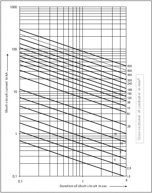
Short Circuit Current The maximum permissible short circuit current for different cables is based on the formula:
Ik = the maximum permissible short-circuit current in Ampere S = the cross section area of the conductor in mm2 t = the duration of the short-circuit in seconds
The formula is acceptable for an increase in temperature from 90°C at the start to 250°C at the end. Further information is given in IEC 60724 and IEC 60986. In the figure the permissible shortcircuit current is given in kA as a function of time (from 0.1 to 5 seconds) and as a function of the cross sectional area of the conductor
Ik •= 143 S t
TECHNICAL PRODUCT INFORMATION
Duration of short-circuit current
Reactance Calculations The reactance of cables can be calculated with the following formula:
2 • π Lf •
f = frequency in Hz L = inductance in H
TECHNICAL PRODUCT INFORMATION
Sheath Colours & Core Identification
Overview types, standards, core identification and sheath colour
Application Type
Low voltage MarineLine (+) Y(O)Z(af)p 0,6/1 kV MarineFlex Y(O)Zp & YOQp 0,6/1 kV MarineFlex YOZp 1,8/3 kV MarineLine (+) Y(O)Zp FR 0,6/1 kV MarineLine (+) Y(O)Zp X-FR 0,6/1 kV Medium voltage MarinePower Y(Z)OZmv 3,6-30 kV MarinePower Multiflex YQOQmv 6/10kV
Communication Marine(2)Com Y(O)Z(af)(2)c 250V Marine(2)Com Y(O)Z(af)(2)c X-FR 250V
Signal
MarineSignal (+) Y(O)Zs 250V Different sheath colours on request Standard Core identification Sheath
IEC 60092-350/353HD308 S2-2001 Black IEC 60092-350/353HD308 S2-2001 Black IEC 60092-350/353HD308 S2-2001 Black
IEC 60331-11/21 HD308 S2-2001 Orange IEC 60331-1/2 HD308 S2-2001 Orange IEC 60092-350/354Coloured tape + numbers Red IEC 60092-350/354Coloured tape + numbers Red
IEC 60092-350/376 Blue/White cores + numbers Grey IEC 60331-1/2 Blue/White cores + numbers Orange IEC 60092-350/-351/-376Black cores + numbers Grey
Core identification
Low voltage power cables 0,6/1 kV -1,8/3kV – According to HD308 S2-2001
Notes 1) PE = protective conductor - beschermingsleiding - Schutzleiter - conducteur de protection N = neutral conductor - nulleiding - Neutralleiter - conducteur neutre L, L1, L2, L3 = phase conductors - faseleidingen - Phasenleiter - conducteurs de phase 2) Nr. =black numbered - zwart genummerd - schwarz nummeriert - noir numéroté
Communication Cables 250 V Pairs (n x 2 x y mm2)
1 2 3… etc. 4… etc.
Triples (n x 3 x y mm2)
1 2
3 4… etc. 5… etc. 6…etc. Signal Cables 250 V Multicores
1 2… etc. Medium Voltage cables 3,6-30kV Triple Cores (YZOZmv, YQOQmv)
1 2 3


