6 minute read
Technical Bulletin 147


Clarification on manufactured, connection and telescopic chimney/flue joints Date issued: 19 April 2022
Note: This version of Technical Bulletin (TB) 147 replaces the version originally published on 15 July 2010, which is now withdrawn. This version has been reviewed and revised where appropriate to ensure that it remains both current and relevant.
This Technical Bulletin has been produced to clarify the differences between a manufactured joint, a connection joint and a telescopic joint in relation to concealed vertical and horizontal chimney/flue systems.
Introduction
This Technical Bulletin identifies the differences between manufactured, connection, and telescopic chimney/flue joints.
It is important to recognise that longitudinal seam joints along the length of chimney/flue section are considered to be a manufactured joint.
This TB also details several manufacturing techniques for the fabrication of chimney/flue lengths incorporating longitudinal seam joints.
Background
With the introduction of Building Regulations for ‘chimney/flues in voids’ and the requirement for the inspection of joints and bracketing, boiler and chimney/ flue manufacturers are continuously looking into ways to make life easier for both the appliance installer and maintenance engineer.
Note 1: For guidance on flexible concentric flue systems, see TB 139: Room-sealed, fanneddraught vertical condensing flexible flues concealed within voids(1) .
Extended concentric flue lengths
More recently, longer concentric chimney/flue sections have been developed that can be installed in vertical or horizontal voids, as long as they are supported in accordance with the manufacturer’s instructions, which, in some cases, may require only a bracket at each end.
The construction of these extended flue lengths differs between manufacturers, but in all cases the inner flue section is constructed from one full-length extrusion without any hidden joints. The difference comes in the manufacture of the outer air duct. Some are made using conventional welding or mechanical lock-forming along their length, but whichever method is used, they all comply with the required levels of air tightness demanded by the relevant standards, and can therefore be considered as continuous chimney/flue lengths. Appendix 1 and Appendix 2 show examples of manufactured longitudinal seams. These manufactured seams are not considered to be connection joints.
It may not be practicable or commercially viable, however, for manufacturers to produce the outer air duct from a single piece of material. Some products will therefore have a manufactured joint, made as part of the manufacturing process, at the end circumference of the air duct, ie, two sections of tube sleeved together with a material overlap and mechanically fixed during manufacture and which cannot be separated without intervention.
The integrity of the air duct is tested and maintained, meeting the required level of air tightness.
An example of a manufactured joint is shown in Appendix 1.
Flue integrity check
TB 143(2) sets a requirement for a flue integrity check to be carried out when the boiler is commissioned, including using a flue gas analyser where possible (ie, the boiler installation has a suitable air-inlet test-point), to check that: O2 = >=20.6%, OR CO2 = <=0.2%
Boiler manufacturers have agreed that this check should also be repeated at the time of annual service or maintenance of the appliance, and this is a requirement of the Benchmark service/interim work record, to be recorded digitally on the app, and/or the consumer’s documentation.
Note 2: For the purposes of this TB, maintenance is where gas work has been completed on the boiler and testing in accordance with Regulation 26(9) of the Gas Safe Safety (Installation and Use) Regulations(3) (GSIUR) is required.
The flue integrity check, alongside visual checks of the flue system and boiler combustion readings, will provide an additional means of checking the adequacy of the flue system and any joints (manufactured, connection, or telescopic).
Note 3: Where an air-inlet test-point has not been provided on, for example, older standard efficiency boilers and gas work has been completed, registered engineers and businesses should continue to check the safe operation of the appliance in accordance with Regulation 26(9) of GSIUR.
Note 4: For details of current gas safety legislation, building legislation and industry standards for the geographical areas covered by Gas Safe Register, see the Legislative, Normative & Informative Document List (LNIDL)(4) by logging into your Gas Safe Register online account at: www. gassaferegister.co.uk/sign-in Note 5: For general information about the process behind the development of Gas Safe Register Technical Bulletins and the expectations for all stakeholders, see TB 1000(5) by logging into your Gas Safe Register online account at: www. gassaferegister.co.uk/sign-in
Appendix 1: Manufactured and Connection Joints
A manufactured joint for both high-efficiency and older, standard-efficiency chimney/ flues should be considered a continuous length. Where only manufactured joints are present, in a concealed flue scenario, these joints do not normally need to be within 1.5m of an inspection hatch.
Please note, this does not preclude the other installation and inspection recommendations in Building Regulations Approved Document J (concealed Flues Section 1.47) and TB 008(6) .
A connection joint in the chimney/flue system, which is assembled by the installer, will normally require an inspection hatch within 1.5m of the joint.
Starting with the original installer of the boiler and/or chimney/flue system, a means should be provided for informing subsequently attending engineers that the chimney/flue system is constructed from a continuous pipe incorporating circumferential manufactured joints (where this applies).
It is suggested that this should be provided on/with any consumer work report provided for the installation, to be kept with the manufacturer’s installations and servicing instructions, and provided to the consumer.
Figures 1-7 opposite show examples of chimney/flue systems with manufactured seams and joints compared with different types of connecting joints.
Examples of chimney/flue joints
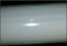
Figure 1: Laser-welded longitudinal seam
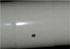
Figure 3: Example of a manufactured joint Figure 2: Mechanical lock forming longitudinal seam

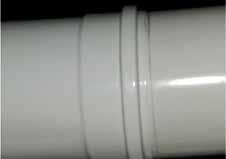
Figure 4: Example of a connection joint
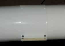
Figure 5: Extension of a connection joint
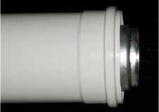
Figure 7: Extension pipe for a connection joint Figure 6: Extension pipe for a connection joint
Appendix 2: Telescopic chimney/flue joints
Telescopic chimney/flue joints, as may be the nature of the boiler manufacturer’s horizontal chimney/flue accessory, are not considered to be connection joints. Figures 8 and 9 below show a typical telescopic chimney/flue joint, before (Figure 8) and after (Figure 9) being set and mechanically secured by the installer, in line with the manufacturers’ instructions (specifying sealing tape around the telescopic metal air duct joint, in this example).
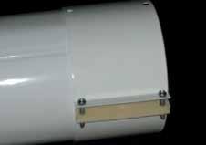

Figure 8
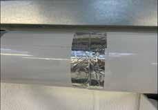
Figure 9
Bibliography
(1) TB 139 – Room Sealed, Fanned-Draught Vertical Condensing Flexible Flues Concealed Within Voids (2) TB 143 – CO and combustion ratio checks using an Electronic Combustion Gas Analyser (ECGA) when commissioning a condensing boiler incorporating air/gas ratio control valve technology. (3) The Gas Safety (Installation and Use) Regulations 1998 (4) LNIDL – Gas Safe Register Legislative, Normative & Informative Document List (5) TB 1000 – An introduction to Gas Safe Register Technical Bulletins (6) Technical Bulletin 008 (Edition 3) – Existing concealed room-sealed fanned-draught boiler chimney/flue systems in domestic premises


