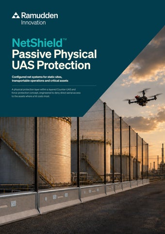
NetShield Passive Physical UAS Protection ™
Configured net systems for static sites, transportable operations and critical assets A physical protection layer within a layered Counter-UAS and force-protection concept, engineered to deny direct aerial access to the assets where a hit costs most.
NETSHIELD - PHYSICAL UAS PROTECTION NET SYSTEMS
Protect critical assets when electronic countermeasures are not enough Small UAS are used for reconnaissance, payload delivery and direct attack. Electronic countermeasures may be unavailable, restricted by spectrum coordination, or ineffective against autonomous and fibre-optically controlled systems. A physical barrier needs none of them.
Non-electronic by design. Operationally interoperable by purpose. The system is installed as a passive physical layer around selected assets. It requires no integration with radar, RF detection, EO/IR sensors, C2 software or electronic effectors; no interface, no message format, no spectrum allocation, no software baseline to maintain. It is placed inside an existing Counter-UAS architecture rather than connected to it.
T H E T H R E AT T H I S L AY E R A D D R E S S E S
Surveillance and reconnaissance
Payload delivery
Direct-approach and FPV attack
Autonomous and fibre-optic control
Overhead observation of layout, routines, equipment and personnel movement.
Objects or devices released or placed from above onto a defined area.
Single-use aircraft flown into a target, requiring a physical obstacle in the final approach.
Pre-programmed or fibreguided aircraft, with no radio link for jamming to act on.
P O S I T I O N W I T H I N A L AY E R E D C O U N T E R - U A S C O N C E P T
Detect
Identify
Intervene
Physical protection
Radar, RF, acoustic and EO/IR sensors establish that an aircraft is present.
Classification, track correlation and decision support determine intent and priority.
Electronic or kinetic effectors act, where they are permitted, available and effective.
A passive barrier stands between the aircraft and the asset when the outer layers are absent, denied or overcome.
Military and civil defence
Critical infrastructure
Events and public places
Parked vehicles, command posts and stores. Protection that goes up with the position and comes down with it.
Fuel, power and process installations, Arenas, squares, festivals and transport where a single hit means long repair hubs. Overhead cover where large times and no redundancy to fall back on. numbers of people gather in the open.
NETSHIELD - PHYSICAL UAS PROTECTION NET SYSTEMS
Selected assets, not entire facilities Physical hardening works by removing the predictable aerial approach to a defined area, not by covering a site. These are the assets where the position is fixed, the approach from above is easy to plan, and the consequence of a hit is highest.
Command posts Static for the duration of the operation
Communications nodes Antennas and cabling exposed from above
Generators and power Runs continuously, hard to relocate
Parked vehicles Concentrated, predictable, visible from above
Maintenance areas Vehicles immobilised while worked on
Entrances and checkpoints Loading zones Movement slows at a known Repeated activity at the point same place
Substations Long repair time, wide consequence
Data and control facilities Cooling and roof plant exposed
Ports and airports Open areas, scheduled movements
Fuel systems High consequence, fixed position
High-security facilities Deliveries over the perimeter
These systems are a physical protection layer. They do not detect, identify, track or defeat an aircraft, and they do not replace detection, electronic countermeasures or effectors. They are configured for stationary and temporarily stationary assets, and are not offered as protection for moving vehicles or platforms in movement, a separate product category with different requirements for weight, visibility, attachment and crew safety. No ballistic, blast or fragmentation rating is claimed or implied.
NETSHIELD - PHYSICAL UAS PROTECTION NET SYSTEMS
Three deployment profiles The profile is chosen from the operational situation, how long the asset stays in place, how quickly protection must be established, and what has to remain accessible. The net configuration is then selected within that profile. Protection for moving platforms, is a separate development area and is not offered here
Static Site Protection
Transportable Protection
Route and Access Protection
Permanent and semi-permanent overhead protection of defined high-consequence areas inside an installation, where supports can be founded and the geometry is stable.
Transportable protection for temporary groupings, configured as a kit with a defined covered area, buildup time and crew, and designed to be recovered and re-erected.
Overhead protection of the points where movement is predictable and must slow down, the places an aerial approach can be planned against.
D E F I N E D AT H A N D O V E R
D E F I N E D AT H A N D O V E R
D E F I N E D AT H A N D O V E R
Protected area, support structure, Covered area per kit, packed volume, Protected length and width, clearance span, tensioning, stand-off distance, total mass, build-up time, crew size, height, support spacing, sectioning access openings, inspection interval. tools required, re-deployment procedure. for repair, traffic and vehicle envelope.
FPV and one-way attack
Payload-carrying multirotor
Small fixed-wing UAS
Flown directly into the target. Small, fast, and steered to the last metre.
Releases or places objects from above onto a defined area.
Loiters for observation at longer range and higher endurance.
H O W T H E T H R E E C O M PA R E
Static Site
Transportable
Route and Access
Time in place
Years
Days to months
Permanent or staged
Support structure
Founded masts, or existing building structure
Free-standing masts, staked and guyed
Masts either side of the lane
Establishing protection
Project schedule, civil works included
Specified crew and build-up time per kit
Staged between traffic windows
Recovery and reuse
Not intended to be moved
Recovery and reerection
Sections removable for access
After an impact Section replaced in place
Replaced from kit spares
Lane closed, section replaced
NETSHIELD - PHYSICAL UAS PROTECTION NET SYSTEMS
Three configurable net specifications Configuration is selected from the assessed threat, the protected asset, the installation geometry and the required operational resilience. Relevant parameters include UAS mass, impact velocity and resulting energy, approach angle, payload, mesh size, system deflection, support structure and stand-off distance.
AirLite
Lightweight overhead barrier A single-layer system in Ultra High Molecular Weight Polyethylene. The strength-to-weight ratio keeps system mass and packed volume low, which is the governing constraint where protection has to be carried in, erected quickly and recovered. Profile Transportable · temporary compounds · roof openings and light support structures
AirCapture
Resilient dual-layer barrier Two complementary net materials in one assembly. The outer PPHT layer takes the initial impact; the inner PES layer remains in place if the outer layer is damaged. The finer mesh reduces the opening size available to a small airframe and to released objects. Profile Static Site · Route and Access · utilities, substations and logistics areas
AirShield
Reinforced physical protection The reinforced configuration, combining heavy-duty PPHT and PAHT netting for the highest system mass and cord dimension in the range. Selected where the consequence of a hit is greatest and where the support structure allows the corresponding loads to be carried. Profile Static Site · military installations · energy, ports, airports and high-security facilities
Construction Material Cord diameter Mesh Colour Areal weight Cord Dimensions
Single-layer UHMWPE 1.6 mm 45 × 45 mm Black 79 g/m² breaking load* 125 kgf (≈ 1.2 kN) Project-specific
Construction Dual-layer Outer layer PPHT 2.3 mm Inner layer PES 3 mm Mesh sizes 25 × 25 mm / 30 ×30 mm Colours Dark green / black Areal weight 128 + 330 g/m² Cord breaking load* 50 kgf (≈ 0.5 kN) /1.2 kN UV protection Double UV treatment Dimensions Project-specific
Construction Dual-layer Outer layer PPHT 5 mm Inner layer PAHT 6 mm Mesh sizes 45 × 45 mm / 70 ×70 mm Colours Gre, bla, wh, red, blue, sand Areal weight 355 + 450 g/m² Cord breaking load* 3.1 + 5.1 kN UV protection Double UV treatment Dimensions Project-specific
I N D I C AT I V E C O N F I G U R AT I O N G U I D E
Threat class
Typical mass
Mesh
Configuration
Deployment profile
Consumer and commercial multirotor
Under 2 kg
25–30 mm
AirCapture
All profiles
FPV and one-way attack
0.5–2 kg
25–30 mm
AirCapture · AirShield
Static Site · Route and Access
Payload-carrying multirotor
2–25 kg
45 mm
AirShield
Static Site
Small fixed-wing UAS
Up to 25 kg
45–70 mm
AirShield
Static Site
Containment, keeping UAS inside an area
Test, training
45 mm
AirLite
Transportable
NETSHIELD - PHYSICAL UAS PROTECTION NET SYSTEMS
One system. Three parts. With or without anchoring. A net, a post and a base. The net and the post stay the same whatever you build. Only the base changes, and the base is what decides where the system can go, how fast it is established and what it leaves behind.
Svea Barrier System
Base Foot
Container
Post mounted in the T-track of the Svea Barrier. Closes the ground line as well, vehicle impact, persons, debris. CEcertified and crash-tested base.
Square concrete ballast base with a centred post socket. Placed directly on grass, gravel, snow, sensitive surfaces or roof decks. No ground penetration required.
Locked into ISO corner castings and rails. No ballast at all, the container is the foundation. The kit ships inside the container it protects.
Crash-tested base, closing Anchor plate for securing Posts in three lengths, for Container frame for fitting the ground line to vehicles and the Svea Barrier to the mounting in the Svea T-track netting in one or two layers the airspace above it to UAS. ground for added stability. or the free standing Base Foot. around a container.
NetShield - Svea Barrier System
NetShield - Base Foot
Built on the Svea Barrier, with posts mounted in its T-track. It closes the ground line against vehicles and is suitable for defined areas such as enclosures or lines along façades.
Built on the square concrete ballast base. A point support rather than a continuous edge, suitable for open areas, routes and roof decks where no ground barrier is required.
Geometries Base
Geometries Base Ground line Example Scales by Also
Ground line Example Protected area Roof span
Enclosure · Line · Corridor Svea Barrier, 1.4 / 2.85 / 5.7 m modules, hinge to 100° Closed by the barrier Enclosure, external 10.2 × 5.8 m ≈ 35 m² internal Example 5.8 m
Corridor · Canopy · Screen · Enclosure Square concrete ballast base Net only Corridor, roof over a lane, repeated in bays Module repetition, not by span roof decks and surfaces where ground penetration is not permitted
NETSHIELD - PHYSICAL UAS PROTECTION NET SYSTEMS
From one asset to a whole route Five geometries are built from the same three parts. The geometry follows what has to stay accessible; the base follows where the system has to stand.
Enclosure
Line
Corridor
Roof and walls. A closed room around a defined asset.
From a façade out to a Roof over a lane. post line. Protects the Movement continues strip along a building. underneath.
Canopy
Screen
Roof only, open sides. Vertical net, no roof. Overhead denial where Lateral approach to access must stay free. a defined area.
One barrier system. Multiple roles. Svea Barrier is a modular, crash-tested system that can separate traffic, close the ground line and carry the posts for overhead UAS protection. The same barrier modules can be rapidly reconfigured as operational needs change.
Fast installation, with or without anchoring for temporary och semi-permanent set ups Rapidly deployed using a Base Foot, a freestanding Svea Barrier or an anchor plate for increased stability.
Your Safety. Delivered. STEP 01
STEP 02
STEP 03
STEP 04
Threat and site assessment
Protection design
Complete system delivery
Installation and through-life support
Four inputs: the protected asset and the consequence of a hit; the assessed UAS profile and likely approach paths; the site, support structures, spans, clearance heights and access openings; and the timeline, permanent, temporary or redeployable.
Protection envelope, net configuration, mesh and material, support structure, span, tensioning and stand-off distance.
Netting, border cords, supports, cables, tensioners, fittings, anchoring, access openings and spare sections.
Erection, documented handover, inspection routine, damage assessment, section replacement, redeployment or removal.
For technical support: info@ramudden.com | +46 63 - 10 67 73
Ramudden Global is a leading international provider of end-to-end safety solutions for critical infrastructure and traffic environments. With over 6.000 employees across 13 countries, we combine local expertise with global standards to ensure the highest quality and keep people safe every day.