by rail engineers for rail engineers
SEPT-OCT 2026 – ISSUE 222
Making the most of a major closure
PG.10
STRUCTURES AND INFRASTRUCTURE
SUSTAINABILITY AND ENVIRONMENT
SIGNALLING AND TELECOMS
PROPPING AN ARCH – BRIDGE 42 AT GROSMONT
FEELING THE HEAT
THE INVISIBLE GUARDIAN
Temporary propping has restored rail services over this deteriorating heritage bridge.
Remote monitoring can help railways manage heat-related track movement in a changing climate.
Proportional SIL allocation maintains signalling safety when migrating from relay to computer-based interlockings.
PG.18
PG.27
PG.44
www.railengineer.co.uk
Transport’s independent, confidential safety hotline. If you work in transport, your concerns about health, wellbeing and safety need to be heard. From working environment and culture, to training, welfare and equipment concerns, you can speak up safely with CIRAS. Raise a concern online, over the phone or via the app.
18 CONTENTS 06| 09| 10|
3
BEMUs for TPE
Alstom’s new battery trains promise accessible, lowemission travel, but raise questions over electrification and value.
Remembering Donald ‘Don’ Heath
Don Heath was an inspirational figure renowned for his management of the East Coast Main Line electrification project.
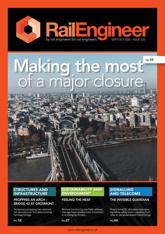
Making the most of a major closure
The recent Southeastern railway closure enabled extensive works between Charing Cross and Waterloo East stations.
PHOTO: ANDREW JEFFERY
36 27
18| 24| 27| 28| 32| 36| 40|
44
Propping an arch – Bridge 42 at Grosmont
Temporary propping has restored rail services over the deteriorating heritage bridge, allowing permanent repairs to be planned.
Crowds venture into the abyss
Greenside Tunnel’s heritage open days revived local memories and highlighted competing visions for the disused railway’s future.
Feeling the Heat
Remote monitoring technologies can help railways manage heat-related track movement, reduce disruption, and improve climate resilience.
Heat related derailments
Considering the dangers of rising temperatures and the growing potential for a series accident.
TRU - sustainability and environment update The Transpennine Route Upgrade advances carbon reduction, biodiversity, and community investment, creating lasting environmental and social benefits.
Balancing local and national requirements – CIRO’s GBR agenda
CIRO’s agenda for GBR calls for local empowerment, national coordination, better data, and whole-system thinking.
TPWS capabilities and limitations
TPWS reduces SPAD accident severity, but limitations remain in overspeed protection, junction safety, and unnecessary interventions.
44| 50| 54| 60| 66| 72|
The invisible guardians
Proportional SIL allocation helps to maintain signalling safety during migration from relay interlockings to computer-based systems.
North West rail disruption
The telecoms failure at Manchester ROC has raised urgent questions about signalling resilience and equipment protection.
Coupled thinking: the importance of professional engineers in a system of systems IMechE Chair Matt Prosser gave his annual address last month to an audience of well over 100.
Irish rolling stock
The IMechE technical tour explored Ireland’s rolling stock, maintenance expertise, and plans for future rail expansion.
Engineering rail freight growth
A recent IMechE seminar considered the challenges and opportunities faced by the rail freight business.
NDT for Heritage Railways
Improved NDT techniques are helping heritage railways to detect boiler defects and protect ageing steam locomotives.
Rail Engineer | Issue 222 | Sept-Oct 2026
4
EDITORIAL EDITORIAL
A strong strategy NEEDING A
BROADER VIEW
It is good to see the publication of Great British Railway’s (GBR) ‘Rolling Stock and Infrastructure Strategy (RSIS)’ which has much to be commended. This recognises the need for a stable longterm rolling stock investment pipeline of standardised fleets. It also commits to level boarding, moving away from diesel traction, and greater infrastructure monitoring by passenger trains. RSIS also describes how GBR’s new train fleet management function will take an integrated approach to depots and train maintenance. While these positive aspects must be recognised, the RSIS does not entirely deliver GBR’s expressed commitment to whole system engineering. For example, Battery Electric Multiple Units (BEMUs) are its principal solution for diesel unit replacement. As explained in our feature on the BEMUs procured for TransPennine Express (TPE), BEMUs have significant additional operational and capital costs. They also require very large batteries if they are to operate at higher speeds at which the power needed by a train is broadly proportional to its speed cubed. Hence, 100mph BEMUs require over twice the power of a 75mph train. Although BEMUs may be the right solution for TPE, a network-wide approach may well show that full electrification offers the increased capacity and lower whole life cost. This is most likely to be true for routes with InterCity and freight traffic. Scotland’s fleet strategy takes this approach while acknowledging that BEMUs could provide a transitional solution. The RSIS recognises that there needs to be an expansion of the electrified network while emphasising the need to improve electrification delivery. Yet it doesn’t commit to a rolling programme of electrification which is the best way of doing this. A significant omission is a strategy to resolve network capacity limitations. Although ETCS’s capacity benefits have been widely promoted, the reality is that on a mixed-traffic railway it only offers minor capacity benefits. This is because, for such routes, ETCS cannot address the far more dominant constraints of infrastructure configuration and a mix of trains with different performance and stopping patterns. While RSIS expects ETCS to reduce whole-life cost, its implementation is proving to be costly. Though RSIS acknowledges high rolling stock retrofit costs, it does not mention the cost of ETCS fitment to new trains which industry sources advise is around £0.5 million per train. Furthermore, the rebaselining of the East Coast
Rail Engineer | Issue 222 | Sept-Oct 2026
Digital Programme indicates increased expenditure since its £1.9 billion cost was announced in 2024. On routes with significant freight flows, there are large potential capacity gains from 90mph electrified intermodal freight trains. This is because, from a timetabling perspective, such trains behave like 125mph stopping passenger trains as our ‘Engineering Freight Growth’ feature explains. In this respect RSIS falls short of a whole-system approach as it is only concerned with passenger trains. Hence this capacity benefit for both passenger and electric freight trains is not considered. Yet, increasing electric freight traction could well be the most costeffective way of increasing capacity on mixed traffic routes with heavy freight flows. As Malcolm Dobell describes, the need for whole system thinking was emphasised by the new Chair of the IMechE Railway Division, Matt Prosser, in his Chair’s Address. This includes gauge-clearance and the need to fund adhesion mitigation. He also explains the complexity of battery trains which he considers to be suitable for lower-frequency, non-freight routes. He also stressed the capacity benefits of electric freight trains. Our feature on Irish rolling stock describes how Irish Rail has the capability for whole-life maintenance, including heavy overhauls, for all its trains. RSIS is considering the option of GBR owning its own trains as well as a fresh approach to train maintenance. It will be interesting to see whether GBR considers this Irish whole-life train stewardship model. However GBR is organised, within its large complex rail network it will always be difficult for those focused on one part of it to make the best whole system decisions. The Chartered Institution of Railway Operators (CIRO) proposes how this can be addressed in their
PHOTO: ALSTOM
5
THE TEAM Editor David Shirres editor@railengineer.co.uk
Production Editor Matt Atkins matt@rail-media.com
Production and design Adam O’Connor adam@rail-media.com
Engineering writers bob.hazell@railengineer.co.uk bob.wright@railengineer.co.uk clive.kessell@railengineer.co.uk david.fenner@railengineer.co.uk graeme.bickerdike@railengineer.co.uk malcolm.dobell@railengineer.co.uk
Alstom’s BEMU for TPE.
mark.phillips@railengineer.co.uk paul.darlington@railengineer.co.uk
‘Locally empowered, nationally coherent’ policy document. Although this paper concerns railway operations, much of it will be applicable throughout GBR. In respect of signalling, Kevin Chivers considers the safety integrity of staged signalling control transfers from relay interlockings to computer-based interlockings to explain how this can be ensured by a proportional SIL-Allocation Method. Assurance arrangements to ensure systems integrity are part of Paul Darlington’s feature on the potential cause of the recent communications failure at the Manchester Rail Operations Centre which caused massive disruption. The development and operation of Train Protection and Warning System (TPWS) is considered by David Fenner. He explains that, while TPWS has dramatically reduced instances of signals passed at danger, it has its limitations. Derailments caused by track distortion were also very rare until there were two on consecutive days recently. With ever hotter summers, we consider mitigation for track buckles in hot weather. As Graeme Bickerdike reports, over a thousand people recently had the chance to walk through the closed Greenside railway tunnel between Leeds and Bradford to demonstrate how this could be part of an active travel route. Putting such historic structures to good use is a great idea. The 1846-built Bridge 42 is certainly put to good
DAVID SHIRRES
use carrying the heritage North Yorkshire Moors Railway. Yet, to continue to do so its arch needed to be propped prior to a permanent repair as Bob Wright describes. Non-Destructive Testing (NDT) on heritage railways is the subject of a feature by Clive Kessell. This describes the challenges of mandatory steam boiler inspections and novel NDT techniques to reduce their cost and complexity. The complex interactions between the different work packages undertaken during the recent 22-day Hungerford Bridge blockade are considered by Mark Phillips. His feature explains how the success of this blockade was largely due to the meticulous planning which was the result of the integrated approach taken by the Southern Renewals Enterprise. We also feature the complex Transpennine Route Upgrade (TRU) programme with an update on its sustainability and environmental achievements. Our report shows how TRU has added social value, funds carbon reduction, is achieving a net gain in biodiversity and spent £405,507 on community projects. Finally, we remember Don Heath who directed delivery of the seven-year East Coast Main Line (ECML) electrification project almost exactly on time and to budget. The ECML electrification is his legacy. Yet, sadly, the legacy of later poorly-managed schemes was Government not trusting the industry to deliver cost-effective electrification. With more recent schemes delivered in a cost-effective manner, helped by initiatives to reduce electrification costs. It is to be hoped that trust in the industry’s ability to deliver can be regained.
peter.stanton@railengineer.co.uk
Advertising craig@rail-media.com
Craig Smith
Rail Engineer Rail Media House, Samson Road, Coalville Leicestershire, LE67 3FP, UK. Switchboard: 01530 816 444 Website: www.railengineer.co.uk
Rail Engineer Videos http://rail.media/REYouTube
Editorial copy to Email: news@rail-media.com
Free controlled circulation Email: subscribe@rail-media.com
The small print Rail Engineer is published by RailStaff Publications Limited and printed by PCP Ltd. © All rights reserved. No part of this magazine may be reproduced in any form without the prior written permission of the copyright owners. Part of:
RAIL ENGINEER EDITOR www.rail-media.com
Rail Engineer | Issue 222 | Sept-Oct 2026
6
NOTICES
DAVID SHIRRES
BEMUs for TPE ALL PHOTOS: ALSTOM
Secretary of State for Transport Heidi Alexander MP visited Alstom’s Litchurch Lane works in Derby on 11 September to announce contracts worth more than £1.2 billion for 29 new five-car Battery Electric Multiple Units (BEMUs) for TransPennine Express (TPE). The trains will be built at Derby and financed by Rock Rail. They will be the UK's first mainline BEMUs. A key feature is that they will offer level boarding.
These contracts are for a rolling stock order worth approximately £800 million and maintenance agreements worth around £200 million. The cost of these trains is not clear as the rolling stock order includes the provision of charging facilities at Saltburn, Scarborough, and Hull as well as depot facilities. The maintenance contract, which will support over 100 jobs, will run for an initial eight-year period with the potential for a further eight-year extension.
Alstom’s Adessias
(Above) Interior mock-up at Litchurch Lane works. (Below) Level Boarding graphic.
Rail Engineer | Issue 222 | Sept-Oct 2026
These trains will be the first deployment of Alstom’s Adessia Stream platform in the UK. Alstom advises that this is the result of a £35 million three-year development programme to adapt the Adessia platform for the UK. Alstom’s website describes the Adessia platform as “stateof-the-art high-floor multiple units”. Hence it seems likely that a significant part of this development work was designing a unit with a constant floor height close to the UK standard platform height to provide level boarding at every door. This would have involved repackaging underframe equipment such as transformers and traction equipment. As we describe elsewhere in this issue, the BEMUs that Alstom have built for Dublin’s DART+ offer level boarding and have roof-mounted battery packs. With a floor height of around 915mm and an extendable ramp, these trains will offer unassisted boarding at 85% of existing UK railway station platforms. To ensure level boarding at all TPE stations the TransPennine Route Upgrade (TRU) is adjusting platform heights at 19 stations. These five-car units will be 121-metres-long and operate at speeds of up to 110mph. They will provide around 300 seats, including those in the first class area, and will have catering facilities. Each train will also have three dedicated wheelchair spaces, two accessible toilets, family-friendly areas, and buggy storage. They will offer passengers modern amenities including Wi-Fi, air conditioning, power and USB-C charging at every seat, enhanced luggage provision, real-time passenger information systems, CCTV, dedicated cycle storage, and quieter, more comfortable interiors. TPE advises that indicative routes for these trains are between Liverpool and Scarborough, Manchester Airport
NOTICES and Saltburn, as well as between Manchester and Hull. They will displace Class 185 Diesel Multiple Units (DMUs). TPE confirms that several of these units will be retained for the Liverpool-Manchester-Sheffield-Doncaster-GrimsbyCleethorpes route.
The procurement of these trains is great news for Alstom’s Derby Litchurch Lane plant where they will be built. Alstom UK Managing Director, Rob Whyte advises that this investment will safeguard more than 350 highly skilled jobs in Derby and over 5,500 roles across the UK supply chain. Manufacture of prototype units will commence in 2028. However, series production will not start until these prototypes have been tested and validated. For this reason, it is expected that these trains will not enter service until December 2034. Though some commentators have commented on the length of time it will take to get these trains into service, this programme has clearly taken account of recent difficulties introducing new train fleets. Whyte reinforces this point by stressing that this approach avoids the rework and retrofits that have caused problems during recent UK fleet introductions. He advises that the programme is well thought out, risk based, and can be accelerated if development and infrastructure commissioning allow. He advises that another reason for this lengthy programme is that TRU infrastructure upgrades, including electrification, need to be completed for these new trains which should not be parked in fields waiting for the infrastructure to be ready for them.
01483 763 558 www
www.woking-homes.co.uk administration@woking-homes.co.uk Registered charity no. 1120447
TRU infrastructure works The TRU programme will fully electrify 112km of the route between Manchester and York. It has already electrified about 25% of this route between Manchester and Stalybridge and between York and Church Fenton. TRU’s other work includes the installation of digital signalling, additional passing loops, additional tracks, a grade separated junction at Ravensthorpe, and improvements at 23 stations. The programme aims to reduce journey times by up to 10 minutes between Manchester and Leeds and up to 14 minutes between Manchester and York, while boosting capacity by about 30% which includes 15 extra freight paths with tunnels gauge-cleared for intermodal trains. The programme has a current workforce of about 5,000 and is expected to have cost £11.5 billion by its estimated 2034 completion date.
“I’ve never found a more perfect example of how older people should be cared for than Woking Homes.” Former Chairman, Age UK, Waverley
Woking Homes is a railway charity providing residential and respite care primarily for former railway employees and their close family. Our team provide outstanding care at affordable rates in a friendly, caring and homely environment.
To find out more about permanent or respite stays, visit our website or get in touch.
Rail Engineer | Issue 222 | Sept-Oct 2026
7
8
NOTICES
Whole system engineering? The formation of Great British Railways (GBR) should enable a whole system view to be taken to derive the optimum whole life cost rolling stock / infrastructure solutions. The BEMUs ordered for TPE will run under battery power on non-electrified lines to Saltburn, Scarborough, and Hull for respectively 53, 67, and 67 km. While the use of battery traction in this way may be appropriate, Rail Engineer was interested to know how the Department for Transport (DfT) has confirmed that battery trains are the optimum solution before authorising this contract for these trains. Hence the DfT press office was asked how the choice of BEMUs rather than electrification was justified. Its response was that TPE or Network Rail should be contacted for this information. It was then pointed out that the DfT should have this information to justify the £1 billion spend on these units. However, there was no further response from the DfT despite emails and phone calls chasing this up. In the absence of a response from the DfT, Rail Engineer made an indicative assessment of the costs and benefits of this BEMU procurement and the alternative of EMUs and electrification as shown below. » Estimated maximum cost of new depot and charging infrastructure at three sites from previous contracts to be £200 million. If so, TPE BEMU vehicle cost is 600 / 145 = £4.1 million » Cost of previous EMU order which was in 2024 for 9 x 10-car Class 345 costing £220 million. With allowance for inflation, cost per EMU car = £2.6 million. » Hence TPE BEMU is £1.5 million per car more expensive than Class 345 EMU. » A large part of this additional cost will be batteries and associated traction and cooling systems. Other reasons for additional costs are level boarding, higher quality interior for long distance services, and 110 mph running. Rail Engineer’s informed guess is that 50% of extra costs are battery related with 25% for the batteries themselves. » On this basis associated battery costs are about £0.75 million per car including £0.4 million for the battery. Industry estimates a battery life of 10 years. Hence, total battery cost per car is around £2 million or £290 million for the complete fleet. » There are also additional operational costs from battery weight, say four tonnes per coach, and higher energy costs due to lower battery energy efficiency.
Rail Engineer | Issue 222 | Sept-Oct 2026
» Electrifying the lines to Saltburn, Scarborough, and Hull would require about 400 single track kilometres (stk) of electrification. If delivered by a steady rolling programme as in Scotland this would cost circa £1 billion. » This electrification would not just benefit these TPE BEMUs. Other passenger operators use these routes and there is also significant rail freight traffic to Hull and Teesside on the Saltburn branch. Operating such freight trains with electric locomotives would increase the capacity of these lines.
Is battery best? Though the above is very much a ‘back of an envelope’ calculation, it demonstrates that the ‘Battery is Best’ message promoted by the DfT does not address the above issues and is too simplistic. BEMUs are an appropriate solution in some cases, and the TPE BEMU order may be one such case. Yet the DfT’s refusal to justify this option indicates that the BEMU option has been chosen as a matter of policy rather than engineering analysis. In this respect it is interesting to compare the DfT’s approach to Scotland’s Fleet Transition Strategy. This considers that electrification is the preferred end-state for InterCity and Suburban routes with freight services. However, it considers that BEMUs are appropriate where there is no freight market or as a transitional measure. In Ireland, Rail Engineer has reported how full electrification is the preferred solution for the Cork Area Commuter Rail programme which will introduce an intensive commuter service and be Ireland’s first 25kV electrification. This is, in part, due to the electrification cost-saving measures developed by Network Rail. Scotland’s emphasis on Inter City routes acknowledges the laws of physics. Due to aerodynamic resistance, at higher speeds, these require the power needed to move a train to be proportional to the cube of its speed. Hence at 100mph and 125mph a train requires respectively 78% and 278% more power than at 75mph. This explains why BEMUs are not suitable for 125mph services and that if they operate at 100mph, as the TPE BEMUs can, their battery range is significantly reduced. Though the £1 billion contracts for these TPE BEMUs to be built at Derby is certainly good news, it would seem that a whole system approach has not been taken. This also begs the question of where, in the shadow of GBR, is the engineering focus to ensure that optimum whole system decisions are taken in respect of infrastructure and rolling stock.
OBITUARY
DAVID SHIRRES
PHOTO: RETIRED RAILWAY OFFICER'S SOCIETY
F
or railway managers of my generation, Don Heath, who died in August aged 86, was an inspirational figure renowned for
his management of the East Coast Main Line (ECML) electrification project.
His project responsibilities were much more than electrification for which the authorised budget was £174 million. It included a £132 million rolling stock procurement of 31 x Class 91, 21 x Class 90 electric locomotives, 282 x Mark 4 coaches and 4 x Class 317 EMUs, as well as complex resignalling schemes at York (£16 million) and Newcastle (£27 million). The authorised cost of electrification and rolling stock was £306.3 million at 1983 prices. The first electric train between King’s Cross and Edinburgh in 1991 marked the completion of this seven-year programme, which was just eight weeks late and over budget by 4.4%. At today’s prices the total cost of the 1,400 single track kilometres (stk) of the ECML electrification was £0.7 billion or £0.5 million per stk at 2026 prices. Don wrote a Rail Engineer article in
Remembering Donald "Don" Heath OBE 2017, titled ‘Electrification as it used to be’. This explains how the project was controlled and its innovative solutions. He acknowledged that some aspects were easier 40 years ago. For example, the much lower traffic levels enabled headspans to be installed with a four-track line blockage during the day. There was also no requirement for Environmental Statements. I had the opportunity to speak to Don after he had been asked to advise the Great Western Electrification Programme (GWEP) project. He told me that no one wanted to listen to him as the senior project team did not consider his British Rail (BR) experience to be relevant. This hubris resulted in the GWEP being delivered three years late at almost three times its original estimate after a large part of the programme had been cut back. Its electrification was delivered at £3.1 million per stk at 2026 prices. Despite much good work to reduce electrification costs since then, GWEP’s legacy is that many in Government consider electrification to be the wrong
technology and / or that the industry cannot be trusted to deliver it at an affordable price. Don’s first project management role was at BR for the Picc-Vic rail tunnel under Manchester which was ‘shovel ready’ when it was refused Government spending in the 1970s. He also project-managed West Coast Main Line improvements to allow the ill-fated Advanced Passenger Train to run at 140mph. After the ECML project, he was BR’s lead on what was then known as Crossrail. After specifying and costing the project, the Treasury considered it was unaffordable. However, Don safeguarded this work which became the basis of the project approved 15 years later by Andy Burnham, then chief secretary to the Treasury, to become the highly successful Elizabeth Line. In 2025, Don and his former colleague John Buxton published ‘Lines of Power: The Electrification of British Railways’. This book was the basis for Rail Engineer’s Railway 200 history of electrification in Issue 217 (Nov-Dec 25) which is, in part, a sad story of postponed and cancelled projects like some of those in Don’s career. Don was a railway enthusiast. Until 2010 he volunteered as a driver, guard, or signalman on the Talyllyn Railway. He was president of the Retired Railway Officers’ Society in 2008 and was also chairman of the Robert Stephenson Trust when it celebrated the bicentenary of Stephenson’s locomotive works at Newcastle in 2023. Don’s legacy is the electrified ECML. There were, and still are, lessons to be learnt about how this project was delivered.
Rail Engineer | Issue 222 | Sept-Oct 2026
9
STRUCTURES & INFRASTRUCTURE
Making the most of a major closure B
etween Sunday 26 July and Sunday 16 August, a major closure of the Southeastern railway took place to carry out a suite of works between Charing Cross and Waterloo East stations. The work, commissioned by the South Eastern Railway, was delivered by the Southern Renewals Enterprise (SRE).
MARK PHILLIPS
(Below) Panoramic aerial view of the skyline of London, showing Charing Cross station and Hungerford Bridge.
The South Eastern Railway, a relatively new authority, unites track (Network Rail) and train (Southeastern) under a single leadership team with clear accountability. Key objectives are better train and infrastructure performance, targeting investment where it is most needed. Southern Renewals Enterprise is a new partnership formed between Network Rail (Southern Region) and four specialist partners (AtkinsRéalis, Octavius, VolkerRail and VolkerFitzpatrick) to deliver the Southern Region’s renewals portfolio. The Institution of Civil Engineers' (ICE) Project 13 has been
PHOTO: ISTOCKPHOTO.COM/SHANSCHE
10
Rail Engineer | Issue 222 | Sept-Oct 2026
adopted in other UK infrastructure projects in different sectors; nuclear, health, water etc., but Southern Renewals Enterprise is the first Project 13 Enterprise in the rail sector. The project started life with the need to renew Belvedere Road Junction, located between the south end of Hungerford Bridge and Waterloo East station, and plain line renewal of one track through Waterloo East. Eventually other major works were included such as platform reconstruction at Charing Cross and various other structural works.
11
STRUCTURES & INFRASTRUCTURE Charing Cross platforms
PHOTO: ISTOCKPHOTO.COM/NIRIAN
Almost 20 years ago, the three island platforms at Charing Cross had been identified as needing renewal and updating. The opportunity was taken, in the period of much reduced passenger traffic during Covid lockdowns, to deal with those parts of the platforms under the station canopy. The remaining lengths out in the open were to be the subject of this project. Evidence of subsidence, creating a risk of slips, trips, and falls as well as corrosion to steelwork made the renewal a priority. It was also considered that there was a risk that regulating authorities might order the closure of some parts of the platforms, pending repair, which would seriously reduce the lengths of train boarding/ dismounting available to customers. The option which had all the signs of providing the most efficient way of working and was
likely to be the most economical was to go for a 22-day closure of the railway. This would enable the work to be carried out in one continuous operation, without having to reinstate the lines to rail services several times. During the evaluation of the options for possessions to carry out the switch and crossing renewal, the plan evolved to include the platform works. Such a major closure of the route would be a perfect opportunity to rebuild the
platforms. In fact, the concept of one continuous closure possibly suited the platform works even more than the track works. It would obviate the need for temporary reinstatement of platform areas, a hybrid of old, new, and temporary surfacing, on many occasions. The diseconomy of such a stop-start approach to the works is self-evident, as is the increased safety risks of ‘hybrid’ platforms with trains operating.
(Above) Charing Cross station.
Rail Engineer | Issue 222 | Sept-Oct 2026
12
STRUCTURES & INFRASTRUCTURE Line closure alternatives
(Below) Hungerford Bridge. (Inset) Platform reconstruction and completed.
Because the location of the work would have a very significant effect on passenger transport options in and out of central London, particularly the West End, and for local journeys involving Charing Cross and Waterloo East, Network Rail consulted with Transport for London (TfL). TfL had developed a modelling system which can show the predicted changes in passenger movements, taking account of all travel modes: tube, bus, National Rail, cycle, foot, taxi and private car. PHOTO: NETWORK RAIL
TfL’s system was used to model the likely effects of the 22-day closure. The results of this were pivotal in enabling South Eastern Railway to confirm the decision to proceed with the major one-off closure – a great example of synergy between transport authorities. Services that normally run to Charing Cross would be diverted to Cannon Street, Victoria, or Blackfriars, with some trains terminating at London Bridge. Further out, there would be many minor routing alterations and calling patterns with one or two services having their frequency halved, but overall, the provision of a viable service for travel in and out of London was shown to be manageable. However, before deciding to opt for the 22-day closure, two other principal options had been considered. These were to use weekend only closures or to use four nine-day closures, centred around Bank Holidays. Either of these options would have caused repeated disruption to customers and businesses spread over anything between as long as a year to 18 months. Using the preferred one-off closure meant avoiding weekend after weekend of disruption with the continual impact on the tourism and leisure economy. By using the summer dates chosen, when passenger numbers are reduced by 20% during school and commuters’ holidays, the overall cumulative disruptive effect would be lessened. Closure for 22 days also gave sufficient working time for all the multiple work items – track, platforms, bridge repairs, and drainage – to be completed. Furthermore, the complex alterations to train services necessitated by the closure only had to be put in place and explained to customers only once, which was done by a very effective and well publicised awareness campaign leading up to the closure.
PHOTO: NETWORK RAIL
Resources and facilities The Charing Cross and Waterloo East programme was delivered through the Southern Renewals Enterprise model, with VolkerRail delivering the Track and S&C renewals, and VolkerFitzpatrick delivering the reconstruction of Platforms 1-6 at Charing Cross
Rail Engineer | Issue 222 | Sept-Oct 2026
STRUCTURES & INFRASTRUCTURE duty blockade managers and the engineering supervisors. Jubilee Yard, near to Borough Market Junction, was used as a logistics centre, shared by all the contractors involved. This was the principal welfare and messing facility for staff. It was used for delivery and recovery of materials, being especially useful for stockpiling GRP modules for the platforms and pre-assembled S & C panels, in addition to many other individual items, such as loose track components. VolkerFitzpatrick was put in charge of the use and management of Jubilee Yard. It was for their own needs to fulfil their part of the works but was made equally available to the other partners.
PHOTO: NETWORK RAIL
(Above) Platform reconstruction, showing cranes either side.
duplicated, resources. It proved to be a very good working partnership and gave some overall reduction in overhead costs. A separate welfare area for staff working on the platform works was set up in the forecourt of Charing Cross station. PHOTO: NETWORK RAIL
(Left) Waterloo East footbridge repainting. (Below) Waterloo East footbridge repairs. PHOTO: NETWORK RAIL
and refurbishment works at Waterloo East. Network Rail's Works Delivery team delivered structural refurbishment works on Hungerford Bridge, while South Eastern Railway used the closure to undertake additional maintenance and passengerfocused improvements at Charing Cross and Waterloo East stations. Crucially, these were not treated as separate projects simply taking place at the same time. The teams planned the programme collectively, understanding the interfaces between each workstream and sequencing activities around the track programme and engineering train movements. This integrated approach allowed the different teams to share access, logistics, and resources, and maximise what could be delivered during the 22-day closure and reduce the need for future disruption. The possession for the whole project was of all running lines between the buffer stops at Charing Cross and the country end of Waterloo East. Occasionally, when it was available on weekend overnight periods, the possession was extended further countrywards to allow access to Jubilee Yard and the Road Rail Access Point. Two available locations played key roles in the successful progress of the works. James Forbes House, near to Metropolitan Junction, normally the depot for the London Bridge Delivery Unit, became the base throughout for the
13
This arrangement had several benefits. It was only necessary to provide one team of security staff, mess, and other facilities, rather than each contractor having to provide their own,
Rail Engineer | Issue 222 | Sept-Oct 2026
STRUCTURES & INFRASTRUCTURE
PHOTO: ISTOCKPHOTO.COM/NICKOS PHOTO: NETWORK RAIL
PHOTO: NETWORK RAIL
14
(Above) Hungerford Bridge. (Inset) Platform reconstruction and Hungerford Bridge repainted.
Throughout the closure there would be an average of around 200 staff on site at any time. It had been planned to work an eight-hour shift pattern (nine-hour in practice for overlap purposes). In view of the extreme heat, it was as well that a longer shift had not been planned. Incidentally, daily deliveries of cooled, bottled water were made regularly available to all staff during these unusual working conditions.
Rail Engineer | Issue 222 | Sept-Oct 2026
Platform works The replacement platforms are constructed from GRP units, with a supporting steelwork structure. The GRP modules forming the platform surface are of three types. These are the edge units, behind which are placed the tactile surface units and behind those the yellow ‘warning line’ units. All of these units are easily placed, butted up, resting on a framework of GRP I beams. They, in turn, sit on the new steelwork. The ‘warning line’ units and the edge units come ready coloured with yellow and white strips respectively moulded in the plastic formula, which will avoid the need for regular repainting as with the traditional markings on concrete, tarmac, or paving slab platform surfaces. The manufacturer, DURA, quotes 80-100 years life expectancy for the GRP units. Network Rail will be well pleased if a lifespan similar to that can be achieved in practice. The method devised for demolition and reconstruction of the platforms is ingenious. The location of the work, on a high viaduct, ‘landlocked’ from any easy means of access for heavy or large volumes of material, required the most practical approach. A few possible solutions were considered. While much of the new materials, particularly the GRP modules, could be loaded onto road-rail vehicles at Jubilee Yard by the use of road mobile crane, removal of the spoil from the demolished old platforms was a different matter.
15
STRUCTURES & INFRASTRUCTURE
PHOTO: NETWORK RAIL
Delivery and removal of material by engineering trains had to be ruled out because the track renewal works at Belvedere Road Junction would preclude train movements. Transporting materials using barges on the River Thames would severely disrupt road traffic on Victoria Embankment (closing all lanes) and Northumberland Avenue. Moving the material out through the station and to the forecourt/car park area would have to have been done in small quantities using trolleys and wheelbarrows. Also, it would conflict with the use of the forecourt area for the staff welfare site. So, discounting all those possibilities, the solution adopted was to position two self-erecting cranes below the viaduct and adjacent to the work, one in Villiers Place and the other in Northumberland Avenue. However, the public street areas here are very busy, with many retail
businesses, pedestrians, and road traffic. To put this plan into practice required many months of negotiations with all the interested parties which included the local authority, businesses, utility companies, TfL, and even the nearby Playhouse Theatre. Agreement was needed to close off the two streets, one on each side of the viaduct, to create two working compounds to site the cranes, provide storage areas and to allow lorry movements both to and from site.
Subscribe to our free publications at www.railsubs.com
Many detailed provisions had to be agreed, for instance, misting to reduce nuisance from dust; safety barriers and hoardings; new diversionary routes for pedestrians; and noise reduction measures. Though it should be noted that locals were warned that it would not be possible to eliminate all noise as the work would be 24/7. It is a mark of the success of the agreed arrangements that, despite there being around 70 or 80 affected businesses in the
GRP platform units.
Rail Staff Christmas Carol Service 2026
with London’s Transport Choir St Mary’s Somers Town Eversholt Street, London NW1
Thursday, 17 December, 2026
12:30 HOURS [PLEASE DRESS FOR THE SEASON]
Followed by light refreshments
Proceeds of the collection donated to charity www.rail-media.com
All are welcome to join our supporters and sponsors as the Railway Family comes together to celebrate the Christmas Season Rail Engineer | Issue 222 | Sept-Oct 2026
16
STRUCTURES & INFRASTRUCTURE
PHOTO: NETWORK RAIL
(Above) Hungerford Bridge looking southwards.
immediate vicinity, Network Rail received only eight complaints during the whole three weeks of work. Platform demolition proceeded to plan until one of the cranes started to operate much more slowly than was expected and this could not be rectified. This led to the planned removal of spoil falling 40 hours behind programme. Large quantities were accumulating at track level unable to be craned to road level. This was alleviated by deploying engineering trains being used by VolkerRail for the track works alongside and loading the spoil that way to remove it from site by train and not by lorry. This measure achieved resumption of the scheduled programme. Zen Nichols, project director for the works, told Rail Engineer that this intervention was the only significant change that had to be made throughout the whole closure.
Track works For the renewal of all the switch and crossing work at Belvedere Road Junction, comprising 16 point ends, as much as possible of the S & C and the associated plain line was made up as pre-assembled
Rail Engineer | Issue 222 | Sept-Oct 2026
panels at Hoo Junction in Kent and delivered to Jubilee Yard. The remainder was taken to site as loose components. Fibrereinforced Foamed Urethane (FFU) bearers were used throughout, and the work was carried out in five main stages. In all, 37 engineering trains were deployed for this work and for the 468-yard plain line renewal of Platform A road at Waterloo East. (There were an additional seven engineering trains for some of the other works within the closure.) In addition, some drainage work was done and three under track crossings installed. Within the track layout across Hungerford Bridge, some work was done to replace cleats which secure wheel timbers in place. This work could have been done by VolkerRail, but it was decided to leave it with the locally appointed trackwork contractor, Balfour Beatty.
Further works The closure was also used to reglaze the footbridge at Waterloo East. This was done by SET staff, with steelwork repairs and repainting, done by VolkerFitzpatrick. In addition, there is an ongoing four-year project to carry out repairs and repainting
of the whole of Hungerford Bridge. This work is now in its second year. Most of the work is being carried out in normal working hours and with trains running because the work areas are screened off. However, this closure gave opportunity for easier access to some work locations. This was all achieved without interference to either the platform works or the track works. The costs of the various works were roundly £20 million for the track works, £13 million for the Charing Cross platform reconstruction, and £5 million for the work to the footbridge at Waterloo East. There seems no doubt that this project benefitted from the efficiencies of being tackled comprehensively in one major closure using an enterprise approach. It is clear that the successful outcome was largely attributable to the meticulous and detailed planning that went into the many aspects of a complex operation. This approach may become a template to be used more often in future when the combination of works required, and the geographical situation indicates the appropriateness of a similar closure.
Synthetic S l e e pe r Simply working & sustainable
S U S TA I N A B I L I T Y
R A I LW AY T E C H N O L O G Y
State of the Art
SEKISUI CHEMICAL GROUP: Enhancing Lives, Preserving the Planet. At Sekisui, we’re dedicated to advancing the quality of life worldwide while championing the protection of our planet.
SEKISUI CHEMICAL GmbH Patrick Childs T: +44 (0) 7966 598 055 E-Mail: childs@sekisui.de www.sekisui-rail.com
18
STRUCTURES & INFRASTRUCTURE
Propping an arch
Bridge 42 at Grosmont
BOB WRIGHT
PHOTO: ANDREW JEFFERY
D
uring late 2025, accelerating deterioration of North Yorkshire Moors Railway’s (NYMR) Bridge 42 led to concerns over the structure's ability to safely support operational railway loading. In December, it made the difficult decision to temporarily close this to rail traffic.
The NYMR is a heritage railway between Pickering and Grosmont where it connects to Network Rail’s Eskdale route. Like many others in the UK, it is more than just a tourist attraction – it is a vital heritage, economic, and community asset that boosts the regional economy, protects railway heritage, and supports local livelihoods. A long-term closure to repair the structure during the main tourism season would have had adverse effects, both to the railway and to the local economy.
Rail Engineer | Issue 222 | Sept-Oct 2026
Long history The Grade II listed Bridge 42 at Grosmont has carried the railway over the River Murk Esk since 1846, when John Birkenshaw, for the York and North Midland Railway, replaced the earlier bridge that had carried the predecessor horse drawn tramway. The bridge is a single semicircular arch, spanning 18.2 metres. The arch barrel is of brickwork with sandstone radiating voussoirs, spandrels, and parapets. The bridge carries every train on the railway – around 10,000 movements each year – including those continuing to Whitby over Network Rail tracks. The railway has been aware of the structure's degeneration, but a detailed investigation by GGP Consult revealed that in the two years since the previous inspection, further deterioration had taken place. Trial holes excavated above the arch revealed significant mortar loss in the extrados and failure of the existing waterproofing, with significant water penetration through the structure. Further detailed examination revealed delamination between rings, water ingress, and historic repairs of varying quality.
19
STRUCTURES & INFRASTRUCTURE
180
540
1080
1440
180
1620
360
1260
1260
360
1620
180
1440
1080
540
13373 13500
1260
1080
1440
180
1620
360
1260
1260
360
1620
180
1440
1080
540
2360
540
3103 Centre of crown to top of foundation - 5493mm
2520
1260
1260
1260
1260
1815 1374
1045
3003
2680
10973 13373
500
2300
1500
GGP’s defect drawings formed the basis for assessing the structure’s capacity and the decision to suspend traffic. Significant structural work will be required to ensure that the bridge remains safe and fit for the future. Restoring it will be a complex and costly engineering project and will include restoring waterproofing and restoring the structural integrity of the masonry, while preserving the historic appearance of the listed structure. Carrying out these works during the spring and summer would have been undesirable due to the negative economic impacts of lost income of a long-term closure during the main tourism period. The decision was therefore made to embark on a complex two-stage project to refurbish the structure, firstly to install under-arch propping to guarantee safety and operational reliability and so allow trains to use the bridge during the summer operating season, to be followed by permanent repairs next winter. "Propping Bridge 42 was a carefully considered solution that keeps the bridge fully operational for the upcoming season,” says Phil Sash, director of civils at NYMR. "It also gives us the time needed to develop a detailed repair programme, which will be implemented over the winter months to secure the long-term safety and performance of this important structure”.
1137
2400
1211
13373
Complex solution CML Civil Engineering and structural support specialists, Mabey Hire, were engaged to design and install a support structure, at a cost of around £520,000. This was not a straightforward project, with very challenging access, and supports to be created within the sensitive environment of the riverbed without restricting or contaminating the flow. The unplanned cost of the project as a whole has been a challenge for the NYMR. As a registered charity it relies on the generosity of supporters to fund projects of this scale. The railway launched its Bridge 42 Appeal, which has so far raised around £400,000. The North York Moors National Park made a £50,000 contribution for this regionally significant project from its s106 Landscape and Ecology fund under its Restoration of Degraded Heritage Assets scheme.
8000
1217
2400 2411
2417
Works began in mid-April. To open access to the site, CML Civil Engineering created a temporary access along the rail tracks from the level crossing 100 metres to the north. This would be used by its 110-tonne crane which would lower plant and materials to river level. For personnel access, a scaffold tower was suspended from the bridge’s parapets down to the riverbank below.
Designers GGP Consult developed an unusual solution to forming a foundation in the riverbed that could be installed without risk of contamination. This was to form a timber crib on each side of the river. This met the Environment Agency’s concerns regarding contamination and restricting flow through the bridge opening, which might have accelerated flow and brought
Rail Engineer | Issue 222 | Sept-Oct 2026
20
STRUCTURES & INFRASTRUCTURE a risk of foundation scour. Fortunately, the arch’s span is wider than the local width of the river's channel, and so even with 1-in-100-year flow modelling, the restriction was minimal. On the northern side, the crib was constructed on the bank. To install the crib on the south side a temporary dam was constructed along the abutment face, creating a controlled working area. A small excavator was lowered into this for each shift to prepare the stream bed and to place materials. One thousand reclaimed untreated Ekki sleepers were used to create a multi-layer crib. Ekki is an extremely dense, strong hardwood which resists water absorption. These were bedded on a layer of SoluForm underwater concrete bagwork. These bags are designed for hand placement in watercourses, and hydrate in situ without releasing cement fines. At the end of the project the timbers will be recovered and be available for further use. Mabey Hire designed the steel supporting structure in conjunction with GGP Consult and NYMR. This comprises three pairs of MU Truss panels bearing on Superprop beams fastened to the timber cribs. Each of the trusses weighed 6.5 tonnes. These were assembled on top of the bridge and then lowered by the crane onto the beams and hauled through the arch by winches.
Rail Engineer | Issue 222 | Sept-Oct 2026
Once all three trusses were secured in place, transverse Mass 25 beams were placed across these and a network of props and bearers was installed following the profile of the arch as closely as possible. Above these, timber lagging and ply sheeting was placed against the arch intrados and props tightened to take up the load. The supporting structure steelwork bears primarily on the timber cribs but also imparts horizontal thrust into the abutment face. Once the complete propping was installed, the structure was initially visually checked every day to monitor and confirm its condition and for tightness of bearing against the structure. This has since reduced to a weekly inspection. Additional inspections will follow any flood events. Raj Sharma, contracts manager at CML Civil Engineering explained: "It was a tight programme on a difficult site: a listed arch over a river, with very little room to work. So how we worked mattered as much as what we built. Everything came in along the track by crane, and each truss had to be winched through the arch. "Careful planning with all stakeholders and our supply chain meant trains were back running over Bridge 42 on 1st June, in time for the summer season on one of the UK’s busiest heritage railways." As a result, NYMR was once again able to run trains over its full 24-mile route through the North Yorkshire Moors National Park, with LMS Stanier Black 5, No. 44806 hauling the first train from Whitby through to Pickering. Until the permanent works are complete, a single train operating restriction on this double track bridge will be in place to reduce loading affects.
22
STRUCTURES & INFRASTRUCTURE
Future work The permanent repairs to the bridge will be carried out in winter, from mid-November 2026 until early March 2027, the likely cost of this being around £350,000. The repair philosophy for the works is for minimum intervention, maximum retention of original fabric, reversible strengthening solutions where possible, and the preservation of the bridge's historic appearance. All works have been agreed with and will be monitored by Historic England. The full extent of the repairs will not be certain until the deterioration is exposed, but the worst case has been defined by GGP Consult, used in planning and designing the works, and in the Invitation to Tender to contractors. The exact scope will be identified on site by GGP and NYMR. The first phase will be works to the top of the structure. Track and ballast will be removed from the bridge and minor brickwork and lime mortar repairs carried out to the extrados. Some local stitching and pressure grouting will also be carried out to the brickwork, before the whole is waterproofed using welded DPM sheets. French drains will be installed to each side of the bridge to direct water away from the structure, which has been a contributory cause of deterioration.
Rail Engineer | Issue 222 | Sept-Oct 2026
Once these works have been completed, the propping will be removed, leaving the trusses as an access platform. Brickwork will be broken out in small areas, as far as the third ring in places, and rebuilt in traditional manner and stitched into the adjacent masonry. About 60% of the soffit has delaminated joints, indicated by drummy brickwork. In these areas stainless steel HeliBar reinforcement will be installed through the 700mm thick arch. Locations will be determined on site as Historic England wishes to restrict the number of bars inserted into the listed structure. Low pressure grouting of the whole arch with polyester grout will complete the strengthening works. The large sandstone voussoirs will be tied back into the arch barrel. Unusually, to avoid damage to the outer faces, these ties will be installed from the brickwork into the back of the voussoirs to provide invisible support. This unusual project represents one of NYMR’s most significant infrastructure challenges. The temporary propping works have successfully stabilised the structure and enabled continued railway operation, and the permanent repairs later this year will see this historic structure’s long-term future assured.
Transport Benevolent Fund CIO
All about people...
people working in public transport
Help and support for you, your live-in partner and dependent children during times of need
A comprehensive range of health, welfare and financial support for less than 20p per day.
JOIN ONLINE TODAY www.tbf.org.uk
Registered charity: England and Wales 1160901, Scotland SC047016.
24
STRUCTURES & INFRASTRUCTURE
ALL PHOTOS: FOUR BY THREE
Crowds venture
abyss
INTO THE
GRAEME BICKERDIKE
(Above) The event offered a unique experience for the community.
(Below) Locals queued along the length of the tunnel’s approach cutting. More than 1,300 people turned up to explore over two afternoons.
S
eptember was a month in which heritage was celebrated, with two weekends of open days at sites across the length and breadth of Britain. Those whose interests include railway structures were catered for in West Yorkshire – or rather under it – thanks to the efforts of a community group and National Highways, custodians of the Department for Transport’s Historical Railways Estate, which opened the gates on the disused Greenside Tunnel, extending for 618 yards between Leeds and Bradford. The organisers could not reasonably have foreseen locals’ response to social media posts advertising the event. At its peak, the queue extended out of the muddy approach cutting, under an attractive skewed bridge and onto one of the country’s highest railway embankments (also disused). Over four hours across two afternoons, more than 1,300 people – accompanied by numerous dogs – were guided through the passageway by volunteers steeped in its features and history.
Rail Engineer | Issue 222 | Sept-Oct 2026
Victorian enterprise In 1882, the Great Northern Railway (GN) entered into an agreement with the Lancashire & Yorkshire Railway to build a collection of short connecting lines which, together with a mutual assignment of running powers, allowed the companies to offer improved services. Among these schemes was the relaying of the Pudsey Greenside branch to provide two tracks and an extension westward to meet the Tingley-Laisterdyke route. It became known as the Pudsey Loop.
STRUCTURES & INFRASTRUCTURE Responsible for the line’s engineering was William Myers-Beswick who, by this time, was the only surviving partner of John Fraser & Sons, long-time collaborators with the GN. Awarded the construction contract was Charles Barker & Sons. Navvies arrived in Pudsey in January 1890, ahead of the first sod being cut on the fifteenth of the month. The ceremony took place at Westroyd Hill, the site of Greenside Tunnel’s western construction shaft which was subsequently retained for ventilation purposes. A second, temporary shaft was sunk 200 yards further east on land acquired from the owners of Pudsey Brickworks. By springtime, a workforce of around 200 was employed on site. At the tunnel’s west end, a Jubilee steam navvy – which could do the work of 20 or 30 men – assisted with excavation of the cutting, while progress was made around-the-clock with the heading, following an S-shaped alignment. On 16 January 1892, after two years of effort in unimaginable conditions, the job was done.
9 March 1892, an 18-year-old engaged in shunting operations at the east end of the tunnel was crushed between the buffers of two wagons. He survived for just 20 minutes. Scandal attended on the night of 3 January 1892 when Fred Smith – known on the works as ‘the gallant tunnel man’ – eloped with Mrs Jackson. The local newspaper reported that “Not the slightest trace has been discovered as to the direction in which they have gone.” Mr Jackson was said to be “disconsolate”.
and eventually found this [the tunnel] and I can remember coming through here when I was maybe about seven, with my sister, as a big dare. Going through Greenside Tunnel was like the rite of passage to every youngster in Pudsey.” Andy was among a group of locals who came together in 2017 to promote the idea of developing a 3.5-mile active travel route between Tyersal and the Bradford-Leeds Cycle Superhighway – through the middle of town, via the tunnel. “It’s our special landmark,” he
(Below) As stragglers leave, another group ventures into the darkness.
Catalogue of mishaps Accidents occurred with sickening regularity – a function of the risks involved and difficulties mitigating them. A jury at Bradford County Court awarded miner James Reaver £200 in damages for injuries sustained on 15 June 1891 when he thrust a steel rod into a hole within which a charge had errantly been left. A sudden explosion followed, causing one of his arms to be shattered, as well as severe injuries to his head and other arm. The contractor admitted liability. In August 1891, a navvy was descending a ladder into the tunnel when his foot slipped, resulting in a fall of about 30 feet and serious injuries being sustained, including a broken back. He was removed to his lodgings at Hill Top where Dr Hunter attended to him. And on
Light at the end? Major Yorke inspected the new railway for the Board of Trade on 24 October 1893 and trains started running a few days later. Formal closure of the Pudsey Loop came on 6 July 1964 as the retrenchment of Britain’s railway network gathered pace, having retained its operational status for barely 70 years. The tunnel has tolerated enforced redundancy ever since, except as a venue for exploits of an unofficial nature. Andy Wilson’s family moved to Pudsey in 1968 and he recalls discovering the line’s abandoned infrastructure at the end of his road: “I remember thinking ‘this is incredible’; what a flipping waste. And as years went by, we ended up strolling further
asserts and points to a collection of “forward-thinking” councils who’ve invested money in repurposing disused railway structures and trackbeds for social, health and connectivity benefits. “How would you like somewhere safe for your kids to ride?” is the question he poses to Pudsey’s parents, seeking their support. “What a wasted asset this is.”
(Above) The grand portal prompted much admiration at the quality of the masonry.
Rail Engineer | Issue 222 | Sept-Oct 2026
25
26
STRUCTURES & INFRASTRUCTURE For the masses? But others have their eyes on the tunnel too. Leeds is a thriving regional centre and the largest city in western Europe not to have trams or light rail. Back in 1993, royal assent was granted for a Supertram system, but Chancellor Alastair Darling pulled the plug 11 years later when projected costs hit £487 million. A trolleybus proposal then emerged; that collapsed too. Following the abandonment of HS2’s eastern leg, West Yorkshire Combined Authority was awarded the consolation prize of funding to examine prospects for a mass transit system. With a price-tag estimated at £2 billion, it also looks prone to the vagaries of political decision-making and timescales are now uncertain. What’s beyond doubt, however, is that one line on the map of options incorporates Greenside Tunnel. Mayor Tracy Brabin has big mass transit aspirations, with the eventual aim to reach the whole of West Yorkshire. Phase One would head south from central Leeds to the White Rose commercial and retail area, as well as pushing west to Bradford. The latter has three alignment possibilities through two corridors converging at Pudsey, with B2 and B3 largely following the old railway, heading underground through the tunnel. All of which means that the greenway proposal is now paused, prompting campaigners to seek assurances from both WYCA and Whitehall that its full proposed course will be “protected from development until a final route decision is made.” And so it should be. The Strategic Outline Case – an early stage in the government’s business case process – is due to be submitted later this year.
(Above) A group stops to peer up the capped ventilation shaft. Dripping nostalgia Gary Lemal is pragmatic. As current chair of the Greenside Greenway group, he accepts that “it’s above our pay grade. If it’s going to happen, it’s going to happen and we’d like to work with them to incorporate the cycle route.” Bikes and trams can safely share the same space, as they do elsewhere. In the meantime, “England’s largest festival of history and culture” – so claims the Heritage Open Days website – offered a chance to repurpose the tunnel, if only for one weekend. Gary applauded the Historical Railways Estate team within National Highways who were “brilliant and supportive all the way”. And so on the afternoons of 12 – 13 September, a hi-vis-clad team guided a hugely varied demographic through the darkness to the other end, looking out into the eastern approach cutting where – thanks to an act of planning blindness – a partial infilling scheme was approved in 2017 on the back of an adjacent housing development. Vehicular access to the portal for maintenance purposes is now impractical. Mary served as our escort for the 25-minute tour, pointing out the refuges to which platelayers used to scuttle when a train approached, in an era predating health and safety. We looked up the shaft to the concrete beams which cap it and enjoyed a shower where water from the hidden construction shaft penetrates the lining. The quality of stonework in the sidewalls – each block crafted by a mason’s hand – was a frequent subject of admiration, as was the courage of the navvies who drove the tunnel without any of the mechanical and technological advantages bestowed on 21st century engineers. For many, it was a revelation and painted smiles on faces. Today’s youngsters – prevented from enjoying the kind of childhood adventures that helped to shape Andy – embraced an opportunity they’re unlikely to have again. “The rumour, the noise, the history of the tunnel. So many kids went through and these kids are now in their 40s, 50s, 60s, 70s and beyond”, Gary reflects. “This is the experience dad had; this is where mum left a bottle of cider. These are the things people want to pass on; this is a bit of everybody’s history.”
Just beyond the shaft, a guide points out a feature of the brick arch.
Rail Engineer | Issue 222 | Sept-Oct 2026
SUSTAINABILITY & ENVIRONMENT
FEELING THE HEAT
R
ecord-breaking spells of hot weather across Europe had a significant impact on rail infrastructure this summer, highlighting the importance of climate adaptation measures. While the high-profile derailments at Lewes, West Sussex, and Wickford, Essex made the biggest headlines, they were part of a bigger problem characterised by cancellations, delays, and discomfort to passengers.
There is no easy solution to these problems, and the most common short-term mitigation is to send inspectors to look for signs of distress, or more often to impose critical rail temperature speed restrictions or even temporary closures. The development of a growing range of remote monitoring technologies offers further options that can reduce the risk of derailments or the need for costly restrictions on train operators. Engineers and product developers at remote monitoring specialist Senceive (part of Eddyfi Technologies) are acutely aware of the impact of climate conditions on the railway network. Having worked closely with Network Rail and other asset owners for more than 20 years, the team that developed InfraGuard, the UK’s most widely used landslip detection system, is busy on new challenges. Some of these technologies can help keep trains moving when the mercury rises to uncomfortable levels.
Hot weather impact on the track Even short periods of high temperatures can heat steel rails close to their critical rail temperature, potentially resulting in vertical or lateral movement. Research has shown that rail temperature can be 20 degrees higher than ambient. The Senceive temperature sensor provides continuous measurement of the actual rail temperature. Used as part of a wireless monitoring system, the associated wireless node sends near realtime updates and automated alerts to remote stakeholders via the cellular network or satellite comms. Where permanent way engineers are concerned about lateral rail movement (buckle) they can use other wireless sensors such the Optical Displacement Sensor (ODS). This combines a laser for precise measurement of displacement between two surfaces, a tilt sensor, and similar wireless connectivity to the temperature sensor. It can be deployed in various ways, but a common scenario is to mount the ODS on a structure such as a gantry and direct the laser at the rail web. Lateral movement is reported to sub-millimetre accuracy. Deploying a number of sensors along a critical length of track such as a high-speed curve provides continuous monitoring data and immediate alerts if pre-set thresholds are breached.
Deeper ground movement Prolonged hot dry weather can also cause deeper problems below the trackbed associated with uneven ground movement, particularly in the reactive highly plastic clays found across southern England. These soils are prone to severe volume changes leading to desiccation (shrinkage and volume loss) causing differential subgrade settlement. This can contribute to track geometry problems such as crosslevel anomalies, twist faults, and track settlement.
Remote monitoring Most of these problems can be monitored using tilt sensors such as the Senceive Nano Macro which has a High G variant for extended use in high vibration track conditions. In most applications sensors are fixed to sleepers and assumptions made about the relationship between sleeper and rail displacement. This approach has been proven for parameters such as crosslevel and twist but is problematic for monitoring settlement without well-established control points. The recently developed Senceive rail-mounted tilt meter provides a means of monitoring movement of the rail rather than the sleeper and has been tested on heavy freight railroads in the USA. Findings of independent research have demonstrated great improvement in the accuracy of vertical movement monitoring. We may have seen the back of the European heatwaves this year, but we know they will return, and practical, cost-effective monitoring solutions look set to be part of any package of measures to manage risk.
Rail Engineer | Issue 222 | Sept-Oct 2026
27
28
SUSTAINABILITY & ENVIRONMENT
PHOTO: RAIB
DAVID SHIRRES
HEAT RELATED DERAILMENTS (Above) Derailment at Lewes on 13 August.
O
ver the past 10 years there have been around 23 passenger train derailments, of which five resulted in injuries and two in fatalities. These have been the result of a wide range of causes with five derailments, 22% of the total, being due to track defects. Of these five, three were slow speed derailments on wide gauge track, and two were due to kinks in the track. These last two derailments occurred on two consecutive days this year – 13 and 14 August.
UK PASSENGER TRAIN DERAILMENTS - 2015 to 2026 Speed - mph injuries 14-Aug-26 Wickford 77 Track kink 0 13-Aug-26 Lewes 65 Track geometry irregularity 30 19-Jun-26 Elstow 49 Signal Passed at Danger 162 3-Nov-25 Shap 83 Landslip 4 26-Jun-25 Denbigh Hall Jnc 15 Signaller error 0 3-Feb-25 Roundham Heath 83 Train struck trees 0 22-Mar-24 Grange-over-Sands 56 Void under embankment 0 4-Mar-24 Walton-onThames 85 Train struck reundant rail 0 26-Nov-21 Balderton 46 Train struck tree 0 31-Oct-21 Salisbury 52 Low adhesion 14 10-Apr-21 Dalwhinnie 33 Wrong side signalling failure 0 22-Oct-20 Bognor Regis 5 Signaller error 0 12-Aug-20 Carmont 73 Train hit debris from drain 6 28-Jan-19 Penryn 16 Signaller error 0 22-Jan-18 Loch Eilt 40 Train hit landslip 0 6-Nov-17 Wimbledon 19 Wide track gauge 0 20-Aug-17 Paddington 10 Wide track gauge 0 15-Aug-17 Waterloo 13 Wrong side signalling failure 0 5-Nov-16 Southampton Docks 10 Wide track gauge 0 16-Sep-16 Watford 66 Train hit landslip 0 16-Jun-16 Paddington 8 Signal Passed at Danger 0 7-Nov-15 Knaresbough 18 Signaller error 0 26-Jul-15 Godmerham 69 Train hit cows 0
Rail Engineer | Issue 222 | Sept-Oct 2026
fatalities 0 0 1 0 0 0 0 0 0 0 0 0 3 0 0 0 0 0 0 0 0 0 0
As described in our rail safety feature in Issue 221 (Jul-Aug 2026), there has been a significant reduction in passenger fatalities, though the risk of certain types of accidents has increased. Though passengers came to no harm in most of these derailments, with an average of just over two a year, there is the potential for a serious accident.
Lewes At around 15:54 on 13 August 2026, a train formed of two four-car Class 387 electric multiple units (EMUs) became derailed 1.6km north of Lewes station. It was the rear three vehicles that derailed and subsequently overturned, coming to rest on their sides. There were around 150 people on the train when it derailed of whom 20 people required hospital treatment, some for serious injuries. There were no fatalities. Significant damage was also caused to the train and to railway infrastructure.
SUSTAINABILITY & ENVIRONMENT Preliminary analysis of OTDR data obtained from the front vehicle shows that the train was travelling at around 65mph (105km/h) as it approached the point of derailment. Preliminary OTDR data analysis also shows that the driver applied the train’s brakes as it passed the point of derailment, and that the train had started to decelerate. Rail Accident Investigation Board (RAIB) inspectors observed marks on the rails indicating that the wheels of the derailed rear vehicles had climbed over the rails. CCTV images from the derailed train and another previous train showed that, prior to the accident, there was a track geometry irregularity before the point of derailment. Indications of previous nearby track maintenance activity adjacent to this irregularity were also noted. In addition, RAIB had received several reports of rough riding at the location of the derailment from passengers on other trains.
undergo movement as moisture levels change. Although RAIB inspectors saw no evidence of a significant embankment slip before the derailment, there was also evidence of some previous movement. The above information is included in RAIB’s initial report on the accident which was published on 19 August.
Wickford At around 14:08 on 14 August, a passenger train formed of two five-car Class 720 electric multiple units travelling at 124km/h became derailed 3.4km south-east of Wickford station. The rear vehicle was the only one that derailed. Its wheels then ran on the sleepers and ballast for around 2.4km. The train remained upright throughout and there were no reported injuries to the 62 people estimated to be on board. The driver reported seeing a kink in the track which rocked the driving cab. This was confirmed by the train’s
from flying ballast. There was significant damage caused to the track, signalling, and overhead electrification equipment. The above information was in RAIB’s initial report on the accident which was published on 19 August.
Increasingly hot summers Until July this year, derailments resulting from kinks or buckles were extremely rare. Indeed, as far as Rail Engineer can ascertain, the last such derailment that caused passenger injuries was at
(Below) Rear vehicle derailed at Wickford on 14 August.
PHOTO: RAIB PHOTO: RAIB
The weather on the day of the accident was hot and sunny, with little wind. The ambient air temperature at the time of the derailment was recorded as being around 27°C by the nearest weather station to the accident. The accident took place during a sustained period of hot and dry weather. The railway embankment at this location consists of clay and sits on deposits of loose clay, silt, sand, and gravel. Both these layers are sensitive to variations in water content and may
forward-facing CCTV which shows track misalignment at the point of derailment. The train driver was reporting this track defect when an emergency call from another train passing in the opposite direction was received after that train’s driver had seen ballast flying from underneath the derailed train. The driver of the derailed train then applied the train’s brakes. The derailed train sustained damage and the other train received minor damage
Motherwell in June 1986. In this case the buckle occurred between two sets of points which had been laid in cold weather and not restressed. Forty years later, the next two such derailments occurred on consecutive days in August. It is difficult to accept that two such incidents in two days can be a coincidence especially as the common factor is hot days after a sustained period of hot and dry weather. Up to 2024, the four hottest summers on record were separated by just 0.05°C, then 2025 beat the previous record by 0.34°C and 2026 has beaten that by another 0.40°C. Hence, after years with tiny increases in record temperatures, in just two summers the record has been raised by 0.74°C. A further indication is that this year saw temperatures of 30°C or more on 40 days. The previous record was 34 days, set in 1995.
(Left) Track irregularity shown in a train’s rearfacing CCTV two hours before the derailment.
Rail Engineer | Issue 222 | Sept-Oct 2026
29
SUSTAINABILITY & ENVIRONMENT (Right) Fishplate rail joint.
In 2022, the Seasonal Challenge Steering Group published the ‘GB Rail Industry Approach to Hot Weather Management’. Its foreword notes that the very hot summer of 2022 was the first time that UK temperatures over 40°C were recorded. Yet the Met Office advise that this year’s summer has been the hottest on record by a significant amount. Network Rail’s 2024 Climate Change Adaption Plan (CCAP) notes that the impact of cold movement. In some cases, such and snow-related railway Extreme track temperatures as switches and crossings (S&C) impacts is reducing, while Where jointed track is used, and bridges, CWR is laid on flooding, heat, and subsidence 60ft (18.3m) lengths of rails are wooden sleepers. impacts are increasing. For joined by fishplates where, at A critical aspect of the example, in 2022/23 heat moderate temperatures, there management of CWR is accounted for 646,000 delay were gaps of 5mm to allow ensuring that it is stress minutes and there was a further for thermal expansion of the free at 27°C which is the 498,000 delay minutes from rails. This results in joint impact currently specified stresssummer embankment shrinkage loads and a heavy maintenance free temperature (SFT). This followed by autumn rainfall. In workload with the inspection balances the compressive force comparison, in 2023/24 storms and maintenance of 176 09F - Heat derailments - 01.docx in the rail at high temperatures accounted fishplates per mile. 2265 words for 1.3 million delay as it tries to expand with minutes. From the mid-1960s, jointed OfThe the CCAP £2.8 billion in CP7, 78% is for the tensile force at low alsoallocated containsfor Climate resilience track wasprojects progressively drainage and earthworks and only 2% is on track. It will be interesting whether, as a Network Rail’s Integrated replaced on most lines with the result of the required hot weather mitigations, including RAIB recommendations, temperatures. This respectively there will Change be a significant expenditure Welded in CP8. Rail (CWR). controls the risk of track Climate Risk increase in trackContinuous buckling and rail breaks during Assessment (ICCRA). This Unlike jointed track, CWR does considers five categories of risk not allow rails to expand as they high and low temperatures. When rails are laid below the as shown in the table below. are firmly fixed to the tracked. SFT, they are put in tension by Risk category Covers Risk pulling them by the required percentage amount before being welded Climatological – Droughts, heatwaves, wildfires 0.8 and fixed in place. This amount prolonged weather events Environmental – Vegetation growth, tree and depends on the length of 5.0 vegetation leaf fall rail and difference between Geophysical – ground Coastal erosion, scour, high / 15.5 impacts low soil moisture ambient temperature and SFT. Hydrological – water Sea level rise, storm surges, As an example, a 300-metre 12.3 impact flooding length rail laid at 11°C would Meteorological – day to Combination events 0.2 day weather Other e.g. snow, ice, fog 18.8 need to be stretched by 66.4 Rainfall 18 55mm. Temperature 29.4 Regions are also required to have a critical rail temperature As temperature presents such This is generally done by track (CRT) register for each CWR a high risk, one of the CCAP’s fastenings onto heavy concrete track section. For CWR track actions was independent sleepers which are fixed in a in perfect condition, the CRT extreme heat reviews into thick layer of ballast with ballast is generally 56°C. The CRT engineering, operations, shoulders preventing lateral weather forecasting, and customer experience to improve understanding of extreme heat risks. The engineering review was led by Sir Douglas Oakervee and considered the impact of heat on track, overhead line equipment, and distribution infrastructure affecting S&T systems. PHOTO: LES CHATFIELD
30
(Right) Stressing equipment.
Rail Engineer | Issue 222 | Sept-Oct 2026
SUSTAINABILITY & ENVIRONMENT
The Oakervee report
PHOTO: NETWORK RAIL
The Extreme Heat Taskforce report led by Sir Douglas Oakervee was published in 2023. In respect of track, it found that 23 buckles were reported in 2022 of which 13 had occurred on two consecutive days of extreme heat. Of these incidents, 18 were sites that were not on the CRT register and 15 were at, or within 100 metres, of S&C.
The report noted that heat alone is not the only factor that causes buckles, and listed a range of factors that need to be considered together with the primary deficiencies that caused the 23 reported buckles. These factors included: » Ballast condition, consolidation and profiles. » Drainage. » Sleeper condition. » Track clips and pads. » Transition zones on run off from fixed assets e.g. bridges and level crossings. » Wooden S&C bearers, shallow depth switches with shortage of ballast. » Low SFT
and in the weeks and months preceding it In effect, RAIB will be assessing the effectiveness of the mitigation measures specified in the ICCRA and Oakervee reports. Speaking at a press briefing on 19 August, Rail Minister Lord Hendy noted that it is quite clear that there is significant climate change. He advised that Network Rail's expenditure on climate resilience for earthworks and drainage in Control Period
The report made 25 recommendations which concerns improving record keeping, ensuring that lessons are learnt from the 23 buckle incidents, a programme to remove risk at low CRT sites, detailed inspections of S&C with line speed above 60 mph, reviewing competencies of all personnel concerned, consistency of national and hot weather preparedness strategies, and delivering a policy of zero unmitigated track buckles. It also suggested that there may be a case for increasing SFT to 30°C if there is sufficient mitigation for the risk of broken rails at low temperatures.
Hot weather mitigation Although the principles of CWR temperature management have been known since the mid 1960s, with ever hotter summers the risk of heat-related derailments has increased. As the CCAP and Oakervee reports show, this has been recognised for some time. As a result, additional mitigation for extreme heat has been specified. Within hours of the Wickford derailment, Secretary of State for Transport Heidi Alexander spoke to senior officials at Network Rail and the Office of Rail and Road (ORR) to ask if any blanket action need be taken following the derailments at Lewes and Wickford. It seems likely that she was assured that no such action was necessary as a result of these extreme heat mitigations. RAIB’s investigations into the Lewes and Wickford derailments will consider: (i) the effectiveness of any mitigation measures to address the risk of operating trains in hot weather; (ii) the status of the track at this location and how it was maintained; (iii) the actions of those involved and the factors that may have influenced them; (iv) the condition of the embankment at Lewes; and (v) and how it was inspected and maintained as well as weather conditions in the area on the day of the accident,
PHOTO: NETWORK RAIL
needs to be reduced to take account of anything that might reduce fixity of the rails, for example: wooden sleepers, poor ballast shoulders, and adjacent construction work. It should be noted that on hot days, rail temperatures can be 20°C above the ambient air temperature.
7 (CP7) from 2024-2029 was five times that of CP6. He had no doubt that CP8 will have increased spending for extreme weather mitigation. Lord Hendy also noted that the industry must wait for the RAIB report which will determine causes of the Lewes and Wickford derailments and make appropriate recommendations. Of the £2.8 billion allocated for Climate resilience projects in CP7, 78% is for drainage and earthworks and only 2% is on track. It will be interesting whether, as a result of the required hot weather mitigations, including RAIB recommendations, there will be a significant increase in track expenditure in CP8.
(Above) Buckled rail.
A more comprehensive report on the impact of hot weather on plain line track is given in Issue 199 (Nov-Dec 2022).
Rail Engineer | Issue 222 | Sept-Oct 2026
31
32
SUSTAINABILITY & ENVIRONMENT
TRU
TRANSPENNINE ROUTE UPGRADE
sustainability and environment update
PAUL DARLINGTON
R
ail Engineer has featured the Transpennine Route Upgrade (TRU) a number of times and two years ago reported on the programme’s sustainability strategy. This issue, with a focus on rail sustainability and environmental impact, provides an update on what has been achieved so far and is planned by the programme to further improve the lives of those living on the route. TRU is a multi-billion-pound, transformative programme to improve connectivity for both passenger and freight services between Manchester and York, and to support economic growth. The programme is impressive and will provide a greener, more reliable, faster electric railway with a reduced carbon footprint and improved air quality. The programme is also committed to providing other benefits to society, detailed in its sustainable development strategy – ‘Our Guiding Compass’ – which aims to improve sustainability and the environment along the The numbers are very impressive, but the route. A large rail programme like TRU can programme also recognises that it can be easy impact neighbourhoods and communities during to focus just on hitting the numbers and that construction, but the programme’s objective is it is important to look at the outcomes. The to also contribute positively to local businesses, programme has undertaken socio-economic communities, the local environment, and to 09F a– net TRU Sustainability and environment update – 01 to direct its approach to impact assessments leave positive impact. address this. Apprenticeships, for example, Table 1 details the programme’s social value 1889 words must deliver the right experience and skills for targets, showing progress achieved when Rail the apprentices to deliver rail programmes such Engineer first met with TRU two years ago as TRU and other work in the future. alongside an updated position for 2026.
Final target 2035
Table 1 – Progress with social value targets.
Apprenticeships Inclusive education students Young person work experience days Adult work experience days Volunteering hours Local spend SME spend
590 100,000 25,000
Achieved September 2024 280 52,489 14,557
Achieved September 2026 480 75,837 19,645
5,000 25,000 25% 33%
4,163 14,250 66.1% 34.75%
5,384 25,618 68% 36%
Rail Engineer | Issue 222 | Sept-Oct Table 1 2026 – Progress with social value targets.
SUSTAINABILITY & ENVIRONMENT help to provide real, long-term, sustainability benefits in the areas the programme is operating in. Projects typically consist of enhancing indoor or outdoor community spaces, creating opportunities for skills, education, and employment, and to support disadvantaged, under-represented or marginalised groups. In the 2026/2027 funding there will also be a greater focus on supporting projects that are creating opportunities. Some of the projects funded and completed to date include the following.
Ninety-three percent of the apprentices live within 40 miles of the TRU route and this programme will leave a lasting legacy, amounting to over £26 million in value to society, according to the Rail Social Value Tool. The apprentices are working in various disciplines across TRU, including civil engineering, project management, quantity surveying, and ecology. Many TRU apprentices also have formal education built into their apprenticeships, taking one or two days a week off work to study.
Carbon reduction TRU has a carbon reduction fund of £30 million for projects to draw on if they have a carbon reduction initiative, which may cost more than a traditional higher carbon solution. Engineers and managers in the programme have been trained on carbon reduction techniques and are now able to apply to the fund to finance carbon reduction elements of their works. Low carbon concrete is one example, which is being trialled in low-risk locations and, if successful, could be used elsewhere on the network. The programme has also now electrified 25% of the route (Manchester Victoria to Stalybridge and York to Colton Junction). This allows hybrid rolling stock to operate along the route and deliver carbon reduction in advance of the complete scheme and new electric traction rolling stock.
Manchester » Cede Foundation, conversion of a former church into welcoming community hubs. » Key Changes, improvements to a portable recording studio, supporting mental health patients at North Manchester General Hospital. » Family Unit Trust, refurbishment of an unused unit into a Family Support & Wellbeing Hub for families affected by cancer & illness.
Community fund
Family Unit Trust, Manchester.
TRU has a Community Fund, giving local community groups, schools, and charities the opportunity to apply for funding to improve and encourage the use of local spaces and services along the route in areas of high social need. A key element of the fund is that it is for local communities to decide what they need, rather than the TRU programme or central government deciding what to provide. The funding for 2024/2025 was a total of £155,000. For 2025/2026 it was £250,000, and this is being further increased to a total of £270,000 for 2026/2027. Community projects close to the TRU route are eligible to receive the funding to
» Local Food First CIC (Community Interest Company): transformation of a disused building into a Community Food Hub with a teaching kitchen. » Bee Together Community Centre & Garden: Expansion of a community food growing programme, including installation of new planting beds and pollinator flowers. » Pennine Mencap: a community garden project teaching gardening and cooking skills to adults with disabilities and autism.
Oldham
Rail Engineer | Issue 222 | Sept-Oct 2026
33
34
SUSTAINABILITY & ENVIRONMENT The fund is being independently managed on behalf of TRU by Neighbourly Ltd, a limited company specialising in administering grant funds, to ensure impartiality and good value for money. It will oversee the management and distribution of the fund, with a governance approach independent from TRU, who will only be involved to support strategic alignment. TRU still acts as the client and a scorecard has been created for projects to be assessed using the core objectives of TRU’s ‘Our Guiding Compass’, to ensure the fund is used in a way that aligns to TRU, as well as benefiting the railway and community, and for projects considered to be good value for public money.
Biodiversity net gain
Bradford » Making Sedbergh Sustainable: an upgraded community space at Sedbergh Youth & Community Centre. » A Place to Connect, Share and Thrive: a fully equipped community kitchen serving people experiencing homelessness & hardship in West Bowling. » Northcliffe Environmental Enterprises Team: an accessible outdoor space for therapeutic gardening and wellbeing.
Leeds » Junior Sports Hub: New toilets and an improved outdoor green space. » Friends of Farsley Rehoboth Burial Ground: Accessibility, rewilding and sustainability improvements. » United Hebrew Congregation: Development of a sensory garden and raised growing bed.
York » Make Space York: multifunctional climbing and seating structures in Rowntree Park, as part of an initiative to make York’s parks more inclusive for teenage girls. » Haxby Ethel Ward Sports Courts: Refurbishment of the playing fields into a multi-purpose community sports facility. » Huntington Library, development of an accessible, sensory community garden. Altogether, a total of 63 projects has so far been funded with a total value of £405,507, and TRU was awarded 'Highly Commended' at the Spotlight Rail Awards 2026 for the Community Fund initiative. The third round of the Community Fund opened for applications at the end of September. Organisations were able to apply for £5,000, with the option to request up to £10,000 where this would help deliver greater benefit. Any group or organisation with a clear social purpose and located within 5km of the TRU or within 5km of the Shipley Traincare Centre, was eligible to apply for the funding, including registered charities and CICs; community groups, community centres, and local organisations; schools, not-for-profit nurseries, and family centres; and universities, provided they are linked to a registered charitable organisation or community group with a clear social purpose.
Rail Engineer | Issue 222 | Sept-Oct 2026
TRU has committed to achieving a 10% Biodiversity Net Gain (BNG) across the programme. BNG aims to ensure that habitats for wildlife are left in a measurably better condition than they were before development began. As part of its BNG commitment, TRU has recently invested in long-term habitat enhancement works near to the route at Barnbow Wood and Barnbow Hall Wood, an area of 8.32 hectares – over 11 football pitches. The woodlands are owned by Leeds City Council and will be managed by Leeds Habitat Company, a dedicated habitat banking vehicle established by Leeds City Council. This utilises council-owned public green spaces, ensuring the environmental offsetting benefits the local communities. It is the second largest investment of this kind made by Network Rail and the largest single investment that Leeds Habitat Company has received. The site is located east of Crossgates and just over 500 metres from the TRU works. The woodland was chosen as it is a community asset, which is accessible through a series of public footpaths. The work will directly benefit the local communities impacted by the TRU programme through improved access to nature, with educational and associated mental health benefits. The current woodland is species poor and most of the trees are of a similar age, which creates a dense canopy shading out wildflowers. This long-term commitment will result in notable improvements in species richness and abundance, as the work includes enhancing the woodlands by improving structural and species diversity over a 30-year period. A well-functioning woodland with healthy soils can also sequester more carbon to help fight against climate change. The roots stabilise soil and absorb large amounts of water, which can reduce the volume and speed of surface runoff, helping to alleviate
Lord Deramore's School, York.
SUSTAINABILITY & ENVIRONMENT
downstream flooding. Woodlands also act as natural bio-filters as leaves trap particulate matter and pollutants from the air, while forest soils filter excess nutrients from groundwater before reaching streams and rivers. The works started in May 2025 and will continue until at least 2055. The initial works include targeted felling, enrichment planting, tree veteranisation (deliberate wounding of ‘younger’ trees to improve the microhabitats of larger, older trees), new habitat piles to create deadwood features, and litter collection. Subsequent years will include rotational felling, coppicing, and planting and natural regeneration to improve the structural and species diversity of the woodlands. TRU is also making sure that the railway areas it works on are left in a measurably better state than they were before, leaving an improved natural habitat for wildlife.
Environmental Performance Index In order to instil a culture of environmental protection and to reduce incidents, an Environmental Performance Index (EPI) score has been introduced for use throughout the supply chain. As an example, senior managers who normally undertake safety tours will be additionally looking at environmental performance, and high-risk sites are prioritised for site inspections. The objective is to incentivise environmental protection awareness and culture and for it to become the proactive norm, rather than a reactive measure which is only considered when prompted. EPI has already made a difference, and TRU believes its success makes it something that other programmes and projects may also wish to adopt. Programmes such as TRU which are delivering huge improvements to rail can be disruptive to local communities if not managed appropriately. We also sometimes hear of rail projects which don’t deliver what was promised, and which cost more and take far longer to deliver. It is therefore great to report on the many positive TRU initiatives which will leave a lasting legacy to wellbeing, in addition to the many benefits of its rail improvements. It is essential that major programmes factor sustainability and social value into their work, as TRU has done. Major rail programmes must not just build for today as, if managed correctly, they can enhance local communities and the lineside environment, leaving a legacy for future generations that is safe, maintainable, and sustainable.
Rail Engineer | Issue 222 | Sept-Oct 2026
35
FEATURE
DAVID SHIRRES
Balancing
local & national R E Q U I R E M E N T S CIRO’s GBR
agenda
T
he Chartered Institution of Railway Operators (CIRO) held a briefing in August about its policy paper ‘Locally empowered, nationally coherent – CIRO’s operational agenda for Great British Railways (GBR)’. This paper was the first to be produced by the CIRO’s Policy Panel which is chaired by East West Rail Railway Operations Director, Ben Rule, who delivered this briefing. Ben explained that this paper generally had four overarching themes: local accountability within a national framework; empowered, well trained people; clear, simple, cascaded targets; as well as technology, data, and interoperability.
Local versus national
Rail Engineer | Issue 222 | Sept-Oct 2026
In his briefing Ben gave the following examples where this approach was essential: » Birmingham New Street is a complex multi operator hub that requires people from different business units to work together as a Birmingham New Street team. » Thames Valley Signalling Centre at Didcot handles GWR, CrossCountry, Elizabeth Line, freight, SWR, and Chiltern services. Its operators need to have network wide thinking. » Train Planning is currently split between train operators and Network Rail. Yet planners must think about the impacts they have on the whole network.
PHOTO: NETWORK RAIL
(Below) Different organisations have to work together at Birmingham New Street. (Inset) Signalling Centre.
As part of the transition to GBR, Integrated Railway Business Units (IRBUs) are being formed where there is alignment between a regional infrastructure unit and a train operator taken into public ownership. Though CIRO considers IRBUs to be a positive step, GBR must still operate as a single national system. Forty percent of journeys will be on non GBR operators and many trains will cross business unit boundaries. Moreover, freight operators are outside GBR. Hence GBR must develop a national operating framework to complement local delivery.
PHOTO: NETWORK RAIL
36
Ben advised that CIRO supports devolution but warned against replicating fragmentation in a new form. He noted that devolved authorities want strong local commuter services as well as strong, long distance connectivity and that both are essential for regional economies. He felt that TfL has demonstrated that it is possible to balance the needs of local commuter journeys with longer distance services sharing the same tracks.
PHOTO: DAVID SHIRRES
FEATURE
Empowered personnel As the railway is a network, the decisions of local delivery teams can have significant impacts beyond their area. In control rooms, train planning centres, and at major interchange stations, staff must balance the needs of different passengers, freight, GBR services, and non-GBR operators. Hence staff need to be helped to think across operator boundaries. This is a significant cultural change as most railway staff have spent their careers in the fragmented privatised railway, taking decisions in the best interest of their company. Hence, they may not appreciate the operational consequences of their decisions in other parts of the system. If they are to take the best decisions, empowered personnel must have the required competence. Although CIRO’s Professional Operators Development (POD) competency framework has a whole system ethos, CIRO recommends a major programme of culture change and staff training to help staff understand the consequences of their decisions beyond their immediate environment. Ben advised that while researching this policy document, advice was sought from those with experience of British Rail which was an integrated railway before privatisation. They described
how front-line teams then had a better understanding of the trade-offs and consequences of their decisions across the wider network. They described how such teams were confident to take operational decisions in the interests of the full range of customers.
Clear targets Delivering a high performing, customer-focused railway requires clearly defined priorities with clear simple targets devolved down to local teams. This was the strong message from the operators consulted in the development of this document. The Government’s ambition for 90% of trains to be no more than three minutes late (T-3) and 2% cancellations provides welcome clarity. Yet targets must be designed and translated carefully as they can sometimes negatively shape behaviour. Furthermore, as well as targets, there needs to be a mindset of doing the right thing for customers, whether they are within GBR or not. Hence it is important that empowered staff know when to deviate from targets as customer priorities are not always defined by punctuality, for example maintaining connections and getting people home after disruptions.
Technology and data Although railway operators need decision support tools to help them make the best decisions, Ben noted a shared view that the industry has been slow to develop tools for operators. Now, with the formation of GBR and various life-expired legacy systems, there is an opportunity to do so. CIRO considers that the first priority must be ensuring that raw data is available to those who need it. Privatisation had fragmented ownership of important data and created barriers to it being shared. This fragmentation of data ownership and data analysis has made it difficult to introduce good technology. However, Ben did acknowledge that though this was a real issue some years ago there have been recent significant improvements in data sharing. Nevertheless, GBR will ensure that all incentives to keep revenue-based data secret from historic competitors are removed and needs to continue push standards and interoperability. Providing useful data must also be a priority. This requires GBR to take ownership of relevant data standards and specify how data is held so it can be shared easily. It is also important that GBR must direct its investment in technology to help solve the problems operators face.
(Above) Initiate Possession Management desk.
Rail Engineer | Issue 222 | Sept-Oct 2026
37
38
FEATURE In summary, CIRO recommends national data standards, interoperable systems, shared data ownership models, and decision support tools that work across business units.
Network access
Creating paths for freight trains.
The existing arrangements to allocate train paths provide operators with certainty through established processes and recognised rights. Yet CIRO feels that the system often results in outcomes that, while compliant with the rules, result in suboptimal outcomes. There is therefore a big opportunity to move away from allocating individual train paths to considering how to make the best use of network capacity. However, GBR must avoid replacing that certainty with a less transparent or less credible framework, which might disadvantage customers especially if they are not part of GBR. In this respect Ben praised Network Rail’s System Operator for early work on a new access framework. Ben also stressed that freight must be treated as a core user of the railway, not as marginal traffic competing for residual capacity. Hence, an access framework is needed that defines the core railway, protects passenger service levels, and ensures that freight capacity is available as a matter of policy, rather than negotiated each time capacity is allocated. The paper emphasises that this should focus less on protecting individual historic train paths and more on guaranteeing levels of network capacity for passenger and freight customers. Furthermore, the timetable should not be planned so tightly that growth, short notice freight
PHOTO: DAVID SHIRRES
Rail Engineer | Issue 222 | Sept-Oct 2026
demand, seasonal variation, and contingency for recovery are forced to compete for marginal space. GBR will need to protect capacity for future growth and operational resilience, even where that means not every theoretical path is used. The contractual Schedule 4 (engineering access) and Schedule 8 (delay allocation) arrangements can encourage a blame culture. Yet removing these frameworks could be problematic. Schedule 4 incentivises those planning engineering work to balance the need for this work against revenue loss and customer disruption, while Schedule 8 can identify and justify performance improvement schemes. Hence GBR needs equivalent arrangements that support the whole railway.
Workforce efficiency While Ben praised improvements in safety, efficiency has not improved. He considered that this was due to short-termism, fragmented management, and the lack of long term workforce reform. Yet GBR has been set challenging cost reduction targets. Meeting them will require both revenue growth and operational efficiencies. Though CIRO believes that there are opportunities for efficiency savings it considers that, with the removal of fixed-term franchises, GBR offers the opportunity for a consistent long-term approach to resolve issues of interest to both management and staff. It is vital unions are engaged from the outset and that both sides should seek to find common ground by being honest about the threats and opportunities.
One output of CIRO’s research was the feeling that an honest conversation with unions is overdue and that maybe now is the right time to have that conversation as GBR provides an opportunity to reset relationships with trade unions, who are in favour of its public ownership. It is thus important that trade unions are seen as partners in a strategic discussion that promotes long-term solutions. Combining management teams should make it easier to identify efficiencies such as better allocation of work between depots. Yet realising such efficiencies can be a complex matter. For example, there are trade-offs between greater operational flexibility and the costs of providing wider competencies for large numbers of staff. Though there are significant opportunities for traincrew efficiencies these require effective traincrew management. Ben considered that the development of clearer standards and guidance on good traincrew management by Rail Delivery Group and the launch of the Operational Leadership for Traincrew Managers training are steps in the right direction. Some have suggested that GBR will receive calls to unify terms and conditions which will be very difficult to achieve and so this should not be an immediate priority. It is important that decision makers understand this especially as there are likely to be simpler, but perhaps less obvious, actions that can be taken to drive efficiency. GBR needs a long-term plan for the train crew recruitment and training and must invest in the competency of its traincrew.
39 PHOTO: DEPARTMENT FOR TRANSPORT
FEATURE
In producing its policy paper, CIRO explains how GBR’s operators can best deliver a service for its passenger and freight customers. It considers how best to reconcile local and national requirements as well as ensuring effective working between IRBUs and other services. In its report, CIRO recommends that GBR should: 1. Define a national operating framework clarifying how decisions are made across IRBU boundaries, freight flows and devolved interfaces. 2. Establish a national programme of operational leadership training to embed wholesystem decision-making, customer focus and empowered local action. This should prioritise those who work in a whole network environment, for example control rooms and major interchange stations. 3. Provide clear national delivery targets and cascade them to local teams. Empower local managers to set relevant customer-focused objectives for their teams. 4. Establish a clear devolution and stakeholder governance framework that enables local integration with mayoral and regional transport strategies with fair treatment for passenger, freight and non-GBR operators. 5. Develop a transparent national access framework that defines core passenger service levels, protects freight capacity, reserves capacity for growth and resilience, and enables real-time operational flexibility. 6. Develop a national technology and decisionsupport strategy, aligned with common operating processes and focused on interoperability, traffic management, real-time optimisation and whole-system performance. 7. Pursue efficiency through shared services,
(Inset) Making best use of traincrew. PHOTO: NETWORK RAIL
A balancing act
strategic workforce reform, and partnership with trade unions. This will require an honest conversation with unions and should not attempt to solve all problems immediately. Ben summarised this by stating that the railway must act as a single system. In addition, people need the authority, the tools, the training, and the confidence to make good whole system decisions. By removing fragmentation and taking a whole system approach GBR offers the opportunity for a much-improved railway. Yet on a complex network with many different types of customers there will always be a requirement to balance conflicting demands especially on those parts of the network with little spare capacity. To date, little has been said about the practicalities of resolving such trade-offs. Hence, CIRO is to be commended for producing a policy paper that explains how the rail network can best be operated to take account of differing operational and customer requirements. It stresses that this requires competent, empowered operators who can take decisions which consider the whole network. While this paper concerns railway operations, there is much in it which is applicable to all parts of the railway. Hence Rail Engineer is glad to report on CIRO’s ‘locally empowered, nationally coherent’ paper.
Rail Engineer | Issue 222 | Sept-Oct 2026
40
SIGNALLING & TELECOMS PHOTO: ISTOCKPHOTO.COM/COLDSNOWSTORM
DAVID FENNER
TPWS
capabilities and limitations
L
ast year your writer assisted the Railway Safety and Standards Board of Great Britain with a technical report titled: ‘Train Protection and Warning System - A History and Summary of Its Capability and Limitations’. This can be found on the RSSB website as one of the documents on the RSSB landing page for RIS-0775-CCS AWS and TPWS Application Requirements. The prime purpose of the document was to provide information about the reasons for development of the system and an outline of its limitations, partly because currently the system is sometimes proposed to solve problems for which it may not be suited. TPWS was developed for the national rail network of Great Britain during the mid-1990’s in response to rising concern about the harm caused by Signals Passed at Danger (SPAD). Prior to its development, Automatic Train Protection (ATP) systems had been trialled but had been shown to be too expensive to install nationwide partly due to the high cost of retrofitting rolling stock. It was, however, accepted that the number of SPAD-created accidents could not be allowed to continue so a cheaper means of mitigating the consequence of a SPAD needed to be found. A previous article published in Issue 210 (Sep-Oct 2024) outlined much of the development history and functionality of TPWS.
What is TPWS? Fundamentally, TPWS is an extension of the functionality of the already extant Automatic Warning System (AWS). By redesigning AWS using modern semi-conductor components in lieu of relays it would be possible to add both a train stop function and an overspeed function to the system within the same on train space envelope. The train stop would activate the brake if a signal was passed at danger and, in the design concept, the overspeed function would apply the brake if it was considered the train was approaching a red signal at excess speed. This was later seen as essential because signals on the mainline network are usually only provided a short safe overrun distance typically in the range 183 to 400 metres (formerly 200 to 440 yards) fundamentally depending on the form of signalling used. This would be inadequate to
Rail Engineer | Issue 222 | Sept-Oct 2026
give reasonable protection if the train passed a red signal at speed. The selected solution required active electromagnetic tones to be transmitted to the train from track mounted loops to initiate the train stop or overspeed function. The intent was to upgrade all the on-train AWS units with as few new interfaces as practicable and to selectively fit signals that were identified as creating the greatest risk of serious harm should they be passed at danger. In practice a further serious accident following a SPAD (specifically Southall) resulted in the Health and Safety Executive (HSE), then the railway safety authority, mandating that all signals protecting a junction should be fitted with the addition of buffer stops and selected speed restrictions. The design concept reveals three potential limitations of the system: » The overspeed sensor (OSS) is a spot speed measurement system. That is, speed is only monitored at the location of a pair of installed loops. This poses a significant challenge if the train could be accelerating but passes the loops below their set speed. » The system needs a positive signal to create an action. It is thus critical the signal and the receiver are functional whenever required. This requires integrated system monitoring. » The “permitted” maximum speed at any one location is a combination of the separation of the OSS loops and the timer used on the train. This causes problems if different timer settings are used by different types of train. The timer on the train was designed to have 10 potential settings. In practice only two have been used, one for passenger trains and one for most freight trains. The freight train value is roughly 25% longer than the passenger train value because of slower brake activation and the generally longer braking distances needed for freight trains. Freight trains are therefore
How AWS/TPWS works Figure 1 shows a train travelling right to left. With Signal 1 at stop, TPWS is active and AWS operates in warning mode, aiming to stop the train before the safe overrun location. At Signal 3, the AWS permanent magnet, without a field from the following electromagnet, gives a warning requiring driver acknowledgement to avoid a brake application. TPWS is not normally fitted here as the signal does not protect a junction. An OSS arming loop then starts a timer, typically one second for passenger trains. If the trigger loop is detected before it expires, the brakes apply; otherwise, the driver remains in control. This repeats at each OSS. About 180 metres before Signal 1, AWS operates again. If the train passes the signal, the train-stop arming and trigger loops immediately beyond it cause a brake application. The loops abut so both tones are detected together. An incapacitated driver may therefore trigger the same brake application three or four times, without increasing braking force. With Signal 1 at proceed, the TPWS loops transmit no tones. If Signal 1 or 3 is green, its electromagnet is energised and AWS gives a clear tone requiring no acknowledgement. At lower speeds, one or more OSS may be closer to the signal than the AWS magnets.
SIGNALLING & TELECOMS
Typical T PWS installation including AWS
TPWS train stop Trigger Arming loop loop
Safe overrun distance
Overspeed Sensor (OSS 2) (when used)
TPWS Overspeed Sensor (OSS 1) AWS
AWS
CP Overlap CP = Clearance point
Trigger loop
Typically up to 350 metres
183 metres
up to 750 metres
TPWS equipment active only when signal red
exposed to a speed related brake demand at 20% below that for a passenger train. This creates further limitations. First, the risk of unnecessary interventions if the speed setting of the OSS does not account for the lower set speed for freight traffic. The lower speed may be permissible especially approaching a speed limit rather than a signal. Second, adjusting the timer setting has a common effect at all overspeed installations regardless of purpose. Reducing the timer setting for a passenger train with high-performance brakes may improve operations by raising the trip speed approaching a red signal but it also raises the trip speed approaching a buffer stop, potentially meaning a higher collision speed if the driver fails to properly manage the train, perhaps due to illness, at this location. A further limitation is the use of a timer to determine a safe speed. A very small excess speed compared to the OSS setting will trigger a brake application. When a SPAD is imminent this is probably acceptable. However, such small excess speed is potentially recoverable in the case of an approach to a speed restriction. It can also create human factors challenges if the driver believes they have the train under control, TPWS can then cease to be trusted as a safety device.
E P Arming loop Only signals approaching junctions fitted with TPWS
The way in which the brake is activated can create further problems. The brake is functioned by creating a simple hole in the air brake pipe. This operates the “emergency brake” or “brake of last resort”. On some trains this is less effective in slowing the train because some braking functions such as regenerative braking are isolated to guarantee the brake will work. Additionally, the brake is maintained for at least one minute to ensure the train comes to a stand. While appropriate for an imminent SPAD, this may be excessive for a minor speed infringement approaching a speed reduction resulting in the train being temporarily stranded in an inappropriate location. The understandable operating requirement to confirm it is safe to move following an intervention extends this delay.
SPAD Mitigation In terms of SPAD mitigation, TPWS has been more effective than anticipated during development. In the 22 years prior to implementation (i.e., since 1982) there were 66 fatalities and 1,734 injuries associated with SPAD-caused accidents and buffer stop collisions. Excluding the accidents at Salisbury Tunnel Junction and Talerddig, where adhesion was a significant contributor, in the 22 years since implementation of TPWS
AWS P = Permanent magnet AWS E = Electromagnet (0nly active when signal green)
in 2004 there have been two accidents resulting in injury or fatality associated with signals being passed at danger or buffer stop collision. The recent accident at Elstow resulted in one fatality and 162 people injured. In the other incident, one person was injured in a buffer stop collision at Kirkby. The implementation of TPWS focussed, unsurprisingly, on junction signals as many of the previous accidents had occurred following such signals being passed at danger.
Figure 1. Typical TPWS installation including AWS.
Table 1.
ATP preventable SPAD/Buffer stop related accidents since 1982 (i.e. 22 years prior and following TPWS installation) Location
Date
Wembly Eccles Battersea Park Copyhold Junction Colwich Bridgton, Glasgow Kensal Green Purley Belgrove Reading Cannon Street Newton Cowden Watford Southall Spa Road Winsford Ladbroke Grove
11/10/1984 04/12/1984 31/05/1985 06/11/1985 19/09/1986 11/09/1986 16/10/1986 04/03/1989 06/03/1989 01/08/1990 08/01/1991 21/07/1991 15/10/1994 08/08/1996 19/09/1997 08/01/1999 23/06/1999 05/10/1999
Total pre TPWS Post TPWS Kirkby Elstow Total post TPWS
13/03/2021 19/06/2026
Deaths
Injuries 3 3 0 0 1 2 0 5 2 0 2 4 5 1 7 0 0 31
18 68 104 40 60 2 23 88 53 41 542 22 13 69 139 4 31 417
66
1734
0 1
1 162
1
163
Rail Engineer | Issue 222 | Sept-Oct 2026
41
42
SIGNALLING & TELECOMS
Except during periods of severe congestion, or if there is a wayside station, it is unusual for trains to come to a stand in the section ahead of a plain line signal. This makes determining the highest risk plain line signals challenging. TPWS is not the sole cause of this reduction in SPADs. Professional driving was also developed to encourage drivers to approach red signals cautiously. This also assisted TPWS by providing a defined speed on approach which facilitated the positioning and setting of the trip speed for the overspeed sensor. Professional driving has reduced the typical number of SPAD events by around 50% while TPWS has reduced the severity, in terms of overrun distance and likely consequence of a SPAD. However, the risk of such accidents continues, albeit at a significantly lower level. Unfortunately, the same cannot be said about overspeed events. This is partly caused by the lack of reliable data. While a SPAD is almost immediately notified to the signaller by the signalling system, an overspeed event is often unrecorded unless someone on the train reports the event or it is found during an On Train Monitoring and Recording (OTMR) download review. In consequence, there
Rail Engineer | Issue 222 | Sept-Oct 2026
is no reliable data on the volume of overspeed and no confirmed case where TPWS has intervened to reduce that consequence. Improved reporting is being tackled but has not yet generated meaningful results. However, TPWS has been the subject of a study because of unnecessary interventions on approach to speed restrictions, especially for freight trains which passed at very marginally above the relevant trip speed. Another RSSB report – Understanding the risk and benefits of providing TPWS permanent speed restriction set speed information to train drivers (T1014) – enquired into the merit of publishing the set speeds of such OSS installations to reduce such unnecessary interventions. Such unnecessary interventions can elevate the chance of a driver being subject to a legitimate TPWS intervention but then resetting the system and proceeding without seeking the required confirmation with the signaller, known as Reset and Go events. TPWS requires a power source and needs to be monitored to ensure it is functional. While SPAD installations are near signals which can provide means to deliver both these facilities, overspeed installations elsewhere present more of a challenge. Short term installations, such as required for blanket speed restrictions and used, for example, during severe weather, also have the problem that design is required to define the appropriate location and set speed as well as the power and monitoring discussed above.
A final challenge for speed restriction applications is that there isn’t consensus on a professional driving approach. This results in limited differential between a legitimate approach braking rate and the braking rate invoked by a TPWS intervention. In consequence it is difficult to place and set the overspeed sensor to deliver a meaningful reduction in speed. This is further exacerbated by the need to avoid unnecessarily tripping freight trains with their longer timer setting. Overall, there is significant doubt about the merit of applying TPWS to manage overspeed events other than on approach to a red signal.
Junction overspeed The mainline railways of Great Britain use route signalling as opposed to speed signalling. The driver is informed, by the signals, which route the train will take and they are expected, through route knowledge and lineside signs, to conform to all the speed limits and other operational constraints this may create. Recently, there have been several events where drivers have failed to obey the appropriate speed profile of the route given. Some have been very close to being significant accidents. It has been suggested that TPWS could be used to mitigate these events. Whether this is practicable or will be effective is debatable. The primary problem, if the driver misreads the signal and fails to take heed of the junction indicator, is that they are likely to apply power to accelerate the train. This is especially true as many
SIGNALLING & TELECOMS
junction signals clear to a green proceed aspect. Acceleration conflicts with limitation 1 identified above. TPWS is a spot speed measurement system. If a train is accelerating it may pass the OSS just under the set speed but could soon be measurably above a safe speed. It is very difficult to estimate the likely speed of such an errant train. For example, what speed was it travelling at when the signal cleared, did the driver respond immediately and start accelerating or was there a pause, what level of acceleration did the driver request, was it full power or something more muted, and finally what is the distance over which the acceleration can take place? All these factors can influence the location and speed setting of the overspeed sensor. Don’t forget there is also the need to avoid tripping a freight train with its longer timer setting that may be travelling marginally too fast at the overspeed sensor but is fully under control. In consequence, it is likely that multiple overspeed sensors would be required to cover the range of options and that is before consideration is given to the number of routes and speed profiles that may be possible from some signals, particularly some that have been involved in the recent incidents.
In conclusion, TPWS in conjunction with professional driving has achieved the objective regarding SPAD mitigation and, for that matter, buffer stop collisions. However, there is a significant lack of data regarding its contribution to managing overspeed events. Overall, it appears to have caused more unnecessary interventions than is desirable at such installations. The idea of using TPWS to manage overspeed events at junctions faces serious difficulties based around the risk of acceleration in such errant trains and the fact that TPWS is a spot speed monitoring system.
Rail Engineer | Issue 222 | Sept-Oct 2026
43
44
SIGNALLING & TELECOMS PHOTO: NETWORK RAIL
THE
invisible guardians (Above) Inside the relay room of Birmingham PSB.
KEVIN CHIVERS
R
ailway signalling interlockings have changed enormously over the past century, but their fundamental purpose has not: conflicting or unsafe train movements must be prevented.
Mechanical signal boxes achieved this through physical locking between levers. Electro-mechanical systems added electrical detection and locking and, from the 1950s, fully relay-based interlockings such as SW67 and E10K became established. Today, computer-based interlockings (CBIs) provide programmable logic, diagnostics, and greater flexibility. Where the scope and access arrangements permit, a relay interlocking may be replaced through a single major commissioning, often described as a 'big-bang' changeover. This can include transferring the areas controlled by several mechanical or relay signal boxes to a Rail Operating Centre at the same time, avoiding a prolonged period in which old and new interlockings share control.
Rail Engineer | Issue 222 | Sept-Oct 2026
Staged migration is nevertheless required where the geographical scope is too large for one commissioning, renewals are delivered in successive phases, adjoining interlockings must remain operational, or relay rooms and their interfaces are altered incrementally. Even a project planning a single final cutover may create temporary hybrid configurations through enabling works, fringe alterations, and testing. In these cases, movement authority can depend on safety functions implemented in different technologies. The important question is therefore not simply whether the new CBI is Safety Integrity Level (SIL) 4. It is whether the complete configuration at every stage, whether temporary or permanent, continues to provide the required safety
integrity while responsibility is divided between old and new equipment. This article summarises a longer technical paper by the author, referred to as the underlying technical paper. That study found no widely adopted quantitative method for demonstrating equivalent safety integrity during mixed relay-CBI migration. This gap motivated the Proportional SIL-Allocation Method described here.
What relay interlockings actually prove Relay interlockings achieve safety in a very different way from processor-based systems. Their argument is based on conservative hardware engineering, fail-safe behaviour, and strict dependencies between safety functions rather than processor-style voting. In an SW67 interlocking, route setting and signal aspect control are implemented using BR930-series safety relays. A route is established only when each prerequisite condition
setting relays alone. Instead, downstream vital proving governs the signal aspect. Lamp-proving relay circuits ensure that loss of feed, a control error, or an upstream relay malfunction results in signals reverting to red or another restrictive indication. Only components whose failure could directly expose a train to risk therefore need to meet the full safety-relay requirements. This selective deployment was conceived to reduce cost, albeit at the expense of some duplication and additional complexity, while maintaining equivalent safety performance. Despite their differing architectures, SW67 and E10K have historically been accepted in UK safety cases as achieving SIL 4 for vital interlocking and movementauthority functions. These are different architectures, but the underlying lesson is the same. Safety does not arise merely because a component carries a particular label. It arises from the way the complete proving
chain responds to faults and from which functions are authoritative for movement authority. That matters when an old interlocking is partly replaced. The relay system's protection may be distributed across many contacts, circuits, and dependencies. Replacing one apparently simple function with software can therefore remove more of the original safety argument than the project initially appears to be changing.
(Above) WESTPAC Mk1 equipment at Birmingham New Street PSB is the last of its kind on the railway.
(Below) Long view of the relay room in the Birmingham New Street PSB.
PHOTO: NETWORK RAIL
has been positively proved in the correct sequence. Track circuits, point detection, point locking, approach locking and route locking each contribute to a proving chain. If a required relay drops or a condition is not proved, the permissive route cannot be maintained. Loss of power or a broken conductor therefore tends towards the restrictive state. The architecture is deliberately arranged so that a single abnormal condition cannot simply create a permissive signal aspect. By contrast, the E10K interlocking adopts a more selective 'vital core, non-vital shell' architecture. Reliable non-vital Post Office-type relays are typically used for route availability checking and control and indication processing, while BR930-style safety relays are reserved for locking, holding, and the final output stages, particularly signal aspect control. The safety argument therefore does not depend on the integrity of the route-
PHOTO: NETWORK RAIL
SIGNALLING & TELECOMS
Rail Engineer | Issue 222 | Sept-Oct 2026
45
46 PHOTO: NETWORK RAIL
SIGNALLING & TELECOMS
(Above) New Crewe signalling workstation at Manchester Rail Operating Centre.
CBIs offer clear engineering advantages. Logic can be modified without extensive relay-room rewiring, diagnostics are much richer, and modular hardware can support large and complex layouts. Their failure landscape, however, is different. Random hardware failures can be addressed with fault-tolerant architectures. In a two-out-oftwo (2oo2) arrangement both channels must agree before an action is permitted. A two-outof-three (2oo3) arrangement can improve availability because two agreeing channels can continue to provide an output when one channel fails. Two redundant 2oo2 systems can provide further availability and diagnostic benefits.
and electronic hardware. A migration safety case should therefore demonstrate how the protection formerly supplied by the relay architecture is replaced; it should not assume equivalence simply because the replacement technology is newer.
Allocating integrity by safety function The Proportional SILAllocation Method starts by treating the interlocking as a collection of safety functions rather than as a single indivisible box. For each function, the designer identifies the risk reduction implicit in the legacy implementation, establishes the minimum integrity required from the replacement CBI function, and identifies any retained relay or interface measures that can support the mixed configuration. The method has four stages: (i) decompose the interlocking into discrete safety functions; (ii) determine the protection historically provided by the relay architecture for each function; (iii) assign a minimum
PHOTO: NETWORK RAIL
(Below) Rugby rail operating centre work station.
A different failure landscape
Voting alone does not remove systematic risk. If redundant channels contain the same design error, ambiguous requirement, or software defect, they may produce the same incorrect result. The underlying technical paper therefore treats diversity, verification, and independent assessment as important parts of the safety argument where common-mode failure has to be controlled. Possible diversity measures include independently developed software, different development or verification tools, different processor families, and separation between development and verification teams. The appropriate combination depends on the safety function and the evidence required for the application. This distinction is particularly important during migration. A legacy relay interlocking has bounded and observable hardware failure modes distributed through a large physical network. A CBI concentrates many logical functions into software
Rail Engineer | Issue 222 | Sept-Oct 2026
SIGNALLING & TELECOMS token or movement-authority release output than to final signal proving on a high-traffic route, together with cyclic testing of the output relay. This is a component-level allocation within a wider protection system; it does not imply that single-line working as a whole has low safety integrity. The complete system also relies on the token principle, interlocking, operating rules and procedures to prevent more than one movement authority being issued for the section. Proportional allocation examples, see table:
Dynamic interfaces, retained final proving, and cyclic testing can therefore serve as deliberate migration controls. Evidence should follow each function across the technology boundary through traceable requirements, design, functional and fault testing, simulation, and independent verification. Engineering, operations, maintenance, and assurance teams must also agree which system is authoritative at each stage. A hybrid architecture is an engineered configuration, not merely an inconvenient interval between the old railway and the new one.
Keeping the safety argument intact
Why diversity matters
A staged migration must make the safety argument visible at every intermediate configuration, not only at the final CBI installation. A relay contact feeding a CBI input, or a computer output driving a retained vital relay, becomes part of a safety-critical chain who’s normal and fault behaviour must be understood.
Relay installations distribute safety across many devices and wiring paths whose failures are generally local and observable. Fail-safe component behaviour and proving chains prevent a permissive output when a required condition is absent. Software changes that picture. Redundant processors protect against random hardware faults, but identical channels may
*Illustrative allocation to the release function, not a SIL rating for the complete single-line working system. Overall safety also depends on the token principle, interlocking, operating rules and procedures.
(Below) Engineer testing new signalling equipment.
PHOTO: NETWORK RAIL
Safety Integrity Level (SIL) to the CBI subsystem performing that function; and (iv) identify mitigations that allow relay and computer-based equipment to coexist without degrading overall safety. This changes the migration discussion. Instead of asking whether a whole relay room and a whole CBI are 'equivalent', the project asks what prevents an unsafe movement for each individual function, where that protection resides during each stage, and what evidence demonstrates it. For example, route selection and conflict checking have high exposure on a busy railway and can directly influence whether incompatible movements are permitted. In the proposed method they retain a SIL 4 requirement, with diverse software identified as part of the CBI solution and relay final proving available as a migration mitigation. Final aspect proving and lamp drive have an even more direct relationship with movement authority. Here, 'lamp drive' means the electrical output circuitry that energises and controls the lamp or LED modules displaying a signal aspect. The method assigns SIL 4 and proposes retaining existing BR930 vital output relays, driven from the CBI through a dynamic interface, as one mixed-technology approach. Point detection and locking are similarly treated as SIL 4 functions. Existing relay detection can be retained and presented to the CBI as a SIL 4 channel. Approach locking and timing are shown in the SIL 3-4 range, with relay back-up or dynamic proving as possible mitigations. The method also illustrates why integrity should reflect consequence and exposure rather than technological sophistication. For a lightly used rural route, the underlying study illustrates a lower allocation to the individual
Rail Engineer | Issue 222 | Sept-Oct 2026
47
48
SIGNALLING & TELECOMS
(Above) Signalling testing team at York ROC. (Inset) Installing signalling equipment at St Austell.
PHOTO: NETWORK RAIL
PHOTO: SIEMENS
share the same requirement, algorithm, or implementation error. For a SIL 4 migration, the issue is therefore what common cause could defeat the channels together and what independent evidence or diversity controls it. Full hardware and software diversity can be costly, while partial diversity provides more limited protection. The method does not prescribe one architecture; it requires the claimed protection to be explicit and proportionate to the risk controlled.
Preserving the invisible protection A mature relay interlocking embeds much of its safety across thousands of contacts, proving paths, and fail-safe dependencies rather than displaying it as a single function. During migration, that implicit protection must become explicit: which relay functions are removed, which remain authoritative, what the CBI takes over, and how the combination prevents unsafe movement.
Rail Engineer | Issue 222 | Sept-Oct 2026
Proportional SIL allocation traces each safety function through the migration and identifies where retained relays, dynamic interfaces, diversity, or higher-integrity CBI functions are required. It preserves the principles of deterministic proving, bounded failure behaviour, and a restrictive response to faults without attempting to reproduce a relay room in software.
The invisible guardians are therefore not the relays or processors themselves, but the independent proofs, restrictions, and failure defences between a fault and an unsafe movement. The engineer's task is to make those protections visible and demonstrate that each has been retained or replaced by an equally defensible mechanism.
www.rail-media.com
Connecting the UK rail industry for over 29 years. NEWS RECRUITMENT EVENTS NEWS RECRUITMENT EVENTS NEWS RECRUITMENT EVENTS
50
SIGNALLING & TELECOMS
ALL PHOTOS: NETWORK RAIL
PAUL DARLINGTON
NORTH WEST RAIL DISRUPTION
O (Above) Empty platform 12 looking over at 13 and 14 Manchester Piccadilly.
n Thursday 6 August, at 1.40pm, an incident occurred at Network Rail’s Manchester Rail Operating Centre (ROC), which cut the communication links for signalling systems, resulting in large parts of the regional network coming to a standstill. No trains could run between Manchester Piccadilly, Manchester Victoria, and Bolton, while services heading south and east towards Stockport and Liverpool heading south also faced heavy delays.
(Below) Manchester Rail Operating Centre.
According to National Rail, the problem was “a failure of the electricity supply at a communications centre” affecting Greater Manchester, the Midlands, and the wider Northwest. Hundreds of services were cancelled, and many trains were delayed by up to an hour or more, with disruption continuing for some time, as trains and train crew were in the wrong place. Passengers across multiple operators and regions were affected. Northern confirmed that “all lines in the North West are being heavily disrupted”
Rail Engineer | Issue 222 | Sept-Oct 2026
and urged customers not to travel, adding that no replacement buses were operating in some areas. TransPennine Express, which runs major routes connecting Leeds to Manchester, Liverpool, and the North West, issued an explicit ‘Do Not Travel’ warning for all services for the remainder of the day. East Midlands Railway said its services between Sheffield and Liverpool Lime Street were suspended, with disruption to routes towards Nottingham and Norwich. The Derbyshire Times reported that Chesterfield
services to Liverpool, Manchester, and Carlisle were delayed or cancelled, alongside impacts on stations including Edale, Hope, Bamford, and Grindleford along the Hope Valley route. Avanti West Coast, CrossCountry, East Midlands Railway, London Northwestern Railway, Northern, TransPennine Express, and Transport for Wales were all listed by National Rail as being severely impacted. The BBC’s live coverage said that train services across the Midlands and the North West were expected to be disrupted until the end of the day. Commuters across the North West faced evening journeys home with limited or no rail options, forcing many onto already busy bus and tram networks. The scale of cancellations was described by the Financial Times as “hundreds”, increasing the pressure on alternative transport modes and on employers managing late arrivals or remote working at very short notice. Lancashire and Yorkshire local media reported the knock on effects on connecting services and on passengers travelling into and out of Leeds, where TransPennine and Northern routes were severely hit. The Derbyshire Times reported delays and cancellations for Chesterfield and Peak District
1499 words
stations, so the Manchester centred failure rippled well beyond Greater Manchester.
What may have happened? SP Energy Networks, the power supplier to the affected area, said a problem at a transformer site had affected about 5,000 customers in the Manchester area. An outage had occurred but, it said, all power was fully restored within 90 seconds. The Manchester ROC signaller workstations and interlockings (a mix of SSI and newer Computer Based Interlockings CBI) are shown in Table 1. This illustrates the extent of the Manchester ROC area and the huge disruption to services when the interlockings stopped communicating with the line side signalling equipment. Each interlocking is connected to the lineside equipment (signals and points) via diversely routed telecoms links (A and B), using telecoms transmission equipment and fibre optic cables. The telecoms transmission is powered by a battery / rectifier Uninterruptible Power Supply (UPS), and the signalling equipment is designed to remain working should either the A or B link, or the power feed to the UPS, fail.
Workstation Blackpool 1 and 2 Crewe Independent Lines 1 and 2 Crewe South 1 and 2 Lime Street 1 and 2 Macclesfield 1 and 2 Manchester Central 1 and 2 Manchester North 1 and 2 Oxford Road 1 and 2 Wavertree 1 and 2 Wavertree West 1 and 2
SIGNALLING & TELECOMS
Interlocking (s) Blackpool, Kirkham Crewe Independent Crewe South Liverpool Lime Street, Edge Hill, Huyton, Olive Mount Chord Macclesfield Manchester North Salford, Manchester North Victoria, Ordsall, Salford Clayton, Miles Platting, Manchester North Miles Platting, Manchester North Thorpes Bridge Castlefield Jcn, Manchester Piccadilly, Trafford Park Ditton, Halewood, Halton Allerton Fast, Allerton Slow
Table 1. Manchester ROC signalling workstations and interlockings In the case of the Manchester So, the recent dry and hot (Above) Manchester ROC weather may have also been a ROC failure, it is possible signalling workstations contributing factor. that when the SP Energy and interlockings. Many years ago, your Networks failure occurred, writer was involved with or when the supply was a similar electrical supply restored, a ground voltage incident at Hartford near rise or voltage spike may have Northwich in Cheshire. This damaged numerous telecoms caused numerous relays in a interface cards, affecting both electro mechanical telephone the A and B links. A ground exchange in Crewe to fail. voltage rise – also known as Some failed instantly, but Earth Potential Rise (EPR) – is the excessive voltage had caused by electrical faults that weakened the electrical occur at electrical substations, connections so that other power plants, or high-voltage relays failed sometime after the transmission lines. (Below) Inside the high voltage incident. Modern Short-circuit current flows Manchester Rail telecoms systems are far more into the grounding electrode, Operating Centre (ROC). sophisticated, but they are producing a potential voltage also more vulnerable to high rise, some distance away from voltage damage. Therefore, in the actual fault location. Many the case of Manchester ROC, factors determine the level interface cards may have still of voltage rise, including the been failing when technicians available fault current, soil type, were restoring the system. soil moisture, and temperature.
Rail Engineer | Issue 222 | Sept-Oct 2026
51
52
SIGNALLING & TELECOMS
(Above) Manchester Rail Operating Centre computer room.
Another problem is that modern telecoms systems are generally very reliable. This is great, of course, but it does mean that technicians may be ‘rusty’ when faced with a rare failure, and spares may not be readily available for something that doesn’t regularly fail. The best technical support engineer that your writer ever knew, and who could normally restore anything quickly, always said the system they feared was the one that never failed. This was because one day it may fail and they would have to learn how the system worked. The systems that failed regularly they knew like the back of their hand, and they had spares ready and waiting.
Protecting sensitive equipment When it comes to protecting against a ground voltage rise or voltage spike, Surge Protection (SP) devices can protect sensitive equipment. SP device standards are improving all the time, but are the latest and best SP devices fitted to telecoms equipment at ROCs? A UPS should also absorb a power surge, with most modern units featuring metal oxide varistors or other similar suppression circuitry to clamp excess voltage spikes and redirect surplus energy away from sensitive equipment. These protection devices will need a good earth connection to operate effectively, but with respect to the recent dry hot weather, are the
Rail Engineer | Issue 222 | Sept-Oct 2026
earth connections at ROCs effective or do they need additional bonding? Indeed, are the UPS systems for the ROCs telecoms equipment fit for purpose? Are the right spares readily available? And do technician and technical support arrangements need strengthening? These and any many other questions are likely to be asked as part of the investigation into the failure at Manchester. The national rail network has 12 ROCs and, with each ROC covering a large area, some are questioning whether this is the right strategy, considering every ROC is subject to risks such as flood, fire, infectious diseases, cyber-attacks, or catastrophic equipment failures. The rail industry is not alone in this strategy. For example, the UK air traffic control system only has two locations, and Norway is moving towards a highly centralised railway signalling architecture, largely located in Oslo, over 800km from the most northerly point of the network. The key is to learn, plan, and to protect the centres.
ORR requirements The Office of Road and Rail (ORR) says that while centralisation of signalling control offers benefits in network management, coordination, and cost efficiency, it also concentrates control of large sections of the railway, increasing the potential impact of failures.
Continuous improvement during the transition to ROCs depends on ensuring adequate contingency arrangements to manage risks such as those arising from cyber-attack, fire, power loss, and system failures, and on avoiding single points of failure that could affect large geographic areas. Ensuring sufficient redundancy and resilience to disruption is a key requirement. Duplicate redundant systems that fail must be restored to service without delay and not simply signed out of service. The ORR expects rail duty holders to strengthen assurance arrangements to ensure the continued integrity of systems throughout their lifecycle. This includes learning from incidents, improving communication of assurance responsibilities, and maintaining clear accountability as systems evolve. Rare, but catastrophic failures like the Manchester ROC incident can erode passenger and customer confidence in the reliability of the rail. Major disruptions, even when caused by low probability technical failures, can push some passengers towards road transport or remote working. Severe rail delays make the headlines, but road congestion doesn’t receive the same coverage. It is therefore vital that the industry quickly learns from the Manchester ROC incident and puts plans in place to strengthen the resilience of systems at all ROCs.
UK rail news as it happens.
Over 15,000 rail articles.
Daily email update.
Latest rail video.
www.railuk.com
54
FEATURE
Coupled thinking the importance of professional engineers in a system of systems
MALCOLM DOBELL
M
att Prosser, 58th Chair of the Institution of Mechanical Engineers (IMechE) Railway Division, gave his Chair’s Address at the IMechE HQ in September 2026 to an audience of well over 100 people. In traditional style he outlined his career to date and how it influenced how he sees the industry. His inspiration was systems and their interfaces.
Small contact patch
PHOTO: FELIX SCHMID
Rebeka Sellick (2025-6 Chair) handing over to Matt Prosser.
The railway is often described through the things that passengers and engineers can see: trains, track, signalling centres, power supplies, depots, stations, bridges, and platforms. Matt argued that it is best understood as a system of interfaces: where wheel meets rail, train meets platform, pantograph meets overhead line, timetable meets operating reality. Moreover, the most important interface of all is when all these meet the customers. Matt recalled former British Railways (BR) Chairman Sir Peter Parker’s memorable warning from 50 years ago that the railway can “fall flat on its interfaces”. A train may be well designed, a track form may be robust, a signalling system may be safe, and a timetable may look credible, yet the railway can still underperform if the individual elements are optimised individually rather than optimising the whole. The following sections outline some of the interface issues described in the presentation.
Rail Engineer | Issue 222 | Sept-Oct 2026
One of railway’s greatest strengths is the tiny steel wheel-rail contact patch. It allows railways to move large numbers of people and heavy freight with remarkably low rolling resistance. That low resistance is one reason why rail remains such an efficient mode of transport. That said, low rolling resistance means low available friction for traction and braking. The railway depends on a controlled relationship between wheel profile, rail profile, suspension behaviour, track geometry, railhead condition, and vehicle dynamics. None of these can be treated in isolation. In leaf-fall season, crushed organic material, when wet, creates a low-friction film on the railhead. Even though wheel-slide protection can help deliver the best possible braking in these conditions, poor adhesion is a safety risk. Historic incidents such as at Slough (1994), Stonegate (2005), and Salisbury (2021) demonstrated that low adhesion can defeat normal expectations on familiar infrastructure. More recently, the Talerddig collision (2024) brought the point home again. Here, the Rail Accident Investigation Branch (RAIB) reported that low adhesion caused the westbound train to travel approximately 1,080 metres beyond its required stopping point before colliding with an oncoming train. The lesson is that a high-integrity signalling system depends on a lower-integrity physical interface if the train protection model assumes braking performance that the wheel-rail contact cannot deliver. Once that principle is accepted, sanding systems, wheel-slide protection, railhead treatment, and driver information all become part of the safety system.
Funding system improvement Matt described options to provide dependable braking in poor conditions such as single or double variable-rate sanders which are particularly effective at higher speeds. Magnetic track brakes, common on light rail and used
55
FEATURE
PHOTO: MALCOLM DOBELL
Applying sand to the WRI.
in parts of Europe, can also provide an emergency braking force that is less dependent on wheel-rail adhesion although they can lead to passenger injury because of high deceleration rates. Matt added that funding can be an issue where the costs fall on one party and the benefits accrue to another; in other words, who pays and who benefits? The cost of a trainborne mitigation may fall to the rolling stock owner or operator, while the benefits may be shared by the infrastructure manager, the timetable planner, passengers, freight customers, and society more widely. Better braking confidence can support more robust performance and, in some circumstances, reduce the margins that consume capacity. But if the business case is assessed only within one organisational boundary, the case for investment may look weaker than the whole-system value justifies. The creation of Great British Railways (GBR) should make it easier to recognise benefits wherever they appear in the railway, not merely where the cost happens to fall. He added that interfaces need engineering, as well as commercial and institutional arrangements that do not discourage the right technical answer.
Capacity: more than headway Capacity is often discussed as though it is mainly a signalling issue. Matt challenged that assumption. On plain line, a 200-metre train travelling at
125mph occupies a fixed point for less than four seconds. Even allowing for braking distance and train separation, the theoretical capacity of plain line can look far greater than the timetable suggests. The real constraints are usually elsewhere. Junctions, conflicting moves, stopping patterns (including dwell and platform reoccupation allowances), differences in train acceleration/ braking rates, top speeds, and recovery allowances all affect the capacity available. One example is train length. Replacing a five-car train with a 10-car train can double passenger capacity without requiring a second path, provided the platforms, depots, power supplies, and demand patterns can support the longer formation. See Euston Crewe Case Study. Conversely a slow, heavy freight train running among faster passenger services can consume a disproportionate amount of capacity. A 1,600-tonne intermodal train loses speed on gradients behind a diesel locomotive whereas a more powerful electric locomotive reduces speed differentials, improves pathing and releases usable capacity. All this is vital to deliver policy ambitions for rail freight growth. To carry substantially more freight by 2050, the network will need more paths which will only be achieved by more powerful modern electric freight locomotives, supported by targeted electrification and easing of critical infrastructure bottlenecks.
Digital tools Digital systems offer valuable opportunities, but Matt was careful not to present them as magic solutions. Traffic management systems and connected driver advisory systems can improve regulation, speed profiles, and energy use. They can help trains arrive at junctions and platforms at the right time, avoid unnecessary braking and acceleration, and support better recovery from perturbation. However, their effectiveness depends on the quality of the data, the design of the timetable, driver acceptance, controlroom processes, and the authority of the system to influence decisions. Digital tools must be designed to reflect and be integrated into the way the railway is actually operated: they must connect information to action. There is also benefit in monitoring the infrastructure from in-service trains, something that is already in use, but often in ‘baby steps’. Traditional inspection has used dedicated measurement trains, or periodic manual examination. These remain useful, but LIDAR, high-definition cameras, accelerometers, thermal imaging, and machine-learning analysis fitted to service trains can monitor assets during normal operation. For example, overhead line tension weight issues, missing or detached droppers, vegetation growth, third-rail hot spots, track geometry faults, and railhead contamination can all be detected earlier and more frequently.
Rail Engineer | Issue 222 | Sept-Oct 2026
56
FEATURE
PHOTO: TRANSMISSION DYNAMICS
Clockwise from top left: Forward Facing CCTV as a data source, conductor rail hot spot detection, LIDAR and Infrared camera installation Class 707, information screen and Pandas-V pantograph/OLE monitoring.
Class 398 BEMU tramtrain type at Taff’s Well depot in 2024.
Electrification Matt clearly identified the benefits of electric traction: an electric railway is a better railway. On intensively used lines, electrification improves acceleration, enables regenerative braking, reduces emissions at the point of use, improves reliability, and can increase capacity. The obstacles are the capital cost, the delivery model, and the uncertainty created by stop-start programmes. The Rail Industry Association’s Electrification Cost Challenge work argued that programmebased delivery can reduce costs materially compared with isolated projects. Matt added that electrification is not just a matter of masts, wires, and substations. It is also a supply-chain, skills, design, access-planning and portfoliomanagement problem. Costs rise when capability is repeatedly built up and allowed to dissipate. Matt added that just 800 miles of electrification would enable 95% of freight trains to be operated with electricity. Power supply is another interface where assumptions need careful testing. Some bi-mode
PHOTO: ONE BIG CIRCLE
trains are operating in diesel mode under the wires because local electrical capacity was considered insufficient, sometimes on lines where, for example, switchgear is over 60 years old. Traditional reinforcement may require costly and time-consuming grid connections. Solutions such as static converters connected to local distribution supplies may offer a more incremental and affordable way to increase available traction power. Rolling stock also affects the power interface. Older AC locomotives, such as the Class 90, with a poor starting power factor can draw more current for the same useful output than modern equipment. Modern traction packages can reduce electrical stress and make better use of the available supply. Future battery-electric trains may add further flexibility, noting that they will increase the power draw on electrified sections due to battery charging and higher weight compared with OLE-only trains. Matt emphasised that this is not a one size fits all issue. Full electrification is right for busy corridors and battery trains may be suitable
PHOTO: MALCOLM DOBELL
Rail Engineer | Issue 222 | Sept-Oct 2026
FEATURE
(Left) Class 777 BEMU in battery mode at Headbolt Lane.
for lower-frequency non-freight routes, for bridging unelectrified gaps or range extension onto short unelectrified branch lines. Diesel will not disappear overnight. So, a strategic approach is necessary which, it is to be hoped, will be addressed in the forthcoming Rolling Stock and Infrastructure Strategy. Hopefully this will suggest the right mix for each route while keeping open a credible path to longerterm decarbonisation and better use of network capacity.
Batteries and islands Battery trains are sometimes presented as an alternative to electrification, but Matt explained some of the complexity of such an approach. Batteries can play an important role where full route electrification is hard to justify, but they are not a simple diesel replacement. Range depends on gradients, speed, station spacing, auxiliary loads, weather, degradation over time, and driver technique. Moreover, heating and air conditioning loads reduce the energy available for traction. A battery railway also needs a charging strategy. That may involve charging under existing overhead line equipment (increasing demand on the system), fast charging at termini, short, electrified sections, or combinations of all three. Operational contingencies need to be accounted for. A timetable that works on a spreadsheet may fail if disruption leaves trains short of charge in the wrong place. However, battery operation can help if part of a strategy that creates electrification islands that might be joined over time. Instead of treating electrification as an all-or-nothing decision, the railway can use targeted infrastructure to support immediate service needs while preparing for future expansion. The best answer is likely to be route-specific and evolutionary as has been seen, for example, in Scotland.
PHOTO: TRANSPORT FOR WALES
(Below) Class 756 diesel battery electric.
Gauging Matt reminded everyone that Victorian infrastructure constrains train size, platform clearances, bridge clearances, and freight capability. Carrying taller intermodal containers, accommodating longer vehicles or different train profiles on the network often seem to demand expensive civil engineering. Modern probabilistic gauging and Monte Carlo analysis techniques now allow engineers to understand uncertainty and target interventions only where they are truly required. Rather than assuming the worst case everywhere, the railway can model
vehicle movement, infrastructure variation, and measurement uncertainty more intelligently. This can unlock useful capability at lower cost. Clearing additional routes for taller containers, for example, may require a mixture of detailed measurement, selective intervention, and careful operating rules rather than wholesale reconstruction; another case where better knowledge at an interface creates capacity and value. Matt added that about 1,200 miles of route has been cleared for larger container/freight trains using these techniques without the need for any physical interventions.
Rail Engineer | Issue 222 | Sept-Oct 2026
57
58
FEATURE PHOTO: NETWORK RAIL
(Above) Driving Class 717 Great Northern train in ETCS mode.
(Below) A pair of powerful Class 90 electric locos powering an intermodal train carrying a variety of different height containers.
Train protection Train Protection and Warning System (TPWS) was introduced rapidly after the late-1990s Southall and Ladbroke Grove accidents to reduce the signals passed at danger risk. It was not intended to be a complete automatic train protection system, but it delivered a substantial safety benefit. That success now complicates the case for migration to continuous ATP supervision as the incremental safety benefit is small. The European Train Control System (ETCS) is the long-term direction, but national migration is likely to be an expensive 30-40 year programme, especially given the many different train types that need to be retrofitted. Matt described ‘Adaptive ETCS’. This takes information directly from existing signalling interlockings, sending movement authorities to trains already fitted with ETCS. This means that these can run in a supervised mode – providing continuous ATP on conventionally signalled routes, in theory at a much lower cost than replacing all the signalling elements, i.e., not replacing any interlockings.
PHOTO: FREIGHTLINER
Rail Engineer | Issue 222 | Sept-Oct 2026
Matt outlined the challenges for the new Old Oak Common station on the Great Western main line. As outlined in Issue 221 (Jul-Aug 2026), the Platform Train Interface remains a challenge because only 7% of platforms are in the target height and offset position. The aim for the future is for trains with low floors (circa 915mm) and moveable gap fillers to provide level access. However, there is pressure to build the local line platforms at 1,100mm high to provide level boarding for Elizabeth line trains (built to provide level boarding on the central core of the Elizabeth line and at Heathrow Airport). Although 1100 mm high platforms lead to gauging/platform-train gap issues for any other train type using that platform and having to step down into future low floor train designs on that route, HS2 recently confirmed that this is what is now planned.
Conclusion In summing up his presentation, one was reminded again of Sir Peter Parker’s warning. All too often today’s railway can and does fall flat on its interfaces. Matt’s address made a more optimistic case that, if those interfaces are treated as key aspects of engineering the railway, the saying might be consigned to history.
PHOTO: MALCOLM DOBELL
PHOTO: MALCOLM DOBELL
Accessibility at the platform-train interface
59
FEATURE
PHOTO: LONDON NORTHWESTERN TRAINS
Matt comes from a railway family (father, grandfather). He obtained a degree in Mechanical Engineering from Swansea University and started work in British Steel’s Ebbw Vale steel works studying screen printing onto tinplate for cans. This was unsatisfying and he applied to join the railway, initially in European Passenger Service (original UK arm of Eurostar, part of BR at the time) before moving onto a career with, at various times, WS Atkins, Arriva Trains Wales, and Angel Trains. He is currently asset management director at Angel Trains. In each job, Matt was exposed to interesting challenges with system interfaces which have influenced his thinking and many were described in his presentation, including these few examples: » European Passenger Services: Original Eurostar trains were designed to operate
on four railway networks with three different voltages and five different signalling and safety systems, two different platform heights, and, of course, three different languages. The train was made to be compatible with the infrastructure making it very complex. » WS Atkins: Commissioning multi-purpose vehicles to apply sandite to the wheel rail interface in the autumn leaf fall season. » Angel Trains: Fitting TPWS trainborne equipment. » Arriva Trains Wales: Helping to introduce ETCS on the Cambrian line dealing with Class 175 issues. » Chiltern Railways: Growing revenue from £8 million to £30 million and confronting diesel emissions at Marylebone. » Angel trains: Diesel/battery hybrid Class 802 and infrastructure monitoring kit on passenger trains Class 175 to GWR.
PHOTO: IMECHE
Matt Prosser: Summary CV
Euston-Crewe Case Study From 2007, London Midland took over operation of the ‘local’ trains from London Euston to the Midlands. Part of the franchise commitment was to operate a new semi-fast service to Crewe. This was initially operated by a single four-car, 80-metre-long, Class 350 Desiro set with 230 to 260 seats. It was so successful that trains were soon expanded to two sets, although Selective Door Opening (SDO) was required at some stations north of Nuneaton. These were soon overcrowded and, when West Midlands Trains took over from London Midland in 2017, it announced plans to replace some of the Desiro units with new five-car Class 730/2 120-metre-long Aventra units and run the Euston Crewe service with 10-car trains – still with SDO. Over 20 years, the service has met demand by increasing capacity from around 250 to over 800 seats per hour.
Rail Engineer | Issue 222 | Sept-Oct 2026
60
FEATURE
IRISH ROLLING STOCK
PHOTO: DAVID SHIRRES
DAVID SHIRRES
(Above) Class 22000 unit alongside an original DART unit.
(Below) Adelaide Depot. (Inset left) Class 3000 and Class 4000 units at Adelaide Depot. (Inset right) Bogie repair facility at Adelaide Depot.
Translink Translink is the integrated public transport provider for Northern Ireland. It manages Northern Ireland Railways, Belfast’s Metro buses, and Ulsterbus which operates regional services. It employs 4,500 staff and operates around 1,400 buses and 164 rail vehicles. It has a 333 route-km rail network with 54 stations and 1,600 structures. PHOTO: DAVID SHIRRES
Rail Engineer | Issue 222 | Sept-Oct 2026
PHOTO: DAVID SHIRRES
PHOTO: DAVID SHIRRES
I
ssue 220 (May-Jun 2026), Rail Engineer reported on the IMechE’s technical tour from Belfast to Brittany. However, this report could only briefly describe the tour’s visits to Adelaide depot in Belfast and the Inchicore workshops in Dublin where much was learnt about Ireland’s rolling stock, its maintenance, and future plans. This feature provides a more detailed report which we hope readers will find of interest. Translink is an arms-length public corporation which is not part of the Civil Service and operates under one Public Service Agreement (PSA) covering bus, rail, and infrastructure. It receives £250 million per year for capital funding and has infrastructure maintenance costs of £8 million per annum. In 2025/26, it provided 67.8 million bus and 15.8 million rail journeys which exceeded the pre-Covid maximum figure and is a 19% increase in rail passenger journeys over the previous year. At the time of our visit, performance was consistently 2% above the PSA punctuality target of 87.2% while train cancellations were 0.3%. The introduction of a hub and spoke timetable with the opening of Belfast Grand Central has significantly improved performance by isolating disruption. Translink’s Adelaide rail depot opened in 2012 on the site of the sidings that formerly received trains from the south carrying Guinness from Dublin. As a result, the depot’s construction required the track layout to be reconfigured to service trains from Belfast north of the depot. The 5,100-square-metre maintenance building has two 200-metre pitted roads with jacks that can lift an entire three-car train and two engine removal tables. Adjacent to these roads is an engineering facility with bogie and engine repair facilities. The Adelaide site also hosts the Translink Bus and Rail Training Academy, a train driving simulator, and a signalling simulator.
FEATURE Translink’s Rolling stock
Irish Rail
Excluding the Enterprise stock used on Belfast to Dublin services, Translink’s passenger rolling stock consists of 23 x three-car Class 3000 diesel multiple units (DMUs) and 19 x three-car plus 7 x four-car Class 4000 DMUs all manufactured by CAF. The Class 3000 units entered service between 2004 and 2005 and have a maximum speed of 145km/h. Each car is powered by a 300kW MAN diesel engine with a diesel-mechanical transmission. Six of these units are fitted with the Continuous Automatic Warning System (CAWS) used in the Republic of Ireland to enable them to operate cross-border support services. The Class 4000 units entered service in 2012 and have a maximum speed of 145km/h. They have a better performance than the Class 3000 as they have a 395kW diesel engine and are five tonnes lighter than the Class 3000. These units are maintained by CAF which provides predictive, preventive, and corrective maintenance as well as undertaking major overhauls. In 2023, CAF introduced its LeadMind digital platform. On the Class 4000 units this receives 3,000 different signals per train including engine status, auxiliary alternator status, fuel levels, brake pressures, saloon temperatures, and passenger load estimation via suspension pressure. However, there are fewer signals from the Class 3000 which uses a RS 485 backbone linear bus. LeadMind brings operational and technical information into a single, accessible environment, to provide pre-emptive fault detection, and diagnostics before units arrive at the depot. This provides data that supports operational decision making to optimise fleet performance and improve availability. Since its introduction, the Class 3000 and Class 4000 fleets have achieved a 45% reduction in service affecting incidents. A further benefit is low adhesion management as LeadMind wheel slip data identified the five worst locations to enable the Severe Weather Action Team to better coordinate its seasonal response.
Iarnród Éireann or Irish Rail (IR) has 147 stations on its 2,200km route network of which only 52km – the Dublin Area Rapid Transit (DART) – is electrified with a 1.5kV DC overhead line system. Like the railways in Northern Ireland, its 1600mm track gauge is unique in Europe though it is also found in Melbourne, Brazil, and India. IR has an Operational Railway Undertaking and an Infrastructure Manager as required by EU legislation. In 2025 it carried 55 million passengers which is a 9% increase over the previous year and 10% higher than the highest pre-Covid figure. IR employs 5,600 staff of whom over 800 are in the Chief Mechanical Engineer’s (CME) department. It has an annual budget of €100 million and is responsible for the whole-life maintenance and overhaul of all passenger and freight trains. This is done at the Inchicore workshops and seven maintenance depots. As shown in the table, IR has a fleet of 522 passenger vehicles and 41 locomotives for regional and inter city services. Its locomotives provide the motive power for 09F rolling stock - 01.docx the- Irish services from Dublin to Belfast and Cork 95aswords well as some freight services. It has 154 EMU vehicles Irish rolling stockthat operate Dublin’s DART commuter services which are Ireland’s only electric trains. IRISH ROLLING STOCK TABLE Type DMU
Class 2600 2800 29000 22000
Builder Tokyu Tokyu CAF Hyundai Rotem Coaches Enterprise De Dietrich Mk IV CAF
(Below) 3,200 hp Class 201 locomotive propelling a Cork to Dublin train.
Introduced Config. 1994 2-car 2000 2-car 2003 - 5 4-car 2007-24 3,4,6car 1995 7-car 2007 8-car
Loco
71 201
GM-EMD GM-EMD
1976 1995
-
EMU DART
8100 8500
Siemens Tokyo
1984 2000 - 5
2-car 4-car
Units 8 10 29 63
Vehicles 16 20 116 275
4 €8 (+ 3 cars) Total 18 23 Total 38 17 Total
28 67 522 18 23 41 76 68 154
Rail Engineer | Issue 222 | Sept-Oct 2026
61
62
FEATURE (Below) 1.Inchicore wheel shop. 2.Diesel engine overhaul at Inchicore. 3.Locomotive bogie assembly at Inchicore.
Inchicore Inchicore works was founded in 1846 and is 3km west of Dublin. At one stage it employed 2,000 people many of whom were housed in 147 railway-built houses nearby. The works used to build all Ireland’s locomotives and rolling stock and by 1976 was 72 acres in size. It is still that size today. PHOTO: DAVID SHIRRES
1. PHOTO: DAVID SHIRRES
The technical tour’s visit to the works was hosted by IR’s Chief Mechanical Engineer Peter Smyth who advised that Inchicore’s workforce is currently around 800. It is also IR’s major engineering centre. As such it supplies components to seven satellite train depots around the country which undertake light and medium maintenance. IR spends about €100 million a year on the maintenance and overhaul of its existing fleet and about €35 million on fuel and electricity for traction. Thus, unlike in the UK, where rolling stock is owned by rolling stock companies who are usually responsible for long-term maintenance and heavy overhauls, IR owns its rolling stock and has all the facilities required to provide whole-life train care. The tour saw the workshops that overhaul around 1,000 wheelsets and 350 bogies per year together with final drives and gearboxes. It also visited the workshop that overhauls diesel locomotives and their engines. Inchicore has a paint shop and an electronics repair facility that handles thousands of items per year. Peter advised that this facility saves €4 million per year and that there was only one item that it was unable to repair last year. This facility also enables IR to manage hardware obsolescence as replacement chips are usually available. Peter considered that software obsolescence is a bigger risk, especially with the forthcoming EU Cybersecurity Act (EU) and long term software support agreements being limited to five years. Inchicore also has a training centre which supports an intake of around 25 apprentices per year, a running shed that maintains rolling stock on the Dublin to Cork services, and a new commissioning facility for the new DART+ EMUs.
DART+ BEMUs 2. PHOTO: DAVID SHIRRES
3. Rail Engineer | Issue 222 | Sept-Oct 2026
In 2021, IR ordered 26 five-car EMUs and 31 five-car BEMUs to expand DART services. The first DART+ unit was delivered in November 2024. During the technical tour’s visit, units 4 and 5 were being tested at Inchicore. These five-car, 1500v DC OLE, Alstom X’Trapolis units have 204 seats and are 82 metres long. They have a 17-tonne axle load, ETCS Level 1 signalling, and a maximum speed of 145 km/h. The floor height is 960mm to give approximately level access to similar height platforms, and all doors have extending gap fillers. These trains are five car articulated units with four motor bogies and three trailer bogies with the articulation attached to the vehicle end rather than between vehicles. This arrangement is suitable for low speed commuter operation, allows closer spacing, and reduces manufacturing costs.
FEATURE PHOTO: DAVID SHIRRES
PHOTO: DAVID SHIRRES
As well as a Train Control Management System (TCMS), the trains have a hot box detector system, a connected driver advisory system (C-DAS) for economic driving, a camera activated driver alert system, and selective door operating. Flat-packed body shells from Changchun, China are bolted together and fitted out at Alstom’s plant in Katowice, Poland. Derby works have been using this method of construction for the last 25 years. The Class 345 build is one such example as reported in Issue 221 (July-August 2026). Bogies are manufactured in Alstom’s French Le Creusot plant, cab fronts are made in Bahrain, and the batteries are provided by OP Mobility in Toulouse. These are 105kWh Lithium NMC battery packs, of which there are four on the roof of each end car to give a range of 80km off the wires. As Ireland’s 1600mm gauge is unique in Europe, the first time that these trains can be completed is at Inchicore’s commissioning facility. Here cars are placed on their bogies and coupled in their articulated formation. Inchicore’s commissioning facility has a flat road with gantry pit road with shore supply and a delivery road. At the time of the technical tour, trains 4 and 5 were undergoing static testing of, for example, doors, interior displays, passenger information systems, and partial TCMS functionality. Separate safety cases for the DART+ BEMUs and EMUs must be approved by European Union Agency for Railways (ERA). As there is no 1600mm
gauge test track, all dynamic testing for this must be done in Ireland. This requires night possessions on the DART system. Introducing these trains requires the completion of 40 associated projects including the fast charging system, ETCS level 1 installation, and simulator building. It is anticipated that the new DART+ units will enter service by mid 2027.
Enterprise fleet replacement A replacement fleet for the Enterprise service between Dublin and Belfast is being funded by the Irish Republic, Northern Ireland’s Department of Infrastructure, and the European Union (with a third of its grant to be spent in the UK). This new fleet is required to replace the existing 30-year-old trains and future proof the service for electrification. These new trains will provide a 1 hour 55-minute journey time which is 15 minutes faster than the current time. The Enterprise fleet replacement programme started in 2021 and is jointly managed by IE and Translink. It will include eight new trains, capital spares and simulators, as well as a 15 year maintenance agreement, extendable to 30 years. In September 2025, Stadler was selected as preferred bidder for these trains which are 10car units about 200-metres long with distributed traction. These Stadler trains will consist of a driving motor car with a roof-mounted traction battery, 2 x four-car articulated sets, each with a 1.5kV
(Above top) New DART+ unit in Inchicore commissioning facility. (Inset) Articulated bogie attached the vehicle end. (Above) Articulation arrangement of DART+ units.
Rail Engineer | Issue 222 | Sept-Oct 2026
63
64
FEATURE DC pantograph and one with a traction battery, and a driving diesel power car that has two generator sets. This will be replaced by a 25kV AC power car when the line is electrified. As described below, there are plans to extend the DART’s 1.5kV DC electrification to Drogheda and for 25kV AC electrification from there to just outside Belfast. Hence, the new Enterprise fleet will eventually be able to operate under 25kV AC and 1.5kV DC electrification as well as using traction batteries for the last 3km into Belfast. The units have over 400 seats and low floors throughout with level boarding at all doors. It is expected that these new trains will be delivered from 2028 onwards and enter service in 2030.
Future plans
Graphic of new Stadler Enterprise train.
The All-Ireland Strategic Rail Plan (AISRP) aims to double Ireland rail’s passenger market share. Its key proposals are to electrify core routes, provide line speed improvements, and double track single lines that were originally double tracked. The new DART+ BEMUs will extend DART services by 36km to Drogheda. Other DART expansion plans include electrifying 40km of lines to the west with a new depot at Maynooth, electrifying 20km of lines to the south west and capacity improvements on the DART’s southern coastal line.
Plans for Cork’s commuter service aim for a sixfold increase in passenger capacity by providing Ireland’s first 25kV AC electrification operated by 21 x five-car EMUs with a 10-minute service frequency. An additional eight stations are also to be built. IR has a nationwide programme to replace its CAWS train protection system with ETCS Level 1 which has already been fitted to line from Dublin to the border with Northern Ireland. A contract award for retrospective rolling stock fitment is imminent. Irish rail freight is less than 1% of the country’s modal share. AISRP has plans to significantly increase rail freight including plans to develop inland rail terminals. By the end of the year, rail freight services are expected to start on a newly re-opened line to Foynes port, near Limerick. An indication of the projected growth in rail freight is the 400 new low floor container wagons that Irish Rail has ordered from W H Davis (UK). The technical tour highlighted Translink’s and Irish Rail’s expertise in maintaining their train fleets. It also demonstrated Irish Rail’s whole-life train care capability at Inchicore, from commissioning through to heavy overhaul. This, no doubt, will provide a strong foundation for the future expansion of Ireland’s rail services. PHOTO: STADLER
Rail Engineer | Issue 222 | Sept-Oct 2026
RA ILW AYP EO PLE .CO M
TH EL AR GE ST WE DEDI BS CAT ITE E IN T D RA HE IL C UK ARE ER S
THE CHANGING FACE OF RAIL
WHETHER YOU’RE NEW TO THE INDUSTRY OR LOOKING FOR A NEW CHALLENGE
VISIT WWW.RAILWAYPEOPLE.COM TODAY
way People.com
FEATURE
freight growth ENGINEERING RAIL
DAVID SHIRRES
I
n September, the IMechE’s ‘Rail Freight 2026’ seminar considered the challenges and opportunities faced by the rail freight business. This included presentations about the nature of the business, the potential impact of Great British Railways (GBR), new locomotives, wagon monitoring, and research projects.
Setting the scene Chair of Heavy Haul Rail, Tim Shoveller described rail freight’s potentially transformative role in addressing some of the UK's biggest economic and environmental challenges. Yet it struggles to grow because it is often less competitive than road transport. Hence engineers must play a key role in making rail freight more affordable, reliable, productive, and commercially attractive. While electrically-hauled rail freight has only 5% of road freight emissions, road’s flexibility and supportive economic environment, with fuel duty frozen for years, often outweigh rail's environmental benefits. Tim considered that customers use rail freight as it solves operational problems. This includes moving very high-volume
commodities and handling large container flows from ports. Furthermore, he was concerned that rail access is more expensive than some European countries and that capacity is constrained as freight must compete for paths with high-frequency passenger services. Tim was particularly concerned that the railway has become increasingly risk averse resulting in railway closures in bad weather. He understood the safety risk to passengers in such situations, yet these do not apply to freight trains which can be part
of just-in-time supply chains that cannot tolerate such train cancellations.
GBR’s freight impact Maggie Simpson, director general of the Rail Freight Group (RFG), reiterated the importance of rail freight as construction activity, housing delivery, and industrial development depend on it routinely moving large volumes of materials. Yet discussions about economic growth, regeneration, and infrastructure often overlook rail freight. Her presentation considered how the creation of GBR will affect rail freight. Currently, the Office of Rail and Road (ORR) allocates train paths. In future, GBR will allocate train paths for both its own services and freight with the ORR having a limited role to appeal against GBR decisions.
Maggie Simpson.
PHOTO: DAVID SHIRRES
PHOTO: DAVID SHIRRES
66
Rail Engineer | Issue 222 | Sept-Oct 2026
67
FEATURE Although the RFG is concerned about this, Maggie also saw important positive changes. Unlike Network Rail, GBR will have a legal responsibility to promote freight. GBR will also have obligations for long term planning which must consider the Government’s freight growth target. She felt that this target will change behaviour throughout government and the railway industry. Maggie recognised that achieving the rail freight growth target requires the rail freight sector to create new traffic flows.
satisfactory vehicle performance before the next stage testing. » Gauging – with vehicle movement increasing with speed, clearance envelopes were monitored at each speed stage. » Track forces – lightweight wagons were used during the trials. » Container Security – assessment of container displacement in strong crosswinds. » Bridge Fatigue - potential impacts such as bridge resonance frequency were assessed. » Braking Performance - ensuring 90mph freight trains can stop safely under all conditions.
Supporting infrastructure projects The tests successfully demonstrated the safe operations of intermodal trains at 90mph. The journey time of the 90-mph test train between Mossend and East Midlands Gateway was about 4.5 hours. This is less than half the time of current intermodal trains such as 4M06 which has a scheduled nine hours 35 minutes for the same journey. To avoid delaying daytime passenger trains, this diesel-hauled service spends two hours 12 minutes stopped in passing loops. Ninety-mile-per-hour intermodal services need not be stopped in loops as their journey time is comparable with stopping 125mph passenger trains.
PHOTO: DAVID SHIRRES
Network Rail’s Rail Freight Business Development Manager, Greg March described how the ‘Building Freight Britain’ project is identifying major future infrastructure schemes across the UK to assess how rail freight can support them. To date this project has plotted 100 major infrastructure schemes, including energy, water, transport, and housing projects on a mapping database. The project has gathered detailed information on each project including nearest actual and potential railheads, cost, delivery timescales, construction-material requirements, waste-material movements, and potential origin and destination points. This information allows planners to estimate the freight paths required and infrastructure enhancement for each scheme. This analysis indicates an intense period of infrastructure construction activity during the late 2020s and early 2030s. Greg concluded by noting that this will need more wagons and railconnected facilities.
90mph freight Founder and Managing Director of Railmotive Karl Watts firmly believes that achieving the Government's ambitious rail freight growth targets requires fundamental changes in rail freight operation. He cited Europe where overall rail freight traffic remains strong despite many traditional operators losing market share to new entrants with innovative and flexible operating models. A particular example is the need to increase the maximum 75mph speed of container trains which has not changed since they were introduced in 1965. Increasing this to 90mph would improve rail freight's competitiveness and increase capacity by eliminating the timetable conflict with passenger trains. This could also unlock new markets such as the £14 billion parcels market. He advised that an industry initiative to demonstrate the practicality of 90mph intermodal operations arose from several industry workstreams including the RSSB's ‘Superfast Freight Vehicle’ research programme. Those participating included the Department for Transport (DfT), RSSB, Freightliner, Rail Operations Group, Network Rail, the Universities of Huddersfield and Birmingham, and Wabtec. DPD sponsored the trials as their logistics operation provided strong evidence of a demand for 90mph intermodal services. With no standards prohibiting or permitting 90mph operation, this initiative was a pilot to demonstrate safe operation supported by a detailed assessment of the following risks. » Aerodynamics – mitigated by use of modern wagons in twin-set configurations to minimise the gap between 40-foot containers. Monitoring demonstrated that properly loaded 90mph trains produced a smoother aerodynamic profile than some conventional 75mph intermodal trains. » Vehicle dynamics with higher speeds increase the risk of derailments from wheel unloading – testing was conducted progressively at 75, 80, 85 then 90 mph stages which required
This initiative showed how 90mph intermodal services would increase West Coast Main Line capacity, offer significant productivity benefits from improved asset and traincrew utilisation, and provide a more attractive rail freight service, potentially for parcels traffic. With these potentially huge benefits, Karl emphasised the importance of turning this successful trial into routine operations as 90mph intermodal services to ensure the Government's freight growth target is achieved. This requires the development of appropriate standards and operational procedures. It also requires electric traction as diesel locomotives lack the power needed to haul 90mph intermodal trains.
Innovative locomotives The requirement for electric rail freight haulage is supported by the recent introduction of the Stadler-built four-axle Class 93 and six-axle Class 99 locomotives.
Rail Engineer | Issue 222 | Sept-Oct 2026
68
FEATURE PHOTO: DAVID SHIRRES
Class 93 locomotive.
PHOTO: STADLER
Class 99 locomotive.
Group Head of Engineering for the Rail Operations Group, Andy Grundy described how the 110mph Class 93 locomotive is a significant evolution of the 100mph Class 88 electric locomotive. The Class 93 has better nonelectrified route performance and an advanced traction control system with larger sandboxes than the Class 88. Hence it can haul heavier trains than the Class 88 even though both locomotives have the same normal electric power output. The Class 93’s traction options are: 1. Electric traction – Normally 4,000kW, with a boost power for short periods as its transformer is rated at 4,600 kW. 2. Diesel engine – Its Caterpillar C32 900kW diesel engine
Rail Engineer | Issue 222 | Sept-Oct 2026
compares with the Class 88’s 700kW engine. 3. Batteries – Lithium-titanateoxide traction batteries can deliver 400kW for short periods to supplement diesel power when accelerating or provide the only power for use in depots, noise sensitive areas etc. The Class 93 can also haul passenger trains. It has an electric train supply (ETS) and additional bogie damping to give it a maximum speed of 110mph. Compared with the Class 66 diesel locomotive, the Class 93 offers a much-improved driver environment. It is also future proofed with 5G connectivity, ETCS readiness, and modular construction. During testing, the Class 93 successfully hauled 2,152
tonnes up steep gradients in adverse weather conditions and so demonstrated capabilities well beyond what was originally anticipated. Furthermore, it consumes about 40% less electrical energy than a pair of Class 90 locomotives performing equivalent work. He concluded his presentation by advising that while Class 93 is ideal for intermodal services, medium-weight freight trains, routes that combine electrified and non-electrified sections, as well as passenger trains, it is not intended to replace heavyhaul locomotives such as the Class 66 or the Class 99. The Class 99 bi-mode locomotive was considered by Bob Tiller, Engineering Specialist for GB Railfreight, to be one of the most significant freight locomotives of his career as it is a step-change in freight locomotive capability which offers cleaner, more efficient freight operations with the required heavy-haul performance. The key requirements for the Class 99 were being able to haul very heavy freight trains on 25kV electrified routes with strong diesel capability on nonelectrified routes. It also had to be highly reliable, reduce operating costs, and be future proofed. To achieve this, the Class 99 has a maximum electric traction power of 6,000kW and a 1,790kW Cummins QSK50 diesel engine. It has a maximum speed of 75mph although, for
FEATURE
On passenger trains, train control management systems communicate large amounts of data between each vehicle. Yet on almost all freight trains the only signal transmitted from the locomotive to its wagons is brake pipe air pressure. Furthermore freight trains have no wheelslide protection. This lack of real-time monitoring presents a safety risk as defects can emerge between inspection intervals and also increases wagon maintenance costs. The seminar heard two presentations to address this issue. One considered the use of trackside Wheel Impact Load Detectors (WILD), while another described how the innovative iWagon provides real-time condition monitoring and wheelslide protection. In his presentation, Paul Long, Heavy Haul Rail’s director of Rail Industry Services described a collaboratively developed freight wagon condition monitoring and predictive maintenance system which is available free to RSSB members. He advised that this was developed following the 2014 Angerstein Junction derailment which was due to a combination of track, train, and load issues.
PHOTO: VTG
Wagon monitoring
This also highlighted the risk associated with diagonal wagon imbalance. The system collects data from around 78 WILD sites across the network and relates this to individual wagons using their radio frequency identification (RFID) tags. Hence this system uses existing assets to show progressive deterioration of a wagon’s wheel condition so that action can be taken before the 350kN impact force limit is exceeded. The system also identifies asymmetrical loading patterns to detect diagonal wagon weight imbalance which indicates suspension, structural, loading, or bogie frame distortions that might otherwise remain hidden. Yet whenever the system indicates that there is a problem, a detailed wagon inspection is required to assess the nature of the problem. Paul demonstrated the system’s various dashboards that enable users to drill down from fleet level to show issues with individual wagons. These dashboards also show wagons that weren’t being monitored due to defective RFID tags. There is also a dashboard which maps the location of 78 WILD detectors and shows those that may not be operational. He noted that there was no formal service level agreement for WILD availability and that neither RFID tags nor WILD systems were originally designed for high-integrity safety-critical applications. Hence this system cannot replace the existing maintenance regime though it provides useful intelligence and reduces the risk of freight train operations. The iWagon initiative takes an alternative approach as it provides on-board monitoring, currently for around 400 wagons. Chief Executive of VTG Rail UK, Marc Hurn described how the iWagon had been developed and its benefits. The iWagon initiative began in 2012 when VTG developed a system to prevent wheel flats. Though this was successful, for VTG there was no business case. Non-rotating wheels were the cause of major derailments at Langennech in 2020 and Petteril Bridge Junction in 2022. After these accidents, which iWagon could have prevented, VTG considered that iWagon had a strategic business case. As described in Issue 204 (Jan-Feb 2024) this system has the following components: 4 x axle end generators per wagon, wheel slide protection (WSP) system, vibration sensors, pressure transducers, GPS unit, data transmission module, and a bespoke processing unit.
PHOTO: DAVID SHIRRES
passenger operation, future variants will run at 100mph and have an ETS supply. Bob described opening the power controller on a Class 99 with 2,835 tonnes behind it on a 1-in-80 gradient. The locomotive then moved without wheel slip and climbed the gradient at 30mph on diesel power alone. He considered that this was an impressive demonstration of modern traction control. He advised that the maintenance and diesel-mode fuel costs of Class 99 locomotives are respectively 50% and 33% less than those of Class 66 locomotives. The Class 99 is also estimated to cost £5,000 per month less to maintain than a Class 66. Its modular construction also offers alternative traction technologies such as batteries. The Class 99 also provides a significantly improved driver environment, simplifies train handling, and clearly shows drivers its operational status. Twelve of the 30 locomotives ordered have now entered traffic. They are maintained by Stadler at a purpose-built facility in Leicester which was an essential part of the Class 99 introduction. They currently operate services from Felixstowe, London Gateway, Doncaster, and Liverpool. The Class 93 and 99 locomotives show how modern traction technology delivers both economic and environmental benefits. Although they can operate on non-electrified routes, both Bob and Andy considered that future electrification was essential to reduce the significant cost of diesel operation. The indicative tractive effort curves for the diesel Class 66 and hybrid Class 93 and 99 locomotives have been produced from various sources. These show how that: i) despite weighing 15% less than the Class 66, the Class 99 has higher starting power due to its advanced traction control, ii) in electric mode a 60mph the Class 93 and Class 99 locomotives are have respectively triple and twice the power of diesel Class 66 and iii) how the Class 66 is more powerful than the Class 93 and Class 99 when these locomotives are off the wires.
iWagon axle generator.
Rail Engineer | Issue 222 | Sept-Oct 2026
69
70
FEATURE
The iWagon system prevents flats and can immediately detect sustained axle locking and then send alerts to the driver, infrastructure manager and wagon operator. In addition, it monitors: » Brake condition – this allows maintenance to become increasingly condition-based and can potentially eliminate the need for a brake test. » Handbrake status – to avoid inadvertently applied handbrakes and potentially reduce train preparation time. » Temperature – for temperature-sensitive commodities. » Infrastructure monitoring – from the locations of WSP activations. At one low adhesion hotspot, it was found that recent rail grinding had left an unusually smooth rail surface. » Vibration - VTG is now developing methods to identify bearing deterioration as well as defects such as broken springs and cracked bogie frames. A key aspect of Marc’s presentation was how iWagon can provide condition-based wagon maintenance using wheel condition measurements, brake monitoring, and
Rail Engineer | Issue 222 | Sept-Oct 2026
operational mileage data. This extends wheel maintenance intervals by aligning maintenance to actual wheel wear. It has been found that iWagon-enabled maintenance strategies have reduced corrective maintenance and increased wagon availability from around 94% to 9798%. There has also been a dramatic reduction in wheel replacements, two-thirds of which were due to damage rather than wear. With all these advantages, it has been found that, in addition to offering significant safety benefits, iWagon has a strong business case for VTG. As a result, Marc expects that VTG’s UK fleet of 4,500 wagons, which is a third of the UK fleet, will be fitted with the iWagon system in a few years’ time.
Rail freight research Many of the above initiatives are informed by academic research. Two presentations were examples of such research. These considered the formation of wheel flats and operational insights from physics-based modelling. As described in Issue 205 (Nov-Dec 2023), a surprising conclusion of the RAIB report on the 2022 Petteril Bridge
derailment was that nothing went wrong except for poor adhesion. RAIB concluded that it was ‘almost certain’ that once a small flat had been formed after a wheelslide, this flat and the low adhesion prevented the wheelset rotating once the brakes were released. As a result, over the next 60km a flat 290mm long and 25mm deep was ground into this non-rotating wheel. This created a large false flange on the wheel’s outside edge which derailed the train when it reached the points at Petteril Bridge junction. The rare occurrence of such self-sustaining flats was considered in a presentation by Dr Rahim Marjani from the University of Huddersfield. This referred to work of the Freight Braking and Adhesion Research Group and the recently published RSSB report T1350 WP2 – Understanding root causes and preventing freight wagon wheel flats. Xuwen Jia, a PhD researcher from University College London demonstrated how train parameters needed to support ETCS Level 2 operation such as energy use, carbon emissions, and braking performance can be determined using a physicsbased approach and existing operational data.
FEATURE
Train acceleration equation. This requires a continuous assessment of speed, acceleration, train mass, traction, and braking forces. A particularly innovative aspect of her work is the estimation train mass. Jia demonstrated that a physics-based approach can accurately estimate train mass, resistance, emissions, and braking performance from relatively sparse operational records. Hence it showed how valuable operational intelligence can be derived from existing railway data without the need for expensive new monitoring systems.
IMechE’s Rail Freight Day This seminar showed how engineering and digital technology can make UK rail freight more competitive. It highlighted rail freight’s environmental and economic benefits as well as showcasing several worthwhile initiatives. Yet unless costs can be
UK rail news as it happens.
Daily email update.
reduced, reliability improved, and better use is made of network capacity, Government growth targets may not be achieved. Electrification featured prominently with the new Class 93 and Class 99 locomotives potentially increasing the amount of electrically hauled freight with their capability to operate ‘off the wires.’ Yet speakers stressed that these locomotives complement rather than remove the case for further electrification which is needed for 90mph freight trains which offer increased network capacity and customer benefits. The seminar also showed how digitalisation offers significant opportunities. In particular, VTG’s iWagon looks set to eliminate dumb freight wagons which are the only rail vehicles without sensors. It was a fascinating day for which the IMechE is to be congratulated.
Latest rail video.
Over 15,000 rail articles.
www.railuk.com Rail Engineer | Issue 222 | Sept-Oct 2026
71
72
FEATURE
CLIVE KESSELL
NDT FOR HERITAGE RAILWAYS (Above) Canadian Pacific in steam.
T
he origins of the British Institute of Non-Destructive Testing (BINDT) date back to the mid-1950s. It has designed and operates its own competency registration system known as the PCN scheme which exists in various levels. Being qualified in one of these categories is virtually essential for anyone undertaking nondestructive testing. Your writer was privileged to have been the Engineering Council Liaison Officer for the BINDT and remains an honorary member. Here he reports on a talk given by Prof Robert Smith, a Past President of BINDT and Dr Becky Peacock, the Conservation and Collections Care Manager at the National Railway Museum, about NDT use on heritage railways.
(Right) Firebox from Canadian Pacific when removed.
Determining the challenge Dr. Peacock set the scene by stating that heritage railways are awash with metal: rails, bridges, station fittings, wagons, carriages, locomotives, and particularly steam engines. Most of these assets are old and some date back to Victorian times. Keeping them in good condition is essential for safe operation. The most critical of these is the boiler of a steam locomotive, which is a huge pressure vessel that could explode if not properly
Rail Engineer | Issue 222 | Sept-Oct 2026
maintained with potentially disastrous consequences and risk to life and limb. It was therefore the boiler of Merchant Navy Class 35005, Canadian Pacific, that formed the focus of this talk. Built in 1941, it was rebuilt from its original streamlined form into a more conventional locomotive in the late 1950s. Several overhauls would have taken
place in British Rail (BR) days but after being withdrawn from mainline service it has been in preservation for several decades and is now the flagship locomotive of the Mid Hants (Watercress) Line in Hampshire. Still with an original 1941 all steel boiler, its overhaul began in 2015. Basic NDT techniques were used but several defects were missed – grooving, pitting, broken boiler stays, cracking, and differential thickness of plate. A new inner firebox was deemed necessary to prolong the operational life of the locomotive including 2,200 boiler stays, with many of the originals thought to be in good condition.
FEATURE
The costs were considerable: £120,000 for the firebox and between £50,000 and £55,000 for replacement stays. The firebox is an all-welded design but made more complex by including thermic siphons which have to be welded in. Several heritage railways face similar challenges. The choice is between a new build boiler or restoring the heritage one. For a completely new build locomotive (Tornado, for example) having a new boiler is part of the package and this is likely to be the most economical option for existing engines but few places across the globe still make steam boilers of this type. It has been noted that new materials age differently to those of the past and this can be a crucial factor in making the right choice.
the Mid-Hants Railway in 2015 to examine the issues. This led to an NDT Working Group being formed with an inaugural workshop in 2018 that would attempt to produce guidance and advice for improved methods of testing and better reporting of results. The ongoing work was delayed because of Covid and other factors but BINDT plus the UK Research Centre for Non Destructive Evaluation (RCNDE) progressed work on evaluation of new methods. Defect-detectability tests have been enabled using 20mm steel plate with flat-bottom holes of different size and depth, some being subjected to environmental corrosion. The objective was to determine the minimum detectable lateral size of wall thinning of a given depth. Five specimens were made with square-edge defects and another five had radius-edge defects.
(Left) New firebox for Canadian Pacific.
(Left) Artificial specimens of steel plate.
(Far left) Graph showing new build or restore considerations.
Working steam boilers must have a mandatory 10-yearly inspection if restricted to heritage railways, but this is reduced to seven years if operating on the main line. This in itself can be a major cost. It is difficult to assess a boiler’s condition without a major strip down. As such it is difficult to budget for the cost of refurbishment and inspections can miss faults. The increasing effects of ageing are difficult to assess and there is also a lack of skills within the industry. The following factors show the necessary work required when heritage railways are faced with boiler examination and repairs: » 10 Year Inspection – Certification and assurance to ensure fitness for service. » Preservation – Better informed costings, fund raising, and decision making. » Business – De-risking of contracts, restoration work, and improved pricing. In each of these, non-destructive testing needs to be improved and defined to ensure the information obtained can bring the maximum benefits.
NDT investigations Steam boilers are not unique to heritage railways but a specific ‘NDT of heritage steam boilers’ workshop was organised by BINDT and
Reading these artificial conditions across to real structures and real defects would mean measurements of surface condition, uneven surfaces, curvature, corrosion, and stays would need to be introduced to determine their effect on minimum detectable defect size. One pair of specimens has been subjected to environmental corrosion by leaving them outdoors.
(Left) Corroded specimens of steel plate.
Sonemat, a company working in association with Warwick University, set out to determine the minimum size of hole detectable using electro-magnetic acoustic transducer (EMAT) pulse-echo ultrasound techniques with a thickness gauge to determine a thickness profile across the defects. While ultrasound is often used for these inspections, the need to couple the ultrasound into the metal requires the timeconsuming and costly removal of corrosion from the surfaces. EMATs use an electro-magnetic coupling system to get the ultrasound into the metal, requiring no removal of corrosion, thus
Rail Engineer | Issue 222 | Sept-Oct 2026
73
74
FEATURE
(Above) Typical corroded firebox.
significantly reducing the cost of inspection. Using Sonemat’s Orixonic Orietg X2 with its smallest probe, flat-bottomed holes down to 6mm diameter could be detected and the metal-loss measured. While smaller diameter holes did perturb the ultrasound signal enough to be detected, they could not be sized. The thickness measurement accuracy was excellent for holes of 15mm diameter and above but was reduced for smaller holes, mitigated by using the fullwaveform (B-scan) profile.
Practical implications Alongside this has been a better understanding of metal composition and degradation related to steam locomotives. Surprisingly, degradation rates of historic components are more favourable than for more modern replacement components; the latter seem to be failing much more quickly. Dr. Peacock is using analytical equipment (used in conservation and owned by the Science Museum Group) to identify the composition of materials of both historical metals and their modern equivalents. A possible explanation suggested by some experts is the reduced atmospheric pollution within modern production processes – potentially pollutants enhanced the life of historic metals. Another factor is that steam locomotives in the past rarely went completely cold except when having a major overhaul, whereas heritage railway locomotives have much more frequent periods without being used. The likelihood is that a variety of factors cause differential degradation of metals within steam locomotives.
Rail Engineer | Issue 222 | Sept-Oct 2026
In all of this, NDT techniques will be vital to identify boiler degradation at an early stage.
Into the future Heritage railways have used NDT for many years, but it is clear from this recent work that the methods used can be improved considerably, especially where steam boilers are concerned. It is almost certain that none of the heritage railways will have internal expertise for undertaking non-destructive testing so are reliant on buying in services from specialist NDT companies. Currently these companies are usually assigned by the associated boiler (or other) insurers who will have their favourites or even sister companies. However, the chosen specialist might not offer the best value or indeed have the most appropriate expertise or equipment. In addition, the guidance available for NDT of heritage boilers does not
include the most recent NDT developments. Currently, there is no list of approved suppliers that heritage railways can look up but this is something that BINDT will consider preparing. Being willing to go to site is a prerequisite and this can of course impact on the price paid. Coal is another consideration for firebox degradation. Although the UK sits on millions of tons of this commodity, the green agenda prevents any further mining, so railways are dependent on importing coal from abroad, principally South America. The better-quality coal from Russia is no longer available because of the Ukraine war. Whether inferior coal will affect firebox degradation is not really known but it implies that NDT will become ever more important in the future. The training of staff within the NDT companies for this specialist application is known to be a challenge. Thanks are extended to Professor Robert Smith and Dr. Becky Peacock for proofreading the original version and providing greater technical details for the article.
For NDT information, heritage railways can contact BINDT at www.bindt.org
AN INTERESTING ANECDOTE Dr. Peacock told of the Euston carriage turntable that was recovered when the station was rebuilt in the 1960s. It has lain unrestored for decades but has formed part of a large-scale conservation project linked to redevelopments of the National Railway Museum. As part of the discussions employing NDT techniques, these will feature in the future planning of the turntable to ensure its long-term preservation as part of the national collection.
CAREERS
SPECIALIST RAIL RECRUITERS WE WORK WITH LEADING ENGINEERING BUSINESSES, SOURCING TALENTED STAFF FOR THE BIGGEST RAIL PROJECTS IN THE UK.
ADVANCE-TRS.COM
01483 361 061 | info@advance-trs.com
Find your role!
Job r upda oles te daily d
What is RailwayPeople.com? RailwayPeople.com is the largest dedicated rail job board in the UK. How can it help me? With the top career opportunities updated daily, your next move is a fingertip away. What should I do? Visit RailwayPeople.com today to find your next role and become an essential part of the UK’s rail industry to help the nation build back better.
visit: www.RailwayPeople.com / email: rp@rail-media.com / telephone: 01530 816 450
Rail Engineer | Issue 222 | Sept-Oct 2026
75
SIEMENS MOBILITY
People you can trust with rail transformation We understand that collaboration across the rail industry is crucial for reducing cost and driving transformation. siemens.co.uk/mobility