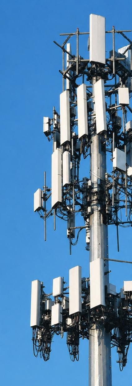
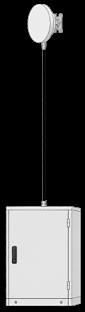
Across existing towers and rooftops, operators are layering new technologies onto existing infrastructure. What began as centralized 2G and 3G systems with long coaxial feeders and groundbased radios has evolved into 4G distributed radio architectures, with equipment located at the tower top. Today, 5G deployments rely more heavily on fiber, higher power density, and hybrid fiber and power solutions.
It isn’t a clean transition from one generation to the next. All legacy systems run concurrently and with 6G on the horizon, demands on space, power, and performance are continuously increasing.
To operate effectively in this environment, macro site infrastructure must address three critical challenges:
• Support multiple technologies simultaneously
• Maximize performance within limited space and physical constraints
• Maintain reliable operation over long deployment lifecycles
REAL-WORLD DESIGN. BUILT TO LAST
In macro site environments, performance is not defined at the point of specification. It is determined by how consistently solutions perform after deployment.
Installation plays a huge part in performance, making product design critical. Macro site operators need solutions that meet the highest technical and safety standards and are easy to fit, so inefficiencies aren’t introduced during installation. To minimize ongoing maintenance and maximize ROI, long-term performance is also critical.
RFS macro site solutions are designed to meet all of these demands, combining optimal performance with designs that support practical deployments and long-life span.
MACRO SITE CONNECTIVITY INTRODUCTION
RFS APPROACH
RFS provides a complete macro site solution across RF, FTTA, and PTTA, covering all infrastructure between the antenna and the base station.
Flexible, Customizable Topologies
Our portfolio spans cables, connectors, jumpers, and distribution boxes, designed to support the full range of macro site topologies from traditional feeder-based deployments to modern fiber and hybrid architectures. We also offer customized solutions to meet specific customer requirements.
Optimized Performance
RFS solutions are built to last. Each element is engineered for consistent performance and long life, ensuring reliable operation regardless of configurations, site constraints, and deployment conditions.
Field-installation Ready
Solutions are designed for practical implementation, with configurations that align with real site requirements and support efficient installation. This reduces deployment complexity and helps maintain performance from installation through long-term operation. We also offer solutions designed to meet requirements for a range of industry standards, from CPR for fire safety, to FRMCS for our transport customers.
Ongoing Support
RFS supports customers across the end-to-end process from systems design to installation and beyond. With online installation resources, planning tools such as the RFS Jumper Performance Tool, and dedicated technical expertise, RFS provides the support needed to ensure confidence at every stage.
This Brochure Covers:
• Configurations for a wide range of macro site topologies
• Portfolio highlights across RF, fiber, power, jumpers, and accessories
• RFS’s installation-focused design that protects performance
• Proven safety and sustainability standards
Brochure
Transportation
For more on how RFS is supporting transportation customers with the transition to FRMCS, visit our Future Transportation Brochure.
MACRO SITE TOPOLOGIES
INTRODUCTION
FLEXIBLE SYSTEMS FOR EVERY SCENARIO
Each macro site presents different constraints in layout, access, and equipment placement.
In the next section, we look at the extensive range of solutions offered by RFS that allow customers to select an installation approach that aligns with their specific site requirements across RF, fiber and power with a full range of tools and accessories for a complete solution.
RF
High-performance feeder cables, jumpers, and installation accessories engineered for low PIM and minimal attenuation to ensure consistent, optimal RF performance across the entire signal path.
Fiber
End-to-end fiber connectivity solutions, including cables, patch cords, transceivers, and panels, designed for high-speed, low-loss data transmission and flexible, future-ready configurations.
Power
Reliable power and grounding solutions, including cables, connectors, and grounding kits, designed to ensure electrical safety, lightning protection, and compatibility with radio systems from all major OEMs.
Microwave Backhaul
Elliptical, flexible waveguides, connectors and installation accessories for microwave connectivity between antenna and radio.
Accessories
Comprehensive range of RF and fiber accessories, including jumpers, clamps, grounding kits, and sealing solutions, designed to support reliable installation and long-term performance.
Installation Tools
Precision installation tools for cable preparation and connector assembly, for consistent installation quality that maintains performance.
QUICK START GUIDE
Standard RF Feeder Application Discrete Fiber & Power Application
RF feeders and connectors linking ground-based and tower-mounted equipment.
Page 8
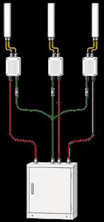
Connects each RRU directly to the BBU using separate fiber and power cables for a simple and flexible setup.
Fiber Application
Uses pre-terminated trunk cables that connect directly to jumpers, removing the need for distribution boxes at the top of the tower.
Page 10 Page 12
Application
Fiber & Power Application
Uses distribution boxes at different points on the tower to manage fiber and power connections between trunk cables and RRUs.
Page 14 Compact Distributor Fiber & Power Application
Combines fiber and power distribution in a compact unit near the radios to simplify cable routing and installation.
Page 16
Routes fiber through a protected distribution box while power is delivered separately, creating a structured and reliable setup.
Page 18
Elliptical, flexible waveguides and connectors, designed for low-loss, high-frequency transmission and reliable performance across microwave links.
Page 20
STANDARD RF FEEDER APPLICATION
Microwave Application (Page 20)
Fiber Cable to the Core Network
Power Connection / Backup Power BBU /
PSU
Jumpers (Page 22)
RF
Passive Antenna
STANDARD RF FEEDER APPLICATION
THE SOLUTION
RF Topology
All macro sites require an RF connection between the base station equipment and the antennas mounted on the tower. Feeder cables carry the signal over long distances, where low attenuation is critical to maintain overall system performance.
Connectors provide the interface between the cable and the equipment and must ensure consistent electrical and mechanical performance, while being practical to install in the field.
All elements must meet CPR and relevant safety standards, while also delivering reliable long-term performance in outdoor environments.
THE PRODUCTS
RF CONNECTORS
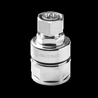
RFS OMNIFIT® connectors are designed for consistent electrical performance and reliable mechanical connections on macro sites.
• Compact form factor with low PIM and high-power handling
• Supports frequencies up to 6 GHz
• Compatible with all CELLFLEX® cables for flexible deployment
RF FEEDER
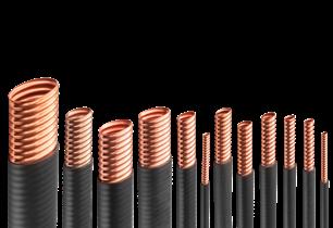
RFS CELLFLEX® cables support high-power transmission and stable RF performance across macro site frequencies.
• Low attenuation minimizes signal loss over long vertical runs
• Corrugated outer conductor for flexible installation and mechanical stability once deployed
• Meets CPR and fire safety standards and is designed for longterm outdoor operation
JUMPERS, ACCESSORIES & INSTALLATION TOOLS
A full range of jumpers, accessories and installation tools can be found on page 22 onwards.
Active Antenna
DISCRETE FIBER AND POWER APPLICATION
Fiber Cable to the Core Network
Base Band Unit (BBU)
PSU
Power Connection / Backup Power
Passive Antenna
RF Jumpers (Page 22)
Remote Radio Head (RRH)
DISCRETE FIBER AND POWER APPLICATION
THE SOLUTION
Discrete Topology With or Without Active Antennas
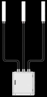
The discrete topology uses separate fiber and power cables to establish a direct connection between the RRHs and BBUs. This straightforward approach ensures a flexible and reliable installation while keeping the system design simple.
In this configuration, each radio is connected individually, making it easy to adapt to different site layouts and requirements. The solution supports both active and passive antenna systems without the need for additional distribution components.
This results in an efficient and easy-to-install solution for a wide range of deployments. All standard connectors are available for FTTA and PTTA applications.
THE PRODUCTS
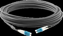
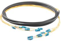
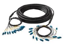
DISCRETE FIBER CABLES
Discrete Fiber Cables provide direct connectivity between the Remote Radio Head (RRH) and the Base Band Unit (BBU). These cables are typically used for shorter-distance connections, ensuring reliable, high-speed data transmission between network components. However, they are also available in extended lengths to accommodate a range of installation requirements.
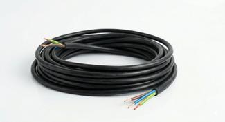
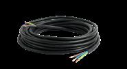
DISCRETE POWER CABLES
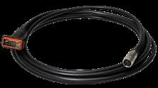
Discrete power cables are the counterpart to discrete fiber cables on an FTTA/PTTA site. It delivers power from the BBU to the RRH that is essential for site operations.
Fiber Cable to the Core Network
Power Connection / Backup Power
BOX LESS FIBER APPLICATION
Antenna
RF Jumpers (Page 22)
Remote Radio Head (RRH)
Discrete Power Cable (Page 10)
BOX LESS FIBER APPLICATION
THE SOLUTION
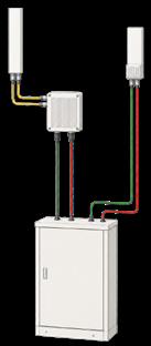
The box less application allows a direct connection between the trunk cable and the jumpers. This reduces costs.
In this case, the jumpers are directly equipped with the AOPC for the Nokia radios. However, the jumpers are also available with a FULLAXS for Ericsson radios or with a simple LC duplex.
The connection between the trunk cable and the jumpers is made with an ODVA connector, which does not require the use of any additional tools. A so-called Quick Lock connector is also available, which establishes the connection by simply plugging it in and snapping it into place.
THE PRODUCTS
FIBER JUMPERS
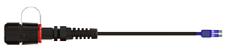
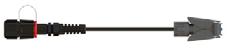
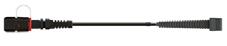
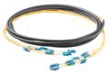
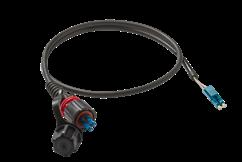
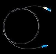
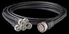
The fiber jumpers are pre-assembled with the ODVA connector on one end that connects directly to the trunk cable. On the other end there is a choice of different connectors (LC Duplex, AOPC, NSN Grommet or a FULLAXS) to suit RRHs from a range of OEMs and enable a clean and fast installation.
FIBER TRUNK CABLE
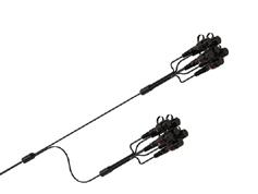
This pre-assembled “plug-and-play” cable is terminated with multiple ODVA connectors, eliminating the need for a box on top of the roof or tower. It connects directly to the jumper, which then interfaces to the radio for an easy and quick-to-deploy installation.
BOX TO BOX FIBER AND POWER APPLICATION
RF Jumpers (Page 22) Antenna
Remote Radio Head (RRH)
BOX TO BOX FIBER AND POWER APPLICATION
THE SOLUTION
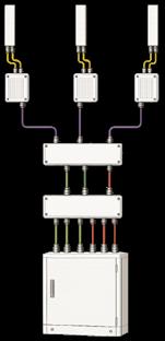
The box-to-box application is designed for single mode and multi mode in one system.
However, this system can also be operated with pure single mode or pure multi mode. The box has 16 pairs of fiber adapters and 8 pairs of power terminals.
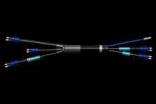
The jumpers from the top box to the radios are available as hybrid versions. Each hybrid jumper has 1 pair of power and 2 pairs of fiber. The jumpers are prepared for Ericsson, Nokia, or HW radios from the fiber side.
The jumpers from the bottom box into the BBU are available as a separate solution.
THE PRODUCTS
HYBRID JUMPERS
The top jumper in this setup is a hybrid jumper with one pair of power and two pairs of fiber. This allows each RRU to be connected with only one cable directly from the Box.
DISTRIBUTION BOX
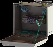
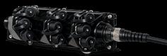
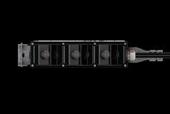
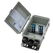
This box covers up to 16 pairs of fiber and 8 pairs of power. It can also be used as a box-to-box solution if required. This box is designed with a number of practical features that make it an efficient and reliable solution for installation on macro sites.
TRUNK CABLE
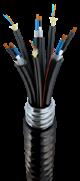
With this solution, you can use a combined hybrid solution, or a separate singlemode fiber trunk and a separate power trunk, depending on requirements.
BOTTOM JUMPER
The bottom jumper can be used as a separate jumper or as a combined jumper with multiple pairs of fiber, as well as power.
COMPACT DISTRIBUTOR FIBER AND POWER APPLICATION
Antenna
RF Jumpers (Page 22)
Remote Radio Head (RRH)
COMPACT DISTRIBUTOR FIBER AND POWER APPLICATION
THE SOLUTION
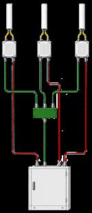
The compact distributor solution integrates fiber and power distribution into a single, space-saving design. By placing the distribution close to the radios, it reduces cable routing complexity and minimizes installation time.
In this configuration, trunk cables are connected to a compact distribution point, from which individual jumpers are routed to each RRH. This organized approach simplifies cable management and supports a clean and structured site layout.
The solution is designed for quick and efficient deployment, with pre-terminated connections enabling fast installation and reduced on-site work. It also supports a wide range of OEM interfaces, ensuring flexibility across different network requirements.
THE PRODUCTS
FIBER JUMPERS
The fiber jumpers are pre-assembled with the ODVA connector on one end that connects directly to the trunk cable. On the other end there is a choice of different connectors (LC Duplex, AOPC, NSN Grommet or a FULLAXS) to suit RRUs from a range of OEMs and enable a clean and fast installation.
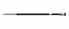
POWER JUMPER
The power jumper is ready to connect to the power box attached to the power trunk cable and, on the other end, fitted with a power connector for different OEMs.
FIBER TRUNK
The fiber trunk has a box direct mounted on top of the cable. Contains up to 12 pairs of fiber.
POWER TRUNK
The power trunk also has the box directly mounted on top of the cable.
Fiber Cable to the Core Network
Power Connection / Backup Power
TOP FIBER BOX APPLICATION
Antenna
RF Jumpers (Page 22)
Remote Radio Head (RRH)
Discrete Power Cable (Page 10)
TOP FIBER BOX
APPLICATION
THE SOLUTION
The Abel solution uses a dedicated fiber distribution box to manage connections between the trunk cables and the radios. This approach provides a structured and reliable installation while protecting critical fiber connections in outdoor environments.
Connections to the RRHs are made using pre-terminated jumpers, enabling fast and consistent installation. The solution supports a range of connector interfaces, ensuring compatibility with different OEM equipment and simplifying deployment across various site requirements.
THE PRODUCTS
FIBER JUMPERS
The Top Jumper connects the Fiber box and the radio. The RRH side of the jumper is fitted with a Uniboot connector, which can be used for the HW RRH and with an AOPC adapter or a FULLAXS adapter for Nokia and Ericsson RRUs.
FIBER BOX
In this solution, the fiber is routed through a dedicated spaceoptimized fiber box. This box is available in both 6-pair and 12pair configurations. The enclosure is IP67-rated, providing reliable protection against water ingress and ensuring safe operation in outdoor environments.
FIBER TRUNK CABLE
The fiber trunk cables are designed to fit perfectly with the box solution, supporting both 6-pair and 12-pair configurations.
MICROWAVE APPLICATION
Fiber Cable to the Core Network
Power Connection / Backup Power
RF Jumpers (Page 22)
Passive Antenna
Microwave Antenna
Microwave Antenna
Twistflex ODU
IDU
THE SOLUTION
Depending on the available frequency band and required capacity, full indoor, split mount, or full outdoor installations are possible.
Full
Indoor Installation
Transceiver is located at ground level, with high-frequency, high-power signals transmitted to antennas on top of the tower via elliptical waveguides.
Split Mount
Installation
Signal processing is at ground level in the Indoor Unit (IDU). The Outdoor Unit (ODU) positions high-frequency components on or near the antennas on top of the tower. Twistflex or short elliptical waveguides are used for antenna connection to allow easy access during maintenance. The ODU and IDU are connected via RF coaxial or fiber.
Full Outdoor Installation
ODU combines signal processing and high-frequency/power components into one unit at the top of the tower. Twistflex or elliptical waveguides are used for antenna connections, allowing easy access to the ODU or enabling multiple ODUs to be connected to a single antenna.
THE PRODUCTS
ELLIPTICAL WAVEGUIDES
FLEXWELL® waveguides are the market’s lowest attenuation waveguides for 4–40 GHz applications. Seamless welding and corrugated construction enable flexibility, and the PE jacket is suitable for harsh environments.
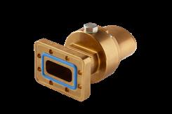
CONNECTORS
Field-installable connectors optimized for FLEXWELL® waveguides, available with multiple interface options to support all connection requirements.
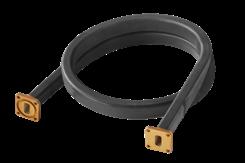
FLEXIBLE, RECTANGULAR WAVEGUIDES
Twistflex waveguides covers 3–40 GHz and are available in 600, 900, and 1200 mm lengths with various flange combinations for cost-effective installation and optimum performance.
A Complete Accessory Portfolio
Alongside its cable solutions, RFS offers a comprehensive range of RF and fiber accessories for macro site installations.
The following sections highlight key accessory groups used across RF and fiber topologies.
For the full portfolio, visit the RFS website.
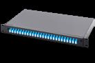
Optical Transceiver Patchcords
19”-Rack Products
RF Jumpers MQ4 / MQ5 AISG Cable
Grounding Kit
Hoisting Grip
Cable Clamps
19” Patch Panel
GENERAL ACCESSORIES
RFS cables are supported by a comprehensive range of accessories for seamless compatibility and to meet the full range of current industry requirements.
RF JUMPERS
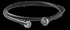
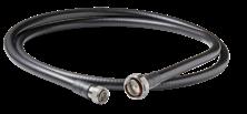
RFS RF jumpers provide flexible, pre-terminated connections between feeder cables, radios, and antennas with consistent, highperformance electrical characteristics.
• Factory-assembled and tested for defined VSWR and low PIM
• Standard connectors: 7/16 DIN, 4.3-10, N, and NEX10
• Ensures consistent performance vs field-assembled cables
• Supports a wide range of macro site configurations
AISG SYSTEM CABLE ASSEMBLIES
Assemblies provide durable outdoor connectivity between the antenna control unit (RET) and RRU, and between tower-mounted amplifiers, bias tees, and network control interfaces.
• Rugged design for reliable long-term outdoor performance
• Available in flexible lengths 0.3 m – 100 m
• AISG-standard connectors, including AISG and DB9 interfaces
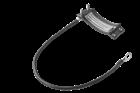
GROUNDING KITS
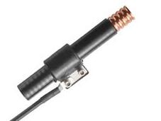
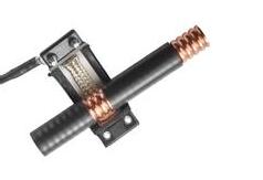
GKSPEED High-Speed Grounding Kits provide fast, reliable lightning protection and safe grounding with universal compatibility and tools for quick, clean installation
• Tin-plated copper mesh ensures low-resistance, secure contact without extra sealing materials
• Works with both copper and aluminum conductors to simplify inventory
• Includes JSTRIP tool for quick, easy field installation
HOISTING GRIPS
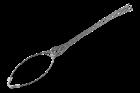
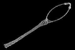
Hoisting grips are used to lift feeder cables from ground to antenna level, distributing force evenly to prevent damage and support easy installation.
• Mesh design spreads load to reduce stress on the cable jacket
• Ideal for long or heavy feeder cable runs
• Available in open/closed types for different installation processes
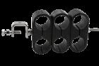
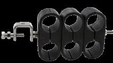
RFS Multi-Block Hanger (MBH) systems enable compact, organized routing of multiple coaxial cables with flexible configurations and fast, no-drill installation.
• Supports up to 3 (MBH) or 6 (MBHS) cable runs via stacked blocks
• Adjustable rod and set screw fit various tower geometries
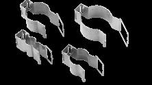
RSB Clamps
RSB clamps secure RF cables and jumpers near the antenna where standard mounts aren’t available, ensuring stable and flexible routing across site types.
• Ideal for final cable sections without C-rail mounting options
• Multiple clip sizes and linings fit various cable diameters
• Compatible fasteners enable secure attachment to different structures
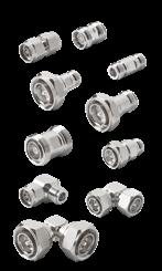
RF ADAPTERS
RFS coaxial adapters enable flexible interconnection between RF connector types while maintaining stable, low-PIM performance.
• Supports permanent and temporary connections across RF systems
• Available in straight/right-angle, 7/16 DIN, 4.3-10, and Type-N (male/female)
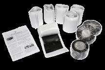
Where additional sealing is required, RFS offers a comprehensive range of solutions for reliable protection and compliance across all installation scenarios:
• Tapes: Tape wrap kits and self-amalgamating tapes for flexible sealing.
• Cold Shrink Tubes: Pre-expanded tubes for fast installation and reliable sealing.
• Heat Shrink Tubes: Durable sealing for cable and connector interfaces.
• Connector Interface Covers: Protective caps for unmated connectors.
GENERAL ACCESSORIES
RFS offers a comprehensive selection of fiber accesssories to support installation and enhance the performance of RFS’s fiber solutions.
A selection of the highlights is showcased in this brochure, with the full portfolio available on the website.
CLAMPS FOR FIBER CABLE
RSB or MBH clamps with linings enable safe, flexible routing of fiber cables alongside RF infrastructure.
• RSB or MBH clamps support fiber cables with added protective linings
• Linings accommodate different diameters without damaging fibers
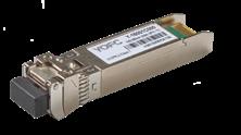
SFP modules (transceivers) are transmitter and receiver modules for high speed connections between base station equipment and network interfaces.
• Compact, hot-swappable modules for transmit/receive functions
• Standard interface for connecting switches, routers, and servers
• Multiple variants available for different distances and site needs
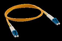
PATCH CORDS
Patch cords enable quick, flexible connections between optical or electronic network devices.
• Pre-terminated, flexible cables for fast deployment
• Designed for easy routing and frequent reconfiguration
• Available in various lengths, connectors, and APC/UPC options
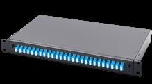
19” PATCH BOX (PATCH PANEL)
19” patch boxes provide centralized organization and connection of network cabling at macro sites.
• Manages fiber and copper connections in one location
• Connects RRH/RRU at the tower to BBU in the base station
• Supports multiple adapter types for flexible integration
INSTALLATION TOOLS
To make installation as straightforward as possible, RFS offers a range of installation tools to streamline the process and ensure clean, high-quality installations.
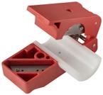
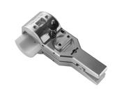
UNIVERSAL TRIMMING TOOL
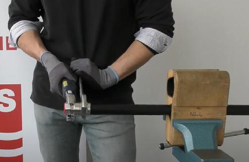
Universal Trimming Tools prepare coaxial cables for connector installation with a fast, all-in-one trimming process.
• Combines trimming, deburring, chamfering, and flaring in one tool
• Preset blades ensure precise preparation of conductor and dielectric
• Interchangeable inserts support multiple cable sizes and connector types
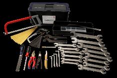
TRIM-T01 TOOLBOX (HAND TOOL KIT)
The TRIM-T01 toolbox provides a complete set of tools for manual installation of OMNI FIT™ connectors on CELLFLEX® cables.
• Covers cable sizes from SCF14 to LCF158 for broad applicability
• Works best when combined with trimming and stripping tools
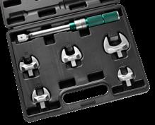
TRIM-T05 TORQUE KEY SET
The TRIM-T05 Torque Key Set ensures precise and consistent connector tightening for optimal performance.
• Designed for OMNI FIT® Premium E01 connector installation
• Applies correct torque to ensure electrical reliability
• Helps maintain long-term performance and installation quality
PRODUCT
DESIGNED FOR FIELD INSTALLATION. BUILT FOR PERFORMANCE.
THE COST OF A POOR CONNECTION IS HIGH.
A single issue can require additional site visits, cable replacement, and additional labor. Unresolved, it limits network performance and reliability. In many cases, the cost of remedial work far exceeds the cost of getting installation right the first time.
Every connection, routing decision, and assembly step directly impacts how the system performs. Variations in connector preparation, grounding, routing, or handling can introduce inconsistencies that affect overall system performance.
RFS has designed solutions with field installation in mind to ease rollouts, reduce poor installations, and ensure consistent results across deployments.
Designed with Installers in Mind
RFS solutions are developed with direct input from installation teams.
• Specialized tools for clean installations
• Simplified connector preparation and assembly
• Reduced potential for installation errors
By including installation considerations at the design phase, RFS helps teams roll out macro site installations efficiently and with confidence.
Supporting Installation at Every Step
RFS supports installation teams with:
• In-person training and online installation videos
• Clear documentation and best practices
• Access to dedicated technical experts
Providing the tools and knowledge required to achieve consistent installation quality.
RFS
•
•
•
INSTALLATION VIDEOS
CUSTOMIZABLE FOR OPTIMUM PERFORMANCE
RFS solutions are fully configurable, so installation approaches align with specific site requirements. This supports efficient deployment across different topologies without unnecessary complexity.
UK Italy
CASE
STUDY: A CUSTOMIZED SOLUTION, OPTIMIZED FOR INSTALLATION
Overview
A Tier 1 operator needed multiple customized macro site components as part of the transition to new OEM infrastructure. What started with customized hybrid jumpers became a full solution for power and fiber, designed to be practical and fast for installers to deploy.
Solution
Working with the operator, installers, and new OEMs, RFS developed a tailored architecture combining power trunks, fiber trunks, hybrid jumpers, and breakout boxes. RFS provided custom cables to meet higher power requirements, while hybrid jumpers reduced the number of separate runs. Breakout boxes were developed with installer-led design features, including pre-fitted brackets, improved internal layouts, and secure bungs for ease of installation.
Result
The custom design met every technical requirement and shortened installation time. RFS also worked with partners to offer a single-supplier model, streamlining sourcing of all passive components for installers and improving efficiency across deployments.
CASE
STUDY: A CUSTOMIZED SOLUTION FOR A TIER 1 OPERATOR
Overview
RFS partnered with a Tier 1 operator in Italy to address fronthaul connectivity challenges for 5G macro sites in Italy, where space, performance, and scalability are critical. The customer required a compact, easy-todeploy solution capable of delivering both fiber and power, while supporting future network evolution.
Solution
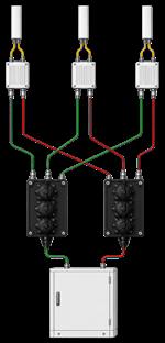
After running multiple trials with the operator, RFS developed a customized approach using two discrete multi-riser trunks; one for DC power and one for optical fiber, terminated with compact distributors. This removed the need for bulky tower-top cabinets and simplified installation.
Result
The flexible design reduced site footprint, enabled fast deployment, and allowed seamless future upgrades via jumper connections, giving a high-performance, futureready solution to support ongoing 5G expansion.
GREEN BY DESIGN
SUSTAINABLE CREDENTIALS
It is more important than ever to both us and our customers that projects are designed with sustainability in mind.
The R&D teams at RFS are committed to ensuring our solutions support our customers’ green ambitions, and this extends across our range of indoor solutions.
As an organization, we are making positive changes to continue to move towards our own net-zero targets and support customers. To achieve this, we have an environmental strategy based on four key principles:
01 - GREEN BY DESIGN
• Design for Environment (DfE): This is part of the Product Lifecycle Process, with all products undergoing our RFS Product Carbon Footprint Life Cycle Assessment
• Material Efficiency: We manufacture using the minimum raw materials to reduce environmental impact without compromising quality. For example, our connectors are manufactured as a single piece, making one of the greener solutions on the market.
• Power Efficiency: Our engineering team has focused on ensuring low attenuation in our products. Not only does this give better performance, but leads to reduced power consumption.
02 - SMARTER LOGISTICS
• Global Network: With key hubs in Europe, Asia, and an exclusive North American distributor, we maintain a short and efficient supply chain.
• Sustainable Delivery: For smaller orders via RFStore, we collaborate with local couriers to minimize environmental impact and avoid partial load deliveries.
• Drum Recycling Program: Our buy-back program encourages customers to return cable drums for recycling or reuse.
03 - BUILT TO LAST
• Future-Proof Technologies: Our systems are designed with future needs in mind.
-
SUSTAINABLE MANUFACTURING
• Recycling Initiatives: We recycle copper, aluminum, brass, scrap metal, and electronics left over from manufacturing to minimize waste.
• Environmental Projects: Across our sites, various initiatives, including using solar power and recycling rainwater for cooling, help reduce the carbon footprint of manufacturing.
• Global Compliance: All RFS facilities meet globally recognized environmental standards, including ISO14001 Environmental Management
• Long Life: Long-lasting equipment is key to reducing environmental impact. There is a reason our motto is ‘Lifetime Connectivity’. In 2023, RFS launched a major project to install solar panels on the roof of our Suzhou factory. Covering 16,000 square meters, the panels can generate 1.49MW of power. The project is expected to see an annual power generation 1.35 million kWh and save an estimated 1346 Tons of CO2 annually. In January 2024, the project was successfully connected to the state grid for power generation, meaning any excess energy can be utilized beyond our Suzhou factory, extending the positive environmental impact of RFS.
RFS CABLE MADE WITH GREEN ENERGY
SAFETY IS KEY CPR
ROBUST JACKET CONSTRUCTION ENABLES THE HIGHEST CPR CLASSIFICATIONS
RFS CPR-compliant coax and radiating cables feature a specially developed jacket that allows them to achieve best-in-class ratings for burning droplets (d0), low smoke emission (s1) and corrosivity (a1), the most important criteria for fire safety in cables that are installed indoors and underground.
All RFS cables are tested and certified by an external notified body according to EN 50575. In addition, RFS’ manufacturing facility in Hannover, Germany, has been audited and meets the highest system 1+ requirements for type approvals, regular production audits, as well as regular sampling and testing of products by the notified body.
FIND CPR-COMPLIANT CABLES FOR ANY APPLICATION
All RFS CPR-compliant cables are also designated as low-smoke, zero-halogen (LSZH) and meet International Electrotechnical Commission (IEC) standards for flame spread, smoke acidity and low smoke emission. They are compatible with existing RFS connectors, factory-assembled jumpers, grounding kits and clamps, as well as trimming and preparation tools.
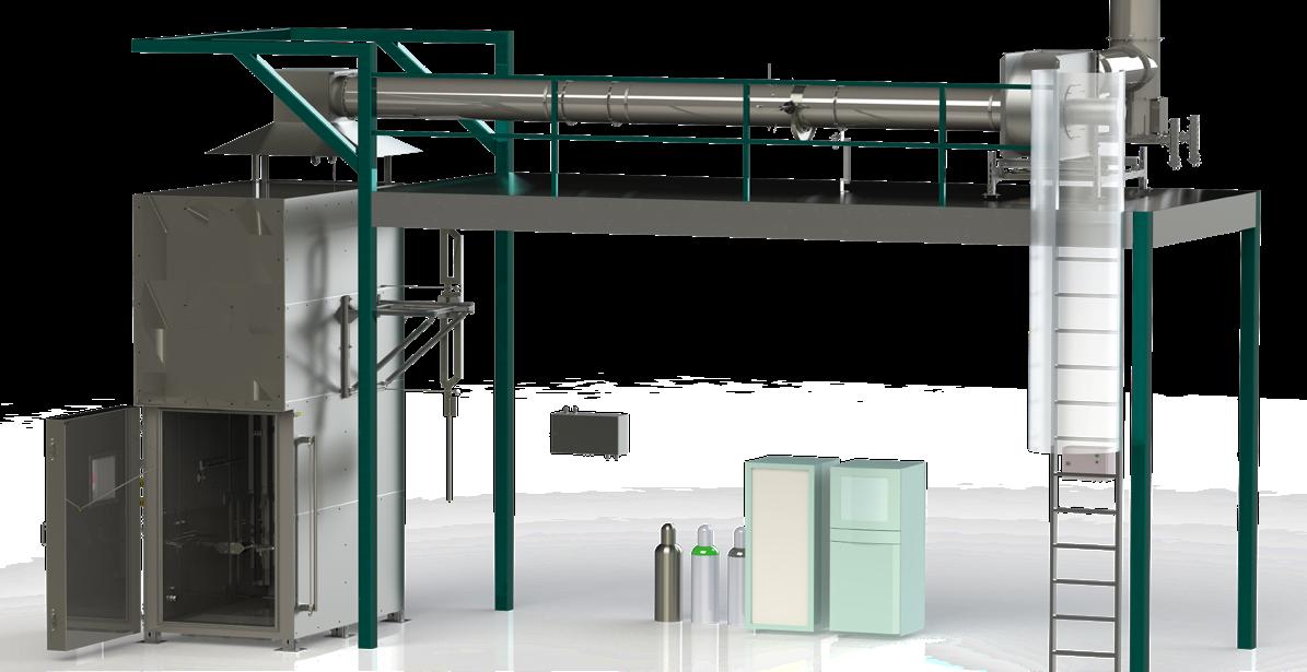
NEW RFS HANNOVER BURN CHAMBER
The in 2024 installed burn chamber extends RFS's testing capabilities and operates in accordance with the international standard EN50399 which refers to the important CPR (Construction Product Regulation) directive of the European Union. Combined with existing fire testing facilities, it gives RFS one of the most comprehensive in-house fire resistance testing capabilities of any organization in the cable space. This will allow RFS to continue offering solutions that meet fire safety standards worldwide.
EUROPEAN CLASS CODE LABELING EXAMPLE
This table explains the CPR class codes using the rating for our CELLFLEX cables as an example: B2ca s1 d0 a1.
CPR-COMPLIANT CABLES ARE IDEAL FOR INDOOR APPLICATIONS
A BROAD PORTFOLIO OF CPR-COMPLIANT CABLES FOR INDOOR APPLICATIONS
Since July 1, 2017, all communications cables installed in buildings in the European Union (EU) must meet the fire performance requirements in European standard EN 50575 and include the CE marking to comply with EU Construction Products Regulation (CPR) No. 305/2011.
RFS was the first cable vendor to offer RF communications cables with the highest CPR classifications for fire safety. Today, we offer a wide range of CELLFLEX® coaxial cables and RADIAFLEX® radiating cables that comply with European CPR No. 305/2017. This directive requires that coax and radiating cables meet the fire performance standards in the EN 50575 standard and be classified according to the EN 13501-6 standard.
RFS cables are classified according to the CPR test standards and criteria listed below.
The CPR burning droplets classification is particularly important because burning particles can ignite other cables or infrastructure. Only class d0 cables create no burning particles to deliver the highest levels of fire protection in buildings and tunnels.
CPR CLASSIFICATION
B2ca: +++ Cca: ++ Dca: + Eca: -
RADIO FREQUENCY SYSTEMS
Why RFS?
RFS brings together long-standing expertise, and a practical understanding of what networks need to perform both today and in the future:
Heritage you can rely on: More than 125 years of engineering excellence and continuous innovation
Trusted in the field: A global leader in RF technology, proven across real-world deployments
Built for modern networks: Deep knowledge of RF, FTTA and PTTA solutions for evolving macro site architectures
Complete portfolio: A single, trusted partner for indoor and outdoor connectivity solutions
Local Manufacturing: Production in Europe (Germany) and Asia (China) for consistent quality and supply assurance
Focused on your challenges: Solutions designed around real-world challenges and operator needs
Adaptable design: Flexible configurations that meet local requirements and site conditions
Safety as standard: Fire safety products engineered to meet the highest international benchmarks
Committed to sustainability: Strong sustainability framework to ensure solutions that are green by design
Ready for what’s next: Infrastructure designed to support upgrades and future technologies without disruption