Safety Instructions
Read this manual thoroughly before starting-up or operating the equipment, and prior to maintenance or any other types of operations.
Strictly comply with all warnings, danger notes, cautions specified in this manual and safety labels affixed directly on the machine.
Operators shall master all necessary operation skills for this equipment; maintenance work must only be performed by qualified technicians.
Remove the aggregates from the machine before any cleaning or maintenance work.
Stop the machine and wait for the aggregates to cool down before any lubrication or maintenance procedures.


Paragraphs marked with this symbol indicate imminent hazards. Their contents must be observed carefully to prevent serious accidents.
Paragraphs marked with this symbol specify procedures and actions to be followed so as to avoid any damage to goods and property.

Paragraphs marked with this symbol highlight exceptionally important points that shall not be overlooked.


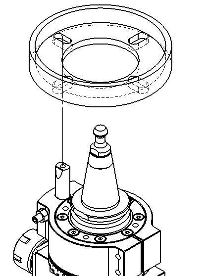
Mount the aggregates onto the lock pin flange or automatic orientation device (C-axis) of the motor spindle. The aggregates shall be fitted with a guide pin matching the corresponding housing. When mounting the aggregates onto the motor-spindle for the first time, you have to adjust the locking pin (refer to the following content) to achieve perfect fitting with the housing.









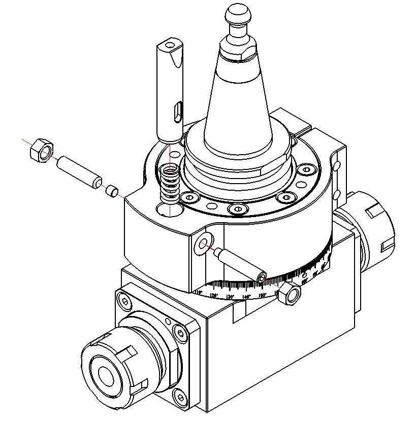
1、 Unscrew lock nut (F); do not fully loosen locking screw (D). The spring (B) will push lock pin (A) upward to its top limit. Do not fully loosen guide screw (C) to prevent the pin from ejecting; ensure the pin only moves within the housing. The factory preset positions of (C) and (G) shall not be arbitrarily loosened or adjusted.
2、 Press lock pin (A) down to its bottom stop, then turn locking screw (D) to secure lock pin (A) at the lowest position. 3、 Mount the aggregates onto the motor spindle, aligning the lock pin with the motor spindle flange.
4、 Loosen locking screw (D) again to allow the lock pin to engage into the motor spindle flange.
5、 After verifying full engagement of the lock pin inside the housing, retighten locking screw (D) to secure the lock pin, then fasten lock nut (F).
Failure to adjust the locking-pin will cause rapid deterioration of the overall installation condition, which may result in a risk of separation from the motor-spindle.
3.1 Fixed-Type Aggregates Angular Adjustment
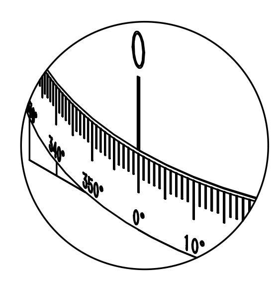
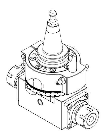
1、 Loosen the fastening screw (A) of the pin fixing base with a suitable wrench.
2、 Align the position between the output shaft of the aggregates and the latch pin by using the indicator line (B) on the pin-shaft fixing base and graduations (C) on the dial.
3、 Retighten the screw with a suitable wrench at a torque of 6 N·m.
The dial scale and housing are secured by set-screws. Do not loosen them arbitrarily.
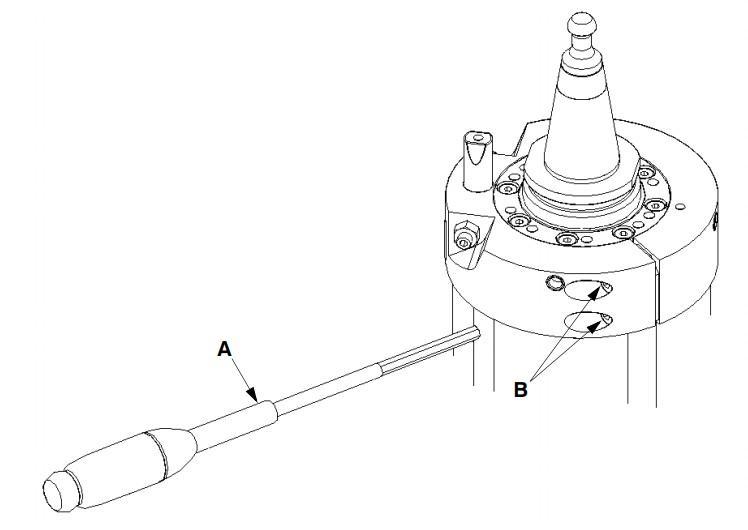

1、 Loosen the fastening screw (B) of the pin fixing base using a suitable wrench (A).
2、 Align the position of the aggregates output shaft and the latch pin via the scale (C) on the pin-shaft fixing base and the housing indicator (D).。
3、 Retighten the fastening screw with a suitable wrench at a torque of 6 N·m.
3.3 Angle adjustment (tilt direction) for adjustable aggregates
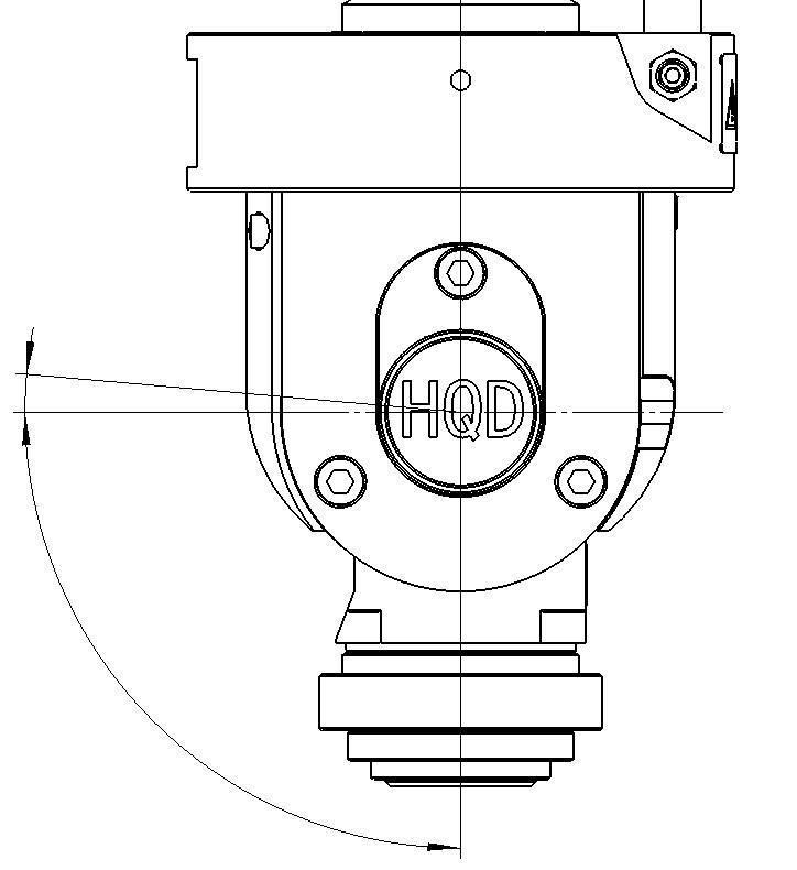
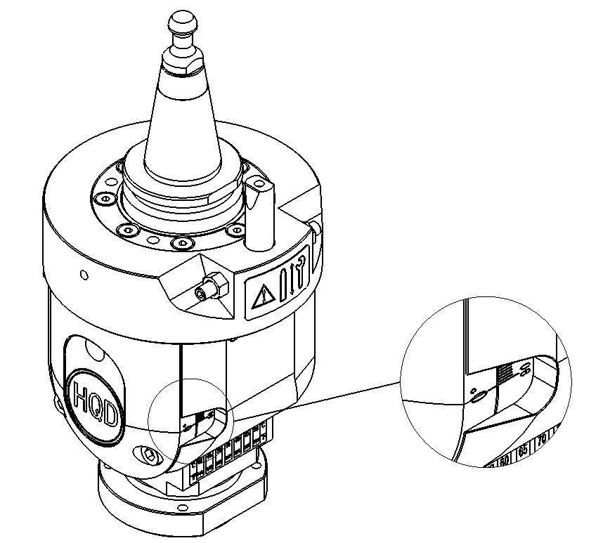
1、Loosen fastening screw (A) with a suitable wrench. 2、 Manually rotate the rotating part (B) and adjust its tilt angle by referencing the scale indicator (C). 3、Retighten the fastening screw with a suitable wrench at a torque of 6 N·m.
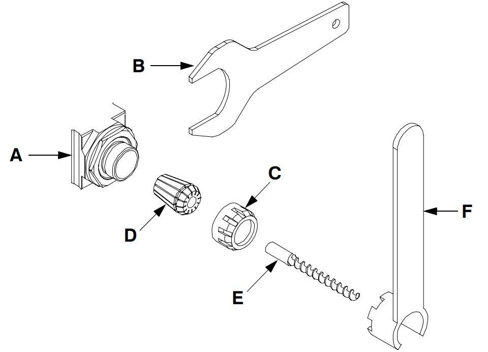
1、 Clamp and secure output shaft (A) with a wrench.
2、 Unscrew lock nut (C).
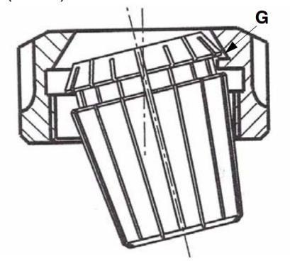
3、 Install collet (D) into the annular groove (G) of the lock nut.。
4、 Thread the lock nut back onto the output shaft without full tightening.
5、 Insert tool shank (E) into the collet.
6、 Tighten the lock nut with a suitable torque wrench (F) to the specified torque value.
Recommendation: Use a preset torque wrench to tighten to 80% of the maximum torque value.
5、Tool Installation Specifications
When an ER25 collet is fitted, the shank diameter of cutting tools installed inside the collet can range from Φ1 mm to Φ16 mm (A). The applicable length depends on the selected collet (B).
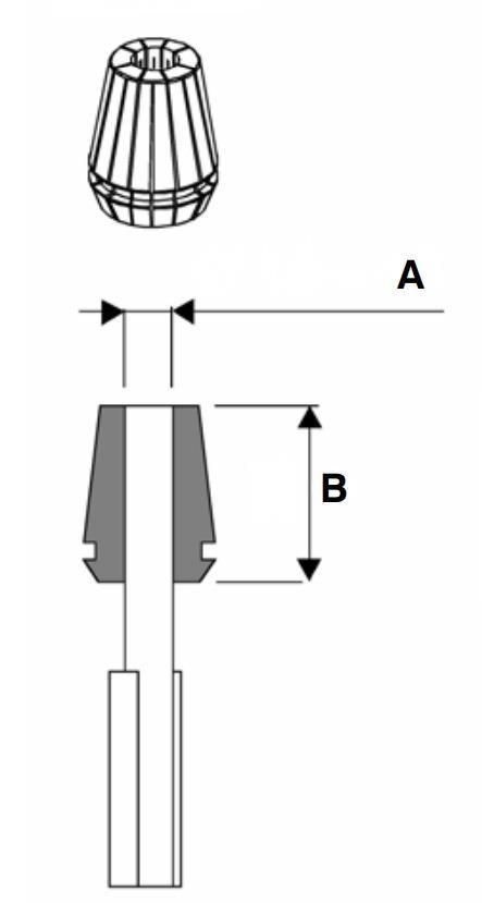
Unless otherwise specified in the technical data sheet, the tool tip diameter shall not exceed the maximum allowable shank diameter.
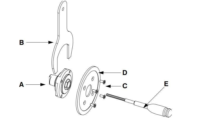
1、 Secure output shaft (A) with wrench (B).
2、 Fit saw blade (D) onto the output shaft, aligning the holes on the saw blade with the shaft holes.
3、 Tighten the 4 hexagon socket countersunk screws(C) with a suitable wrench at a torque of 5 N·m.
7、Operating Temperature
Continuous operation of the aggregates is permitted only if operating speed, temperature and cycle parameters comply with the specifications stated in the technical data sheet.
The temperature of the aggregates shall not exceed 70 °C.
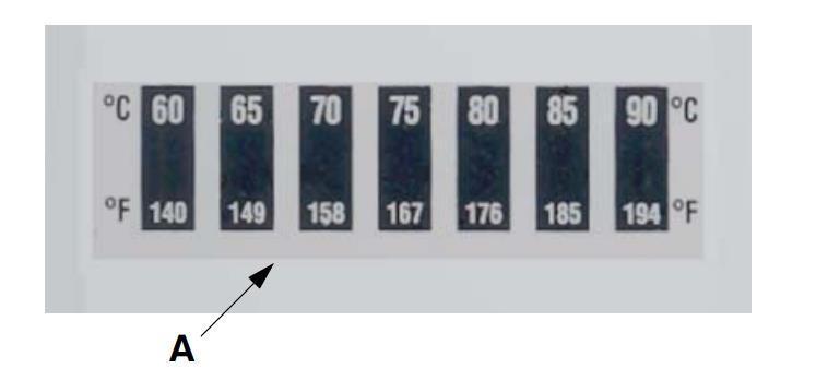
A temperature test strip (A) is affixed to the aggregates housing.
The temperature shall not exceed the limit value of 70 °C within one duty-cycle. If this threshold is exceeded nevertheless, extend the downtime and verify whether the aggregates receives proper maintenance.
Continuously monitor the aggregates temperature to prevent malfunction or component damage.
8、Lubrication
Do not eat, drink or smoke when handling grease. Observe all applicable safety regulations when handling oils and greases. Only use the designated lubricant specified below.
Regular and correct maintenance is required to maximize aggregates performance, maintain efficiency and extend service life. Compliance with lubrication intervals, use of approved lubricants and proper
operating conditions prevent stress concentration and premature failure.
The table below specifies lubrication intervals and lubricant types.
Lubricant
Designation Properties
KLUBER
ISOFLEX
NBU15
Type: Grease
Density:0.99 g/cm³(20℃
Melting Point:≥220℃
Lubrication
Interval
3 g grease every 100 operating hours
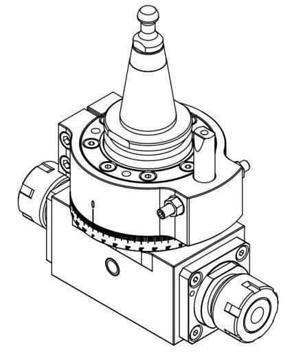
Note: The oil filling port location and required lubricant dosage vary by aggregates model.
Oil-filler port
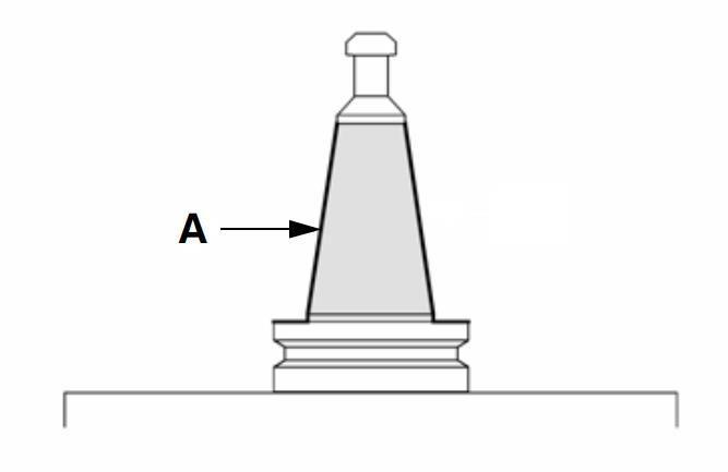
Wipe the taper surface (A) with a clean soft cloth dampened with industrial alcohol or trichloroethylene.
After cleaning, spray anti-rust agent (e.g. LUSIN PROTECT G31) onto surface (A) to prevent seizure between the taper and motor spindle and avoid damage to the tool changer mechanism.