17 minute read
CHAPTER 2: HELICAL PILE SYSTEMS � � � � � � � � � � � � � � � � � � � � � � � � � � � �

BUILDING STABILITY
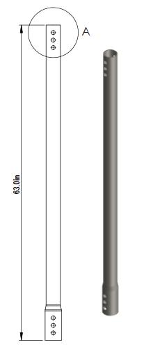
Figure 10 - Helical Pile Lead
Advertisement
Figure 11 - Helical Pile Extension
Helical piles have five main components: the lead section, extensions, couplings, helical plates, and a bracket or pier cap that allows attachment to the foundation of the supported structure. Figures 10 and 11 show typical helical lead section, extension and helix.
2�1 Basic Features of a Helical Pile
The basic features of a typical helical pile are shown in Figure 5. The lead section has the helices affixed to it. If needed, helices can also be affixed to the extensions. The lead section is the first section that gets screwed into the ground. Extensions are added until the minimum required torque and depth are met. The connection between the lead and extension sections is termed the coupling. There are many different types of couplings used in the helical pile industry. The most common coupling is the bolted coupling, used by Cantsink.
The helical pile components in Fig 5 (lead and extension) are screwed into the ground by the application of torque, and are extended until a desired depth or suitable soil or bedrock stratum is reached. A pier cap or bracket is used to attach the pile to the structure. Many different pier caps or brackets have been used throughout the helical pile industry, depending on the types of foundations they support.
2�1�1 Helical Bearing Plates or Helices
Cantsink Helix Plate: The helices are hexagonally shaped steel plates that are stamped into a spiral shape and welded to the lead or extension shaft sections (central pile shaft). Cantsink helical plates have a pitch of 3 inches. The helix spacing used, 3D spacing, is 3 times the leading helix diameter, and is commonly used in the helical pile industry. AC358 also allows a helix spacing of 2.4 to 3.6 times the helix diameter. This 3D spacing is an increment of the pitch, which allows the helices to track the same path during installation and therefore minimize soil disturbance. The smallest diameter helix is usually mounted to the leading end (tip) of the pile shaft with progressively larger diameter helices mounted above. Cantsink helices are corrugated helical plates (formed with radially stiffening ribs) that provide greater strength compared to the standard flat plate helix (see Appendix for helical plate capacities).
Helix geometry varies and depends on the specific application and project site specifics. All helices must have the same pitch. It is impractical to attach helices with different pitches on the same pile shaft because it will be difficult to screw into the ground and will produce excessive ground disturbance. It is common for installers to collaborate with helical pile manufacturers to develop helix geometry that can be used for specific projects with particular ground conditions. For small diameter helical piles (shaft size less than 4.5 inches), Cantsink helical plates are fabricated in accordance with the
standard geometric criteria described in Table 3 of AC358, which states the following:
• Helix bearing plate pitch is 3 in ± 0.25 in. • All helices must have the same pitch. • Helices are arranged such that they track the same path as the leading helix. • Helices should be normal to the shaft, such that the leading and trailing edges are within 0.25 inch of parallel. • For shafts with multiple helices, the smallest diameter helix shall be mounted to the leading end of the shaft with progressively larger diameter helices above.
Cantsink helical plates with equivalent diameters of 8, 10, 12 or 14 inches are 0.375 inches thick and 16- and 19-inch diameter helix plates are either 0.375 inches thick or 0.500 inches thick if they are over 80 kips. Cantsink helix plates conform to ASTM A36 steel with a minimum yield strength of 36 KSI and a minimum tensile strength of 58 KSI. The helix plate finish is either plain steel or hot-dip galvanized in accordance with ASTM A123, with a minimum coating thickness of 0.005 inches per side.
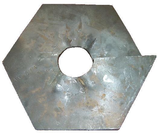
Figure 12: Helical Plate (Top View) Figure 13: Helical Plate (Side View)
2�1�2 Central Shaft
The shaft is the central element of a helical pile. It includes the lead section and the extensions needed to install the pile to the required torque and depth. The extension sections are available in shafts with and without helical plates. Cantsink provides both solid steel square (round corner square bar, RCSB) and round hollow (pipe) shafts. The length of the lead and extension sections range from 2 feet to 10 feet, which helps Cantsink’s piles when they are installed in tight spaces or confined areas with low overhead. Different lengths could be manufactured depending on the specific project requirements and client’s needs. The lead and extension sections of the round shafts are carbon steel round tubes that conform to ASTM A500, Grade B, having a minimum yield strength of 50 KSI and a minimum tensile strength of 65 KSI. The leads and extension sections of the RCS steel bar conform to 1530M2 and/or 1045M2, having a minimum yield strength of 85 KSI and minimum tensile strength of 100 KSI. For both square and round shafts, Cantsink provides lead and extension sections in either bare steel or hot-dipped galvanized in accordance with ASTM A123, with a minimum coating thickness of 0.005 inches per side.
Figure 14 2�1�3 Coupling
A coupling is used to connect the extension sections to the lead section or additional extensions to achieve the required depth. The coupling is designed and tested to carry the required installation torque and the designed structural loads. At Cantsink, the extension sections of the round shaft have a factory cold-formed, bell-shaped end segment to fit over the lead section or other extension sections. The connection of the extension sections to the lead shaft or other extension is accomplished by throughbolted connections using three, ¾-inch or ⅞-inch diameter steel bolts through the extension bell-shaped segment and the connected lead or other extensions. The bolts conform to ASTM A307 Grade A or ASTM F3125 A325, and the matching hex nuts conform to ASTM A563 Grade A or ASTM A194, Grade 2H. The extension sections of the 1.5-inch RCS shaft have a forged upset socket at one end of the steel bar, which allows the upper end of the lead shaft or other end without the upset socket of an extension to be fitted. The connection of the 1.5-inch RCS lead shaft and extension sections is accomplished by the through-bolted connection of a single ⅞-inch diameter bolt through the upset socket at the end of the shaft. For the 1.5inch RCS shaft, the bolts used conform to ASTM F3125 Grade A325, and the matching hex nuts conform to ASTM A563 Grade DH.
2�1�4 Structural Termination
Structural termination simply refers to the connection between the installed pile and the structure it supports. In the helical pile industry, depending on the application of the helical pile or anchor, there are generally two styles of structural termination at the foundation level: pile cap (or pier cap) and bracket. Pile caps are usually used for new construction. Custom variations of a pile cap are often made to allow for easier field attachment to different types of superstructures (wood, steel, concrete). Brackets are usually used for underpinning (remediation) applications.
1.25in
4.75in
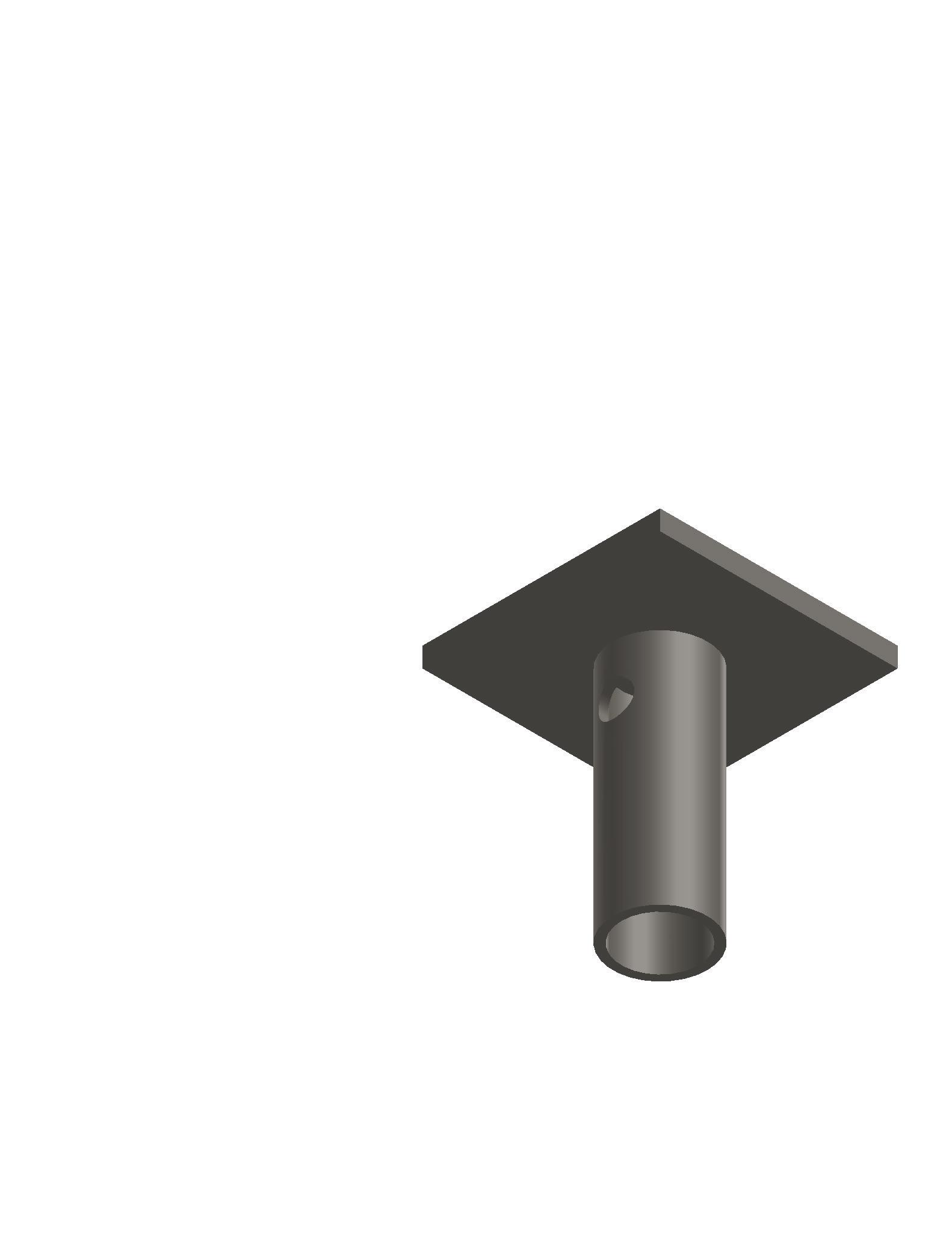
Figure 15 2�1�4�1 New Construction Bracket
For the 1.5-inch RCS shaft, a Cantsink new construction bracket is embedded into the concrete footing, grade beam or pile cap. The bracket consists of a 6-inch by 6-inch by 1/2-inch steel plate, factory welded to a 2.38-inch outside diameter steel round tubing with a nominal wall thickness of 0.218 inch and a length of 6 inches. The bracket comes with one predrilled hole used to receive one, ⅞-inch diameter bolt. The bolt conforms to ASTM F3125 Grade A325 and the matching hex nuts conform to ASTM A563 Grade DH. Bolts and nuts can be either bare steel or hot-dipped galvanized in accordance with ASTM A153.
For the 2 ⅞-inch HSS shaft, a Cantsink new construction bracket (NCB-TC) is embedded into concrete footing, grade beams or pile caps. The bracket consists of a 6-inch by 6-inch by 1/2-inch steel plate, factory welded to 3.5-inch outside diameter steel round tubing with a nominal wall thickness of 0.216 inch and a length of 6.5 inches. The bracket includes three predrilled holes used to receive three, ¾-inch diameter bolts. The bolts conform to ASTM F3125 Grade 307, and the matching hex nuts conform to ASTM A563 Grade DH. Larger brackets are available for larger pile shafts, helix and loads.
The new construction bracket steel plate conforms to ASTM A572 Grade 50, with a minimum yield strength of 50 KSI and a minimum tensile strength of 65 KSI. The round steel tubing conforms to ASTM A500, Grade B, and has a minimum yield strength of 50 KSI and a tensile strength of 65 KSI. The new construction bracket can be made either bare steel or galvanized in accordance with ASTM A123 and having a minimum coating thickness of 0.005 inches.
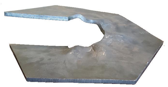
2�1�4�2 Underpinning Brackets
An underpinning bracket is an assembly of components used together to repair existing structures. These components are attached to the shaft of the pile that will transmit the load to the soil. The main body of the bracket is cut from square HSS 10x10x1/4-inch steel tubing. The 12-inches wide by 11-inches high steel shelf and supporting tabs are cut from ¼-inch thick ASTM A36 steel and are factory welded to the HSS main body. A lifting T-pipe consists of a rectangular HSS 3x2x1/4-inch steel tubing and a 2 3/8-inch outside diameter round steel tubing with a nominal wall thickness of 0.154 inch and a length of 48 inches.
Figure 16

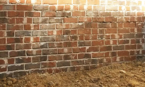
Figure 17
2�1�4�3 Slab Brackets
Slab brackets are similar to underpinning brackets. These are used primarily for the repair of interior spaces. Slab brackets were designed to allow hydraulic assist, which greatly increases the lifting capacity. This process places the support bolts close to the hole’s edge, and combined with a 6-inch channel, limits the lifting capacity to the punching shear of the floor. The Cantsink system uses a 6-inch x 13-inch channel in a 10-inch hole, with lifting points 6 inches apart. The limiting factor is the punching shear of an 18-inch long channel, which will extend 5 inches out from the hole on each side. From ACI-14 R13.2.7.2 for a 3.5-inch thick slab, we calculate that the shear perimeter where the slab will break is: 2[2(5.75” +1.875”) +9.5] = 49.5”. Multiplying that by the depth and shear strength of the slab, we get: V= perimeter x thickness x Vc, where Vc is the shear strength of the concrete and V is the allowable load on a 3.5-inch thick concrete slab. V = 49.5 x 3.5 x 2 x (3,000)1/2 = 19,000 lbs. For installation, a 10-inch hole is cored in the concrete slab for a bracket installation. Afterwards, dirt is removed one foot deep underneath the slab, with 6 inches excavated around the hole outward. The pile is installed and cut off a foot below the slab. The channel is slid into position under the slab, and a pile extension is then fitted into the pile and marked 1 inch below the slab, and then removed, cut, and reinstalled. The two lifting bolts are attached to the channel and fitted with the jacking bracket at the top. Lifting is completed and the nuts are tightened to the top. The hole is then patched.
2�1�4�4 Timber Brackets
Timber brackets can be used for boardwalks, decks, or elevated structures. They allow a structure to be built without the need for excavation or concrete footings, and work well in environmentally sensitive or flood prone areas.
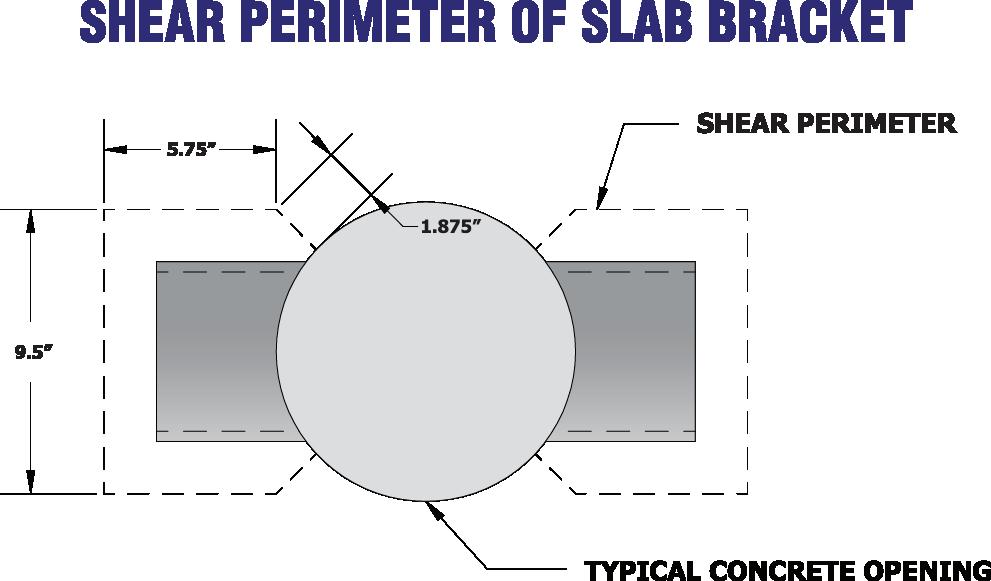
Figure 18
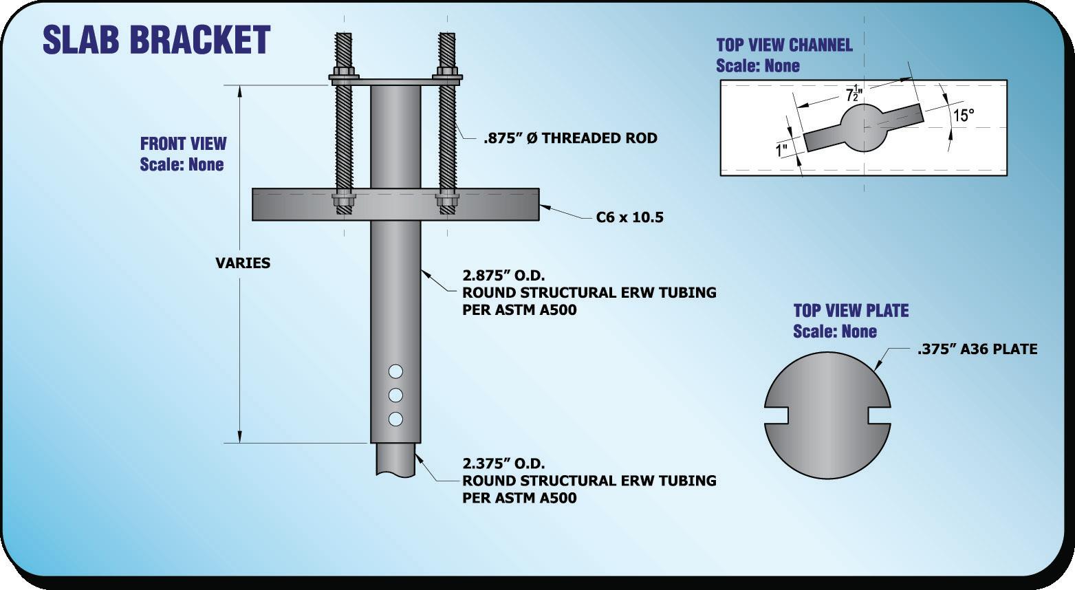
Figure 19
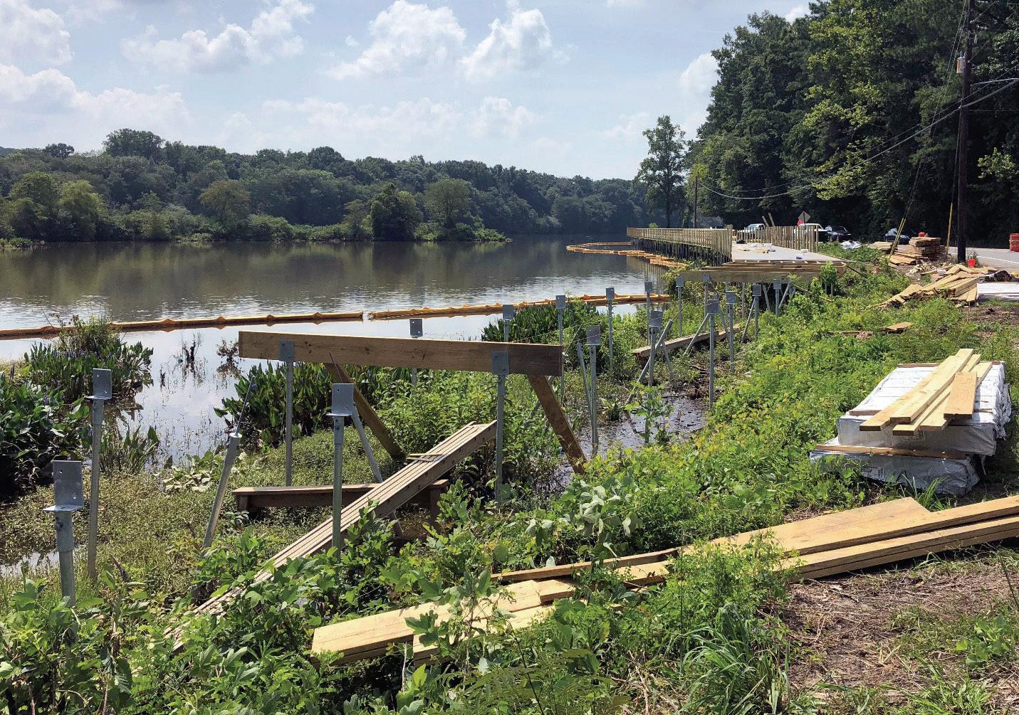
Figure 20 Figure 21

2�2 Helical Pile Installation
One of the most recognized benefits of using helical piles is their simple and quick installation, making them popular for many projects. The pile is installed into the ground, which has constantly changing and variable subsurface conditions. Therefore, for the pile to perform as designed, it needs to be properly installed. Helical pile installation is very important. It is the first task in a construction project using these types of foundation support systems. Given the shaft size and the helix configuration, the pile must be installed at the approximate location, and to the required minimum depth and/or minimum torque as recommended by the design engineer or as marked on the engineering plans, and it must be installed at the correct angle, depending if it is vertical or battered. At Cantsink, all of our installers are trained and certified to correctly install a helical pile to perform its function properly, as intended by the design engineer.

Figure 22
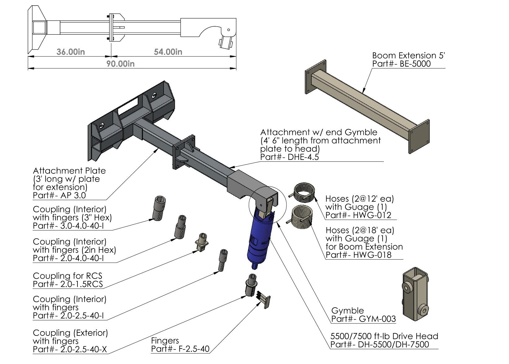
Figure 23

Figure 24
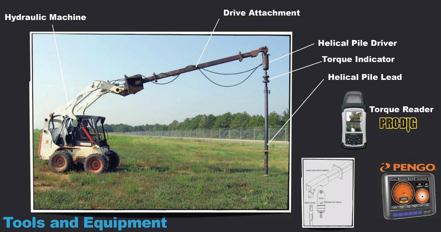
2�2�1 Equipment
The components of helical pile installation equipment consist of:
• Hydraulic Machine: Many different types and sizes of installation machines can be used for helical pile installation including backhoes, excavators, skid steers and truck-mounted drill rigs. The only requirement here is that the hydraulic machine needs to be matched with the size of the torque motor, which generally has a
minimum hydraulic flow rate and cannot be run with a small hydraulic power pack. Ideal advancement is defined as one helix pitch of vertical (downward) movement per one shaft revolution. The equipment should also be capable of maintaining proper pile alignment and position.
• Torque Motor: This is used to apply torsion or rotational force to the attached top of the helical pile. It is recommended that the torque motor used at the construction site should have at least 15 percent more torque rating than the minimum required installation torque for the project. The torque motor should also have clockwise and counterclockwise rotation capabilities and should be adjustable with respect to revolutions per minute during pile installation.
• Torque Indicator: Installation torque can be measured by different methods, including a torque indicator, which is more accurate compared to the other methods such as shear pins or in-line pressure gauges. The torque indicator can be an integral part of the installation equipment, and is an externally mounted device placed in line with the installation tooling. At Cantsink, we have different torque indicators with different torque capacities, used depending on the minimum required installation torque for the specific project. Proper measurement of the final installation torque is very important and is a crucial part of the installation process because it is used in the capacity-torque correlation to verify the design pile capacity in the field. For this reason, torque measurement equipment should be calibrated within one calendar year prior to the date of its use at the construction site. If there is any uncertainty at all about the accuracy of the torque measurement equipment, the torque indicator should be recalibrated before the project begins.
• Drive Tool: It is used to connect the helical pile to the torque motor and it should be straight and rigid. It is usually provided by the helical pile manufacturer to fit its product.
• Drive Pins: These are used to attach the helical pile to the drive tool. They are high-strength, smooth pins with an average diameter equal to the bolt size of the helical pile. It is very important that the pin diameter is the same as the bolt diameter used in the helical pile coupling. This will help prevent a bolt hole failure or rupture during pile installation, prior to achieving the minimum require installation torque.
2�2�2 Installation Techniques
Typically, the installation of a helical pile consists of rotating the pile shaft into the ground to advance the pile to the required minimum depth as recommended by the design engineer. The shape of the helix facilitates the installation of the pile by the rotation of the central shaft, with the pile ideally advancing into the soil at a rate of about one helix pitch for each full revolution.
The general procedure and steps for helical pile installation are summarized as follows:
- Attach the leading section to the drive tool with drive pins as required. - Center the helical pile at the location as marked on the engineering plan. - Push the helical pile downward until the bottom helix makes contact with the ground surface at the marked location. - Make sure the lead section is aligned and positioned at the desired location. Check plumbness with the help of a spotter. In the case of inclined piles, they can be initially positioned perpendicularly to the ground surface to assist in initial advancement into the soil before the required installation inclination is established. - Start rotating the helical pile into the ground (downward force). - Continue installation while checking plumbness as needed. - Make sure to record depth and torque at selected intervals. At Cantsink, our digital torque indicators provide installation log data (depth and torque) throughout the installation process.
- Once the installation of the lead section is complete (lead section is almost completely embedded into the ground), stop at the ground surface and make sure the spotter (helper) can see the drive pins clearly. - Take the drive pins out. Pull up the drive tool. Add an extension by connecting it to the lead section via the coupling. As each extension section is added, the connection bolts are typically snug-tightened, which indicates that the nuts and bolts are well seated. - Continue installation with added extension sections as required to achieve the minimum required torque and depth. The helical pile sections should be screwed and advanced into the soil in a smooth, continuous manner at an approximate rotation rate of 5 to 25 rpm. Keep checking plumbness as needed and keep recording depth and torque readings. - Once the minimum specified depth and torque are achieved, halt the installation. Take out the drive pins and pull up the drive tool. It is extremely important to record the final pile depth and installation torque. The final termination torque is used to verify the designed pile capacity based on the empirical capacity-torque correlation. - Cut the pile shaft to the final required elevation. - Mount the pile cap.
2�2�3 Installation Torque Measurements
During the installation of helical piles, the torque must be measured and recorded throughout the installation process. If the torque device doesn’t have the capability to provide installation log data, then the torque must be measured and recorded at some selected interval. Torque is an indicator of soil strength and therefore a good indicator of the pile capacity. Normally, the capacity torque relationship is used to predict and verify pile capacity in the field. It is the final termination torque (final reading torque at the end of installation) that is used in the capacity-torque correlation to verify pile capacity. Cantsink uses the final reading torque as the final installation (termination) torque to be used with the capacity-torque correlation.
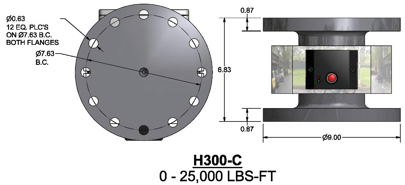
Figure 25
2�2�4 Installation Records
Installation records shall include, but are not limited to:
A. Date of installation B. Installation equipment type and operator name C. Plan location of helical pile D. Pile reveal E. As-built helical pile type and configuration (number of helices, shaft O.D) F. Total length of installed pile G. As-built installation angle of pile H. Torque measurements at the end of each lead and extension I. Final installation (termination) torque J. Comments pertaining to interruptions, obstructions, or other relevant information
Figure 26