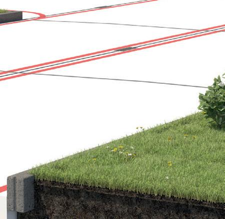
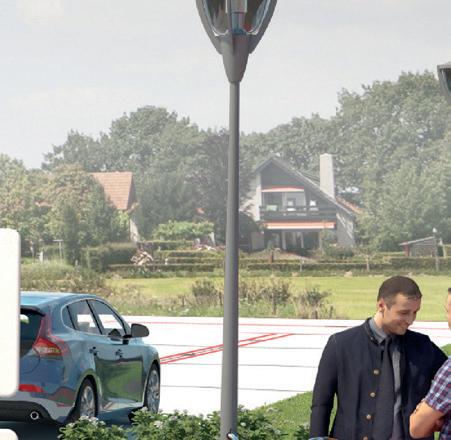
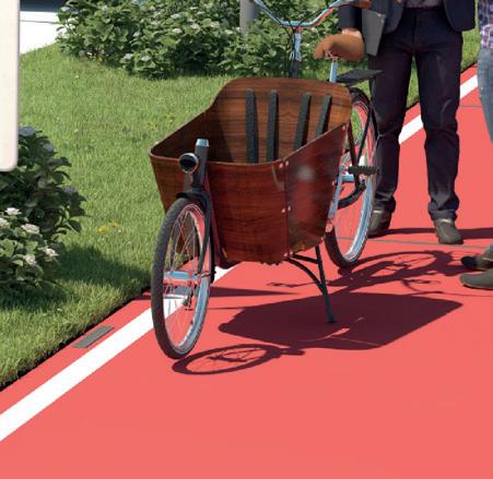
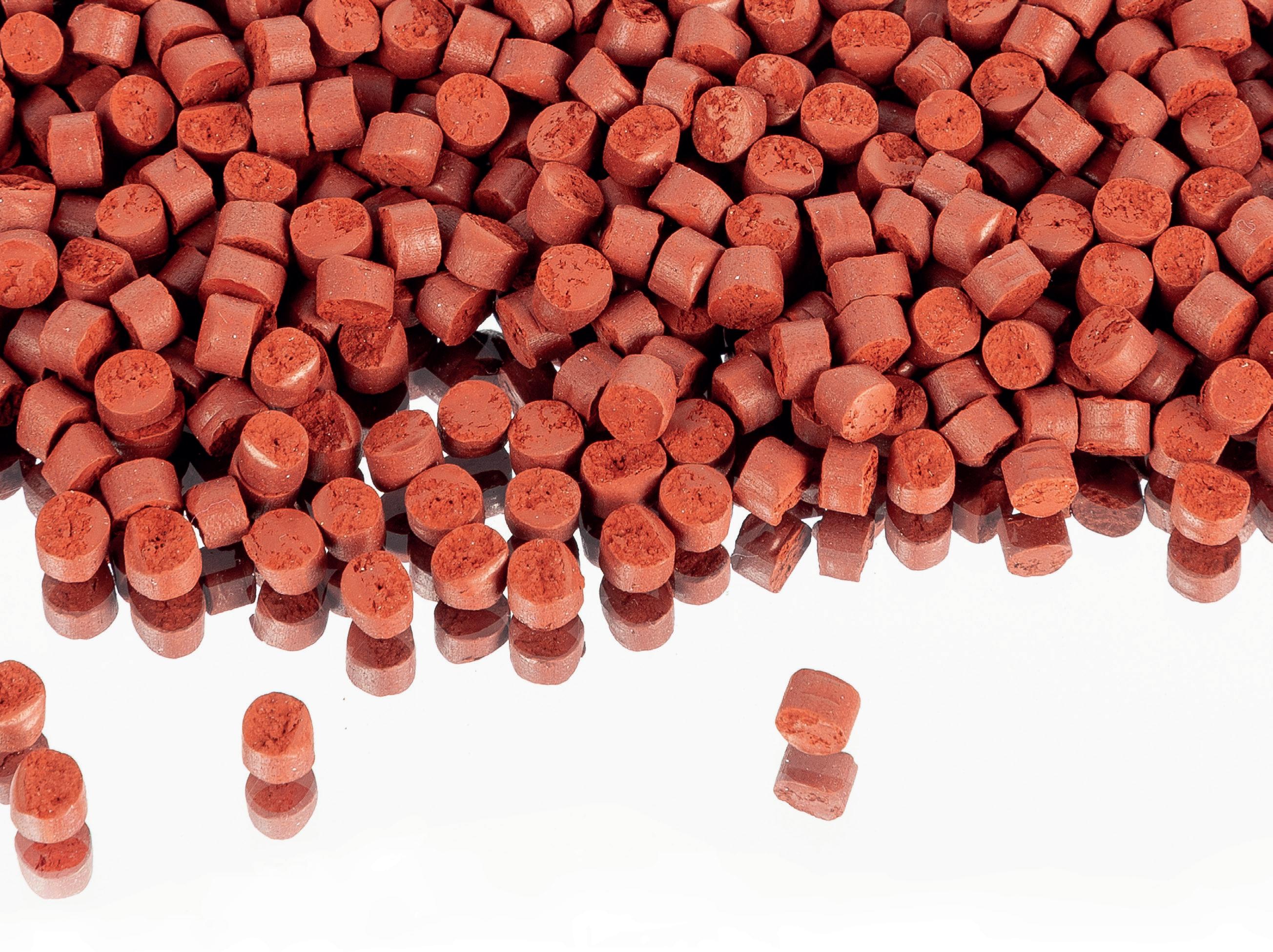
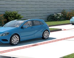
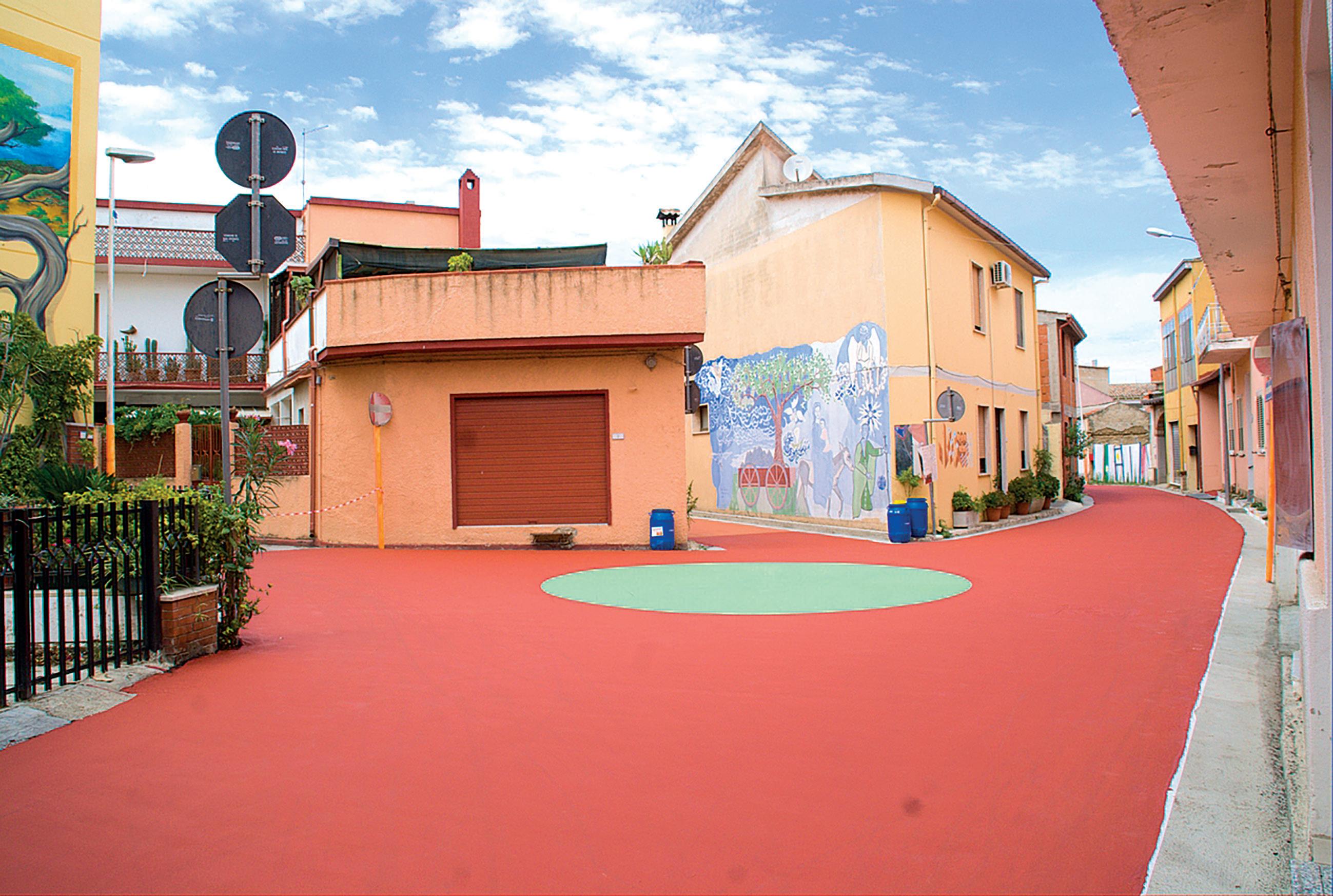
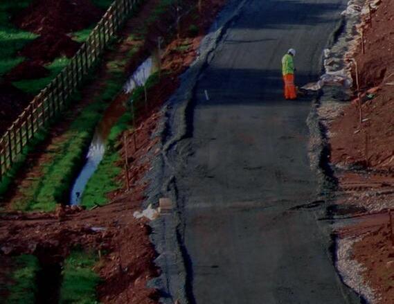
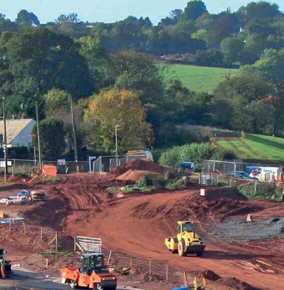
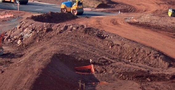
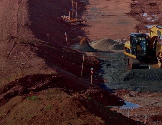
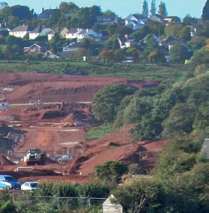
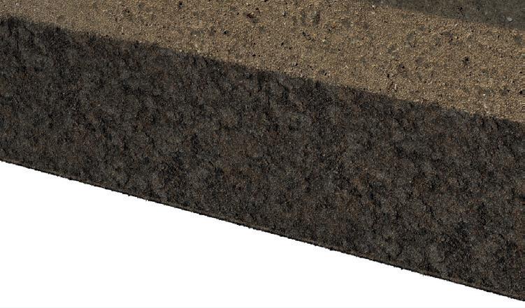
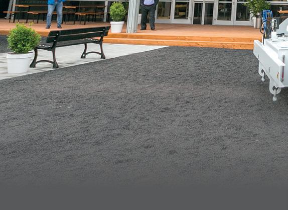
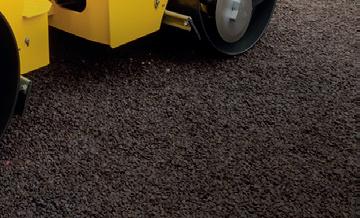
Applications of coloured asphalt pavements may contribute significantly to reduce the urban temperature and to mitigate the urban heat, improving microclimatic and environmental conditions.
EDITOR: David Arminas
CONTRIBUTING EDITORS:
MIke Woof, Geoff Hadwick
SUB-EDITOR: EKH Services
PRODUCTION MANAGER: Nick Bond
OFFICE MANAGER: Kelly Thompson
DESIGNERS:
Simon Ward, Andy Taylder, Stephen Poulton
CIRCULATION & DATABASE MANAGER: Charmaine Douglas
WEB ADMINISTRATORS: Sarah Biswell, Tatyana Mechkarova
INTERNET, IT AND DATA SERVICES DIRECTOR: James Howard
MANAGING DIRECTOR: Andrew Barriball
PUBLISHING DIRECTOR: Geoff Hadwick
CEO: Roger Adshead
ADDRESS:
Route One Publishing Limited, Waterbridge Court, 50 Spital Street, Dartford, Kent DA1 2DT, UK Tel: +44 1322 612055 Fax: +44 1322 788 063
Head of Construction Sales: Graeme McQueen Tel: +44 1322 612069
Email: gmcqueen@ropl.com
Classi ed Ads / UK / North America: Yvonne Tindall Tel: +44 1622 844027
Email: ytindall@ropl.com
Italy:
Fulvio Bon glietti Tel: +39 339 1010833
Email: bon glietti@tiscali.it
Asia / Australasia: Roger Adshead Tel: +44 7768 178163
Email: radshead@ropl.com
Published by:
2397-1088
ISSN 2397-1096
4: MEASURING MATURITY
Transtec explains the facts behind concrete maturity
6: FAULT DETECTION
A US state looks for surface cracks before it’s too late
11: COLOURED PAVEMENT
Iterchimica lowers the temperature in an Italian town
15: ULTRA-THIN HOT-MIX ASPHALT
Rethink how to restore old pavement
THE ROAD TO A BETTER ENVIRONMENT
Environmental concerns are increasingly close to the centre of many political, social and economic discussions across the globe. From air pollution in Chinese cities and oil-spill fears o Canada’s Paci c coast to plastic contamination of the high seas and the resulting poisoning of global sh stocks, the environment is getting a lot of media attention.
In August last year a 15-year-old Swedish school girl and environmental activist, Greta unberg, began spending her school days outside the Swedish parliament to call for stronger action on global warming. Part of her messaging has been that the 1.5°C commitment by governments as part of the Paris Agreement is insu cient. Greenhouse gas emissions need to start declining steeply no later than next year.
At this year’s conference of the European Economic and Social Committee, she said that the European Union must reduce its CO2 emissions by 80% by 2030, double the 40% goal set in Paris. unberg was recently featured on the cover of the US news magazine Time, calling her a “nextgeneration leader”.
But there are many similarly committed leaders who work tirelessly behind the scenes to ensure that the activities of their businesses and sectors in general cause less disruption to the environment. And many of these leaders are in the asphalt and concretepaving sector, as this issue of Road Surface Technology highlights. Indeed, the front cover and our article on more environmentally friendly roads show just how forward thinking is the sector.
Iterchimica, in Italy, explains how the use of coloured pavements can help lower air temperature in residential areas. e US state of Alaska is looking for surface-layer defects before they become premature failures needing extensive repairs – and which would increase the carbon footprint, and cost, of the state’s maintenance work. Also in the US, a major survey by the National Asphalt Pavement Association shows a dramatic increase in the use of recycled asphalt pavement – big savings on asphalt binders, energy used for paving and material sent to land ll.
Aecom in Australia has been showing that rehabilitating pavement is technically more complicated than many engineers believe, but getting it right will mean longer-lasting surfaces. Also, as engineering consultancy Transtec shows us, there are now better ways to measure concrete maturity than destructive testing methods. South Korean paving specialist Hansoo Natech has been using ultra-thin hot-mix asphalt paving to do away completely with the need for milling old pavement surfaces.
But the sector is also at something of a crossroads. Society knows that transportation systems must change to improve the environment, which means big changes for road design, construction, operation and maintenance. But few people know exactly what will be needed by 2040 or 2030 - or even 2025. Still, our sector’s innovation continues apace as witnessed within the covers of this year’s Road Surface Technology
David Arminas, EDITOR darminas@ropl.com
20: PAVEMENT REHABILITATION
Advice on in-situ recycling and the re-use of pavement layers
25: PLASTIC ROADS
Keep control of your company’s new technology
26: NAPA SURVEY
e National Asphalt Pavement Association’s annual review of recycled materials and warm-mix asphalt
30: PAVEMENT ASSESSMENT
An Intelligent Pavement Assessment Vehicle (iPAVe) travels South Africa
33: PAVING ROUND-UP
Latest advances in paving machines over the past year
37: COMPACTION ROUND-UP
What’s new in the world of compaction equipment
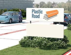
Front cover picture, courtesy of PlasticRoad
What
is the concrete maturity method and how is maturity measured?
Pavement engineering specialist Transtec explains
The maturity method is an American Society for Testing and Materials-standardised, nondestructive testing method for estimating concrete strength that provides real-time results. Typically, cylinders and beams are required to be cast and broken for quality control and 28-day acceptance. It is common practice to simply cast and break additional samples, sometimes referred to as companion samples, for estimating early-age strength of in-place concrete for purposes such as early form removal, post-tensioning of elevated slabs, and fast-track pavement construction and repair.
However, the strength gain of these cylinders may not re ect the strength gain of the in-place concrete. For example, when placing concrete in ideal or hotweather conditions, strength gain will likely occur faster for in-place concrete than for companion cylinders or beams, simply because of the di erence in size and heat generation during hydration. For the same reason in cold weather, it may be that in-place concrete gains strength slower than companion cylinders, particularly if companion cylinders are cured at warmer temperatures.
Maturity bridges the gap between what is tested for in companion samples and what eld conditions are assumed. Maturity uses sensor technology to provide real-time updates of in-place temperature and age.
is allows users to estimate strength based on a maturity curve developed by breaking cylinders or beams.
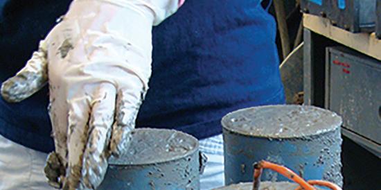
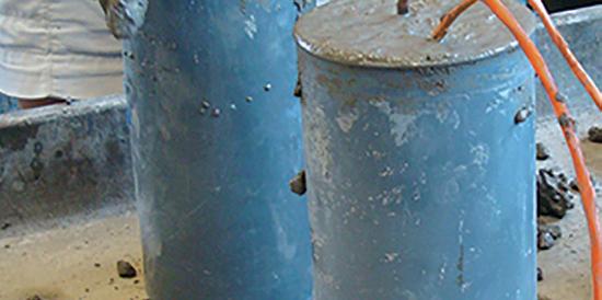
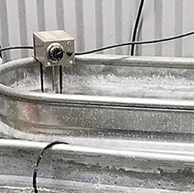
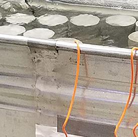
e relationship between concrete maturity and strength can be graphically represented using a maturity curve. To develop a maturity curve with cylinders according to ASTM C 1074, concrete cylinders are cast from a trial mix. A sensor is embedded at the centres of two cylinders. e cylinders are all cured in the same environment, then at 24 hours, 72 hours, seven days, 14 days and 28 days (unless alternate intervals are otherwise speci ed by an engineer), a minimum of two cylinders are broken.
e compressive strengths are averaged and recorded. At the same times the cylinders are broken, maturity is calculated using the sensors’ temperature history data. e resulting data is then plotted on a graph with maturity on the x-axis and strength on the y-axis, and a curve is t to the data. is resulting correlation curve can be used in future eld applications. Users can simply compare the measured maturity value of the concrete to the curve and estimate the strength.
Each concrete-mix design has its own unique maturity curve. Changes to the mix, such as a change in aggregate type or content, water to cement ratio, cement type, or supplementary cementitious material source, can in uence the relationship between maturity and strength. To successfully
implement the maturity method in the eld, the concrete delivered must be consistent with the concrete used during testing to create the maturity curve.
Because maturity curves are unique, it is important to ensure that the proper curve is being used to estimate strength. ASTM C 1074 includes a few options for this validation process including cast-in-place cylinders, penetration resistance test and pullout test. But the most commonly used option is early-age tests of eld-moulded cylinders instrumented with maturity sensors.
e steps to validate the maturity curve:
1. When pouring concrete on site, cast three cylinders using the same concrete as being placed. Place a temperature sensor in one of the cylinders and be sure all three cure together in the same environment.
2. When you are ready to validate, break the two cylinders without sensors and nd their average compressive strength.
3. Read the maturity index from the embedded sensor and use the maturity curve to nd the estimated strength.
If the measured compressive strength and the estimated strength agree within 10%, then the maturity curve is validated. If the strengths di er by more than 10%, then this indicates enough change in the mix that a new curve should be generated to better represent the mix.
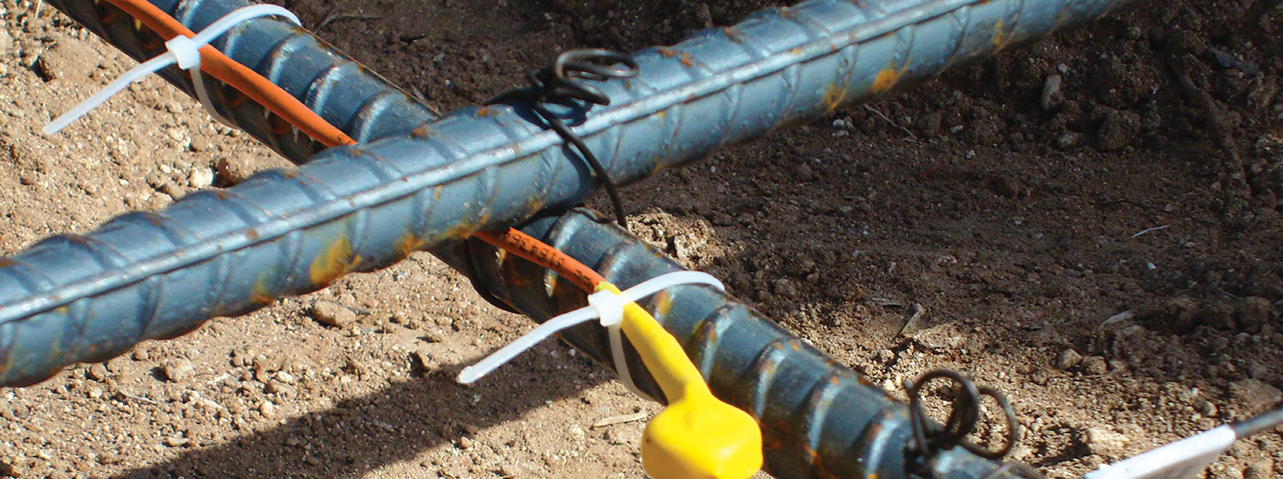
Sensors on rebar just before a concrete pour
Validation of the maturity curve should be performed periodically and at speci c intervals – weekly, monthly, seasonally –depending on di erent job speci cations. ough validation is not required before every use of the maturity curve, it should be performed regularly as it is crucial to performing this test method properly.
VALIDATION
Validation is part of the ASTM-standardised maturity-test method and is recommended periodically as best practice to achieve the highest accuracy possible. Since each curve is particular to the concrete mix for which it was designed, if any mix condition or constituent has changed signi cantly, the correlation between the maturity and
TESTING TIME IN TEXAS
O. Trevino Construction, based in the US state of Texas, has been using COMMAND Center since 2004, employing it on hundreds of full-depth pavement repair projects of all different sizes throughout the Dallas-Fort Worth area. Scott Riegler, a project engineer with O. Trevino, says that COMMAND Center and maturity monitoring has helped build the company’s reputation with the Texas Department of Transportation.
“We went out to a project way back then and the lab supervisor was sceptical that maturity would work,” said Riegler. “I told him that I would take a reading with the maturity meter, you break the beam, and we’ll share the results. We were within three or four pounds [<2kg] of each other.”
Cylinders and beams are required to be cast and broken for quality control
strength changes as well; the estimations for strength based on the maturity curve may not re ect the true strength of the concrete. is can result in liability issues or structural issues. If the concrete is mistakenly assumed to have reached su cient strength when it has not, it may fail when under load.
Validation can also work as quality control. If the measured strength and estimated strength di er by more than 10%, it may be a result of inconsistency between the concrete delivered to the jobsite and the concrete tested in the laboratory. In this case, corrective action can be taken before extensive rework would be necessary.
Systems like COMMAND Center greatly ease the process of validation by automatically creating maturity curves
Typically, in full-depth pavement repair projects, teams will break beams or cylinders to test concrete strength for opening to traf c. However, beams are labourintensive to make and break. If someone doesn’t make a beam correctly, the team could be stuck waiting on the lab for hours. Beams are very heavy and can be dangerous to move, especially in inclement weather.
COMMAND Center employs small, self-powered sensors placed in fresh concrete that automatically measure temperature data at predetermined intervals and store data internally. The sensors transmit data to a compatible device running the free, powerful COMMAND Center software. COMMAND Center software uses
Maturity uses sensor technology to provide real-time updates of in-place temperature and age
based on a user’s break data. A ordable smart sensors are embedded in the concrete and continuously collect temperature and maturity data. Users can retrieve the data wirelessly to their iOS device or using a handheld device connected directly to the sensors. e data can then be viewed and analysed on COMMAND Center’s free and powerful so ware. Users can see a complete temperature and maturity history of the concrete and create maturity curves.
Estimating in-place concrete strength using the maturity method is the easiest and most e cient way of nding real-time strength. To ensure that this method is being executed properly and accurate results are being obtained, it is recommended that the maturity curve be validated before use.
the time and temperature data and applies the Nurse-Saul or Arrhenius formula to easily and automatically calculate maturity - a proven scienti c method that estimates when the concrete has achieved the desired strength.
Using COMMAND Center and the maturity method can reduce the number of beams a team must make and break. They will know sooner when their concrete has reached suf cient strength, allowing them to open roads to traf c earlier and get workers out of dangerous work zones more quickly.
COMMAND Center Sensors should be placed at critical locations in the concrete element being monitored. The number of sensors used depends on the
job size. O. Trevino tasks their superintendent with monitoring the sensors and after about three and a half hours will begin to check the data every 10-20 minutes.
COMMAND Center Sensors store readings at pre-de ned xed intervals to t the customer’s speci c needs for concrete monitoring.
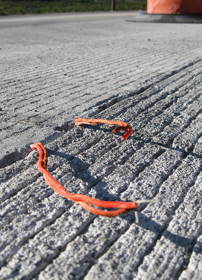
“We like the two-minute intervals because we want to open the road as soon as we can,” said Riegler. “You just put the sensors in the concrete - they are already calibrated so you don’t have to do anything. The orange leads make it easier not to accidently saw cut them. COMMAND Center shaves at least 30 minutes off every beam break, so we’re saving about four and a half hours each day.”
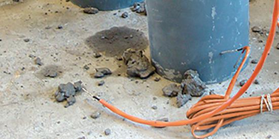
Bright colour leads make locating sensors easy a er concrete pour is completed
The
Alaska Department of Transportation is committed to looking for surface layer defects before they become premature failures, writes Rob Sommerfeldt*
For the past 40 years, state departments of transportation across the US have been basing quality measurement testing for road-paving projects on random sampling of materials. For example, one lot of asphalt is 5,000 US tons (4,536 tonnes), which is divided up into 10 sub-lots each of 500 US tons (453 tonnes). Quality assurance (QA) personnel use a random number generator to select where each sublot would be sampled while placing the mix on the grade to check for oil and the gradation of the aggregate. Next, they randomly select a separate location to take a core in the paving mat and at any longitudinal joints between two lanes.
QA personnel then use statistical methods on these random samples to generate information on the theoretical distribution of road-paving material properties. From this can be calculated the average density of material placed.
This method does not sit well with Rich Giessel, Alaska’s state-wide quality assurance engineer. Giessel maintains that there are numerous problems with random testing. It is not suitable for heterogeneous materials and will not find defects on paving projects.
The method is based on two false premises. The first is the assumption that soils and other road construction materials will fall on a Gaussian distribution – a normal curve – which, he says, they almost never do. The second false assumption is that highway authorities should care most about the average density values from random testing.
“Random sampling is a really good way to get the average,” explains Giessel. “But when you are doing one test that represents one square foot every 500 tons (453 tonnes) there are thousands or hundreds of thousands of square feet we have not even looked at. Also, the average spot is never what gives us a problem or a failure on the road – it is the weak spots. Random testing never finds your low spots and your weak spots so there is little to no probability of locating pot-holesize defects.”
Unlike traditional random sampling, continuous testing uses multiple inputs to “look for” failure zones. Continuous testing has a high probability of detecting defects before they lead to premature failures.
EXIT THE STATUS QUO
The system he favours uses three components: intelligent compaction (IC), a paver-mounted infrared (IR) thermal profiler/scanner and a ground-penetrating radar (GPR) rolling density meter. With IC, compaction rollers are equipped with accelerometers and computers that measure surface density and rebound, also known as relative stiffness. This is related to the materials’ resilient modulus (MR), a measure of material stiffness that is used for designing traffic loads. IC offers geo-located data, continuous full-coverage, real-time compaction of the entire hot-mix asphalt mat, along with temperature mapping at the time of the roller pass.
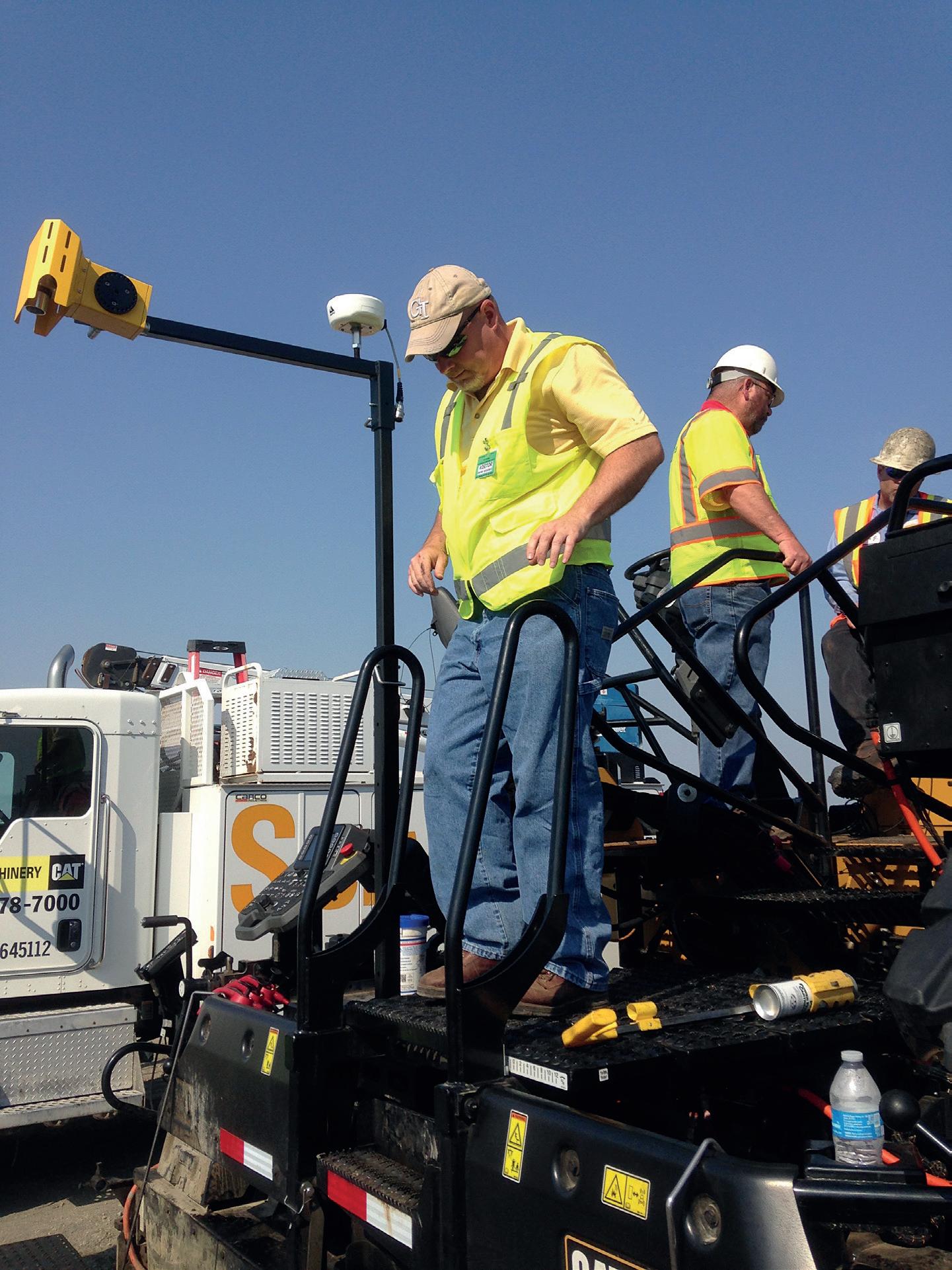
Next is an IR thermal profiler mounted on the paver, which provides a continual map of the temperature of the asphalt as it is laid down right behind the paver. The
ABOVE: PaveScan “sees” defects before they become real problems for the road surface
thermal IR scanner provides geo-located data and a complete map of asphalt mat surface temperature that is viewable in real time. It also calculates the degree of thermal segregation every 150 feet (45m), providing a permanent temperature record.
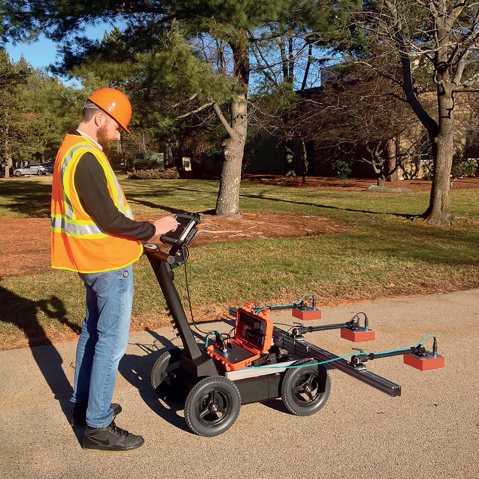
The last element in the system is the ground-penetrating radar (GPR) asphaltdensity meter. This evaluates void content while rolling along, taking a measurement every square foot of the pavement after compaction. This is a huge advance over the prior random sampling method. Instead of 50100 random tests, the GPR method provides 2.5 million tests – one on every square foot (929cm²). This enables quality assurance personnel to finally find defects. Since the method provides geo-located data, they can go back and fix issues before premature failure such as road raveling, cracking and deterioration along joints.
The ability to measure voids is a major benefit, since inadequately compacted asphalt deteriorates much more quickly than properly
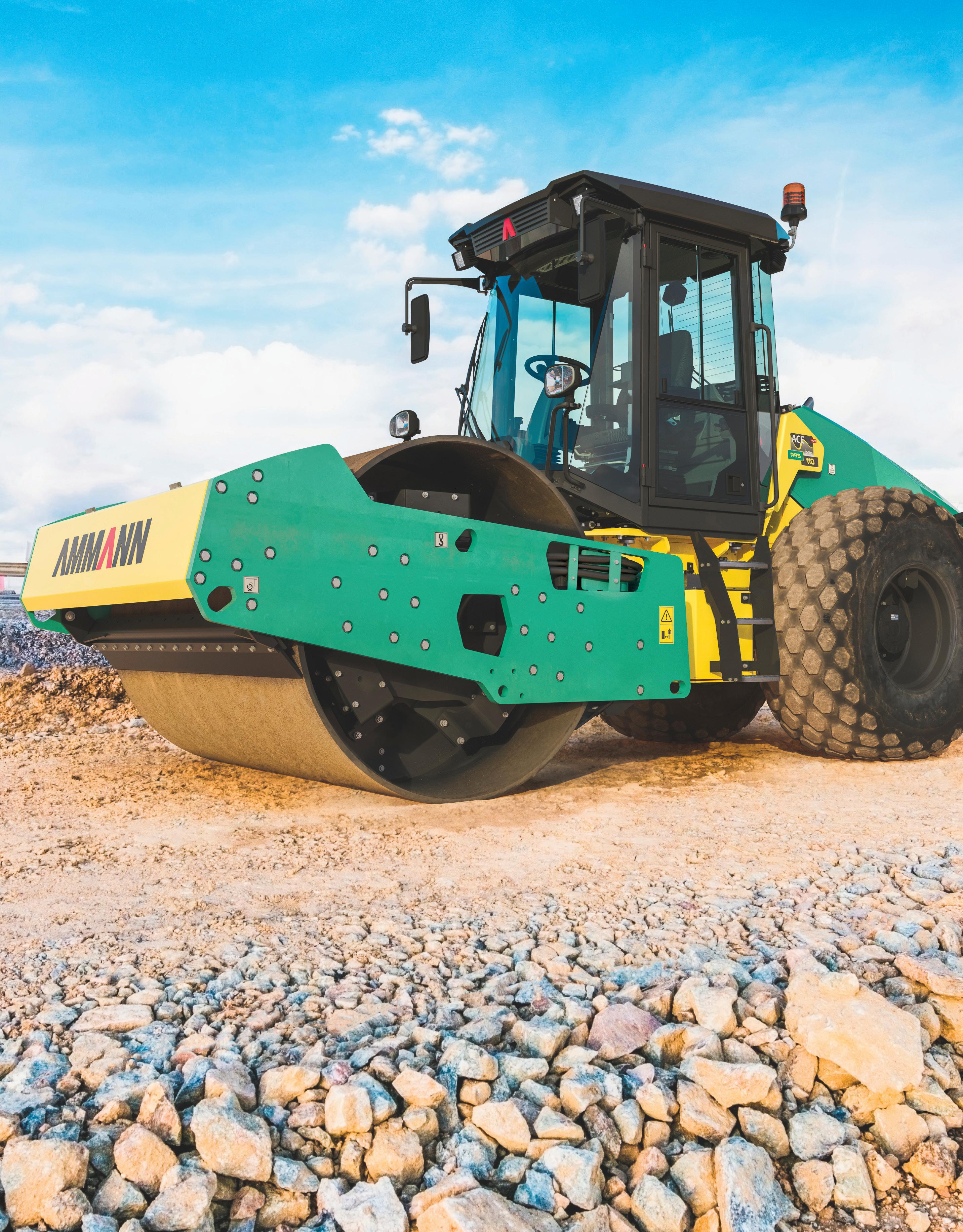
AMMANN ARS SOIL COMPACTORS
PRODUCTIVE. SUSTAINABLE. COST-EFFECTIVE.
Ammann ARS Soil Compactors utilise advanced technology that meets the latest emissions standards, reduces fuel usage and gives operators valuable data that eliminates unnecessary passes.
That’s just the beginning of the advantages these machines offer.
• The compactors are extremely manoeuvrable and stable thanks to the no-rear-axle structure.
• Multiple vibration frequencies and centrifugal forces enable productivity on a wide range of materials and compaction thicknesses.
• The new ECOdrop initiative and new technologies improve efficiency and reduce fuel consumption and the amount of required fluids.
compacted material. Asphalt with too many air voids ages at a more rapid rate due to oxidation of the binder. Over-compaction may cause crushing of aggregate or low air void content, leading to rutting or flushing.
In either case, the asphalt is subject to early failure and road lifetime is less than with asphalt that contains the optimal air void content.
This approach is in line with research Giessel had been following as part of the US Federal Highway Administration’s (FHA) Strategic Highway Research Program 2 (SHRP 2), specifically the Renewal Project RO6C (Using Both Infrared and High-Speed Ground-Penetrating Radar for Uniformity Measurements on New Hot-Mix Asphalt Layers).
As part of SHRP 2, the Texas Transportation Institute developed a way of using IR and radio-wave technologies to improve the assessment of asphalt mixture and compaction quality. The institute later worked with GSSI - Geophysical Survey Systems Incorporated - to package the radio wave components into the PaveScan RDM asphalt-density assessment tool, a streamlined and operator-friendly device that provides real-time profiling of mixture uniformity.
After this first phase, the US states of Maine, Nebraska and Minnesota continued the research under the federally funded SHRP 2 project. The Alaska Department of Transportation (DoT) participated in two demonstration projects with technology company MOBA Mobile Automation, first with the PAVE-IR Bar and more recently using the PAVE-IR Scanner, a pavermounted thermal profiler.
PAVESCAN IN ACTION
Alaska DoT conducted demonstrations of the PAVE-IR technology in 2011 and began using intelligent compaction in 2013. While visiting an infrared showcase, Giessel saw a demonstration of GSSI’s PaveScan RDM and had the opportunity to see the tool in action.
Alaska roads can be very affected by freeze-thaw cycles. The capital city of Juneau is affected most, with about 50 freeze-thaw cycles per year, giving it extremely difficult conditions to maintain.
Giessel got the opportunity to use all three components together as part of the recently completed Glenn Highway: Hiland Road to Eklutna Pavement Preservation project - 15 miles (24km) of 4-lane expressway, requiring just over 50,000 tons (45,360 tonnes) of
asphalt. This was a 2-inch (50mm) mill-andfill project, where contractors milled out 1.75 inches (44.5mm) or 2 inches (50mm) and put back 2 inches (50mm) of material.
Beginning in 2016, Alaska DoT used the IC and PAVE-IR paver-mounted thermal scanner technologies as contractor pay factors as part of project acceptance. The PaveScan RDM asphalt-density assessment tool was used only as a technology demonstration. They obtained full coverage data, but did not connect the information to any pay factors.
Giessel is extremely pleased with the results of the project, noting some unexpected findings such as with the PaveScan RDM’s data concerning compaction at the road shoulder. The project called for milling out and leaving a paved shoulder with a rumble strip. QA engineers found that in some cases the asphalt was not stacked high enough above the paved shoulder to get really good compaction.
In the past, the QA engineers had rarely cored near the edge, so had not observed this area of low compaction. The random selection almost never got within a foot of the rumble strip. Now, the PaveScan RDM measures every couple of feet across the road and engineers are picking up on the shoulder compaction issue.
Another interesting finding observed during calibration is that PaveScan readings are much closer to the cores than the nuclear gauge, which had always been their standard
proxy for cores. The correlation coefficient (R2) for the nuclear gauge is only .82 (82% accurate), while the R2 with the PaveScan is .93-.95 (93-95% accurate), which really boosted their confidence in the data.
One other significant finding is the ability to use PaveScan to “see” defects they have never seen before. “We had never been able to see what was going on at those longitudinal joints before,” says Giessel.
“Instead of just running parallel down the highway, I turned the PaveScan 90 degrees and went across those joints perpendicularly. We could see as much as a 10% compaction dip right at the joint between the milled edge and the new hot mix where the hot and cold edges had not melted together well. That was data we had never been able to see before,” he says.
As the first state proposing to use the new system for acceptance, Alaska has received encouraging support from the Federal Highway Administration. The FHA also supports the idea of not having to fund another project prematurely because something was not done well. This technology and implementing this type of specification has the potential to save the state millions of dollars in annual maintenance.
*Rob Sommerfeldt is an application specialist for road and bridge sales, specialising in GPR with GSSI (Geophysical Surveying Services Incorporated).
RIGHT: Thermal profiling in Alaska with Paul Angerhofer, product manager at MOBA for the PAVE-IR Scanner
Local governments and urban residents have been asking for coloured pavement for purely aesthetic reasons
Iterchimica* worked with Italy’s University of Padua to examine the use of coloured pavement in urban areas to lower air temperature
Coloured pavements came into being in response to a demand from local governments and urban residents for improved aesthetics of streets. But, nowadays, coloured pavements provide a wide range of advantages, from improved surface durability to greater safety [1].
Colour is being introduced into road pavements for a number of reasons. It can improve safety for cyclists by better delineating cycling routes to keep bicyclists and pedestrians apart.[2]
Coloured pavement can delineate vehicle express lanes and bus routes from regular vehicle lanes. At intersections, different colours can guide vehicles, especially during heavy traffic, into correct lanes and improve the visibility of ramps, road shoulders, median strips and traffic islands.
More recently, in Italy and Japan, lightcoloured pavement has been used in tunnels to reduce the need for much brighter lighting and thereby lower energy costs for tunnel operators and owners [3] [4]. In some cases this has been between 30-40% [5].
Besides safety and economic benefits, the use of coloured pavements can be
considered an eco-friendly solution for urban streets by reducing the temperature of the pavements. Research has been carried out by Iterchimica and the University of Padua on the heat properties of coloured pavements. Tests were conducted on various materials and aggregates to assess the possibility of reducing the temperature through the use of coloured pavements.
VARIETY
OF PRODUCTS
Iterchimica products that were used in the study can be divided into four main groups:
• Oxides (both in pigment and powder form);
• Resins (both coloured and transparent, which can be mixed with oxide powder to produce coloured mixtures with resin binders and colourful aggregates);
• Mortars;
• Paints.
Oxides and transparent resins are used for coloured-mix production and the coloured resins, mortars and paints are used for surface applications. It should be noted that the mix of transparent resins and powder oxides can be used also for producing
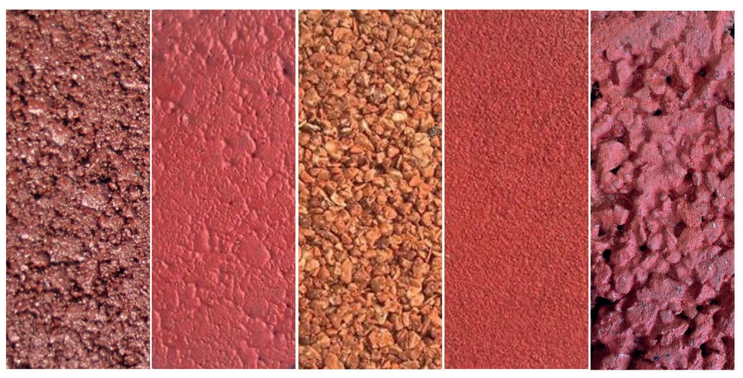
coloured mixtures. While resins and mortars almost cover the surface with a thin layer, suitable for dense-graded, closed-surface mixtures, by using the paints, the macro texture of the pavement’s surface can be maintained. In this respect, the difference between the mortars and coloured resins results in rougher finished mortar surfaces, providing more surface friction.
A series of roller-compacted densegraded asphalt mixtures was produced using different types of aggregates – limestone and yellow marble, for example – with different base colours. Four different mixtures with the same grading curves but different in the colouring type were produced:
• Mixtures containing colouring oxides and bitumen binder;
• Mixtures with transparent resin;
• Mixtures with bitumen binder and colouring resin on the surface;
• Mixtures with bitumen binder and coloured mortar on the surface.
The research plan included both basic mechanical and heat flow/emission properties of the coloured asphalt mixtures. The mechanical properties were investigated
in terms of tenacity and stability. Heat flow/ emission assessments were done in terms of maximum temperatures, emissivity, albedo and the Solar Reflectance Index (SRI).
Two different binders, a neat and SBS PmB, were used for the mixtures coloured with colouring oxides, investigating the probable influence of the type of bitumen binder on thermal properties. Mixtures without colouring oxides were considered as reference mixtures.
The test results showed that the addition of oxides enhances the mechanical properties. Results were recorded by means of Marshall Stability and Indirect Tensile Strength (ITS) tests.
COOL PAVEMENTS
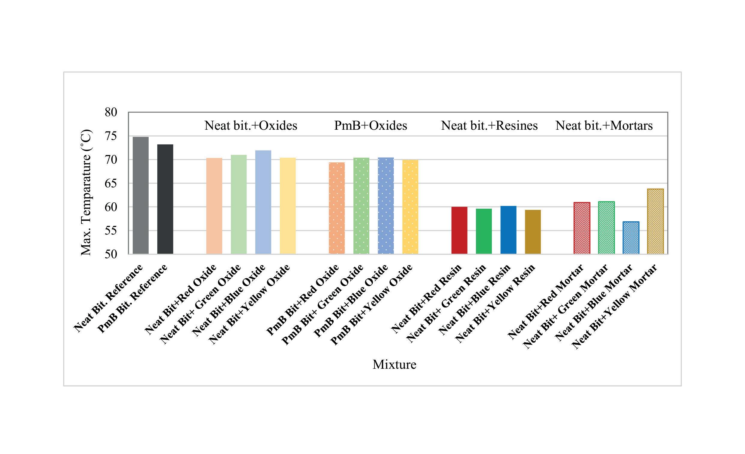
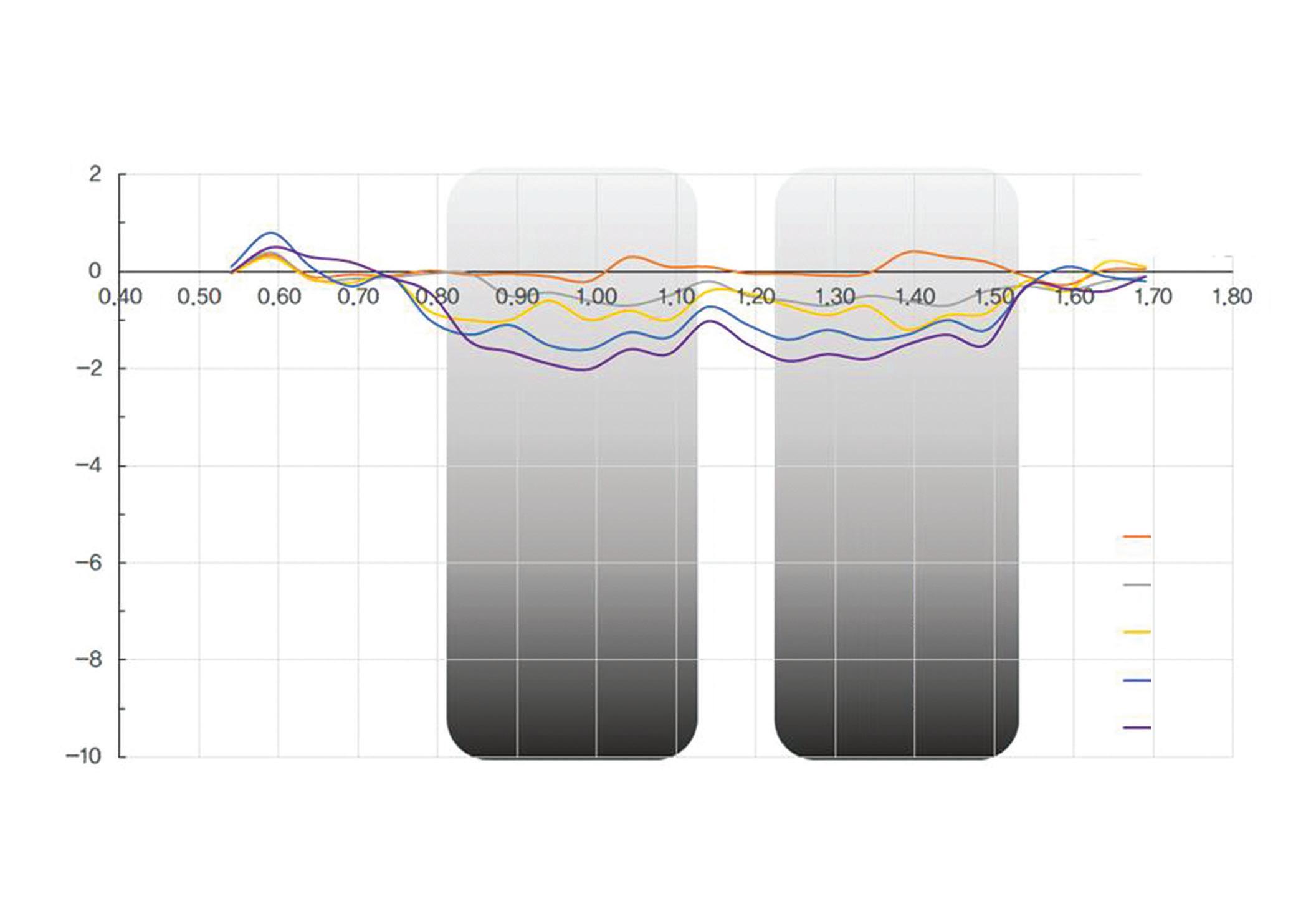
The maximum temperature of the asphalt mixtures was determined under both internal synthetic heating and outdoor conditions. Test results showed that the temperature of the coloured asphalt mixture slabs was significantly lower than the reference slabs that had no oxides or surface colour. Thanks to the thick layer of colour provided by resins and mortars, the temperatures are much lower than the same colour asphalt mixtures containing oxides.
Research was then dedicated to thermal indices comparing the thermal properties of coloured pavements. The emissivity, albedo and Solar Reflectance Index (SRI) of the slabs were calculated. Emissivity was calculated by comparing the temperatures measured on the slabs to a material with known emissivity, heated with the same amount of heat. All the pavements showed almost the same results. However, the emissivity of resins and mortar slabs was marginally higher.
The albedo of the coloured pavements were measured. Albedo can be defined as the ratio between the reflected solar radiation and
the solar radiation on its surface. Hence, the higher the albedo, the cooler the pavement is. The calculations showed that colour has a significant effect on the albedo.
The albedo of the coloured pavements with resins was almost three times that for the uncoloured reference asphalt mixtures. Coloured pavements with mortars were almost double compared to the reference pavement. These results showed the ability of coloured pavements to reduce the temperature by higher reflectance.
In addition to albedo, the Solar Reflectance Index (SRI) of the coloured pavements was determined according to ASTM E 1980-11. The SRI value range is between 0.00 to 1 (0% to 100%), where 0.00 represents a nonreflecting surface and one a fully reflecting surface.
The SRI values, in line with albedo, showed the effectiveness of the coloured pavement in reducing the temperature of the pavement. While the SRI value of the reference pavements (not coloured, almost black
pavements) were zero (for the PmB mixture slightly more), the SRI values of the coloured pavements were significantly more. In this respect, the average SRI of the oxide-coloured pavements was 0.24, for mortar coloured pavement 0.72 and for resin-coloured pavements 0.84.
All the test results proved the possibility of reducing air temperature with coloured pavements. This solution becomes more important given concern over global climate change. The variety of the colouring products provides a wide range of choice for any location and purpose, from parking lots to airport aprons, from cycling paths to bus express lanes.
*Loretta Venturini is a technical director and Shahin Eskandarsefat is a scientific technical development expert, both with Iterchimica
[1] L. Venturini & L. Sangalli. Color it safe. Road Surface Technology, pp. 32-33, Issue 4, 2018.
[2] G. Koorey & E. Mangundu. Effects on motor vehicle behavior of color and width of bicycle facilities at signalised intersections. 89th Transportation Research Record (TRB) annual meeting, Washinton DC, U.S.A., 2010.
[3] T. Inoue. Colored pavements. Technology Research Center, Nippon Hodo Co., Ltd, pp. 33-36.
[4] E. Bocci & M. Bocci. Clear asphalt concrete for energy saving in road tunnels. Proceedings of the 12th Int. Conf. on Asphalt Pavements (ISAP), Vol 2: pp. 1817-1825, 2014.
[5] M. St-Jacques. & Y. Brosseaud. Coloured Bituminous Wearing Courses in France, Overview of Uses, 10th International Conference on Asphalt Pavements, vol. 3, pp. 233-242, 2006.
Fig. 1: Surface appearance of asphalt mixtures with different types of colouring materials (always red)
Fig. 2: Maximum temperature of different types of coloured pavements
LISTEN TO OUR CUSTOMERS
For 40 years and counting, ADM has been committed to producing quality, high-production asphalt plants. On top of that, we take great pride in delivering an unmatched level of service before, during and after the sale. At the end of the day, our plants speak for themselves. But we certainly appreciate that our customers have so many good things to say. They’re the ones we listen to, and we think you should, too.
“I had an ADM plant in my former business and had tremendous success with it. I really saw no reason to look elsewhere.”
- Steve Bevilacqua President/Owner Bevilacqua Asphalt
ULTRA-EFFICIENT ULTRA-THIN
Rethink your options when it comes to restoring old pavement, says South Korean paving specialist Hansoo Natech*
Ultra-thin hot-mix asphalt paving - sometimes called re-cover asphalt - can extend the life of existing pavement and reduce traffic noise. The method calls for a 2cm-thick application of ultra-thin hot-mix asphalt and the transportation and compaction of an asphalt mixture based on a CSM modifier with maximum aggregate size of 5mm. The mix design of this method was performed according to the following tests: MMLS3 (third-scale Model Mobile Loading Simulator Test), Hamburg Wheel-Tracking and Acceleration Pavement Test.
Importantly, the hot-mix is applied on the existing pavement surface without any milling. Cationic latex-modified emulsified asphalt is used as a tack-coat material to improve the adhesion between old pavement and the ultra-thin layer of
asphalt. The construction method and equipment are the same as that used for general asphalt pavement. Compaction equipment is generally done using tyre and tandem rollers.
CSM MODIFIER
The performance test of the CSM modifier for noise reduction and preventive maintenance showed the quality index of PG 82-22. Test results of the CSM modifier are given in tables 1 and 2. The fine fibres used in the preparation of the CSM modifier were cationic-treated with an average diameter of 4-6 μm and a tensile strength of 80,000 psi (5,515 bar) or more. The fibres physically exhibit the effect of increasing the tensile strength of the asphalt mixture by random distribution of fibres and network formation in the asphalt mixture. Also, it disperses compressive
stress from the upper part to reduce plastic deformation and disperses the tensile stress coming from the lower part to improve reflection crack resistance.
TEST METHODS
MMLS3: The specimens for the small package acceleration test consisted of two layers of 40cm x 40cm x 5cm specimens made using the wheel-tracking compaction tester. After 5cm of intermediate layer specimens were prepared, the interlayer surface was cured after one curing period. In the case of general HMA specimens, a mixture of 5cm in the case of the recycled asphalt mixture was used, 3cm of general HMA was installed and 2cm of wooden plate was placed on top of it.
Then, the wooden plate was removed and a 2cm amount of recycled asphalt mixture was laid, with compaction then
Table 1 Properties of CSM
Table 2 Properties of CSM
carried out. The roller temperature of the wheel-tracking compaction tester was maintained at 175°C. The compaction load was maintained at the centre of the mould and the centre of the compaction plate at a load of about 1,000kg. The number of compaction times was 30 reciprocations to prepare a slab specimen.
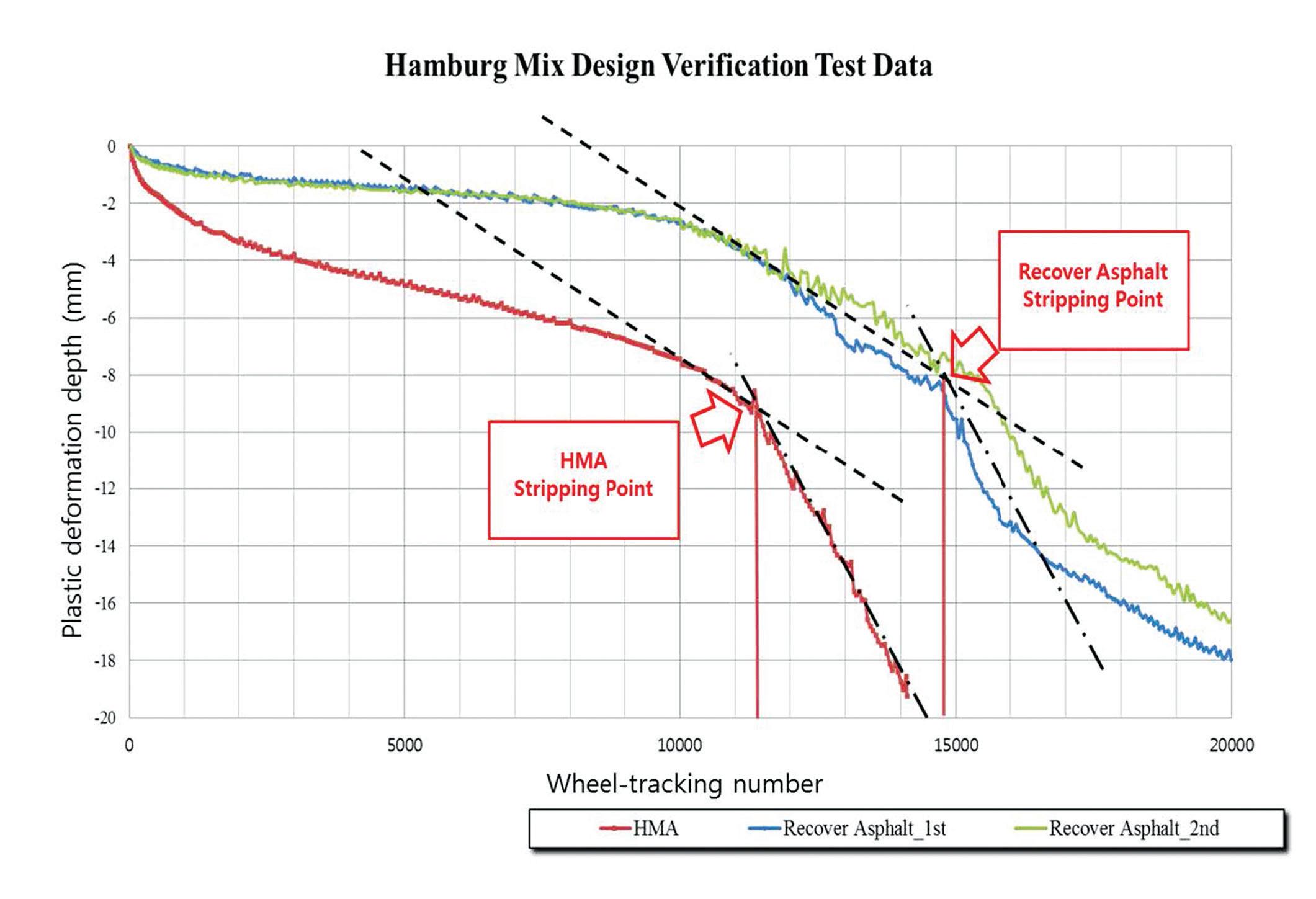
Hamburg wheel-tracking: The test was conducted according to the test method specified in AASHTO T 324: Hamburg Wheel-Track Testing of Compacted HotMix Asphalt (HMA). The specimen was immersed in water at 50OC and a wheel
load of 705N (±4.5N) was repeatedly applied. In the test standard, the US TEXAS Road Traffic Bureau standard should be less than 20mm after 10,000 landings and 20,000 wheel loadings.
APT: This test evaluates the repair method of paving materials in a short time by simulating actual road conditions. It investigates the pavement material structure by controlled vehicle load and environmental conditions.
TEST RESULTS
For the MMLS3 test, the following figure
Plastic Deformation in MMLS3 Test
is a graph showing plastic deformation according to the number of wheel-load passes over time. Plastic deformation for the general asphalt mixture was 5.87mm after 300,000 wheel loads. Maximum plastic deformation for the re-cover asphalt mixture was 4.613mm.
As a result of the Hamburg wheeltracking test of the mixture of general asphalt mixture (WC2 dense asphalt) and recover asphalt mixture, as shown in the following figure, the final settlement was 20mm after 14,150 wheel loadings for the general asphalt mixture.
In the case of the re-cover asphalt
THE ALL NEW ASTEC BG SERIES BATCH PLANT
Modular Asphalt Mixing Plant
The simple concept of modularity yields a highly adaptable asphalt plant. As a result of its modular design, the BG Series asphalt mixing plant can easily go anywhere in the world. Compact components can be placed in containers for transport. Modules are designed for quick and easy set up in any location. Components smartly accommodate future upgrades. Available in capacities from 100 MTPH to 240 MTPH.
For more information visit us at www.astecinc.com/bgseries
Unique approach to asphalt mixing technology.
FLEXIBILITY
Easy component integration for additional hot bins, storage and RAP capacity
MOBILITY
Modules fit into containers for transport anywhere in the world
RECYCLE
Accommodates upgrades for RAP from 35% to over 50%
EASY PLANT ERECTION
Pre-wired and factory-tested with minimal sub-assemblies for easy erection at your site
Test result of Hamburg wheel-track test
mixture, the tests were carried out up to 20,000 wheel loads in both the first experiment and the second experiment. In the first experiment, the final settlement was 17.97mm after 20,000 wheel loads. In the second experiment, the final settlement was 16.56mm after 20,000 wheel loads. The average settlement of the two experiments
Wheel-tracking number
was 17.26mm.
Finally, the APT Test showed that the final deformation by 660,000 repetitive loads was about 1.9mm - excellent deformation resistance.
*The authors are Young Ik Kim, research and development director, and Joung
Ho Park, president, of Hansoo Natech, a paving specialist based in Daejeon, South Korea. The article is an abbreviated version of their paper presented at the 18th Australian Asphalt Pavement Association (AAPA) International Flexible Pavements Conference in Sydney earlier this year.
Test Result of APT
Anna-Carin Brink* urges engineers to avoid believing that pavementrehabilitation design is essentially the same as design for new pavement
Billions of dollars have been invested since the 1980s to develop methods to make pavement design and construction more sustainable through the re-use of existing resources. is includes in situ recycling and re-use of existing pavement layers for exible and rigid pavements. is technology has evolved over the years in recognised design processes captured in, for example, Technical Guideline TG2¹. e aim of this article is to demonstrate that pavement-rehabilitation design is not the same as new pavement design. e compacted, consolidated subgrade underneath an existing pavement structure can have an in situ modulus that is higher than that of the subgrade in the adjacent “virgin” ground. is compacted, consolidated subgrade should, therefore, not be capped to the same low value that may exist in the undeveloped subgrade during rehabilitation design. Analysis of FWD (falling weight de ectometer) test results, correlated with visual observations and geotechnical testing, can display a clear distinction between a failed pavement structure in need of rehabilitation and an adequate structure that requires only milling
and repaving of the existing asphalt wearing course. e moduli back-calculated for granular pavement layers o en exceed new pavement guide values and must be capped during modelling. However, it should be recognised that over the years, asphalt overlays constructed during maintenance activities have protected the pavement structure (as intended), thereby creating perpetual pavement structures.
is article will describe how to obtain relevant data to conduct the pavement investigation, analyse the results, calculate the pavement-remaining life and perform the rehabilitation design. e data used for illustration purposes was selected from physical test results obtained from in-service arterial road (AR) and local road (LR) pavements that are undergoing rehabilitation.
PAVEMENT INVESTIGATION
Obtain as comprehensive a picture as possible of the existing pavement structure and in situ conditions to determine its adequacy or inadequacy for pavement-rehabilitation design purposes. is, inter alia, includes conducting visual observations, a geotechnical investigation and FWD testing.
VISUAL OBSERVATIONS
ere are documents presenting comprehensive and detailed descriptions of the most common types of pavement distress and methods to record it, such as the AGPT05-11². e goal is to get an accurate record of what the existing pavement looks like. Visual observation is the rst step in demarcating pavement sections and selecting positions for test pits during geotechnical investigation.
GEOTECHNICAL INVESTIGATION
Focus on the top 1.5m (relative to nal design levels) of the pavement structure. Irrespective of whether it is a rigid or a exible pavement, the investigation should focus on recording the thickness of every pavement layer and obtaining samples for full characterisation of every layer in the pro le.
FWD TESTING
FWD testing has been developed speci cally to minimise risks associated with conducting intrusive investigations in tra cked roads, as well as to supplement destructive testing methods. FWD testing should be conducted at appropriate intervals to obtain su cient data for pavement evaluation purposes.
ANALYSIS OF RESULTS
Information obtained during the pavement investigation contributes to obtaining uniform pavement sections, developing pavement models for specific road sections, determining the remaining life of each and superimposing pavement-rehabilitation measures in order to meet the required design life.
UNIFORM PAVEMENT SECTIONS
As the structure/capacity of the pavement can vary both longitudinally and transversely along the alignment, it is necessary to define uniform pavement sections.
An effective method to numerically define uniform sections is using the AASHTO cumulative difference (CD) approach³. Maximum deflections are measured for the arterial road and the local road pavements. Data for the left wheel path and right wheel path were plotted separately. The CD plots for the deflection results and the relevant design equivalent standard axle (DESA) loading to be used in the rehabilitation design are also included within the figures. A uniform section is based on a marked change in grade of the slope of the CD plot.
PAVEMENT MODELS
Pavement profiles obtained from the geotechnical investigation were used to
compile models of the pavement structures as shown in TABLE 1 and TABLE 2. The subbase layer thickness was capped to 300mm during back-calculation.
BACK-CALCULATION OF PAVEMENT LAYER MODULI
Rubicon uses a search process that starts with the subgrade and outer deflections and works inwards towards the load point and upper layer moduli. This is a numeric method to search for an optimal configuration that would maximise the fit of the deflection bowl⁴.
The model used in Rubicon is linear elastic, isotropic, with homogeneous layers extending laterally to infinity. The calculation engine is the WESLEA algorithm developed by the US Corps of Engineers which has been validated in many comparisons with other internationally known programmes⁵. WESLEA is widely used in the US and elsewhere.
Rubicon automatically includes an upper and lower subgrade layer, 1,200mm and infinitely thick, respectively. For back-calculation to be effective, the upper subgrade layer should be between 800mm and 1,500mm, unless evidence of a shallow subgrade exists, such as a bedrock layer close to the surface⁶. It has been found that a toothin upper subgrade does not correctly model
the stiffness of the subgrade. This results in increased pavement layer stiffnesses. This does not inhibit identification of areas of lowstrength subgrade.
BACK-ANALYSIS OF FWD DEFLECTIONS
Pavement layer category sets (see TABLE 3) were developed to fit the layer moduli data and visualise the condition of the various pavement layers. The category sets were set wider for certain layers to enable automatic back-calculation by the software with minimal manual input.
Once the layer moduli were determined, the average, standard deviation and 10th percentile modulus values were calculated, as summarised in TABLE 4 and TABLE 5.
If the resulting 10th percentile wearing course modulus was <2,500 MPa, the layer was considered cracked and the modulus of 840 MPa (indicated in brackets) for the Sydney region which has a weighted mean average pavement temperature (WMAPT) of 28°C was used in the pavement models. The basecourse was capped at 500 MPa and the subbase at 350 MPa (indicated in brackets).
Colour-coding the pavement layer moduli in accordance with the category sets provides a visual aid to quantify the condition of the existing pavements. From TABLE 4 it can be seen that Section 1 of the arterial road was in a good condition and this road section
TABLE 3 Pavement Layer Category Sets
TABLE 1 Arterial Road Pavement Model
TABLE 2 Local Road Pavement Model
would likely require milling and repaving of only the asphalt wearing course, while, depending on existing surface levels relative to final design levels, Sections 2 and 3 would need rehabilitation. Similarly, from TABLE 5 it was seen that the local road wearing course, basecourse and subbase layers were in a poor condition and that pavement rehabilitation was required.
Note the fair-to-good moduli backcalculated for the upper subgrade as this is imperative to choosing the subgrade design CBR (California bearing ratio) when determining the pavement-remaining life and the rehabilitation design of each road section. Although calculated, the lower subgrade results are not used in remaining life calculations.
“Very good” basecourse and subbase moduli were obtained underneath relatively thick asphalt layers which also had “very good” moduli for all sections across various
roads on the project. This is often the case where subsequent maintenance asphalt overlays have resulted in pavement structures approximating full-depth asphalt.
On the other hand, pavement sections that were in a poor condition did have reduced basecourse moduli similar to those suggested in the Austroads Guide to Pavement Technology Part 2, on pavement structural design (AGPT02-17). This raises the question whether “failed” moduli are suggested for new pavement-design purposes leading to unnecessarily expensive pavement designs, while the materials do not actually behave like that in practice.
Where a pavement is underlain by a clayey subgrade, the modulus obtained, after sampling and testing the subgrade material, can be less than the in situ modulus inferred from non-destructive DCP and backcalculated FWD test results.
The DCP and FWD not only test the
TABLE 4 Arterial Road Pavement Layer Moduli
material in a stable and contained state, but they also have the advantage of reflecting the pavement system’s response; for example, not a single separated layer material in isolation. Pavements respond as a system and the “pavement-strength balance” shifts and settles with time.
It is well known that existing pavements have strength in depth due to consolidation and, therefore, a residual strength especially in the subgrade as most pavements fail in the top 300mm, if not on the surface. Furthermore, when considering the physical location/depth of the existing pavement subgrade, it is unlikely that it will require unearthing or exposure.
Samples excavated and tested from adjacent greenfield areas earmarked for new lanes and/or pavement widening where no subgrade improvement has been done yet, are also quite likely to give relatively low CBR results. It is logical that the subgrade of
TABLE 5 Local Road Pavement Layer Moduli
the new pavement sections will be improved during construction and, therefore, brought to the same already improved level as the existing pavement subgrade.
It is, therefore, incorrect to cap the subgrade CBR of the existing pavement to the same value as that obtained for the adjacent new pavement during rehabilitation.
PAVEMENT-REMAINING LIFE
The pavement models obtained through back-calculation of the FWD results were further analysed using the 10th percentile moduli in CIRCLY to quantify the remaining life of each uniform pavement section identified. Further manipulation of the layer moduli, limiting values to new pavement-design moduli or sub-layering, was not considered warranted as the Rubicon back-calculated modulus is the average for a particular layer and not the top of the layer (the value normally used in CIRCLY).
REHABILITATION DESIGN
Asphalt inlays or in situ recycling with the appropriate wearing course are generally considered. The process to produce the pavement rehabilitation design for each section is described in TABLE 6. This is done by comparing the original pavement models with the rehabilitation pavement models.
If milling and repaving is required, the rehabilitation pavement model shows a reduced existing wearing course thickness with a 50mm new asphalt wearing course.
Where rehabilitation is required, this can involve milling off the existing asphalt wearing course and even some of the existing basecourse to achieve a pavement structure that meets the requirements in terms of design traffic and life.
CONCLUSIONS
The moduli back-calculated for granular basecourse and subbase layers underneath thick asphalt wearing courses for road sections that were visually in a good condition, exceeded the moduli suggested to be used for the design of new pavements. Pavement sections that were in a poor condition did have reduced basecourse moduli similar to suggested values. This raises the question of whether “failed” moduli are suggested, for new pavement-design purposes leading to unnecessarily expensive pavement designs while the materials do not behave like that in practice.
The confined subgrade beneath an existing pavement can have a modulus that is higher than the modulus inferred from CBR test results obtained on disturbed samples reconstituted in the laboratory or from the adjacent new subgrade.
Pavement-rehabilitation design is not new pavement design. It requires experience with and knowledge of the materials with which pavements are constructed. It needs an understanding of how those materials behave in service, under various loading and environmental conditions. It also sometimes needs just common sense.
Design
*Anna-Carin Brink is associate director for pavements with AECOM in Perth, Australia. She holds a PhD in transportation engineering from the University of Pretoria, South Africa, and has been a member of the International Society for Concrete Pavements since 2001 and a board director since 2006. This article was originally presented at the 18th Australian Asphalt Pavement Association International Flexible Pavements Conference in Sydney, Australia, this year.
References
[1] Technical Guideline (TG2): Bitumen Stabilised Materials – A Guideline for the Design and Construction of Bitumen Emulsion and Foamed Bitumen Stabilised Materials (2009).
[2] Austroads, Sydney; Guide to Pavement Technology Part 5 (2011); Pavement Evaluation and Treatment Design (AGPT05-11).
[3] American Association of State Highway and Transportation Officials, Washington D.C. (1993); AASHTO Guide for Design of Pavement Structures; Appendix J: Analysis Unit Delineation by Cumulative Differences.
[4] Rubicon Solutions, Cullinan, South Africa; Rubicon Toolbox, Tools for Pavement Design and Analysis Version 3.1.0, Modelling and Analysis Systems.
[5] Maina, J.W. Denneman, E. and De Beer, M. in Council for Scientific and Industrial Research, Pretoria, South Africa (2008); Introduction of New Road Pavement Response Modelling Software by Means of Benchmarking.
[6] Long, F., Rubicon Solutions, Cullinan, South Africa (2016); Personal Communication.
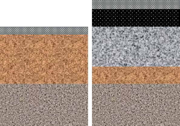
Following pavement-remaining life calculations, the recommended action for this section was 50 mm mill and repave; i.e.
These sections required rehabilitation. An asphalt inlay was chosen as pavement-rehabilitation measure. Analysis showed that it would be necessary to mill off the existing asphalt and 40 mm of the granular basecourse to obtain a pavement structure meeting the design requirements.
This section of the local road not only required an asphalt inlay, but due to the low subbase modulus also in situ ripping and recompacting of the remainder of the existing granular basecourse and the top portion of the subbase, after removal of 225 mm.
TABLE 6 Pavement-Rehabilitation
Kyle Arndt* argues for companies investing in plastic road innovation to protect the resulting technologies with intellectual property rights
Innovation within the road sector must be considered a key weapon in the battle against the growing problem of what to do with plastic waste. Much innovation is already going on. But to bring the resulting muchneeded technologies to market on a viable commercial basis, the innovation will have to be protected through intellectual property rights.
Companies in the US have started to embrace three types of roadway plastics. e rst technique requires the addition of re ned plastic pellets to hot-mix asphalt. e second involves grinding o the top surface
of roads and adding urethane while a third type is roads that are made from purely recycled plastic.
California-based TechniSoil is mixing recycled asphalt with a methylene diphenyl diisocyanate (MDI)-based urethane in a technique that was tested by the University of Nevada at Reno for ve years.
In Europe, PlasticRoad, a company based in the Netherlands, believes it has overcome the slippery surface that can result from employing plastic alone through the use of a special coating that creates a rough surface. e company has test sections in place, around 30m-long bicycle paths.
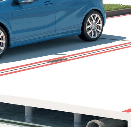
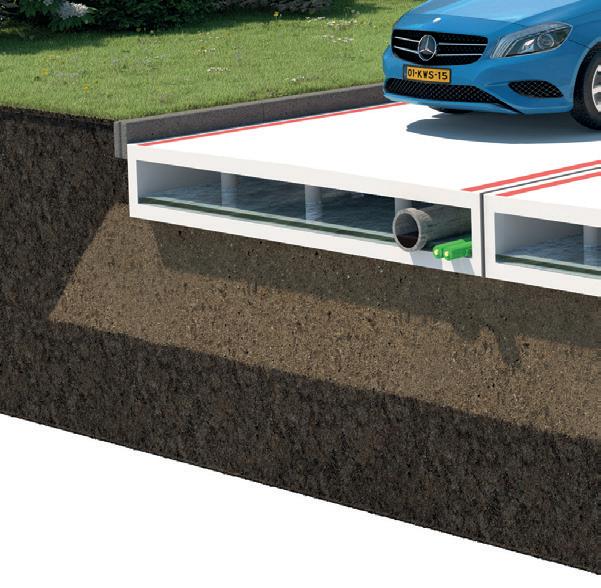
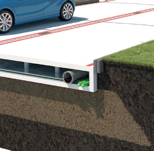
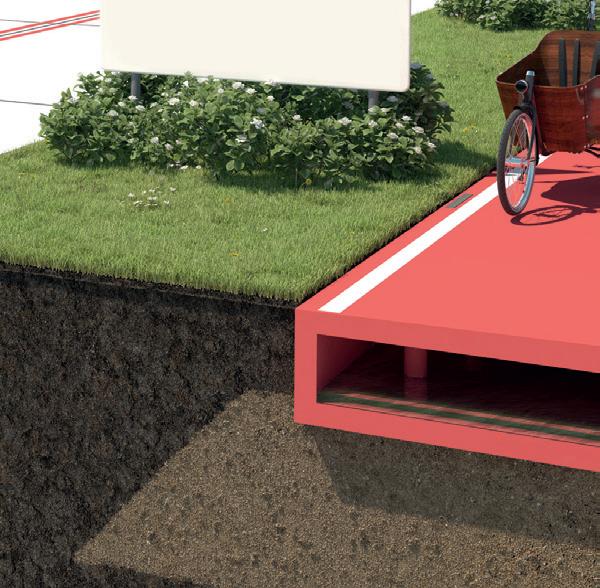
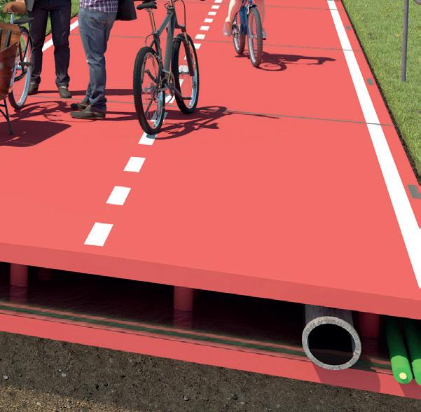
PlasticRoad’s overall concept consists of a prefabricated, modular and hollow road structure based on recycled plastics. e company says that the prefabricated production, a section’s light weight and the modular design make construction and maintenance faster, simpler and more e cient compared to traditional road structures.
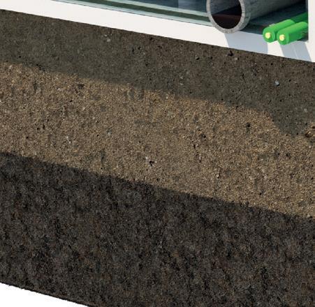
Importantly, the hollow space of a section can be used, if needed, to temporarily store water, thus preventing ooding during extreme precipitation. On a more permanent basis, the hollow space can be used for utility cables and pipes, making redundant the
e hollow space of a plastic road section from Dutch rm Plastic Road can be used for utility cables and pipes (photo courtesy PlasticRoad)
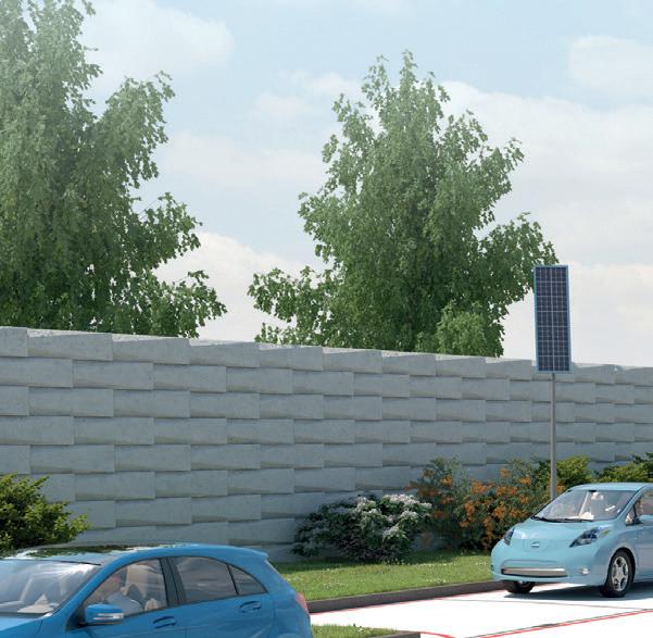
need for utility excavation parallel to the roadway. Similarly, other applications are conceivable, including the installation of tra c-monitoring sensors and systems for electric charging of vehicles.
Scottish company MacRebur has launched the rst of what it says will be many factories which will see plastic granules mixed with an activator to make the plastic bind. e resulting mix will be distributed to asphalt producers. e company said its mix allowed the bitumen used in the production of asphalt to be extended and enhanced, reducing the amount of fossil fuel used.
MacRebur says it avoids using bottles made of PET which stands for polyethylene terephthalate, a form of polyester similar to the clothing fabric. PET can be extruded or moulded into plastic bottles and containers for packaging foods and beverages, personal care products, and many other consumer products. PET is easily recycled so MacRebur says that it instead focusses on using the plastic waste that is destined to be buried in the ground.
MacRebur has recently used its technology for roads throughout a Spring eld Properties housing development in the Scottish town of Elgin. e company believes that the roads are more durable and capable of coping better with weather changes. is reduces cracks and potholes, making production and repairs with smaller carbon footprints.
MacRebur’s technology also means the road can be recycled at the end of its lifespan. A 1km stretch of road made with MacRebur’s environmentally friendly mix would use the equivalent of about 684,000 plastic bottles or 1.8m single-use plastic bags.
e ability to own and protect plastic road innovation will underpin its future value and so IP – intellectual property - should be considered central to the business strategy of new entrants to this market. Indeed, MacRebur has already led at least two patent applications directed to methods of producing a plastic road-making material and a road made from the material in order to help try and protect their innovation. Each component may e ectively increase
NAPA: US ASPHALT PAVEMENT SURVEY
the value of the innovation, so it is therefore crucial that those components are captured and protected throughout the development process. Undoubtedly, a signi cant amount of nancial investment is required to bring new innovations to market. If IP is not in place to safeguard that investment, competitors may seek to copy ideas, which can in turn reduce the funds that the innovators are able to plough back into their business for the development of new methods, including lifecycle analysis of new road surfaces.
*Kyle Arndt holds a masters degree in physics and is a chartered (UK) and European patent attorney specialising in his eld of study. He is with Marks & Clerk, a global intellectual property advisor based in Scotland. e rm’s patent attorneys all have scienti c or engineering backgrounds while its trade mark attorneys advise on all areas of brand protection.
The average percentage of RAP in new asphalt pavement mixtures in the US was 21.1%, a new high, according to the latest survey from the National Asphalt Pavement Association*
The objective of this survey, rst conducted for the 2009 and 2010 construction seasons, was to quantify the use of recycled materials, primarily RAP (reclaimed asphalt pavement) and RAS (reclaimed asphalt shingles), as well as the use of WMA (warm mix asphalt technologies) by the asphalt pavement industry. For the 2018 construction season, the National Asphalt Pavement Association conducted a voluntary survey of asphalt mixture producers across the US on tons produced, along with a survey of state asphalt pavement associations (SAPAs) regarding total tons of asphalt pavement mixture produced in their state. Asphalt mixture producers from 49 states, two US territories and the capital region District of Columbia completed the survey272 companies with 1,328 production plants are represented. is is the largest number of companies and plants to participate in the
survey since its inception.
e reported total asphalt mixture for 2018 was 189.6 million tons and the average tons produced per plant has continued to rise steadily since 2013. A degree of uctuation in year-to-year comparisons of data is in uenced by which companies responded to the 2018 construction season survey versus prior-year survey respondents. For the 2018 construction season survey, there was a 12.4% increase in the total number of companies responding and a 14.6% increase in the number of plants; 29% of companies and more than 30% of the plants responding in 2018 did not participate in the 2017 survey. However, nearly 80% of the 2017 construction season respondents also completed the 2018 survey.
e use of RAP and RAS in asphalt pavements can reduce the amount of new asphalt binder and aggregates required in mixtures, which can help stabilise the
price of asphalt mixtures and save natural resources. Other recycled materials commonly incorporated into asphalt pavements include recycled tyre rubber (RTR), steel and blast furnace slags and cellulose bres.
RECLAIMED ASPHALT PAVEMENT
e overwhelming majority of RAP is used in hot-mix asphalt (HMA) or warm-mix asphalt (WMA) mixtures, which is the most optimal use of RAP. e tons used in cold-mix asphalt data may include some CCPR (cold central plant recycling) of RAP, but the survey does not speci cally record the use of CCPR or in-place recycling technologies.
From the 2017 to 2018 construction season, the amount of RAP used in HMA/WMA increased from 76.2 to 82.2 million tons. e average percent RAP used in asphalt mixtures increased from 20.1% in 2017 to 21.1 in 2018.
For 2018, more than 97% of companies
• Balanced Mix Design/Mixture Performance Testing
responding to the survey reported using RAP. is was a slight decrease from the 98% of companies reporting using RAP in 2016 and 2017, the 100% of companies reporting using RAP in 2013 and 2014 and the 99% of companies reporting RAP use in the 2015 survey.
Placement of RAP in construction and demolition land lls is rare. Since the beginning of the survey in 2009, the average amount of RAP land lled is less than 115,000 tons per year. In 2018, just 12,120 tons, about 0.012%, of RAP was land lled. e amount of RAP accepted during the 2018 construction season saved about 55.3 million cubic yards of land ll.
RECLAIMED ASPHALT SHINGLES
During the 2018 construction season, the total estimated amount of unprocessed and processed shingles received by producers was 1.32 million tons; this is more than the combined amount of RAS used in asphalt mixtures (1,053,000 tons) and in aggregate (50,000 tons) used that year. is is a 5.9% increase from the 1.25 million total tons of RAS from all sources accepted during the 2017 construction season. e use of 1.053 million tons of RAS in asphalt pavement mixtures during 2018 is a 12.5% increase from the 980,000 tons used in 2017.
From the 2012 to 2014 construction seasons, producers reported using RAS in greater quantities than they accepted. When this trend was rst noticed, producers were contacted to con rm the reported values. All producers contacted indicated they either had RAS stockpiled or were purchasing RAS from shingle processors. To capture the volume of processed shingles accepted by producers, the 2015 survey began asking producers, “How many tons of processed shingles were accepted/ delivered to your facilities in the state?”.
Beginning with the 2017 construction season survey, producers were asked to report the tons of unprocessed PCAS (post-consumer asphalt shingles), unprocessed MWAS (manufacturing waste asphalt shingles) and processed RAS
accepted separately.
• Increased Utilisation in Lower Layers/Layered Design
• Fractionating RAP
• Work with Dot on Speci cation
• Increased/Excellent QC of Recycled Materials
• Binder Grade Bumping
• High RAP Speci cation for Low-Volume Roads
ere was a signi cant (38%) increase in the acceptance of processed shingles in 2018 compared to 2017, leading to a 6% increase in the total amount of RAS accepted during the 2018 construction season. However, the total estimated amount of unprocessed shingles accepted by producers declined 5% from 935,000 tons in 2017 to 890,000 tons in 2018. e drop in unprocessed shingles was due to a 9.6% decline in accepted PCAS, which fell from 591,000 tons in 2017 to 534,000 tons in 2018. Acceptance of MWAS, however, increased 3.5% during the same time period, rising from 344,000 tons in 2017 to 356,000 tons in 2018.
No RAS accepted by producers was reported as land lled during the 2018 construction season. By accepting 890,00 tons of unprocessed RAS from both PCAS and MWAS sources, asphalt mixture producers saved about 540,000 cubic yards of land ll space.
According to the Asphalt Roo ng Manufacturers Association in 2015, about 13.2 million tons of waste shingles are generated annually — about 12 million tons of PCAS and 1.2 million tons of MWAS. erefore, asphalt mixture producers in 2018 diverted about 10% of the total available supply of waste shingles from land lls.
e number of companies using RAS increased from 64 in 2017 to 67 during the 2018 construction season. e percentage of producers reporting use of RAS decreased from 27% to 25% in 2018.
POTENTIAL RAP AND RAS
For the 2018 construction season survey, state asphalt pavement associations were asked if they felt there were opportunities for greater use of recycled materials, primarily RAP and RAS, in their state. Of the 26 SAPAs providing a response, 77% said yes. e SAPAs were also asked to provide two ways that agencies and industry could work to increase the use of recycled materials. As can be seen in Figure 13, more than half of respondents felt this could be done with the use of balanced mix design
and mixture performance testing (29%) or by increasing recycled material content in lower pavement layers (23%). An additional 18% felt that increased fractionation of RAP would help increase RAP usage.
Speci cation changes, improved recycled materials quality control and binder grade bumping rounded out the responses. is di ers from the 2017 survey where respondents were asked about what limits the use of RAP and RAS in their state and the most frequent responses were speci cation limits (39% for RAP; 47% for RAS) and the availability of RAP (19%) and RAS (13%).
QUALITY ISSUES
For more than three decades, two guiding principles of asphalt recycling have been that asphalt mixtures containing recycled materials should 1) meet the same requirements as asphalt mixtures with all virgin materials, and 2) perform equal to or better than asphalt mixtures with all virgin materials. is is at the heart of the so-called ‘ ree R’s of Recycling’ – recycled materials should provide environmental, economic and engineering bene ts.
Quality recycled mixtures have been successfully designed and produced for many years. When successfully engineered, designed, produced and constructed, the proof is in performance. A recent study comparing the performance of recycled versus virgin mixtures based on long-term pavement performance (LTPP) data from 16 US states and two Canadian provinces shows that overlays containing at least 30% RAP performed equal to overlays using virgin mixtures.
At the NCAT Test Track, test sections containing 50% RAP using Superpave mixture design procedures for each layer outperformed companion test sections with all virgin materials in all pavement performance measures. However, as the amount of recycled materials in asphalt pavement mixtures increase, additional considerations for material handling, engineering, mixture design,
quality and performance testing become more important. In particular, RAP and RAS should be tested and classi ed to determine the amount, properties and quality of available asphalt binder. e absorbability of RAP aggregate should also be tested and determined. ese values have an impact on pavement performance and are important to assess when developing a high recycled content mixture design. In some cases, it may be necessary to make use of recycling agents or a so er asphalt binder to ensure the nal mixture design delivers the desired level of product performance.
WARM-MIX ASPHALT
Prior to the 2018 construction season, producers were asked to report primarily the use of WMA technologies to reduce production temperatures by at least 10°F (-12°C) from typical mixture production temperatures. However, because of potential compaction, antistrip, and workability bene ts, the use of WMA technologies at HMA temperatures is common. To better understand the use of WMA technologies at di erent temperatures, the 2018 construction season survey asked additional questions to ensure disaggregation of WMA technology use at di erent temperatures. e results indicate that prior survey reports have better captured the use of WMA technologies than the use of WMA technologies at reduced temperature.
e percentage of companies reporting the use of WMA technologies saw rapid increases
from the 2009 to 2011 construction seasons, but has held at between 68% and 78% of respondents from the 2011 to 2018 construction seasons. Increases in tonnage with WMA technologies as a percent of total tonnage have generally plateaued between 2013 and 2016. e 2018 construction season, however, had a 7% increase in the production of asphalt with WMA technologies to 157.7 million tons, 40.5% of total asphalt pavement tonnage. A total of 185 companies, 68% of respondents, reported using WMA technologies during 2018.
OTHER FINDINGS
e use of so er binders and recycling agents with mixtures incorporating RAP and RAS was reported nationwide. ere was little correlation between the level of RAP and RAS used and the use of so er binders and/or recycling agents.
Other recycled materials commonly reported as being used in asphalt mixtures during the 2018 construction season were recycled tyre rubber, blast furnace slag, steel slag, and cellulose bres. Recycled materials less commonly reported as being used in asphalt mixtures included y ash, foundry sand, carbon bres, crushed concrete aggregates, and start-up waste.
1.8 million tons of other recycled materials was reported as being used in nearly 12.3 million tons of asphalt mixtures by 79 companies in 31 states during the 2018 construction season.
* e full survey is available for download free on: www.asphaltpavement.org/recycling
OTHER RECYCLED MATERIALS
• A reported total of nearly 1.8 million tons of other recycled materials was used in nearly 12.3 million tons of asphalt mixtures by 79 companies in 31 states.
• Twenty-one producers from 11 states used recycled tyre rubber (RTR) in asphalt mixtures in 2018. The total reported tons of asphalt mixture using RTR increased 66% from 2017 to 1,621,000 tons in 2018.
• Producers in 12 states used steel or blast furnace slags and one state reported using foundry sand in 2018. Compared to reported use in 2017, the reported tons of mixtures including steel slag and mixtures including blast furnace slag increased dramatically in 2018. Reported use of these materials was concentrated along the Mississippi and Ohio River Valleys, where much of US steel and iron production is concentrated.
• Producers in four states used y ash in asphalt mixtures in 2018. Fly ash was the only coal combustion product (CCP) reported used in asphalt pavement mixtures.
• Producers in 23 states reported use of more than 8,000 tons of recycled cellulose bre in more than 1.8 million tons of asphalt pavement mixtures.
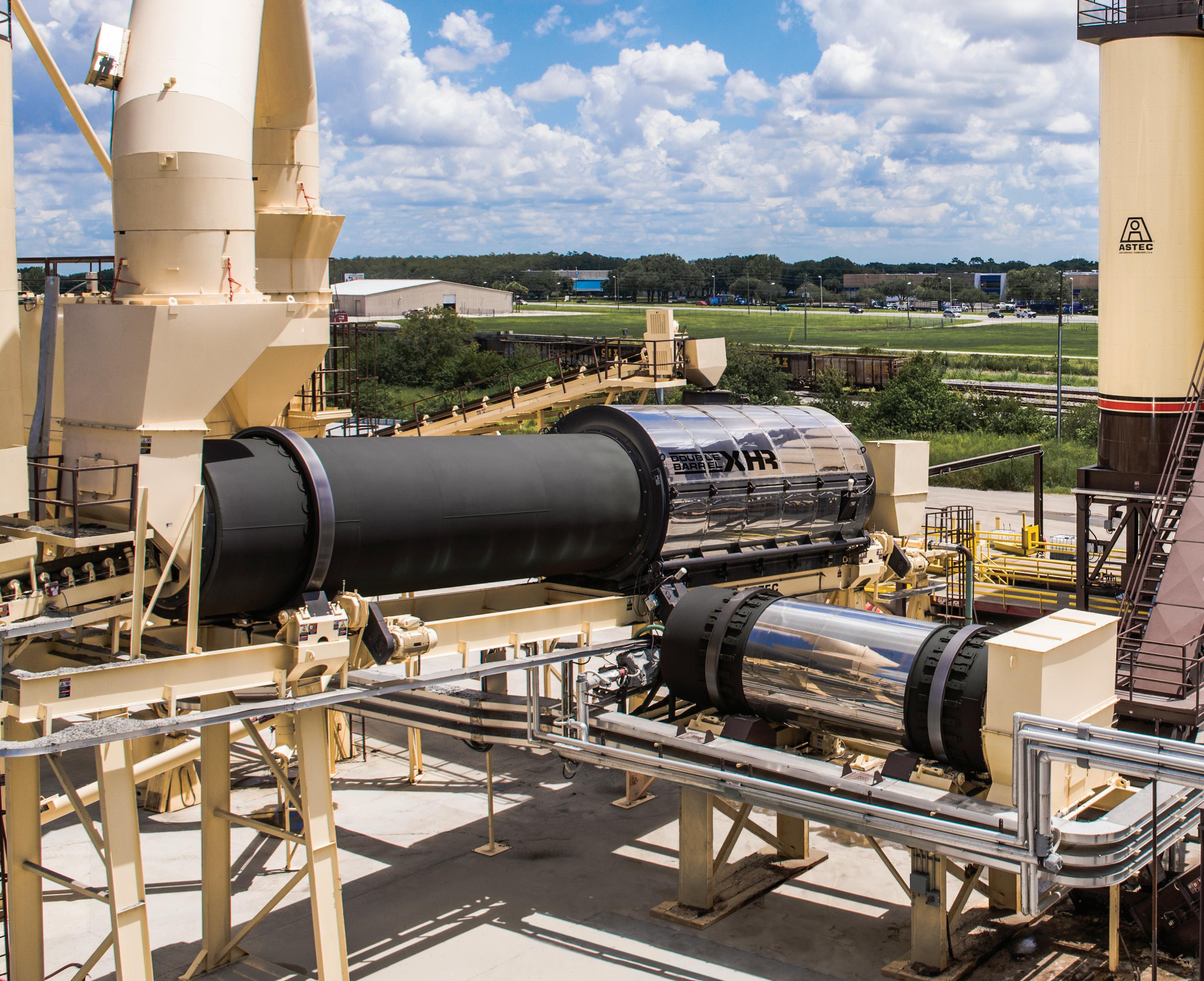
ASTEC DOUBLE BARREL® XHRTM
HIGH RAP AGGREGATE DRYER WITH EXTERNAL MIXER
The Astec Double Barrel XHR High RAP aggregate dryer with external asphalt mixer achieves a quality high RAP mix.
To achieve this quality mix, it utilizes both an outer chamber on the drum and an external mixer with the addition of the V-Pac™ Stack Temperature Control System to maintain as low an exhaust temperature as possible when running high RAP content. A stainless-steel drum with stainless-steel combustion flights withstand the higher temperatures associated with running high RAP. The Astec warm mix system comes standard on all Double Barrel XHR mixing systems.
For more information visit us at www.astecinc.com/DBXHR
A unique approach to asphalt mixing technology.
RECYCLE
Can process asphalt mixes with up to 70% RAP* content while maintaining zero opacity at the stack.
V-PACTM
Maintains low exhaust temperature when running high RAP content.
OUTER MIXING CHAMBER
Gently mixes recycle with dry hot aggregate maximizing heat and binder transfer.
EXTERNAL MIXER
Vigorously mixes virgin liquid asphalt cement, as well as other admixtures.
*at 3% moisture content
AUTOMATED CONTINUOUS INTEGRATED PAVEMENT CONDITION DATA
Use of an Intelligent Pavement Assessment Vehicle (iPAVe) for continuous surface measurement is gaining ground in South Africa*
The South African road network, of 750,000km, of which 165,000km are all-weather roads, is the tenthlargest in the world. Networklevel road condition assessments for input to computerised road asset management systems (RAMS), have been carried out on a systematic basis since the mid 1980’s. While considerable advancements in data analysis methods have been made in this time, concurrent development in the collection of road condition data has not happened. This vital aspect is still done manually.
In 2015, VNA Consulting acquired an Intelligent Pavement Assessment Vehicle (iPAVe) to collect continuous, integrated and synchronised surface, structural and
of Transport (FSDPRT) to isolate and interrogate pavement distress mechanisms on a close scale, assess remaining pavement and
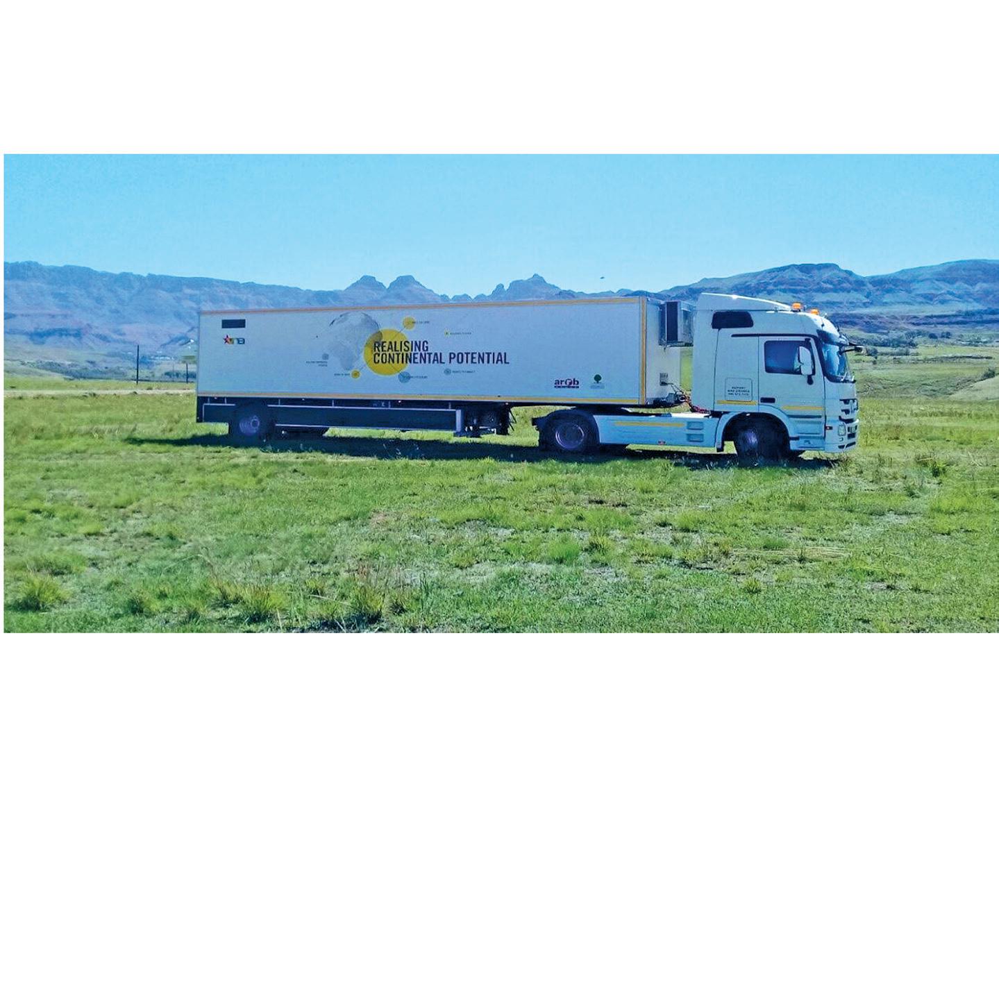
The Intelligent Pavement Assessment Vehicle (iPAVe) is considered to be an advancement in pavement management as it is able to collect both surface and structural pavement condition data at road speeds of up to 80kph. The iPAVe, owned and operated by VNA, integrates the traffic speed deflectometer (TSD) developed by Greenwood Engineering with the Automated Road Rehabilitation Business (ARRB) Systems Hawkeye 2000 platform. It is one of six iPAVe vehicles operated globally.
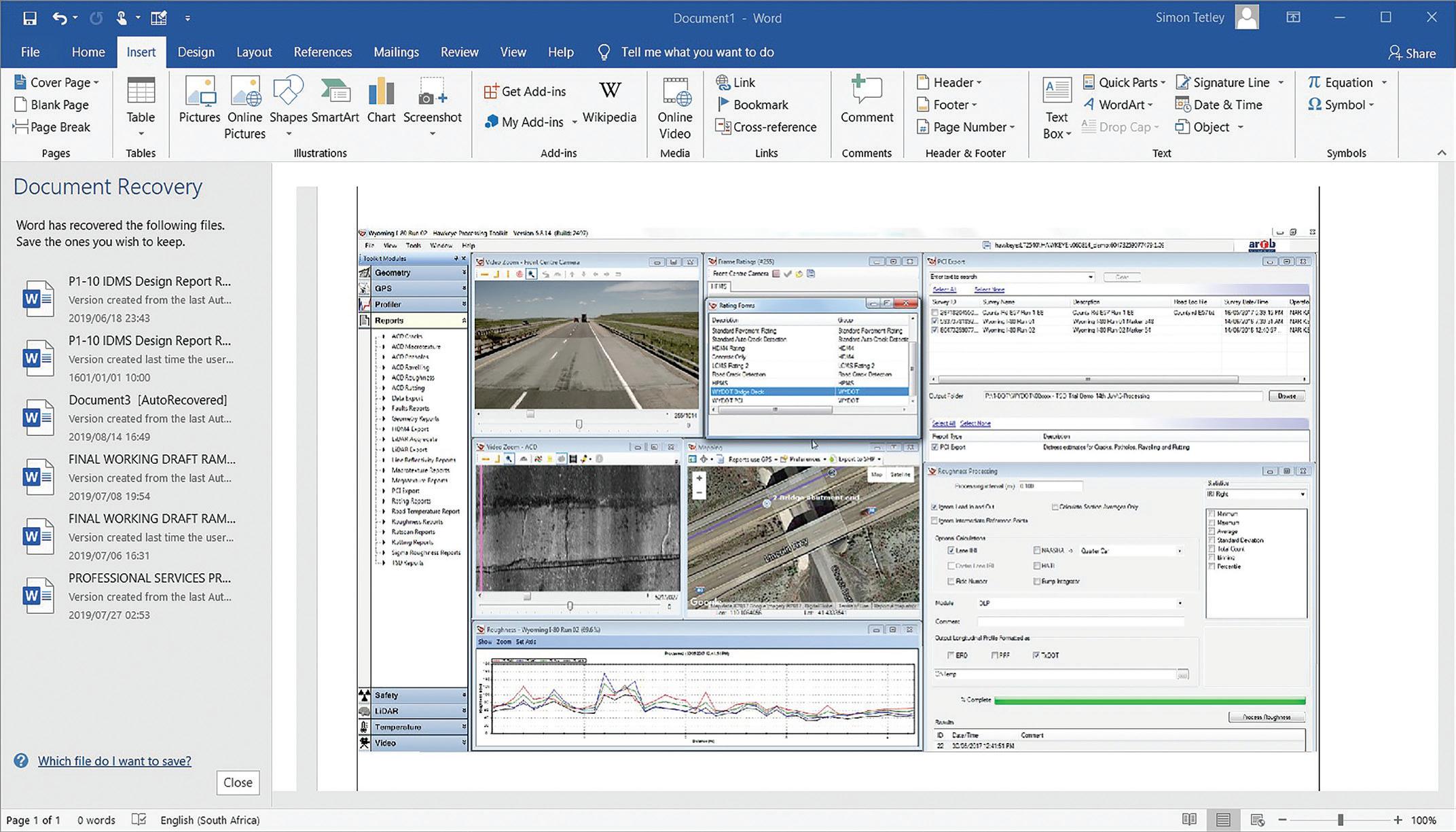
LEFT: A data viewing and analysis dashboard in the Hawkeye toolkit allows for concurrent analysis and interrogation of individual spatially referenced condition data sets
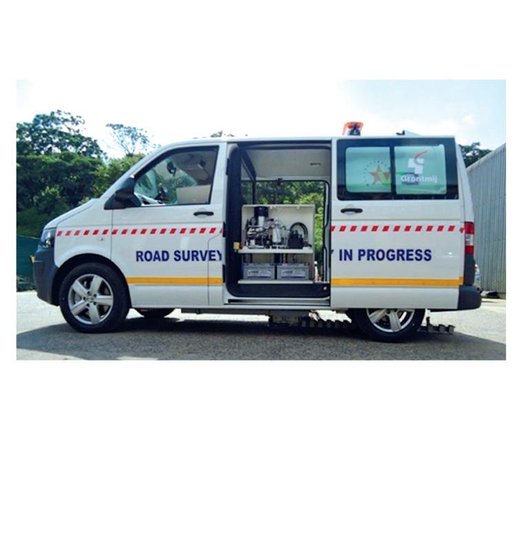
On the road with the iPAVe in South Africa
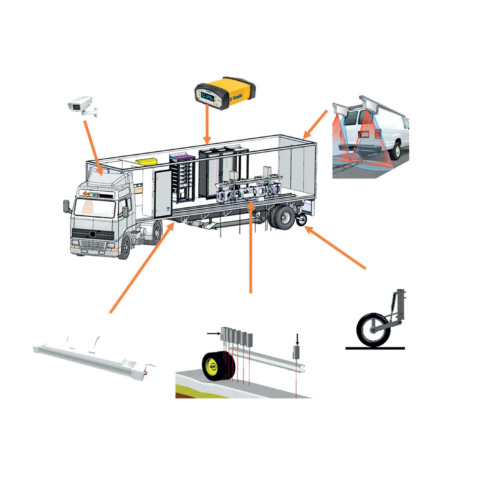
The iPAVe’s TSD uses high-precision Doppler lasers to measure the pavement deflection velocity from which the deflection bowl is calculated, while the Hawkeye platform is responsible for measuring road surface characteristics such as cracking, potholes/failures, roughness, rutting, texture and geometry, together with spatial information and digital imaging. These two subsystems are synchronised to successfully create an integrated survey vehicle with the integration of the various measurements being managed by ARRB Systems’ proprietary software.
The KZN DoT and the FSDPRT have adopted the system for their network-level road assessments.
SURFACE AND SPATIAL IMAGING
The iPAVe is fitted with five digital imaging cameras which are used to record highresolution images of the pavement and road assets. The cameras are orientated to ensure that a wide field of view is recorded and are all calibrated for scale measurement and geospatial referencing. Road surface information is used for the post rating of the road while the spatial images provide essential information on roadside furniture, structures, signage, drainage, safety assets and road prism.
A global positioning satellite (GPS) system provides accurate and synchronised coordinated spatial data of the vertical and horizontal road alignment.
The TSD measures pavement deflection in the outside wheel track at up to 80kph. This removes not only the requirement for traffic management and significantly reduces the safety risk, but as the measurement is practically continuous there is full coverage of the network which eliminates the possibility/probability of omitting any deficient pavement sections during testing and educated guesswork during data analysis. Automatic crack detection (ACD) using two laser crack management systems (LCMS) is an integral component of the iPAVe. The laser units project a 4m-wide laser line across the pavement, with the laser image being captured by two 3D cameras mounted off-axis to the laser light source. The cameras interpret the distortions and each frame is analysed to determine the presence and type of cracking on the pavement surface.
Continuous riding quality data, in the form of the International Roughness Index (IRI) standard, is derived from the digital laser profiler (DLP) which uses lasers and an accelerometer located in each wheel path to
ABOVE: The Intelligent Pavement Assessment Vehicle (iPAVe) can collect both surface and structural pavement condition data at road speeds up to 80kph. BELOW: Falling weight deflectometer with internal mechanism
which establishes the transverse road profile to determine both the rut depth and characteristics. The processing software allows for differentiation between lane and wheel-path rutting.
TEXTURE MEASUREMENTS
Surface macro texture is continuously measured using three lasers; one in each wheel path and a third in between the wheel tracks for comparison purposes. The macro texture is reported in terms of mean profile depth (MPD).
In summary, while 100% fully automated road condition assessments are probably not possible – due to the need for human input –the iPAVe has been found to provide a level of automation previously not possible.
average of 4,600km per year using FWD. While the FWD typically tests at a 200m interval for network-level surveys, the iPAVe is providing continuous measurement which, at a 5m average, equates to four million test points for iPAVe as against 23,000 for FWD.
The logical progression towards full automation is to incorporate artificial intelligence capable of identifying and rating the individual pavement distress items, thereby removing the serious effects of subjective condition rating. Work on this quantum leap has been ongoing in South Africa and other countries for some time and it is probable that full-spectrum automated road condition data acquisition will be a reality in the near future and become the standard as opposed to the exception.
HAWKEYE TOOLKIT
As noted, the KZN DoT has commissioned the iPAVe system to provide road condition data for input to their RAMS. The data viewing and analysis dashboard, as provided in the Hawkeye toolkit, allows for concurrent analysis and interrogation of individual spatially referenced condition data sets. This has proven to be an essential component of the KZN DoT RAMS, even though not actually a module of the system.
As for network-level assessments, the status quo for project-level design investigations is to carry out a visual
ACD
GPS
Digital camera (front and rear)
DMI
Measurement beam
Digital laser profiler
Front laser-mounted beam
Doppler 7 Doppler 1
assessment (more detailed than the networklevel visual) and use FWD for structural testing. An NSV (network survey vehicle) survey for ride quality and rutting may or may not be done depending on the class of road and the responsible road agency.
A recent design project for the rehabilitation of a major urban arterial road in the Eastern Cape Province of South Africa clearly illustrated the bene t of using iPAVe.
e section of road is a heavily tra cked 7.5km dual carriageway through a major industrial area in the city of East London.
e consulting engineer’s brief for the testing was for FWD testing in both lanes at 100m-spacing, together with an NSV survey to measure rutting and riding quality. It was suggested to the design engineer that an iPAVe survey would be bene cial to the design process and this was agreed to – on the condition that this was to be in addition, and not instead of, the FWD/NSV investigation.
e FWD/NSV survey took nine hours with full tra c accommodation while the iPAVe survey took 45 minutes with no disruption to tra c. Also, the consolidated iPAVe data was provided to the design engineer before the FWD survey was even nished.
As well, a number of areas that fell in between the FWD points were clearly identi ed as signi cantly less sti than adjoining portions. e designer was able to use this critical information to plan the subsequent intrusive materials investigation.
e most bene cial aspect of the iPAVe over the FWD is that it is practically continuous, enabling the design engineer to de ne test-spacing of the de ection points (and other test data) as is required.
Having the ability to zoom in to accurately isolate potential problematic road sections means that remedial actions can be applied exactly where they are needed, rather than applying a holistic intervention between points that are hundreds of metres apart. Otherwise, substandard pavement sections would not have been identi ed, with a good probability of additional expenditure being incurred at construction stage or, even worse, once the new road was opened.
iPAVe DURING CONSTRUCTION
In addition to general design-stage use, the iPAVe has also been used at project level to undertake “forensic investigations on roads during construction”. One such project is the major rehabilitation of a 20km portion of Provincial Main Road P21-1 between
Durban and Pietermaritzburg. is is a major link between the N2 and N3 freeways. e cumulative design tra c-loading for the 15year structural design period was 11 Million Equivalent 80kn Standard Axles (MESA).
e pavement design for the project included a new 40mm asphalt surface and an 80mm asphalt base course. e existing surface plus 260mm of base course in-situ is recycled to new 300mm cement-stabilised sub-base (Figure 1).
Construction started in 2016 and progressed well until industrial action and other issues resulted in an eight-month delay. During this period, it was necessary to open the road with a number of newly constructed sections being exposed to tra c without the 40mm surfacing layer in place.
e eight-month premature tra c load, together with an even longer period where the more porous base mix asphalt was exposed, resulted in fatigue and blockcracking over certain sections. Following detailed visual inspections, it was clear that the a ected areas – kilometres 8.5 to 11 and also kilometres 13 to 16 – would require remedial action. But how much of the new pavement structure could be saved?
Visual impression, together with the presence of block-cracking and isolated pumping suggested the stabilised base was cracked. e initial consensus was that the entire 380mm-thick base and sub-base should be re-built – at a signi cant cost to the road authority.
It was decided to undertake an iPAVe survey of not just the a ected areas but the entire contract length. e section of the road under consideration, for example kilometres 0 to 20, was exhibiting a sti -to-very-sti behaviour with the majority of de ections below 300 microns and generally around 150 microns.
e areas with maximum de ection measurements in excess of 300 microns were on sections of the project that had not yet been rehabilitated, such as kilometres 0 to 1
New 40mm asphalt surfacing and 80mm asphalt base course
Existing surfacing plus 260mm of base course in-situ recycled to new 300mm cement-stabilised sub-base
and kilometres 17 to 18, or were the subject of rejection due to quality control issues (as from kilometres 2.1 to 2.45). Areas of concern, namely kilometres 8.5 to 11 and kilometres 13 to 16, generally exhibited maximum de ection measurements of between 200 and 300 microns with isolated spikes of up to 500 microns.
It was also interesting to note the excellent repeatability of the measurements and the signi cant reduction in maximum de ection between kilometres 17 and 18 where the new sub-base and base were constructed in the period between the two test dates.
Simultaneous riding quality, rut depth and crack detection measurements were also undertaken. Subsequent analysis of the combined data sets indicated that the rehabilitated sections of the contract had a bearing capacity exceeding the design tra cloading. is included, to a lesser extent, areas exhibiting the fatigue and block-cracking and indicated that full-depth reconstruction of the latter would not be required. Instead, selective asphalt base mill-and- ll repairs were done out at a signi cantly reduced time and nancial cost to the road authority.
FWD testing would have given a similar result in terms of measuring pavement de ection in this case study. But the iPAVe can produce continuous data, meaning that critical pavement sections can be identi ed within metres as opposed to hundreds of metres. is, in addition to the speed of testing, concurrent supporting data gathering and the fact that tra c accommodation is not required, clearly indicates that automated continuous and integrated road condition data collection has broken the mould.
* e authors are Simon Tetley and Tony Lewis at VNA Consulting South Africa and Yeshveer Balaram at ARRB Systems South Africa. e article is an abbreviated version of their paper presented at the 18th Australian Asphalt Pavement Association (AAPA) International Flexible Pavements Conference in Sydney this year.
Figure 1: Existing Pavement and New Pavement Structure
Asphalt paving and compaction technology has seen notable developments for 2019, with new machines and technology coming to market - Mike Woof writes
COMPACT PAVERS
Compact asphalt pavers are versatile machines, useful for road repairs and utilities jobs, as well as paving cycle lanes, pedestrian footpaths and underground or multi-story carparks.
One of the smallest units on the market is Ammann’s diminutive AFW150-2 model, which is designed for paving work such
for such narrow paving widths is for laying asphalt in between tram tracks on urban roads. Meanwhile, the machine can be used for a maximum paving width of 1.3m with the screed at full hydraulic extension. Using bolt-on attachments tted to the screed, maximum paving width is 1.65m. e machine is available with a vibrating screed only.
comes from an emissions-compliant diesel delivering 55.4kW. When the screed and hopper wings are retracted, the machine can pass through a 1.2m wide doorway. e maximum paving width is 3.4m. A tamper bar screed is tted as standard. e machine has a novel dual-position platform, with the operator able to stand up on the deck for an all-round view of the working area, hopper and screed. Using the lower position, meanwhile, allows the operator to watch the screed more closely.
Carlson is o ering its wheeled CP65 paver, which features 4x6 drive and a tamper bar screed. e ECZ 34TV screed o ers hydraulic extension from 1.8-3.4m, with a maximum paving width of 4.5m using bolt-on extensions, while minimum pave width is 750mm. A vibratory-only screed, the ECZ34 V, is available for the North American market, tted to the CP60 paver with 2x6 drive. e machine weighs 9.35tonnes and can deliver up to 250tonnes/ hour. Power comes from a Deutz diesel rated at 55kW, with a Tier 4 Final/Stage V version for Europe and North America and a Tier 3 variant for lesser-regulated markets.
Dynapac’s proven F1200C and F1200CS models o er paving widths of 1.2-3.1m and throughputs of up to 300tonnes/hour. Both machines have Deutz diesels delivering 54kW and available with Tier 3 or Tier 4 Final variants, as well as a choice of electric or gas
heating for the screeds. e 5.8tonne F1200C has a choice of two screeds with vibration only. e 5.9tonne F1200CS has a choice of two screeds with tamper bar and vibration.
Vögele’s Super 800 paver is tted with the rm’s AB220 TV screed, which features a tamper bar and vibration. Meanwhile, the rm’s Super 700 model uses the AB 220 V screed with vibration only and is aimed at the North American market. Whether for the AB 220TV or AB 220 V variant, paving widths range from 1.2-2.2m. Bolt-on extensions to the AB 220 V allow paving widths of 3.2m while bolt-on extensions for the AB 220 TV variant allow paving widths up to 3.5m. Power comes from a Deutz diesel engine rated at 55.4kW, which allows a maximum paving speed of 30m/min.
Volvo Construction Equipment’s (Volvo CE) is introducing two new pavers, the P2820D ABG and P2870D ABG, the most compact pavers in the line-up. e rm says that the P2820D ABG and P2870D ABG are quiet in operation, suiting them to inner-city projects such as cycle tracks and parking lots. Highly e cient, the new machines also promise low fuel consumption and low CO² emissions. With their 55kW Volvo engines and well-matched hydraulics, the pavers have e cient drives. Customers can choose between the more common dual conveyor or Volvo’s novel single conveyor. Options include individually operated hopper wings, enabling each unit to pave closer to obstacles, and an electro-hydraulic foldable roof.
MID-HIGHWAY CLASS
Bomag is o ering a novel control system on its BF700 model. is features all the controls tted to the arm rests of the seat, a layout said to reduce operator fatigue. Visibility is also said to be good as the seat can be rotated so as to see either the hopper or screed, while it can also be moved from side to side.
Sumitomo aims to boost brand awareness with its prototype HA60C-11 paver. Operating weight is 15tonnes and the machine is powered by a Yanmar diesel delivering 110kW, which is Stage V compliant. e paving speed is 20m/ min while travel speed is 3km/h. e paver HA60C-11 comes with Sumitomo’s successful J-Paver 2360 screed. e paving width is variable from 2.3-6m without the need for any bolt-ons. Updates to the screed have also made it more rugged and rigid, improving paving accuracy. e machine is said to be easy to use, with a new wide-deck design and twin seats that can be swung over either side, allowing better visibility of the screed edges.
MATERIAL TRANSFER
Roadtec is now offering a new material transfer vehicle (MTV) in the shape of its MTV 1105e model. The machine weighs in at 21.7tonnes unladen and features power from a Cummins QSB6.7 diesel, rated at 186kW and which meets Tier 4 Final/Stage V emissions requirements. This is the rst time that Roadtec
Bomag’s BF700 paver features a novel control layout
has offered a tracked MTV. The rm says that it has achieved this using proven components and systems from its existing product line and bringing these together in a new con guration to meet market demand for a tracked MTV. The machine does not have the remixing capability of its stable mate, the Shuttle
Buggy, and instead utilises the proven chassis of the rm’s wheeled MTV 1100 model. Meanwhile the proven tracked undercarriage system from the rm’s own RP 195e asphalt paver has been married to the MTV 1100 chassis, to deliver this new model variant.
Roadtec www.roadtec.com
e new Volvo CE models are available in wheeled and tracked variants
Vögele’s giant SUPER 3000-3(i) paver can pave widths up to a record 18m. This machine can pave multiple highway lanes simultaneously and also suits airport runway paving. Power for the SUPER 3000-3(i) comes from a six-cylinder diesel rated at 354kW and it has a design throughput of 1,800tonnes/hour.
Customers can choose either the SB 300 or SB 350 fixed screeds, which can be fitted with hydraulically adjustable ends providing from 0-1.25m of extension on either side. The SB 300 replaces the earlier SB 250, while the SB 350 has been designed specifically for use with the SUPER 3000-3(i). The tamper bar screeds have a new system that allows the operator to change stroke hydraulically to suit varied layer thicknesses.
The screeds also benefit from an improved heating system that cuts warming-up time from cold by 50%. Another innovative feature of the SUPER 3000-3(i) is the design that provides the operator with infinite height adjustment at the rear of the chassis for paving thick asphalt layers.
As with other Vögele pavers, the SUPER 3000-3(i) features the firm’s sophisticated AutoSet Plus package that offers automated functions, PaveDock Assistant communication system and VÖGELE EcoPlus low-emissions package. However, despite its high throughput and 18m maximum paving width, the SUPER 30003(i) paver offers a transport width of just 3m and its canopy can also be folded down, reducing overall height and making it easier to transport.
CHINESE MARKET
Different markets require different machines. Customers in China use similar tamper bar screeds to those in Europe, but emissions requirements are different and material hoppers tend to be bigger.
Dynapac is offering new paver models either developed specifically for the Chinese market or in forms modified to meet the needs of Chinese customers. The firm’s SD2550CS machine is powered by a 194kW Cummins diesel and is available worldwide. However, a special variant is offered for the Chinese market that is equipped with the R300TV or R300TVE fixed screeds.
The highway-class SD2550CS model is a paver capable of a throughput of up to 1,100tonnes/hour. However, for the Chinese market, Dynapac says it fits the machine
with fixed screeds as standard as these are preferred for highways due to the high finish quality. Both the electric- and LPG-heated variants of the basic screed are offered, although Dynapac says that the former outsells the latter by around 2:1. Hydraulic extension systems offering up to 1m extra on each side can be fitted. Dynapac also fits the SD2550CS with a slightly larger hopper, offering a 17tonne capacity.
Designed only for China is Dynapac’s SD2530CS paver, which combines features from the firm’s SD2500 and SD2550CS models. This is designed for urban paving operations with a maximum throughput of 800tonnes/hour and has a screed offering widths from 2.55-10m.
Both machines are offered with the firm’s Dyn@Link fleet-monitoring package, which was introduced to China last year and is said to be attracting strong interest in the market. The machines are also offered with the Truck Assist package, which helps with loading. Lights mounted on the paver tell the truck driver whether the hopper is loaded.
Vögele is widening its product range of pavers for the Chinese market and is now offering the Super 1600L and Super 16003L variants in China, in addition to models such as the existing Super 1880L. As with the Super 1880L, the two new models feature larger hoppers (denoted by the L suffix) than standard pavers for Europe and other markets. This 15tonne hopper capacity allows the pavers to match the bigger asphalt delivery trucks used by Chinese contractors.
The Super 1600L forms part of the firm’s newly established Classic Line, while the Super 1600-3L is in the Premium range. For the moment these machines are being built in the firm’s German factory but will be manufactured at the company’s Chinese
Sumitomo is developing a new wheeled paver
Dynapac offers models designed for the Chinese market only
PAVING ALTERNATIVE
VSS Macropaver has also been active co-developing a new website that gives comprehensive information on microsurfacing techniques. The website, RoadResource.org went live, in mid-2018 and its development was assisted by three major US associations for pavement preservation; Asphalt Emulsion Manufacturers Association (AEMA) and the Asphalt Recycling and Reclaiming Association (ARRA).
Doug Hogue is vice president at VSS Macropaver and explained that the website is not aimed at promoting equipment from any supplier, but is instead intended to raise understanding about microsurfacing. He said that knowledge levels about this can vary widely and that road repair methods can be very localised, even in the US.
The website teaches about emulsion-based processes and which type of processes are applicable to repairs. Hogue said, “We’re still going to see how it’ll be used by agencies. It’s industry-wide and we’re excited by it.”
The information on microsurfacing technology is applicable worldwide, though the website’s cost data is for North America.
facility alongside the Super 1880L in Langfang in the future.
e Classic units can be used for normal urban paving jobs. Meanwhile, the Premium models are aimed at use in applications where site data will be recovered and which require the use of machine control technology.
e Super 1600-3L is being equipped with the AB500 screed while the Super 1600L is tted with the AB480 screed. At full hydraulic extension the AB500 can allow a paving width of up to 5m, while the AB480 reaches 4.8m. Both screeds can be tted with 1.5m bolt-on extensions at either side.
Volvo CE’s P7820DL ABG paver was developed for the Chinese market and features the rm’s latest Electronic Paver Management system – EPM 3, which is said to optimise the paver for speci c applications. From the platform, operators are said to have
good visibility all around the paver, hopper, auger channel and screed. A glazed area on both sides of the platform boosts visibility, while LED work lights and balloon light options allow working in low light.
Two engine variants are available for Chinese emissions regulation, suiting the current China III and future China IV requirements. e Volvo Penta D85 diesel delivers 175kW.
Meanwhile, the paver has its hopper extended by 300mm for the Chinese market. is allows large trucks enough space to feed the paver. e screeds tted to the Volvo P7820DL ABG allow paving widths of up to 11m and can handle a wide range of materials. e machine has a maximum claimed throughput of 900tonnes/hour. Weighing in at 22.5tonnes in standard con guration, the machine has a 15.5tonne capacity hopper.
e Vögele Super 3000-3i o ers a record 18m paving width
A new drive system optimises performance for Ammann’s
Advances in asphalt compaction
offer key bene ts for contractors – Mike Woof writes
The latest asphalt compactors will deliver bene ts for contractors compared with earlier machines. Advances deliver improved quality and nish.
From Ammann comes the ARX 91 articulated tandem roller, which can be used on both thin and thick asphalt layers. is high productivity machine is said to compact asphalt in fewer passes than previous models.
e company claims that the combination of drum dimensions, frequency and amplitude settings is highly versatile. e new drive system and range of compaction settings are said to maximise output and compaction in a minimum of passes. Other bene ts include lower fuel consumption and running costs.
e ARX 91 model weighs in at 9tonnes and is powered by a Cummins BS-III/Tier 3/Stage 3A diesel. Key to the operation of the roller are the e cient hydraulics, traction control system and speed sensors.
e company claims that this set-up allows smooth starts and stops, helping to optimise
mat quality. e engine is mounted in the rear chassis, which helps to reduce vibration and heat in the cabin and improves visibility. It is also available with the Ammann Compaction Expert (ACE), the rm’s proprietary Intelligent Compaction system as an option. is package monitors density and provides feedback, helping to reduce the number of passes, while eliminating the risk of either over- or under-compaction.
A novel development from BOMAG is the choice of drive systems for its popular BW 120 asphalt compactor, which competes in the 1.2m-wide drum class. In addition to two diesel engine options, the rm is o ering a version of the BW 120 that can run on propane gas from cylinders, as well as the potential for an electric variant.
e propane-fuelled variant has the same cost as a standard diesel and runs from standard 11kg gas bottles, which allow a running time of ve hours and are readily available in most markets.
e propane-fuelled model is rated at 30kW and cuts overall emissions by around
50%, with no particulates and minimal tailpipe NOx. e Deutz engine meets the Stage V requirements and has a particulate lter but has no need for more complex a ertreatment. e rm says it is testing the market for the gas-fuelled variant but believes demand could develop in urban areas with ultra-low emission zones.
e electric model features four lithium ion cells and two electric motors, allowing an operating time of 1.5 hours and requiring a recharging time of 1.5 hours. Although this model has zero emissions, it costs two to three times that of the standard diesel model. BOMAG believes the lack of mains power for charging on many sites means the market may not be ready for this option yet.
On a more conventional note, the rm is also o ering the BW 120 with diesels that meet the Stage V emissions requirements.
ere is a model with a Kubota diesel engine
latest compactors
Bomag is o ering a compact machine with a choice of diesels, LPG or electric power
Bomag’s autonomous compactor prototype is highly advanced
delivering 24.3kW, as well as a lower-rated version with an 18.5kW diesel and lower running costs.
The firm is also looking ahead to the future and has unveiled a more radical prototype. BOMAG’s innovative BW 154 compactor is an autonomous machine. Developed in partnership with Trimble, this is able to operate on its own. Sensors around the machine detect whether there is anything in its path and will stop the unit or allow it to steer around obstacles.
Dynapac is introducing its sixth generation of asphalt compactors, the CC4200 - CC6200 models. The firm claims that the machines are easy to operate and offer high manoeuvrability and high-quality compaction. Key features include low-emission engines and high vibration frequencies, as well as an advanced water system.
An improved driving position and visibility are important upgrades. The new generation of Dynapac machines allows the seat and steering module to be swivelled and slide from the left side of the roller to the right to see the drum edges. The seat can also swivel to be rear facing when working backwards.
The machine also combines articulated steering with a steerable rear drum and now an offset of up to 500mm.
High vibration frequency compaction is
said to suit duties in thin layers, which need to be compacted fast because they cool off quickly. The rollers can also be used for thick layers with high amplitude and conventional vibration frequencies.
Different engines are available to suit local market requirements with Stage IV/Tier 4 Final units for Europe and North America and StageIIIA/Tier 3 for segments without the availability of low-sulphur fuels.
Dynapac is also offering its latest oscillation compaction system. The firm says it has focused on wear resistance and serviceability. The Dynapac CO4200 has one vibrating drum with two vibration amplitudes and one oscillating drum. The operator can select the system most suitable for the application. The oscillation system is suited to compacting thin lifts, bridge decks and working in urban areas.
Arch-rival Hamm has also been carrying out development work on autonomous compaction systems. The firm has been doing testing at its own proving ground, which lies alongside the factory.
On a rather more conventional note, Hamm is improving the performance of one of its oscillatory-type asphalt compactors. The DV+ 90i VS-OS model is able to cope with tighter turns due to the fitting of split drums. As a result, the machine can make a
LEFT: Dynapac is offering improved asphalt
tighter turn while the exciter system is in use, without risk of damaging the surface.
A key feature of the machine is its new exciter configuration for the oscillator drum. This has a separate, mechanically independent oscillation unit that operates in each half of the split oscillation drum. Beltdriven, the system is said to be maintenancefree, lasting the lifetime of the compactor. Although the exciter units are separate, they are synchronised so that the same forces are applied.
The DV+ 90i VS-OS model also has a vibration system on its front drum, again with a split drum. Other features include the latest Easy Drive system, which is said to make the machine easier to use than earlier generation models.
Hamm is also introducing its HP rubber tyre rollers based on a common platform. The compactors combine proven and new features, with the Tier 3, Tier 4 and Stage V compliant models sharing the same basic structure. The machines feature an asymmetrical frame design said to allow high -compaction performance along with good all-round visibility.
One important feature is the large water reservoir, with a special quick filling system. The improved ballast system allows weight to be changed using a forklift truck, while the large water tank can be used for ballast. Another important feature is the new additive tank and mixing system, with mixing now being carried out just before spraying to prevent separation.
Operating weights can vary from 8-28tonnes and the machines are available with various options, including a tyre inflation system, the edge-pressing and
BELOW: Hamm’s new oscillatory compactor features split drums for tighter turns
The new Hamm pneumatic compactor range is said to be versatile
compactors
e new Mecalac compactor features an improved operator position
cutting equipment and the new anti-slip system to maximise traction.
Mecalac is introducing its redesigned TV1200 tandem vibrating compaction. e roller is driven by a joystick on the right console, rather than a wheel on the steering column.
Mecalac’s design allows better visibility and makes operation easier on the driver. e rm has a six-model roller range, with the TV1200 being the rst to be redesigned and updates due to follow for the others in due course.
From Sakai comes the SW774 model, now being o ered in North America. e machine has been upgraded signi cantly in comparison with the earlier SW770, with improved all-round visibility for the operator and better ergonomics being key factors. e operator’s seat can be rotated through 180°, allowing the machine to be used in forward and reverse. e engine was previously mounted transversely but this has now been relocated so that it sits longitudinally in the chassis. is has helped improve operator
visibility.
Power comes from a Kubota diesel rated at 82kW, which meets the Tier 4 Final emissions requirements and the model tips the scales at 10.5tonnes.
As with other Sakai rollers, the machine is designed to meet demand for highfrequency compaction. Its drums are 1.68m wide and have diameters of 1.25m, operating at 4,000vpm. Spring-loaded scrapers are tted to the drums, as well as a water spray system featuring brass and stainless steel components.
e rm’s SW774ND model uses a similar chassis, but o ers the choice of either vibration or oscillation on both of its 2m-wide drums, as with the larger SW888ND-1. e compaction systems for
both machines are gear-driven, a design said to lower maintenance needs. e operator can use the machines in oscillation or vibration modes, depending on the job to be carried out.
Ammann
www.ammann-group.com
BOMAG www.bomag.com
Dynapac www.dynapac.com
Hamm www.hamm.eu
Mecalac www.mecalac.com
Sakai www.sakiaamerica.com
RIGHT:
Sakai is o ering new models for the North American market