
21 minute read
Reverse Engineering Stakeholder Decisions from Their Requirements

Reverse Engineering Stakeholder Reverse Engineering Stakeholder Decisions from Their Requirements Decisions from Their Requirements
By John Fitch
Advertisement
by John Fitch Project Performance International
Copyright © 2022 by Project Performance International. All rights reserved.
Authored for PPI SyEN
Introduction
When faced with a new set of needs or requirements in any form from a customer or set of stakeholders, how do you begin to attack that challenge? For the last 30 years of my career, the answer has been simple. Conduct a Decision Blitz to reverse engineer my stakeholders’ decisions from the requirements they have given me. [1, 2] Put that decision model in front of the stakeholders to validate those decisions, refining them as needed and identifying “open” decisions for which the stakeholders don’t have a chosen alternative/course of action (or don’t agree upon one). Update the system requirements (with stakeholder concurrence) by explicitly tracing the system requirements from the decisions that the stakeholders agree are “closed”. Define the boundary of the development project in terms of the open decisions for which I or my team are responsible to deliver a solution. I have done this process 100+ times across my career, found it to be an extremely efficient and effective way to gain understanding of my stakeholders’ problem and to kick start the use of more detailed and rigorous requirements analysis and modeling techniques. The method also jump starts the framing of the project’s essential thinking as a Decision Breakdown Structure (DBS) which can be used to guide, accelerate, and align the results of the solution design process. Of course, this simple process isn’t trivially simple or repeatable without some new skills. I learned it from the ground up. It’s based on a set of decision patterns that I have been actively refining across my entire career and are therefore “in my head”. It’s engine is a non-traditional view of requirements derivation and traceability.[3] Few fit-for-purpose software tools exist to facilitate the process. My goal in this article is to deliver “How to” guidance on using a decision reverse engineering method as a requirements analysis and validation tool. It may be helpful for you to first read (or re-read) two prior SyEN articles on decision patterns: • Introduction to Decision Patterns (SyEN edition #107, December 2021) • Decision Patterns – So What? (SyEN edition #111, April 2022) My hope for this article is that you will be sufficiently intrigued by the potential payoff of this requirements analysis and validation technique to take first steps toward mastery of this method and application of this approach to your development projects.
Where do requirements come from?
The simple answer – your stakeholders’ decisions. If you do a thought experiment concerning any requirement in any specification that you have ever seen, you can likely identify where an “upstream” decision by your stakeholders concerning the role of the System of Interest (SoI) in their larger world would invalidate or significantly alter the requirement.
I have not found an exception to this rule, even when offering this challenge to hundreds of students in various systems engineering courses that I have taught. If you have such an example, please email me and I will be happy to identify the requirement-invalidating or requirement-altering decision that you have overlooked. Even if the “decisions create requirements” principle is universally true, it begs the question, “Is this principle useful?” My answer is a resounding “Yes!”. 100 percent traceability between stakeholder decisions and system requirements is possible and certainly such traceability has significant value in validating system requirements. Is 100 percent traceability essential? No – as with all engineering process investments, it’s likely that traceability from decisions to the most demanding, mission-critical, architecture-driving and design-constraining requirements will have the highest payoff in the form of eliminating the requirements gaps/defects that produce loss of value to your stakeholders.
Step 1: Reverse Engineer Stakeholder Decisions
Decisions are the integrative thought process in any strategy or design effort. As such, they are thirsty information-sucking beasts that demand both problem and solution domain knowledge from the stakeholders, innovators and evaluators in any such project. This knowledge pull is amplified when you can put a proven decision pattern in front of stakeholders in a visual format and use the pattern as a questioning framework to probe for the “givens”. While many MBSE artifacts repel the uninitiated because of their visual complexity and notational fine points, a decision pattern may be communicated as a simple table or tree diagram. But prior to sharing the pattern with stakeholders, it is most efficient to take what they have already written and use such documentary sources to begin the reverse engineering process. As the first step in conducting a Decision Blitz, reverse engineering gives the analyst the opportunity to become immersed in the originating requirements, isolate solutions within these requirements and map these solutions to decisions in the pattern. A skilled practitioner can create a 50-decision model of the situation in a few days of effort, typically from 20-50 pages of stakeholder documentation. After receipt of stakeholder source information, the Decision Blitz begins with identifying the decision pattern(s) that are relevant to the project type/scope. Generalized decision patterns exist for Enterprise Strategy (Business Design), Process Capability Design, System/Product Design, Service Design and Curriculum/Courseware Design.[4] The business situation may call for a composite of these patterns, e.g., a weapons system design, the manufacturing process design to build the weapons system, the support system process design and the operator training design. Ultimately, the appropriate patterns should address the decisions needed to design the primary deliverables on the Project Work Breakdown Structure. Commercial products aren’t created in a vacuum. As shown in Figure 1, a set of business strategy and scoping decisions concerning enterprise vision, value chain strategy, target markets and market positioning lead to product/services portfolio decisions. New product concepts are evaluated for their fit within and contributions to that portfolio and may cannibalize existing products and services by taking over their use cases as well as supporting new ones. These enterprise decisions set the business context for any product, service, platform or even for facilities and other forms of business infrastructure. The answers chosen create derived requirements and goals for revenue, profitability, product/service differentiation and standards compliance that flow down to individual products and services within the portfolio.

Figure 1: Enterprise Strategy decisions set the business context for a product, service or platform
Product scoping decisions, as shown in Figure 2 and elaborated in Table 1, begin with the choice of which mission scenarios or use cases the product (at this point, just a concept) will support. N out of M possible use cases may be chosen; others will be rejected or deferred to future releases. For each use case that is chosen, you may evaluate your potential value proposition against the status-quo and potential competitors to ensure that your solution stands out. A decision on the use case flow (or user experience) then follows, evaluating various sequences of user and system actions. However, the product could play a minimal role in some use case or provide a highly-automated or autonomous solution in others. The product role choice determines which steps in the use case will be supported or fully performed by the product rather than by manual user actions. Finally, stakeholders often decide how they wish to package functionality “for sale”, i.e., define the sets of features that can be separately activated or provisioned depending on user subscriptions. NOTE: Use cases and feature sets that are deferred to future system releases should be accounted for in the system requirements in order to drive the solution architecture. From my experience, stakeholders often overlook many of the potential use cases for their products or fail to capture the wide variety of environmental conditions or situations under which a use case may be performed. And simply naming a use case without considering how the solution will maximize stakeholder value through a better user experience often leads to missed functional and performance requirements.
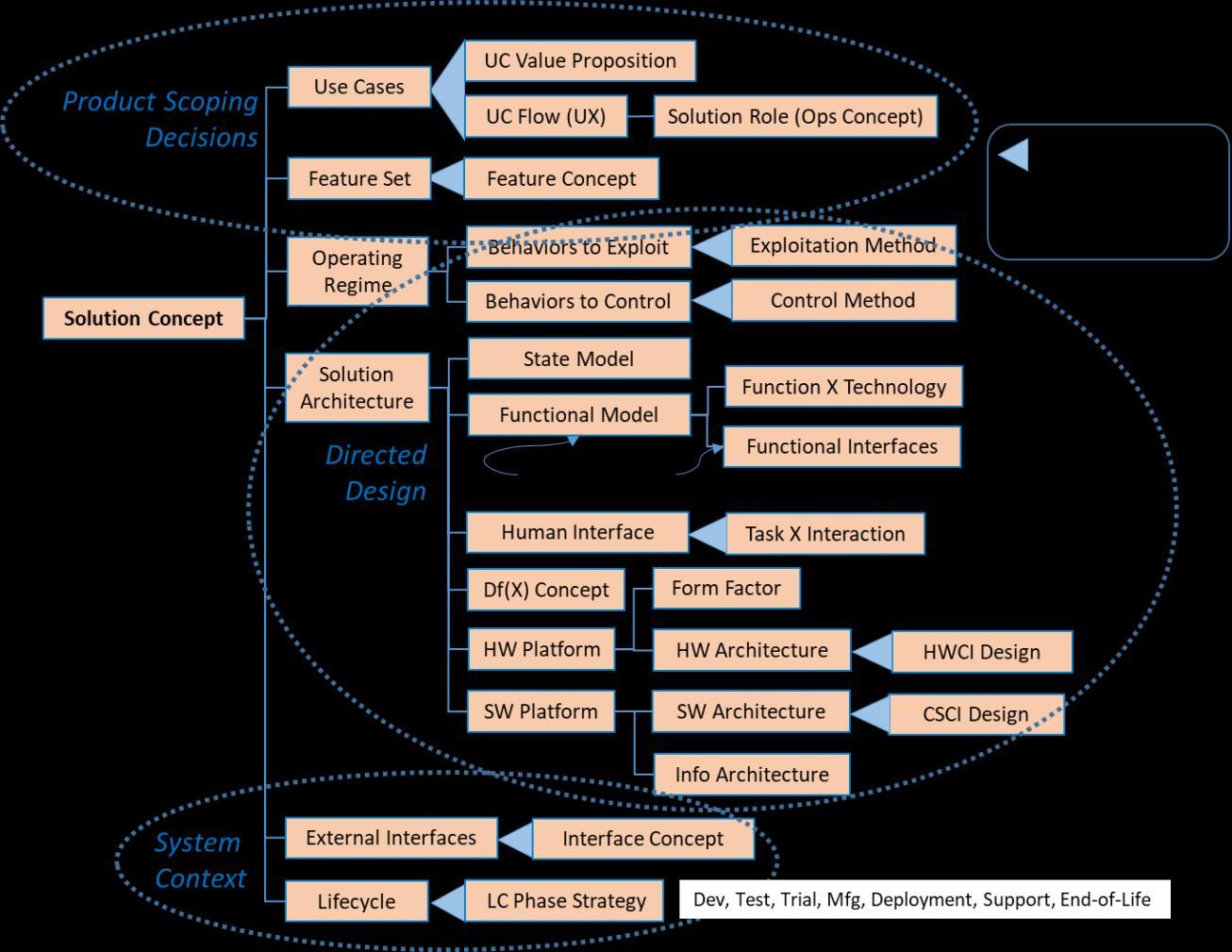
Figure 2 – System/Product Design Decision Pattern The technique used when reverse engineering is a bit like mining for precious metals or gems. The requirements analyst reads carefully through the originating requirements or other documents that describe the mission or business context, looking for noun phrases, e.g., adjective-adjective-noun, that represent directed solutions within the requirements. For each directed solution, ask “If <DirectedSolutionX> is the answer, what was the question?” where the questions represent an instance of a decision within one of the relevant decision patterns.
Decision Name Decision Description
1 Solution Concept What is the top-level concept for this system or solution? What makes it unique?
1.1 Use Cases to Support What use cases (scenarios, missions) will this solution support?
1.1.1 Value Proposition How will the solution deliver value to the end users and customers of this use case? (For each use case chosen in 1.1)
1.1.2 Use Case Flow How will this use case be performed? What flow of activities and events will occur? (For each use case chosen in 1.1) Alternative(s)
Decision Name Decision Description
1.1.2.1 System Role What role with the system play in this use case? What capabilities and value will it deliver? (For each use case chosen in 1.1)
1.2 Feature Set What are the primary features or groups of features that will be delivered? Alternative(s)
1.2.1 Feature Concept How will this feature be implemented (technology, top-level design)? (For each feature chosen in 1.2)
Table 1 – Product Scoping Decisions For example, I recall the specification for a combat vehicle that included a requirement for a “twobottle halon system” on-board for fire suppression. It was obvious from the context and a limited knowledge of technology, that the directed solution answered the question (aka decision): Choose Fire Suppression Solution Concept which is an instance of the more general decision: Choose FunctionX Technology as shown in Figure 2 (at level 4 in the middle-right section). That led to requirement issues to be addressed with the stakeholders as to:
• Why halon? (the directed technology alternative) • Why 2-bottle? (the directed solution architecture) The directed solution turned out to be a fleet-wide preference to reduce the logistics footprint. In this case the directed solution was validated as a requirement for this vehicle. Often (and thankfully so) the requirements will not direct solution technologies or physical architectures, but implicit technology choices may be inferred from the way the requirements are stated. A requirement worded as “the vehicle shall have a range of 500 kilometers (under certain load and driving conditions) between recharging cycles” likely implies that the stakeholders are looking for a vehicle with an electric propulsion system and some type of battery as the energy storage method. Such assumptions concerning stakeholder intent would be captured as hypotheses (implied solution alternatives) in the Decision Blitz as shown in Table 2:
Decision Name Decision Description Implied Solution Alternative Derived Requirement
Choose Propulsion System Concept What technology, method or solution concept will be used to deliver the Propel the Vehicle function? Electric propulsion system Range between recharging
Choose Energy Storage Technology What technology, method or solution concept will be used to deliver the Store Energy function? Battery (chemistry TBD) Range between recharging
Table 2 – Decision Blitz Example with Implied Solutions (Hypotheses)
Note that there is nothing in the requirement that demands a particular battery technology. That would be an open question (requirement issue) to address with the stakeholders during the face-toface portion of the Decision Blitz. The requirements analyst is intentionally taking the viewpoint of the stakeholder in this process, replaying in abbreviated form the stakeholder choices that have shaped their implicit idea of a solution, as expressed in system requirements. In a more complete example, the analyst would capture an alternative description to better clarify the directed or implied solutions. These natural language solution descriptions may also be augmented by physical architecture models (components and interfaces) and logical architecture models (functions with control flow and item flow) to clarify the implied solution concepts. Any of the design decisions in Figure 2 may be made by the system stakeholders and communicated to solution developers as system requirements. However, those shown in the middle oval labeled “Directed Design” take away significant design freedom from the solution developer.
The top-level External Interface decision (shown in the System Context oval in Figure 2) is often made by the stakeholders, but incompletely delivered to the solution developers in the originating requirements handoff. Exploring this decision will often uncover external interfaces that have been overlooked or open decisions concerning how a specific interface should be implemented. The Lifecycle branch of the decision model (also in the System Context oval in Figure 2) is a top-level view of the design decisions associated with the enabling systems (development, verification, manufacturing, deployment, support and end-of-life) required by the System of Interest. Ideally these enabling systems will be concurrently engineered along with the System of Interest; their design decisions must align with the System of Interest design decisions. However, at the point of the Decision Blitz choosing a top-level strategy for each enabling system may suffice as a source of requirements that will be levied on the System of Interest. After completing a pass through the originating requirements and source documents, the analyst walks through the resulting decision table to identify decisions in the pattern from which no directed or assumed solution can be inferred. If the full decision pattern is relevant to the problem domain, this “white space” may represent gaps in the stakeholders thinking and therefore gaps in the system requirements.
Step 2: Validate and Refine Stakeholder Decision Model
Regardless of the process skills or problem and solution domain knowledge of the requirements analyst, the reverse engineering exercise at the start of the Decision Blitz can only yield a set of hypotheses of what is in the heads of the stakeholders and “behind” the originating requirements. However, these hypotheses are more focused than a few guesses or questions triggered by reading a specification. They reflect fundamental questions that must be answered to define the role of any system or product in the larger world and reasonable inferences that can be drawn from what the stakeholders have provided as requirements. Validating these hypotheses is accomplished by walking through the decision model with the stakeholders, ideally assembled together, and asking for confirmation or clarification of each hypothesis (implied solution alternative and its validity as a source of the stated requirement). In the simple case, a stakeholder will confirm the implied solution alternative, add some refinements to the alternative description and explain the rationale for why this solution leads to the system requirement. But be prepared for fireworks at this point – it is quite common for stakeholders to disagree with one another over the implied alternative and get into heated debates over how “that” idea became
enshrined in the requirements. In such cases, the requirements analyst captures additional alternatives advocated by the stakeholders and marks the decision with Status = Open. Decisions in the pattern for which there are no implied stakeholder answers also are statused as Open. It must be determined later whether these decisions are considered by the stakeholders as “in-scope” for the development project. If the decision pattern is well-adapted to the problem domain, it is likely that either the stakeholders need to make additional decisions before releasing the final specification or they need to fund the solution provider to perform that analysis on their behalf. Proceeding without a plan to nail down these decisions is a recipe for project failure. Ultimately the face-to-face portion of a Decision Blitz is about gaining stakeholder consensus on their higher-level decisions and then flowing down the consequences of those decisions into the system requirements baseline. Although a tabular view of the decision model may be sufficient, I have found that providing a graphical visualization of their decisions is an important communication tool to foster stakeholder engagement. As shown in Figure 3, an initial DBS for the project is depicted as a hierarchy with each decision represented as a two-panel box. The top panel includes the decision name (and often the decision number, i.e. its place in the hierarchy). The bottom panel includes the directed or implied solution alternative(s) that have emerged from reverse engineering or perhaps has been refined through the Decision Blitz process.

Figure 3: Decision Breakdown Structure – 2-panel format
A variety of MBSE tools, drawing tools or Microsoft Excel may be adapted to generate such diagrams.
Step 3: Derive/Trace System Requirements from Stakeholder Decisions
At this point in the process, the requirements analyst has gained a reasonable level of stakeholder consensus by making explicit the stakeholders’ implicit decisions that created the requirements. The tabular view of the DBS (or more likely the database that drives that view) will have captured the requirements derivation trace from the solution alternatives to the draft system requirements. This is the time to further exploit the investment made in reverse engineering the decision model. It is highly likely that additional (missing) requirements may be derived from the solution alternatives.
To uncover these requirements, repetitively ask for each “Closed” decision “What additional requirements does the solution chosen impose on the rest of the system?” If you have detailed and precise descriptions of the alternatives, elaborated by physical and logical models of the alternative’s structure and behavior, it will help you more efficiently think through the derived requirement consequences associated with each choice. Over the years, I have found a simple heuristic helpful in identifying derived requirements that leads to refining the question stated above to focus on different aspects of the chosen alternative.
“How does the chosen alternative’s Structure, Behavior, Footprint, Interfaces and Lifecycle impose constraints on the rest of the system?’
The process of uncovering missing derived requirements takes both process skills and domain expertise, particularly knowledge concerning solution technologies. The same individuals who have helped refine the alternative descriptions and models will be invaluable at this point.
Step 4: Complete System Requirement Analysis
The decision model and decision-to-requirement trace created in Steps 1-3 provide a launchpad for performing a variety of additional requirements analysis techniques that may be part of a System Requirements Analysis process.
Context Analysis The alternatives identified for the External Interfaces decision should mirror the external systems and human actors that appear on a system Context Diagram. The Interface Concept decision for each external system/actor should further elaborate the physical implementation of each interface, i.e. how the items that flow across the interface will be transferred.
Design Requirements Analysis The reverse engineering process should uncover a majority of the cases where the stakeholders have directly specified or indirectly implied the internals of the solution design, rather than specifying the solution-independent characteristics of the desired system. Both methods use the same technique, i.e., reading the originating requirements looking for nouns or adjective-noun phrases that represent prescribed elements of the system.
States & Modes Analysis Few stakeholders fully specify system states and modes as requirements. Decisions concerning highlevel system behavior, e.g., use case variants may help uncover potential system states. The Feature Set decision may also hint toward groupings of functionality that have distinguishable business value and that may be the building blocks of system modes.
Functional Analysis The functions of a system are derived from the system use cases, use case flow alternatives and system-assigned steps in the use case flows. Any work during the Decision Blitz that models the use case flows as a sequence of system and operator steps is a good starting point for performing more rigorous functional analysis during the remainder of the system requirements analysis (SRA) phase.
Rest of Scenario Analysis Rest of Scenario Analysis explores more deeply the conditions under which use cases and associated system functions are performed. Identification of use case alternatives and variants will distinguish different situations in which the System of Interest is employed. A complete description of each use case alternative should include identification of environmental or contextual conditions.
Stakeholder Value Analysis Although the process of reverse engineering starts with originating requirements, stakeholder goals (Measures of Effectiveness) that reflect the value of margin beyond a requirement threshold will likely be clarified in the same process.
ERA Analysis The process of Entity-Relationship-Attribute (ERA) Analysis is encapsulated in the Information Architecture decision in which information classes, the relationships between classes and the attributes appropriate for each class will be chosen. Entity Relationship Diagrams (ERDs) or SysML/UML Class Diagrams represent information model alternatives.
OCD Development Performed across the total set of use cases, the Use Cases to Support, Use Case Flow and System Role decisions populate much of the content of the Operational Concept Description for the product and are a primary source of system functional and performance requirements.
System Requirements Review Requirements, both modified and newly discovered through the Decision Blitz and subsequent requirements analysis processes, should go through standard processes for validation, approval and traceability. A System Requirements Review (SRR) should be conducted to catch and resolve loose ends and gain approval for setting a system requirements (problem definition) baseline. Because of the heavy and direct involvement of stakeholders, the Decision Blitz can be viewed as a preliminary SRR.
Step 5: Plan Project Design Decisions
The initial version of the DBS draws a clear line between decisions made by the stakeholders (the source of system requirements) and those to-be-made by the solution developers. This gives the stakeholders and developers a chance to revisit the project work scope and to assess whether it can be accomplished at acceptable risk within the cost and schedule constraints. Figure 4 illustrates a typical DBS, split between stakeholder-owned and developer-assigned decisions.

Figure 4: Decision Ownership Split Between Stakeholders and Solution Developers
The investment to build a project decision model as part of system requirements analysis pays off not only through improved requirements. It sets up a decision planning and communication framework for the remainder of the project. The DBS provides a comprehensive Trade Study Plan that identifies for each decision the:
• decision owner who will lead the decision analysis. • decision authority who has the power to approve the recommended alternative. • cost and schedule budget for the decision analysis. • analytic methods used to inform the decision with objective data (models, simulations, prototypes, etc.). • analysis tasks to be performed and their assignments, budgets and schedules.
Conclusion
I have had the privilege a training a few thousand professionals on how to use decision patterns to perform the forward engineering of systems, products or processes. The process of reverse engineering stakeholder decisions for the sake of requirements analysis and validation depends on the same principles: • There is a decision pattern behind any strategy or design. • Decisions (through the alternative chosen) are the source of all requirements. • The Decision -> chooses -> Alternative -> results in -> Requirement traceability thread may be traversed in either direction.
• Elaborating alternatives in the form of detailed textual descriptions and physical and logical models is useful in understanding their derived requirements consequences. Reverse engineering against a decision pattern is more difficult than forward engineering from the decision pattern because: • Inferring an implied “upstream” solution alternative from a requirement is a less developed skill among engineers. • Mapping a stated or implied solution alternative back to a decision depends on a pattern matching skill that demands some level of internalization of the decision pattern. Such skill can be gained only through experience, i.e., multiple cycles of learning in use the decision pattern. As a first step in gaining these skills, I encourage our readers to practice reverse engineering solution alternatives against the product design decision pattern shown in Figure 2 using a 2-page marketing blurb or data sheet for any product or service as the starting point. PPI can help you apply the power of decision patterns to your engineering challenges. Look for further announcements concerning our decision-focused services. In the meantime, please inquire if you have near-term interest in a participating in a decision-focused reverse engineering engagement to help analyze and refine your system requirements. Contact the author at jfitch@ppi-int.com or PPISyEN@ppi-int.com to communicate your interest.
References
[1] Fitch, J.A. 2016. “Reverse engineering a decision and roadmap baseline”, https://decisiondriven.wordpress.com/2008/08/19/reverse-engineering-a-decision-and-roadmapbaseline/, 19 August. [2] Fitch, J.A. 2016. “Reverse engineer to go farther faster”, https://decisiondriven.wordpress.com/2016/09/14/reverse-engineer-to-go-fartherfaster/, 14
September. [3] Fitch, J.A. 2009. "Exploiting Decision-to-Requirements Traceability, briefing to NDIA CMMI
Conference, Denver, CO (US), 9 November, 2009. [4] Mendonza, P. and Fitch, J.A. 2012. “Decision Management (DM) as the engine for scalable, crossdomain Systems Engineering”. Paper presented at 22nd Annual International Symposium of the
International Council on Systems Engineering, Rome, Italy, 9-12 July. [5] Fitch, J.A. 2016. “Product Scoping Decisions”, https://decisiondriven.wordpress.com/2016/08/30/product-scoping-decisions/, 30 August.
About the Author
John Fitch is a Principal Consultant and Course Presenter for Project Performance International. John brings over four decades of systems engineering, engineering management, consulting and training experience to the PPI team. In 2012, John was certified by INCOSE as an Expert Systems Engineering Professional (ESEP). Within the field of systems engineering, John’s career has focused on decision management, requirements management, risk management, systems design & architecture, product/technology road-mapping and innovation. In addition to defense/aerospace, John has guided initiatives in domains such as communications systems, software, energy, nanotechnology, medical devices, manufacturing systems, knowledge management and business process improvement.
