
12 minute read
By Juan Navas


FEATURED ARTICLES
Architecture Models as Enablers of Agility
Architecture Models as Enablers of Agility
By Juan Navas
by Juan Navas, Thales Corporate Engineering
Email: juan.navas@thalesgroup.com
Copyright ©2021 by Juan Navas. All rights reserved. Authored for PPI SyEN.
Based on the paper Models as enablers of agility in complex systems engineering presented at the INCOSE International Symposium 2020 by Juan Navas, Stephane Bonnet, Guillaume Journaux and Jean-Luc Voirin.
Abstract
This series of articles follows the engineering teams of the PythaDrone project during their endeavor of developing a drone-based product that addresses multiple market segments. The focus is on the use of system architecture models as the basis for several technical, management and organizational activities, in a context in which a company implements agility in its engineering processes. Although the PythaDrone project and the Pythagoras company are fictive, the practices described here are those put in place in some of our projects and business units.
Episode 2 – Run!
Previously on Episode 1
In Episode 1 of this series of articles, we introduced the fictive PythaDrone team in the also fictive Pythagoras company. The PythaDrone team is in charge of developing a lightweight drone-based product that will address different markets: agriculture, aircraft exterior inspection, and public security enforcement. The team is implementing both agility and MBSE practices in order to react faster to changes in the customers’ expectations and ensure the consistency of the design.
We followed them through their initial “warm-up” activity, in which they built their engineering strategy and the first vision of their product. In this Episode 2 we will situate ourselves later in time, and we will focus on the Systems Architecture team while specifying a subset of the features to be developed in further iterations.
Defining the scope of design for Iteration 3
The Architecture team has been releasing incremental versions of the product architecture at each product-level iteration (i.e. every 3 months). The project started 6 months ago and the team is preparing the third iteration at the product-level. Until now the design has been focused on the visualization capabilities of the product in order to get feedback on user experience (UX) as soon as possible from operators. The table below summarizes the progress status of design, development and test per capability.
Capability
% designed % developed % validated
Manually pilot the drone 40% 20% 10% Automatically follow a flight plan 40% 20% 20% Manually acquire data 30% 10% 10% Automatically acquire data 60% 40% 40% Visualize data during mission execution 70% 70% 30% Visualize data after mission execution 100% 50% 40% Analyze data during mission execution 0% 0% 0% Analyze data after mission execution 50% 20% 0%
During the “warm-up” activity of this iteration 3, the team identifies which product capabilities would be designed in the next 3 months. They do so by analyzing the product delivery milestones and the availability of resources to develop them, among other factors (cf. Episode 1 for details on how to run a “warm-up” of an iteration). The conclusions of the warm-up are: • The team will focus on the Manually pilot the drone and Manually acquire data capabilities, which design has already started but needs to be completed soon in order to provide a first prototype to future customers
• The team will also have to update the design of the Visualize data after mission execution, which design was thought to be complete, but will need to be modified following the feedbacks from the
UX specialists • For the other capabilities, the software and tests teams already have enough to do with the past releases of the design Now the team is ready to start the “Run” activity of the iteration.
Run
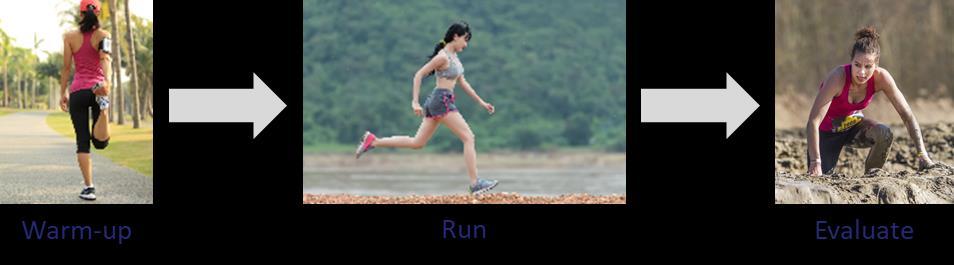
“Run” is another kind of activity that you perform in an iteration, along with “Warm-up” and “Evaluation”, as presented in the previous episode. Using the sports analogy, in an iteration you need to prepare yourself (warm-up) before performing a continuous and strong effort (run), and if you want to improve you need to measure and analyze your performance (evaluate).
For an engineering team, the “Run” activity is made of shorter iterations or sprints, aiming at implementing product features. This includes (non-exhaustive list) the detailed definition of product functions, the development of the system and subsystems' architecture; the development of the software and hardware implementing expected behavior; and the verification and validation of what will be delivered to the customer.
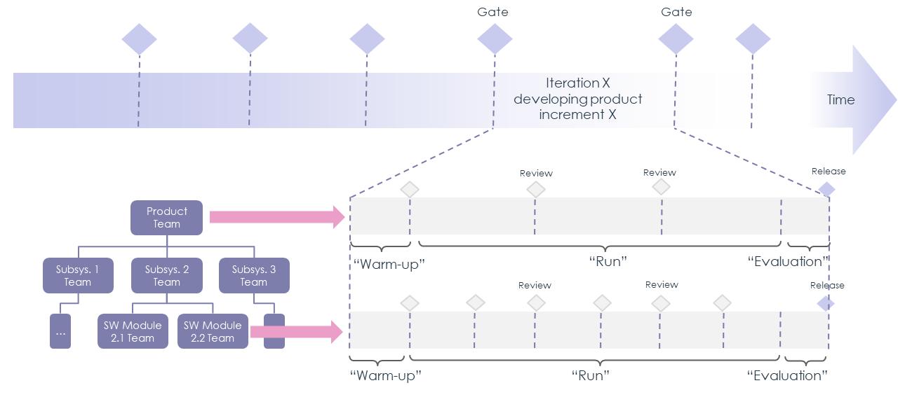
Sprints tend to have the same period, but their number inside an iteration may vary according to the life cycle of the project and the organization. For instance, teams devoted to product components may do 6 beats inside a 3-month iteration (one each 2 weeks), whereas product-level architecture teams may do 3 (one per month), as illustrated in the figure below.
Designing product capabilities
The MBSE approach that the Pythagoras company implements is based on three pillars: a set of concepts that are known and understood by the engineers in the company, a method for performing MBSE, and engineering tools that are consistent with the method. The concepts and methods are based on the Arcadia method [VOIRIN 2017], which has been slightly adapted to match the vocabulary of the company; the MBSE tool is the open source tool Capella.
Designing product capabilities with Arcadia and Capella MBSE
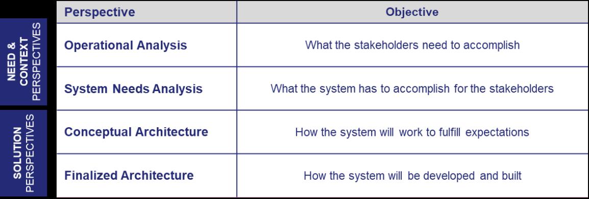
Arcadia is a model-based architecture method devoted to systems, software and hardware engineering. It allows architects to capture the needs of the stakeholders (customers, users, relevant regulations …), define and share the product architecture with all engineering stakeholders, validate the design early and justify it. Arcadia has been proven especially effective when designing products with strong constraints to be reconciled such as cost, performance, safety, security, reuse, consumption, weigh, etc. It has been applied in a large variety of contexts over the last ten years. Arcadia defines a set of perspectives, in accordance with the [IEEE 1220] standard. A perspective is a way of analyzing the product. The method encourages the architect to adopt different perspectives and to run engineering tasks for each of them. Arcadia proposes four main perspectives: two of them aim at reaching a shared comprehension of the context in which the product will evolve and the needs that it shall satisfy (Operational Analysis and Systems Needs Analysis), the two others aim at defining the architecture design, both at conceptual and physical levels.
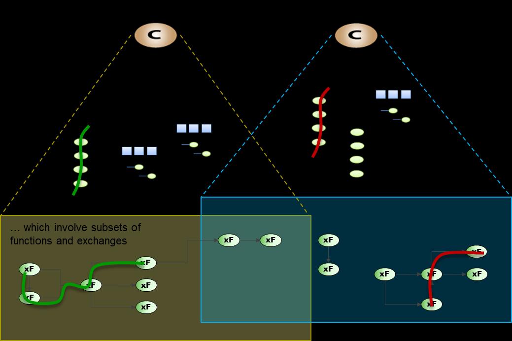
One of the main concepts in Arcadia is the Capability, which represents the ability of the product to provide a service that will support the satisfaction of the stakeholders’ expectations. As an illustration, the PythaDrone product, through offering the service of manual piloting, will support a farmer at surveying his agricultural field. Capabilities are user-oriented, and hence they are a good vehicle for discussing the product with the customers. However, the service represented by a Capability usually needs to be provided in different ways depending on the usage contexts of the product. Arcadia defines two concepts that describe Capabilities in different usage contexts: Functional Chains and Scenarios. They both describe how the product, the product’s components and/or the entities external to the system shall be involved in providing a service. Scenarios are specific in that they can describe dynamic, time-related interactions, whereas Functional Chains do not. Functions represent what the product, product components and external entities are expected to do. Functional Exchanges represent the dependencies between Functions. Both are involved in different ways in different usage contexts (Functional Chains and Scenarios). In addition, a Function can contribute to more than one Capability, i.e. it can be involved in different usage contexts of different Capabilities. To refine Functions and Functional Exchanges, textual requirements are associated to them: textual requirements and model requirements complement each other, as presented in [BONNET, 2019]. The Figure below summarizes the relationship between Capabilities, Functional Chains and Scenarios, and Functions and Functional Exchanges.
We will take a closer look to the Manually pilot the drone capability (from this point on, the name of model elements shown in the diagrams are written in grey). Drone piloting refers to controlling the motion and orientation of the drone. One of the variabilities being considered at this point is whether to offer the ability to automatically avoid obstacles during navigation. Marketing identified markets for which it would be an attractive feature (security), but also markets in which it would be a superfluous one. The Architecture team decides to design both and ensure that the feature can be removed if necessary.
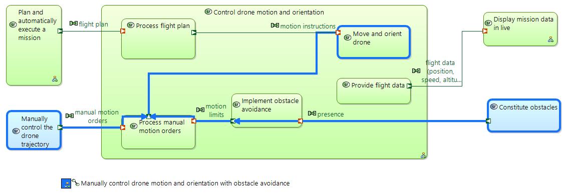
Let us zoom in on one of the Functional Chains of this capability: Manually control drone motion and orientation with obstacle avoidance. The Architecture team decides to work on the System Needs Analysis perspective to formalize the functions that the product as a whole shall perform in order to provide the capability. The dataflow below is one of the diagrams shared with other engineering teams, it shows: • Three major functions of the product: Plan and automatically execute a mission, Control drone motion and orientation, and Display mission data in live; shown in green • Two functions that have been allocated to external entities: Manually control the drone trajectory which has been allocated to the Operator, and Constitute obstacles, which merely represents the existence of external obstacles and may carry the expected characteristics of those; they are shown in blue
• The result of the functional analysis of the Control drone motion and orientation function, which has been decomposed in 5 sub functions • The dependencies between these functions • The functions and functional exchange that are involved in the functional chain Manually control drone motion and orientation with obstacle avoidance, which are either highlighted in blue or implicit by the fact that their input / output functional exchanges are involved in it.
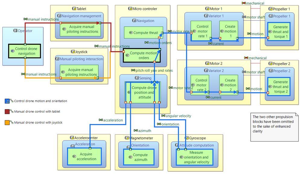
Functions have been further refined through textual requirements, not shown above. Functional Exchanges have been further described using other available concepts in Arcadia and Capella such as Exchange Items and Information models, not shown here neither. In previous iterations, the Architecture team had developed a reference architecture for the product, which slightly evolves at each iteration. One of the variabilities that have been already considered concerns the device that will be used by the operator to control the motion of the drone. Some markets require fine control of the motion (security and inspection markets) whereas others do not (agriculture). The first ones will be provided a dedicated joystick, and the second ones will control the motion using a tactile tablet, which is also used for visualization purposes. Because of these architectural decisions, when Architects work in the Physical Architecture perspective, they will need to define several variants of the functional chains describing the Manually pilot the drone capability. The figure below is one of the diagrams that will be presented to software development and tests teams as a specification of what is expected from them in the next iterations. It shows:
• The physical components of the architecture involved in this capability: Tablet, Joystick,
Microcontroller, Accelerometer, Gyroscope, Magnetometer, and Motors and Propellers; shown in yellow • The expected behavior of these physical components, which is represented by the functions (in green), grouped in behavioral components (in blue) that are deployed in the physical components • The Operator external entity (in light blue) and its function related to the capability • Three of the Functional Chains that realize the capability in the Physical Architecture perspective:
Control drone motion and orientation, Manual drone control with tablet, and Manual drone control with joystick; highlighted in blue. The functions highlighted in black are involved in more than one functional chain. The end-to-end service is represented by the composition of functional chains: the joystick variant is represented by the Manual drone control with joystick + Control drone motion and orientation functional chains, the tablet variant is represented by Manual drone control with tablet + Control drone motion and orientation functional chains.
In fact, as the automated piloting of the drone was already addressed in previous iterations, the functional chain Control drone motion and orientation was already been developed and tested. The iteration hence focused on designing the upstream functional chains.
Were the architects working alone?
Of course not! Co-engineering is a well-established practice in Pythagoras. Focusing only on the teams considered in this series of articles:
• Integration, Verification and Validation (IVV) representatives worked with Capability Leaders and
Architecture team to secure the testability of product-level functional chains. In fact, in parallel they translated Functional Chains in System Needs Analysis perspective in corresponding productlevel test procedures. Each test “tells the story” of its corresponding functional chain.
• Representative members of the software teams participated to the regular reviews of the architecture increments. Their role was to anticipate the feasibility and to make sure the productlevel vision of the solution is compatible with the current software architecture.
Next episode
In the third and last episode of this series of articles, we will see what happens at the end of this iteration and how the architecture increment is delivered to other engineering teams. We will also take a closer look at the activities performed by IVV and software team in further iterations, and to the “Evaluation” activity.
List of Acronyms Used in this Paper Acronym Explanation
MBSE Model Based Systems Engineering PLE Product Line Engineering
References
Dove, Schnidel 2018. Agile Systems Engineering Life Cycle Model for Mixed Discipline Engineering. 28th Annual INCOSE International Symposium 2018. INCOSE, 2014, ‘A World in Motion – Systems Engineering Vision 2015’. ISO/IEC/IEEE 15288, 2015, ‘Systems and software engineering – System life cycle processes’. IEEE 1220, 2005, IEEE Standard for Application and Management of the SE Process Voirin J-L, 2017, ‘Model-based System and Architecture Engineering with the Arcadia Method’, ISTE Press, London & Elsevier, Oxford, 2017 Capella, 2019, Capella Polarsys Website: https://www.polarsys.org/capella/ Bonnet S, Voirin J-L, Normand V , Exertier D, 2015, ‘Implementing the MBSE Cultural Change: Organization, Coaching and Lessons Learned’, 25th INCOSE International Symposium Navas, J, 2019, ‘How MBSE practices support the effective implementation of a Product Line Engineering approach’, 29th Annual INCOSE International Symposium, 2019. Bonnet S, Voirin J-L, Navas J., 2019, ‘Augmenting requirements with models to improve the articulation between system engineering levels and optimize V&V practices’, 29th Annual INCOSE International Symposium, 2019. ISO/IEC TR 24748-1, 2010, 'Systems and software engineering — Life cycle management — Part 1: Guide for life cycle management'
About the Author
Juan Navas is a Systems Architect with 15 years’ experience on performing Systems Engineering activities and implementing innovative engineering practices in multiple organizations. He currently leads the Modelling & Simulation team at Thales Corporate Engineering and dedicates most of his time to expertise and consulting for Thales business units and other organizations worldwide, accompanying managers and architects when implementing MBSE practices. He holds a PhD on embedded software engineering, a MSc Degree on control and computer science, and Electronics and Electrical Engineering Degree.


