Weather Monitoring Station
How do weather sensors work?
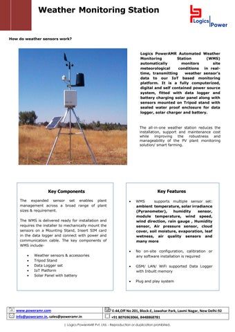
Logics PowerAMR Automated Weather Monitoring Station (WMS) automatically monitors site meteorological conditions in realtime, transmitting weather sensor’s data to our IoT based monitoring platform. It is a fully computerized, digital and self contained power source system, fitted with data logger and battery charging solar panel along with sensors mounted on Tripod stand with sealed water proof enclosure for data logger, solar charger and battery.
The all-in-one weather station reduces the installation, support and maintenance cost while improving the robustness and manageability of the PV plant monitoring solution/ smart farming.
Key Features
Key Components The expanded sensor set enables plant management across a broad range of plant sizes & requirement.
WMS supports multiple sensor set: ambient temperature, solar irradiance (Pyranometer), humidity sensor, module temperature, wind speed, wind direction, rain gauge , Humidity sensor, Air pressure sensor, cloud cover, soil moisture, evaporation, leaf wetness, air quality sensors and many more
No on-site configuration, calibration or any software installation is required
GSM/ LAN/ WiFi supported Data Logger with Inbuilt memory
Plug and play system
The WMS is delivered ready for installation and requires the installer to mechanically mount the sensors on a Mounting Stand, Insert SIM card in the data logger and connect with power and communication cable. The key components of WMS include
Weather sensors & accessories Tripod Stand Data Logger set IoT Platform Solar Panel with battery
www.poweramr.com
E-44,Off No 201, Block-E, Jawahar Park, Laxmi Nagar, New Delhi-92
info@poweramr.in, sales@poweramr.in
+91 8076963066, 8448868781
| Logics PowerAMR Pvt. Ltd. - Reproduction or duplication prohibited.
System Architecture Other sensors
Modbus Converter
3 pin Socket 230v AC Supply
Wind speed sensor
Wind Direction Sensor
Ambient Temp. Sensor SMPS Data Logger Module Temp. Sensor
Pyranometer
Power cable 2 Core RS485 Cable 3 Core RS485 cable
Connection Diagram of WMS and Data Logger
| Logics PowerAMR Pvt. Ltd. - Reproduction or duplication prohibited.
Technical Specifications Technical data and types Sensors Ambient temperature
Range: 0°C to 100°C, Accuracy +/- 0.5°C
PV panel temperature
Range: 0°C to 100°C, Accuracy +/- 0.5°C
Solar Radiation sensor
Range 0 to 1800 W/m2 Accuracy +/- 5% Temperature Range -40°C to 65°C
Wind Speed Sensor
Range 0 to 250km/h (0 to 69m/s) Sensor Type: Three Cup Accuracy +/- 3% Start wind Speed 0.5m / s Temperature range -40°C to 65°C
Wind Direction Sensor
Range 0-360 degrees Accuracy +/-3% Temperature range -40°C to 65°C Sensor Type: Wind vane potentiometer Type
WMS DATA LOGGER SPECIFICATIONS Communication Serial port
RS-485 2 wire, Modbus RTU,
Recommended cable
Cat. 6/ RS485/ or equivalent
Power supply DC power supply input Supply Current
8-32 VDC 0.08A at 12 VDC
Compliance Humidity Enclosure
0 to 100% Condensing IP 65
Physical parameters Dimensions Weight Operating Temperature
105mmx95mmx24mm 160gm -10°C to 55°C
Mounting Stand Material Type Stand Type Height
MS, Power coated Tripod 8 feet
Warranty Standard warranty
1 year
WMS IoT Platform | Logics PowerAMR Pvt. Ltd. - Reproduction or duplication prohibited.
WMS Dashboard
Irradiation Curves
Intelligent Analysis & Multiple graphs comparison | Logics PowerAMR Pvt. Ltd. - Reproduction or duplication prohibited.
Sensors Installation
Sola r
Solar Radiation Sensor/ Pyranometer Pyranometer is to be mounted in an easy-to-reach location in order to clean the dome regularly and carry out maintenance. At the same time, make sure that no buildings, constructions, trees or obstructions exceed the horizontal plane where the pyranometer lies. If this is not possible, select a site where obstructions in the path of the sun from sunrise to sunset do not exceed 5 degrees of elevation. N.B The presence of obstructions on the horizon line affects significantly the measurement of direct irradiance Pyranometer is to be located far from any kind of obstruction, which might reflect sunlight (or sun shadow) onto the pyranometer itself. The sunlight sensor must be installed at the same azimuth and tilt angle than the PV array.
Mounting
Using the bubble level on the sensor as a guide, adjust the sensor until it is level by tightening or loosening the screws. The top of the Solar Radiation sensor should be even with or slightly above the rim of the rain cone. The entire comb structure of the UV Radiation sensor should be above the rim of the rain cone
Final leveling of the sensor(s) should be done with the ISS mounted in its operating location
Ensure that the cables are free of crimps. Secure them to the support tubes with the provided cable ties so that they will not fray in the wind.
Shade the sensor and make sure the reading changes
| Logics PowerAMR Pvt. Ltd. - Reproduction or duplication prohibited.
Ambient Temperature sensor The Ambient Temperature Sensor comes factory-assembled inside the radiation shield. The radiation shield bracket can be mounted to a pipe (1.0 - 2.0 in. diameter), using the supplied U-bolt. The radiation shield can be installed anywhere in the vicinity of the PV array. It is recommended to place the Ambient Temperature Sensor on the north side (in the northern hemisphere) of the array, otherwise you must provide array shading setback
Mounting • The Solar Radiation Shield may be mounted in three orientations. • On the side of a wooden post or a wall. • On a metal pipe with outside diameter between 1 in. and 1-1/4 in. (25 mm and 31 mm) On top of a wood post.
| Logics PowerAMR Pvt. Ltd. - Reproduction or duplication prohibited.
Module Temperature Sensor This sensor is designed to attach directly to any solar panel. When placed on the center back side of the panel, it accurately measures the temperature of the panel. Prior to installation of the PV temperature sensor onto the PV panel, the installation area of the panel back should be thoroughly cleaned. This cleaning will ensure a good bond between sensor and panel and allow for accurate panel temperature readings. After cleaning, peel off the protective adhesive tape on the temperature sensor and stick it onto the back of the panel. Firmly press the sensor into place.
Mounting
Select a PV module that remains non-shaded throughout the day. Peel the backing from the adhesive tape and press the sensor firmly against the surface. Do not attempt to extend or shorten the pre-assembled 2.5 m cable. The module temperature sensor is affixed to the back of the PV module. Tie the sensor cable off in a way that does not pull on the sensor It is recommended to fix the sensor and the cable with an additional adhesive tape.
| Logics PowerAMR Pvt. Ltd. - Reproduction or duplication prohibited.
Wind Speed Sensor The wind speed sensor comes in three different parts. We have the sensor body, the anemometer cup wheel and an Allen key to mount the cup wheel on the sensor body. There are different ways to mount the sensor. When selecting your mounting system, take into consideration that you will occasionally need to access the anemometer for preventive maintenance and possible component replacement. The goal of installing a wind speed meter (anemometer) is to position it in a location where the wind flows freely and is not influenced by nearby objects. For the most accurate wind speed readings, mount the sensor as the highest object for 50 feet in all directions.
Mounting
Cups should be on the top of the sensor. Mount vertically.
Wind Direction Sensor The goal of installing a wind direction meter is to position it in a location where the wind flows freely and is not influenced by nearby objects. For the most accurate readings, mount the sensor as the highest object for 50 feet in all directions.
Mounting
Allow sufficient clearance for the wind sensor. Install the wind sensor away from buildings or any other objects that might affect the airflow Try to make the sensors the highest object around. 7 feet or more above the surrounding obstructions is best The sensor must be mounted in an upright position; otherwise, water can enter the sensor and destroy it
| Logics PowerAMR Pvt. Ltd. - Reproduction or duplication prohibited.
Tools and Materials Needed
Wrench or pliers Wire cutters and stripper Multimeter Drill with 3/16 in drill bit (4.7 mm) to drill pilot holes Adjustable wrench or 11/32 in. wrench and 7/16 in Electrical Tapes to cover the wire
We pursue a policy of continuous research and product development, Specifications and features are subject to change without notice
Logics PowerAMR Pvt Ltd
www. poweramr.in
Contact +91 8076963066
| Logics PowerAMR Pvt. Ltd. - Reproduction or duplication prohibited.