13 minute read
Case Study Building : Phase I Assignment

from PJR Portfolio
by pjrmaya

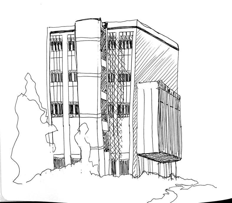
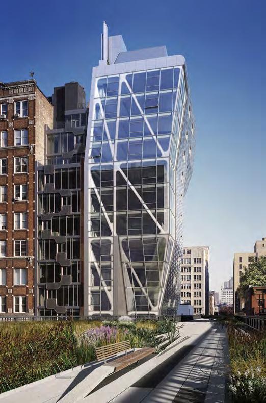
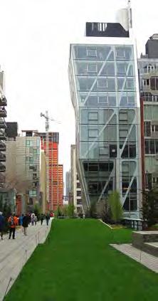
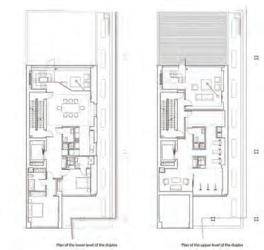
In New York’s West Chelsea neighborhood, Neil Denari’s HL23, located at 515 West 23rd Street, nudges itself center court onto the converted rail line park known as the High Line. Finished in 2011, HL23 marked Denari’s first go at a freestanding building. High Line 23 LLC, under the care of developer, Alf Naman, hired the former Director of the Southern California Institute of Architecture (SCI-Arc) and renowned Los Angeles Principal of NMDA, for his use of advanced technology to shift, bend, fold, and unfold structures in unconventional yet beautiful geometry. On a forty by ninety-nine-foot lot, Denari maximizes the real estate opportunity and provides Chelsea one of its first luxury condominium buildings. The reverse tapered fourteen-story, 39,200 squarefeet tower narrows on the third floor and gradually bulges to its maximium width on the fourteenth floor. “To capture the most floor area possible, they adjusted the silhouette of the building to contract and expand according to the site constraints and zoning regulations.”1 The tower holds eleven residences that range from 1,900-3,600 square-feet and cost between $2.65M to $15.5M each. It enjoys south oriented views of the Husdon River and peaks of the High Line towards the east in its living spaces. On the ground level, a commercial space, currently used as a gallery, supports a section of the High Line on its roof. Its westward neighbor is Highline 519 designed by Linda Roy. Made of a steel superstructure, concrete substructure, and a curtain wall of glass and embossed stainless steel megapanels, HL23 defines itself as a sculptural piece of architecture within the arts community of Chelsea. The building’s components were manufactured offsite enabling its complexity to erect from a complicated and challenging site.
Advertisement
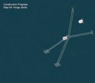
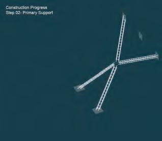
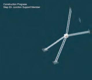
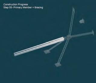
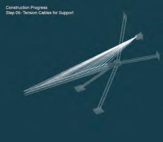
Sitting on a small floor plate, HL23 is bounded by the elevated structure of the High Line and an adjacent building to the north. The unique site restrictions in combination with strict zoning regulations of New York City (NYC) require unique design solutions that give residents an unprecedented living experience. The first of those experiences is an uninterrupted floor plate. Structural members are pushed to the perimeter leaving a column free living space. Adding to the difficulties of a column free floor plate, the design of HL23 calls for a cantilevered portion that extends over the High Line on the upper floors. In order to achieve this the structural team proposed diagonally braced steel columns at the perimeter of the building that are tied back to a moment frame running along a parti wall on the West side of the building. Together these hold the structure in net tension under gravity loading.
Lateral forces of the building are resisted using a steel plate shear wall (SPSW). SPSW are not typically used in NYC but were efficient and cost-effective given site restrictions. A main component of SPSW are shear plates that attach inside a steel frame to prevent lateral forces. These are hidden inside the walls that surround the building core, stairs, elevator, and mechanical shafts. In addition to the efficiency and cost, using plates in leu of typical crossed braced wide-flanges, property owners gain an extra few feet of usable squarefootage. The SPSW system was one of the prefabricated components, brought to the site in modular sections where they were raised, spliced, and welded into place.
At the base, the building is lowered seven feet below grade and sits on a three-foot concrete foundation. Around the perimeter of the foundation are soldier piles spaced six-feet apart that are driven fifteen-feet into sand below. A one-foot-thick concrete retaining wall encloses a cellar that houses all service rooms and resident storage. To pour the retaining wall along the existing partiwall to the west, underpinning was required to stabilize the adjacent buildings grade beam.
General Description
In that same fashion the team of architects and engineers developed a thoughtful approach to the exterior envelope. The south facade is constructed of curtain wall units that are ganged together into megapanels which also were delivered to the site, hoisted into position, and attached to the primary structure. Spread beams tracing the perimeter of the building, just outboard of the columns and floor beams, act as the supports from which the megapanels are hung. These spread beams are laterally braced back to the edge of each floor plate through slotted angles that allow for deflection between floors. An embedded clip, referenced in the drawings as halfen anchor channels, receives these slotted angles. The structural drawings will reveal how frequently the connections are occurring and with what precision. Discrepancies between the construction set drawings and actual construction photographs produce speculation of the direction the curtain wall manufacturers took with the actual installation.
Construction photographs indicate that there are specially designed embed plates poured concurrently with the floor slabs and that the spread beam is designed into the curtain wall megapanel with locations for a crane to raise the panel. The spread beam is designed with milled connection points that slide into the embed plates along the floor slab. These embed plates align to each panel end to accept the mega panel connection points.
Building Structure (Foundation & Superstructure)
The south elevation facing West 23rd Street is a spandrel free curtain wall. Its silhouette exemplifies the reverse tapered tower approach that cantilevers over the High Line’s elevated rail bed. The tower soars to a height of 176 feet. The second floor has an elevation mark of 11’-7”, floors two and three are separated by ten feet, floors four through eleven differentiate by eleven feet, and the penthouse duplexes on the twelfth and thirteenth floor span 11’-8 ¼” and 13’-6¾” respectively. In elevation, the southern façade width varies, being most narrow on the third floor at a 30’3¼” and widest on the fourteenth floor at 46’-5” extending beyond the property line due to a special zoning permit.
The superstructure’s steel zebroid-bracing runs the height of fourteen floors and is visible through the curtain wall which traces the structure with a ceramic frit pattern. The south façade contains the largest mega panels ever used in residential high-rise construction. The megapanels are made of double-glazed fritted glass and run six feet in width and over eleven feet in height. They connect directly to the superstructure leaving a clean exterior façade.
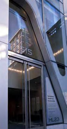
The entirety of the building sits on a grade of land that slopes seven inches upward toward the northwest. The façade serves as the main entrance of both the residential and commercial section of the structure. At the ground level, the design team has chosen a precast concrete base to give the allusion of a uniform ground line despite the change in grade.
In between the entrances to the residence and commercial space, the service entrance/ emergency exit is located. A wall hydrant gas vent lies behind a stainless-steel door panel. Exposed and not covered by the panel is the Siamese. Above the panel is a louvered door to cover the gas regulator vent with a one-inch diameter. An intercom is placed on the return panel to the left of that louvered door. On the intercom is a camera at the height of 5’-2 7/8 from the ground, a loudspeaker, digital display, and call button. Above the commercial space, in between the second and third floors, the structure begins to set back behind a parapet that provides a pigeon net.
There are twenty-four operable windows on the south elevation, two on each floor beginning at the second floor. Sixteen intermittent stabilization anchors (I.S.A) are located across the curtain wall. The twelve ISAs closest to the ground floor are placed in front of the top structural steel beam of each of the zebroid bracing systems. The ISAs are used for window washer to scale the elevation without damaging the façade with platforms banging against the glass.
Building Enclosure: Elevation

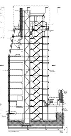
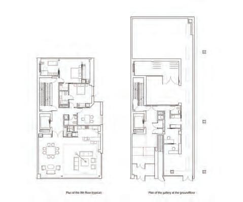
A section cut through HL23 reveals a clear understanding of the unique relationship of HL23 to the High Line, a corner stone of NYC lifestyle running 3 miles from 14th street to 34th street through the southern viaduct system of the abandoned Ney York Central Railroad. The structure even shares part of the original railroad that supports the roof of the retail. The following description focuses on the highlighted areas. (right)
On the ground floor a two-story lobby welcomes tenants’ home. The entrance to the lobby becomes a portico, set back 1’-2” from the face of the building. The setback defines this area as the entrance. The top of the portico is expressed on the exterior of the building as a metal panel soffit and mechanically fastened back to the door header. Above the portico the two-story atrium space inside continues. Rather than a spandrel, a valance inside the lobby encloses the primary structural floor beam and all mechanical/ electrical/fire-suppression/plumbing equipment inside the ceiling at 18’-7” above finished floor. The valance is a cold-formed metal frame soffit that is braced back to the floor above. The condition here establishes a language that continues to the floors above. Setting this valance back inside each unit, the curtain wall can be a continuous, uniform, transparent building enclosure. Inside each unit you see a continuous border at the perimeter of the building above you. The architect slopes the valence 45degrees toward the curtain wall proabably with the intention to visually extend the size of each unit beyond the enclosure. The detail narrative that follows goes into further depth to explain this portion of the wall section.
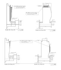
Between the curtain wall and the floor slab are 1-½ hour rated smoke and fire seals represesnted with the symbol Tpy. for typical. These seals prevent the transfer of smoke and fire from one floor to the next. At 1/8th scale these sections are missing a few notes but clearly represent components with graphic line wieghts. Vertical dashed lines indicate columns that are in the distance, a heavy oval line indicates the diagonal HSS Tubes that are being cut in section, and the heavy cut lines at the floor are labeled 1-1/2HR floor assembly. Floors three through ten maintain a consistent detail until the curtain wall adjusts back into the building in a diagonal direction for the top four units with integrated fireplaces. The diagonal terminates as a parapet that serves two functions; the guardrail for the accessable terrace and temporary cover for the davit base plate and arm.
5
Building Enclosure: Wall Section
in the 300 series. A gathering of these details together will develop a proper wall section.
Building Enclosure: Building Detail
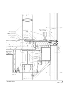
The Building Enclosure has two layers of structural systems. The primary structure of the building is supported with circular columns and I-section beams. A secondary structure is installed to support the curtain wall to each floor slab. The detail below explains that connection. The curtain wall is double-glazed, one layer of glass that is ceramic fritted, an argon gas insulator, and another layer of glass inside. A plastic spacer seperates the two layers of glass.
The cassette aluminum clamp and extrusion hold the glass that are pinned to the steel plate and welded steel angles. This entire assembly makes for the support structure of the curtain wall unit. These curtain wall units are arranged to make megapanels using a spreader beam to anchor them to the facia of the structural slab.
The section explains the edge detail of the curtain wall panels attaching to the reinforced floor slab. The spreader beam is welded and pinned to the anchor channel of the reinforced floor slab, with the latter being supported with fireproofed I-section beams. The section beam is welded to the steel framing that becomes the secondary support to the structure. The detail also explains the strategic placements of smoke seals at the steel angles between the reinforcement of the concrete slab and the spreader beam. There is also fire compression in the gap between the curtain wall and the face of the structural floor slab to stop the spread of smoke across the floors.
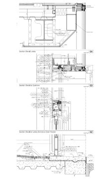
All these structural members are concealed within a framed gypsum board ceiling soffit. The soffit terminates as a shluter strip creating a ½ inch reveal before the custom shaped shade box. The custom shade box has an angled profile to open the volume towards the edge of the room and is angles obtusely from the interior of the curtain wall.
There is a ½ inch reveal provided between the stainlesssteel closure above the steel plate on the edge near the curtain wall and the finished floor slab. A floor-mounted heating system is installed that runs along the perimeter of the floor slab.
The strange dotted graphic outside the glass represents intermittent stabilization anchors (I.S.A) which are used for the window washing platform.
ARCH 8873: INTEGRATED BUILDING SYSTEMS III
INSTRUCTORS:
RUSSEL GENTRY MICHAEL GAMBLE HOWARD WERTHEIMER TODD MOWINSKI
PHASE II 10.14.2022
TEAM 10
BOSTON, MASSACHUSETTS
DRAWN BY MACKENZIE SHINNICK PATRICIA RANGEL ERIC TROLLINGER ARCHI SHAH KISHORE KANDASAMY
SHEET TITLE TRANSVERSE BUILDING SECTION
SHEET NUMBER A201
ARCH 8873: INTEGRATED BUILDING SYSTEMS III
ARCH 8873: INTEGRATED BUILDING SYSTEMS III
INSTRUCTORS: PHASE II 10.14.2022
TEAM 10
BOSTON, MASSACHUSETTS
DETAILS
SHEET NUMBER A602
Tabulation Of Column Loads
SUPPLEMENTAL DEAD LOAD (SDL):
ONE-WAY JOIST SYSTEM - REINFORCED CONCRETE slab span / 20 concrete unit weight x slab depth beam span/ 16 beam depth - slab depth) x beam width x concrete unit weight (18”-5”/12”) x 1.33’ x 150 lbf/ft
3 x (width + length)
3 x (60’ + 150’) total beam length x beam weight
630’ x 216.125 lbf/ft total beam weight / (length x width)
136,158.75 lbf / (150’ x 60’) slab weight + areal weight of beams
62.5 lbf/ft + 15.12 lbf/ft floor self weight + SDL + LL) x beam tributary width lbf/ft + 20 lbf/ft + 80 lbf/ft) x
80 lbf/ft
20 lbf/ft
150 lbf/ft 250 lbf/ft
EXTERIOR COLUMN (1D):
COLUMN LOAD: tributary width: tributary length: tributary area:
Pcol: floor self weight x tributary area x 3 / 1,000 (170.66 lbf/ft x 513.6’ x 3) / 1,000
ARCH 8873: INTEGRATED BUILDING SYSTEMS III
INSTRUCTORS:
PHASE II
10.14.2022
INTERIOR COLUMN (2G):
COLUMN LOAD: tributary width: tributary length: tributary area:
Pcol: floor self weight x tributary area x 3 / 1,000 (170.66 lbf/ft x 513.6’ x 3) / 1,000
TEAM 10
CORNER COLUMN (3I):
COLUMN LOAD: tributary width: tributary length: tributary area:
Pcol: floor self weight x tributary area x 3 / 1,000 (170.66 lbf/ft x 513.6’ x 3) / 1,000
BOSTON, MASSACHUSETTS
DRAWN BY MACKENZIE SHINNICK PATRICIA RANGEL ERIC TROLLINGER ARCHI
SHEET TITLE
TABULATION OF COLUMN LOADS
SHEET NUMBER S601
Prada Building Tokyo: Creating a Plaza Where No Square Meter was Unoccupied
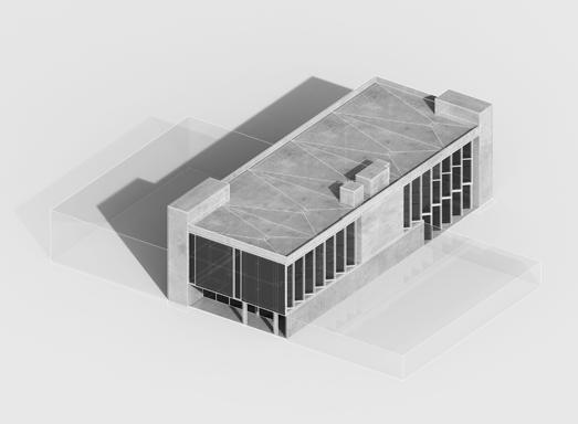
The 2003 Prada Building in Aoyama, Tokyo was a defining project for the Herzog & de Meuron team. A thorough analysis of the ratios, scales, forms, diagrids, facades, elevations and street grid were done to determine the method used by the original architecture firm in designing the building by a team of three graduate students. A formula was constructed after determining the dimensions of a rhomboid unit to develop the floor plan of the building. The base of the massing is the floor plan that strategically begins with a dot on the ground that sits in the corner of an alley and a sidewalk in Toyko, Japan. From that point, architects Herzog & de Meuron make a deliberate move that slightly shifts two equal distant parallel lines. The vertex of those lines then determine the length and angle of the corresponding walls that become the main entrance and plaza of the Prada Aoyama building. The second most important piece of the massing is the roof line that connects all the vertex heights to one of its two ends. The unit of measurement of the rhomboid was determined to be 200mm in height and 3200mm in length. A sectional study also revealed repetitive ratios of 2:5 within the wall area, verrtical walls, and catilevered floors of the structure.
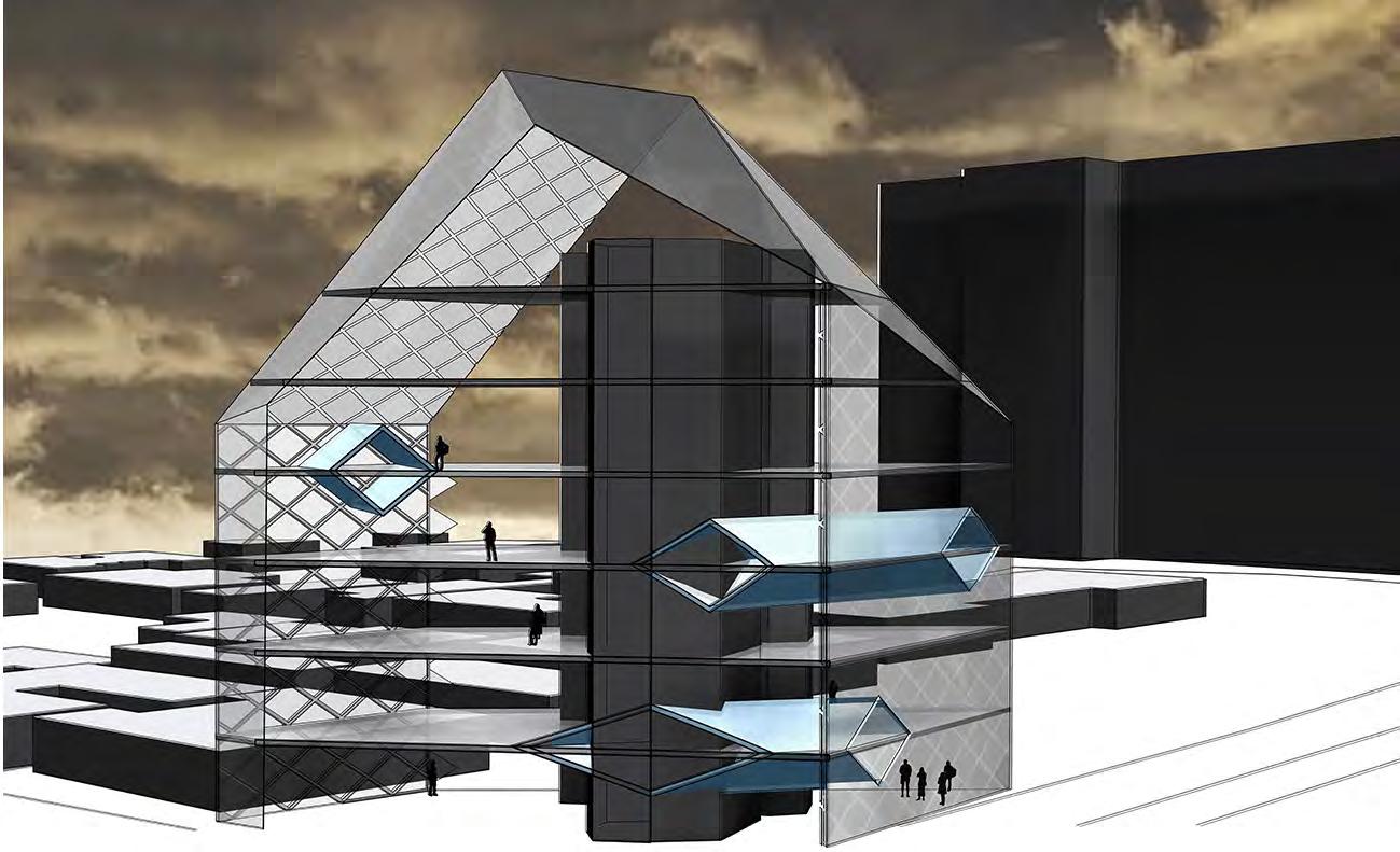

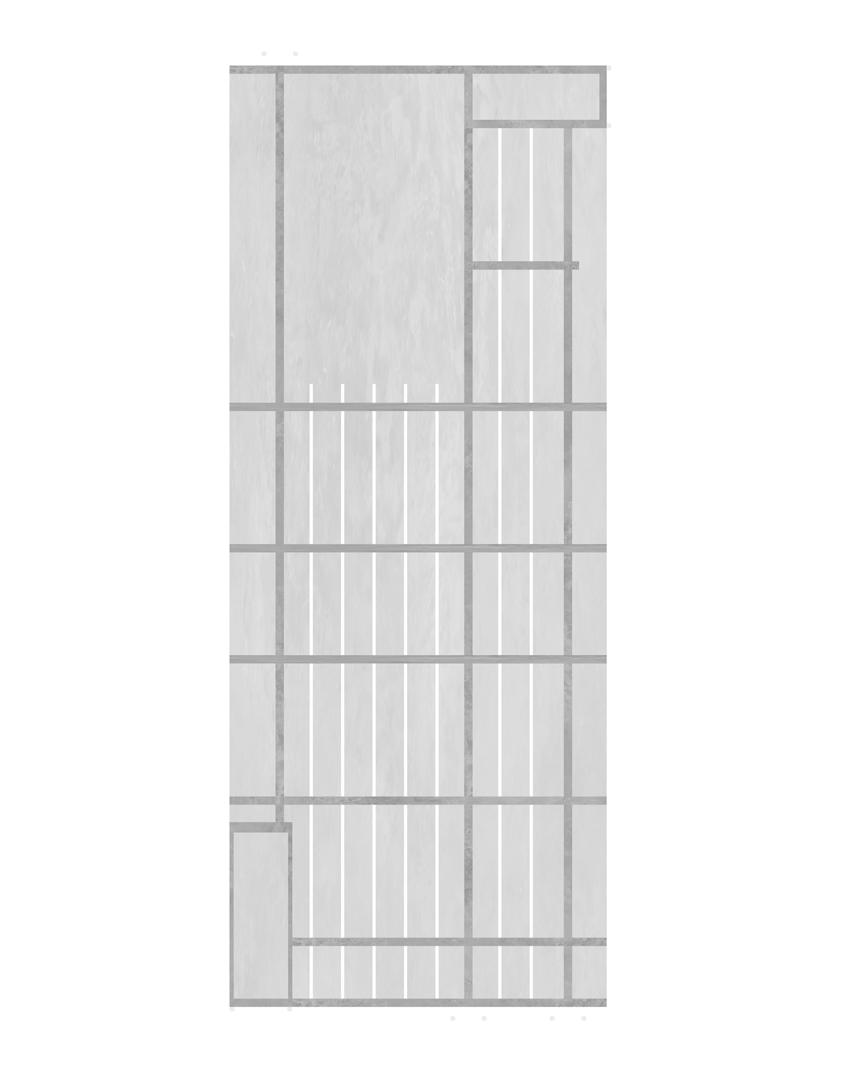
EAST SECTION Scale 1 : 250
When examining the two full oors of the building there is a 2:5 ratio in terms of the diamond height of the 2nd and 5th oor. The light blue shaded area represent the sections of the east-facing wall that contains a ceiling height of two diamonds. As a portion of the total area of the wall, the quantity of oor space that contains two diamond height ceilings is approximately 40% or a 2:5 ratio.
The vertical wall ratios have a strong 2: 5 ratio on the section facing east. When the mullions at the ceiling points are extruded down to their opposite wall, a clear 2:5 ratio is seen on the oor and along the northern and southern walls of the structure.
The pattern of the cantilevered oors from a vertical perspective terms of diamond height dimension. In terms of a horizontal against the eastern wall the sequence follows a 3-5-3-3 length falling across a span of six diamonds as opposed cantilevered oors.
CANTILEVERED FLOORS Ratios perspective goes 2-4-2-4 in horizontal diamond length 3-5-3-3 pattern. With the nal opposed to seven in the rst three
East Section
West Section
As is seen by these diagrams of the east and west elevation and sections, in the entirety of the building, only the second oor is able to maximizes the entire surface area of the building’s footprint. The fourth oor because of the third tunnel is cantilevered on the east wall, though it appears complete on the west wall. The fth oor, although not cantilevered, takes up a smaller footprint due to the angle of the roof. Therefore the 2:5 ratio exhibits itself once again by by establishing a center of stability on the second of seven levels.
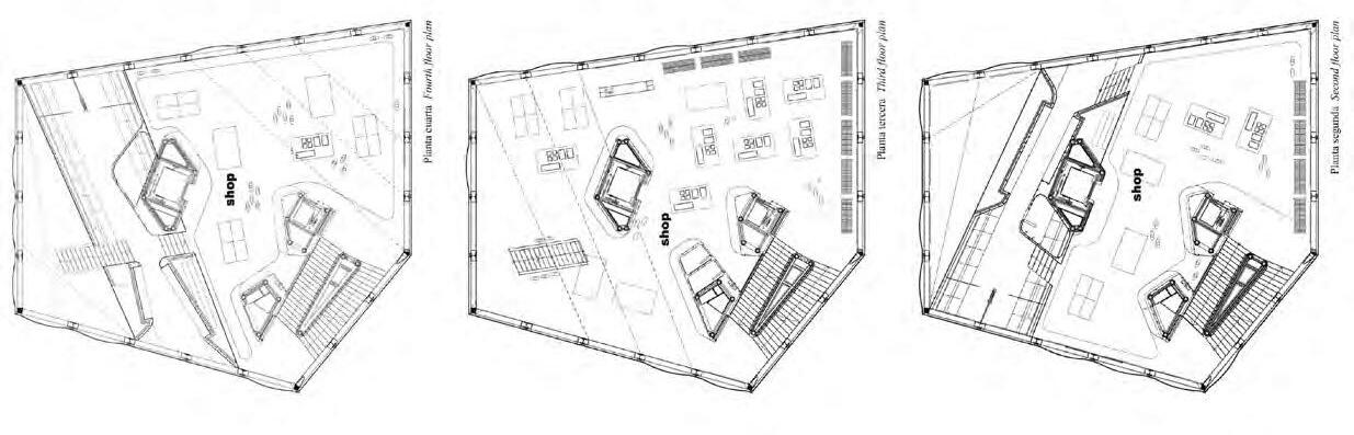
Unit of Measurement

The base of the massing is the oor plan of this building. And the oor plan strategically begins with a dot on the ground that sits in the corner of an alley and a sidewalk in Tokyo, Japan. From that point, architects Herzog & de Meuron make a deliberate move that slightly shifts two equal-distant parallel lines. The vertex of those lines then determine the length and angle of the corresponding walls that became the main entrance and plaza of the Prada Aoyama building. The second most important piece of the massing is the roof line that connects all the vertex heights to one of its two ends.
Begin with a dot at the plan-SW.
3 + 5 rhomboid lengths variable walls
Begin with a dot at the plan-SW.
Procedure by drawing a line at zero degrees, four rhomboid lengths along the site boundary at plan-S.
Draw a line that is seven rhomboid lengths plan-north and reorient it to be 98 degrees from original line.
Then, draw a parallel line to the original line at a length of four rhomboid lengths.
At the plan-N and plan-S vertices, draw two circles, one with a radius of three rhomboid lengths, one with a radius of ve rhomboid lengths.
Connect the vertices to the intersection of these two circles closest to plan-E. The lines connecting these points will form the nal two walls of the building,
Connecting all the lines will create the oor plan of the Prada Ayoama building in Tokyo, Japan.
5 + 8 rhomboid lengths variable walls
8 + 5 rhomboid lengths variable walls
7 + 4 rhomboid lengths variable walls
6 + 11 rhomboid lengths variable walls
3 + 5 rhomboid lengths variable walls
9 + 6 rhomboid lengths variable walls
5 + 3 rhomboid lengths variable walls
4 + 7 rhomboid lengths variable walls

9 + 3 rhomboid lengths variable walls