1 minute read
Working Principles of Three Phase Transformers


The working principles of three phase transformers are based on electromagnetic induction, where the transformation of electrical energy occurs between three interconnected coils, also known as windings.
Phases and Windings:
Advertisement
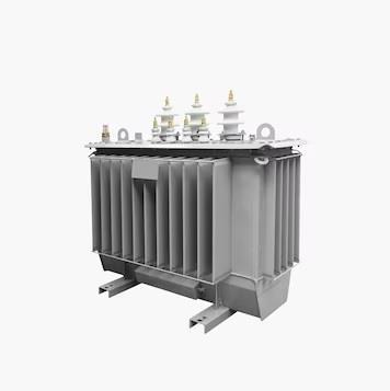
Three phase transformers have three windings, each connected to a separate phase of a three phase power supply. The windings are wound around a common iron core, and each winding is labelled as the primary winding (input) or the secondary winding (output).
Three Phase Transformer Operation:
When a three phase power supply is connected to the primary winding, it creates a magnetic field in the iron core, which induces voltages in the secondary windings. The induced voltages cause currents to flow in the secondary windings, which are then used to power loads connected to the secondary side.
Phasor Diagrams:
Phasor diagrams are used to represent the voltages and currents in three phase systems. In a three phase transformer, the primary and secondary windings are represented by vectors, with their magnitudes and angular displacements representing the voltages and currents.
Voltage and Current Relationships:
In a three phase transformer, the primary and secondary windings are connected in either delta (Δ) or wye (Y) configuration. The voltage and current relationships depend on the winding connections and vector group. In a delta-wye connected transformer.