Translation of original operating manual
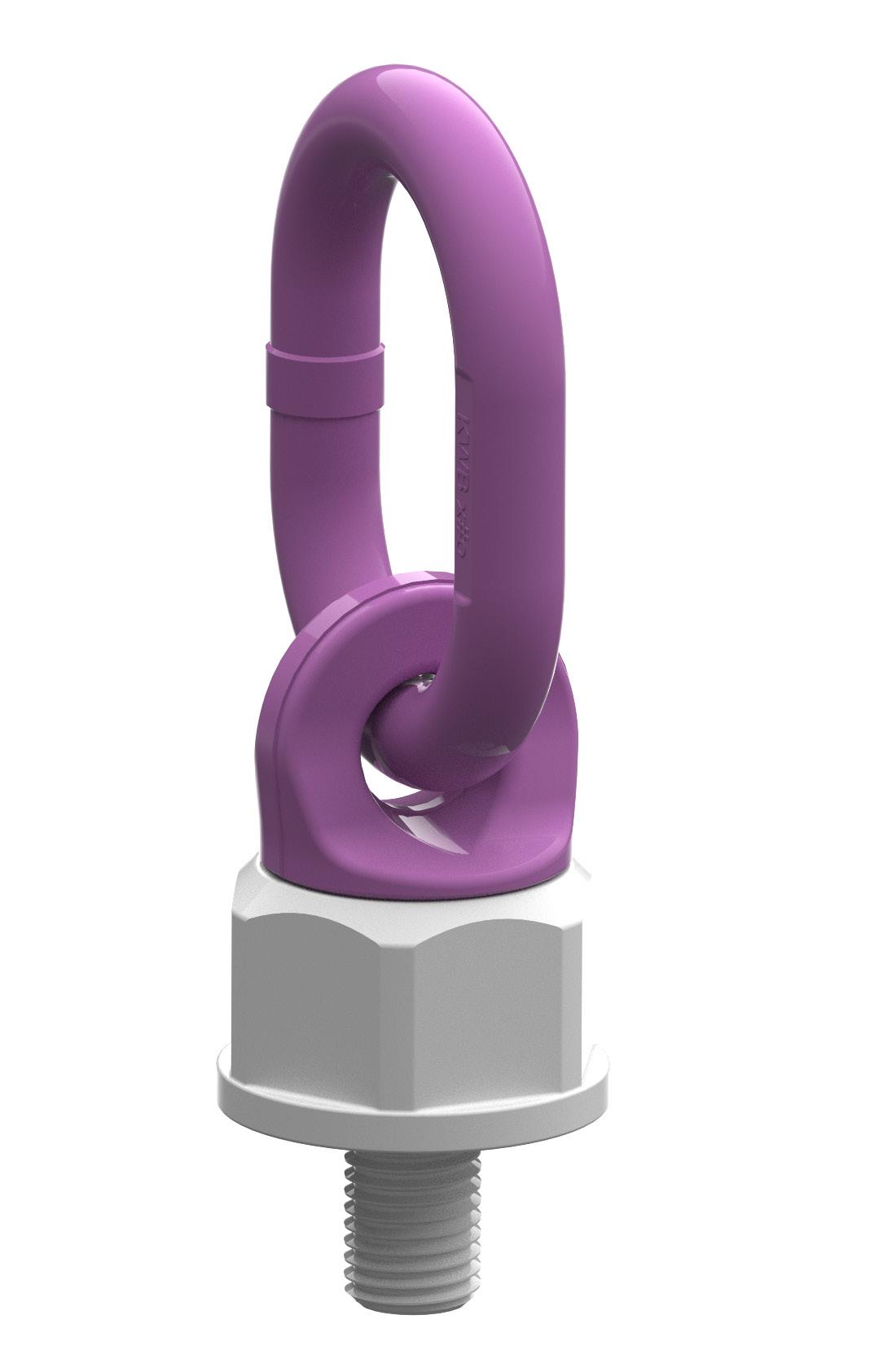
ULD lifting point
Read this operating manual carefully before using this product, paying particular attention to the sections on safety and assembly. This product is suitable for the lifting and holding of loads, provided that the instructions of this operating manual and all the national regulations are complied with. This product may only be used, once this operating manual has been read and understood in full.
This operating manual is part of the product and must be made available to users throughout the lifetime of the product.
The operating manual must be passed on to later owners or users together with the product. If the product is resold, the reseller must provide the instructions in the language of the target country. This operating manual is subject to an ongoing improvement process and is therefore only valid in its most recent version. This is available for download on our website.
The highlighted sections in this operating manual contain information on areas with a particularly high risk potential. Disregarding this information may cause serious injuries or death. Please pay particular attention to these sections.
Document version:
ULD_R1.1_ENG Release date: 2026-04-01
Table of contents
1. Safety instructions
2. Intended use
2.1 Restrictions on use
2.2 Foreseeable misuse
2.3 Identification
3. Mounting instructions
3.1 General
3.2 Safety measures to be taken by the user
3.3 Residual risks
3.4 Mounting
3.5 Dismounting
4. Maintenance, inspection, repairs
4.1 Inspection
4.2 Elimination criteria
4.3 Accident and incident procedure
4.4 Maintenance
4.5 Repairs
5. Storage
6. Decommissioning Tables
1. SAFETY INSTRUCTIONS

A wrongly mounted or damaged lifting point as well as improper use can increase the risk of accidents leading to injuries and/or death!
Damaged lifting points (see maintenance instructions) may fail even during normal conditions of use. Such lifting points may not be used.
• Only specially trained personnel are allowed to use this product. They must be familiar with the relevant norms and the country-specific regulations.
• The user of this product must be in good health. He/she is not allowed to be under the influence of drugs, alcohol or medication.
• Please make sure that in the event of an emergency, a rescue plan is available that covers all emergencies that may occur during use.
• The product may not be modified in any way.
• All repair and maintenance activities must be performed in accordance with the instructions given in section 4.
• Check for visible damage (deformations, cracks, damaged threads) prior to each use and ensure that the product is functioning correctly – lifting points have to be rotatable (alignable with the load direction).
• This product may not be used for the lifting or securing of persons.
2. Intended use
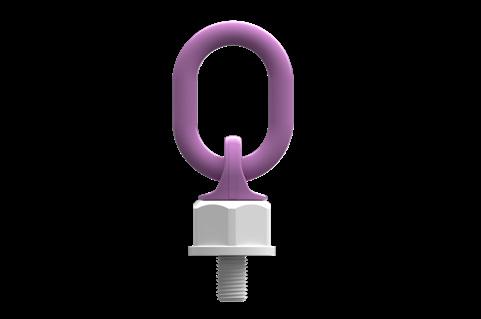
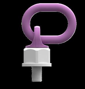
Purpose: The KWB ULD is a lifting point that is screwed onto loads so that lifting chain components (hooks, shackles, straps...) may be attached to enable the load to be lifted.
Lashing: The lifting points may also be used as lashing points. Since only a safety factor of 2 has to be taken into account when lashing, the admissible lashing capacity is twice the nominal load capacity
LC in daN = 2x nominal load capacity in kg (e.g. nominal load capacity 4,000 kg when lifting -> 8000 daN admissible lashing capacity). This product may only be used either for lifting or for lashing. Once a lifting point has been used for lashing, it may no longer be used for lifting (and vice versa). Products that are marked with the admissible lashing capacity instead of the rated load capacity may only be used for lashing and never for lifting.
Target groups: This product may only be used and serviced by properly trained personnel, provided that the instructions of this operating manual and all relevant country-specific regulations are complied with. Repairs, regular inspections and the exchange of parts may only be performed by competent personnel.
Also see point 4 of this operating manual.
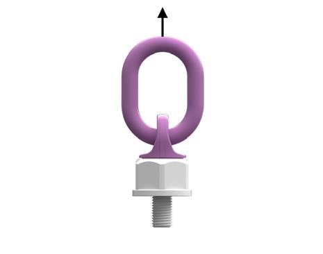
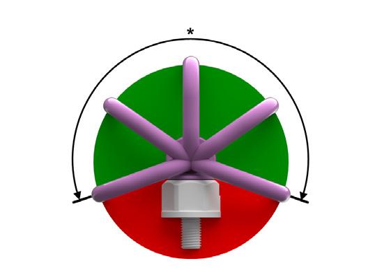
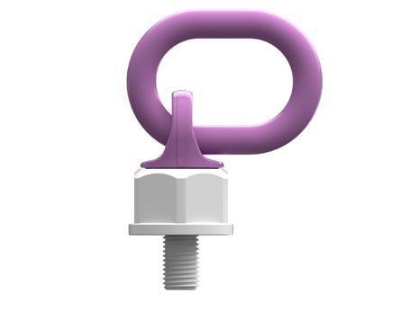
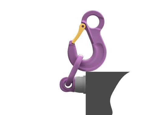
Load: Loading must always take place in the stated direction (picture 1) with the maximum load capacity according to table 1 and taking into consideration the operating conditions as specified here.
Operating temperature: The long-term permitted ambient temperature must be between -20 °C and +200 °C. In case of usage outside this temperature range, the reduction factors outlined in table 2 must be taken into account.
Impacts: Slight shocks, such as the kind that is caused by acceleration during lifting and lowering of the load, may be disregarded. Stronger shocks are not permitted.
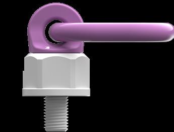
Other information: Use only original parts for the assembling of the lifting point. The ring is 360° rotatable around the screw and must be aligned with the expected direction of pull prior to loading.
Although the upper part has a ball bearing and rotatable 360°, before usage you should adjust the ring in the correct direction of tension (picture 1). That applies in particular when lifting with multi leg slings. With a non-aligned ring (forbidden load acc. to picture 2), the ring holder could turn suddenly under load, and cause high risk for the load and/or people.
For exact dimensions, refer to our website.
2.1 Restrictions on use
• These lifting points are not suitable for use in areas with strong corrosive influences (e.g. in the vicinity of sewage water or chemicals). They must not be exposed to acids or caustic solutions and their vapours.
For use in environments containing chemicals, please consult our technical service.
• The ring/bracket is not suitable for edge or corner loading.
• Do not use lifting points as a choke-hitch.
• For the load capacities to apply, it is assumed that the individual lifting points are placed under load symmetrically. When the load is lifted, this will result in the same angles of inclination of the individual chain legs.
• In case of asymmetrical loads, you must take into account the following:
1. The load is less than 80% of the indicated load capacity.
2. The angles of inclination of all chain legs are not lower than 15° and are very similar (i.e. only differ by a maximum of 5°).
3. For three- and four-leg lifting chains, it must be ensured that the corresponding plan angles are within 15° of each other.
If any of these conditions are not met, only one strand may be considered load-bearing (see load capacity table).
• May not be rotated continuously under load.
• The ring may not be folded up and down continuously while under load.
The information contained in this operating manual is based on the assumption that no particularly hazardous conditions apply. Such conditions include offshore use and use in areas with nuclear contamination.
2.2 Foreseeable misuse
• Used by inadequately trained personell
• Used by personnel who are unable to fully comprehend the language of this operating manual.
• Attachment to components for which no operating manual or proof of strength is present or available.
• Attachment of inappropriate lifting devices.
• Attachment of lifting equipment for which no instruction manual or inspection based on applicable standards is present or available.
2.3 Identification
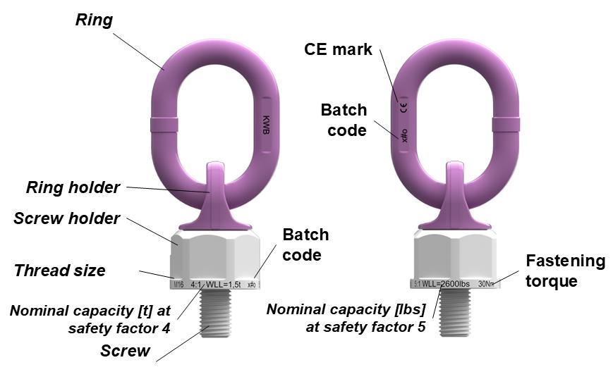
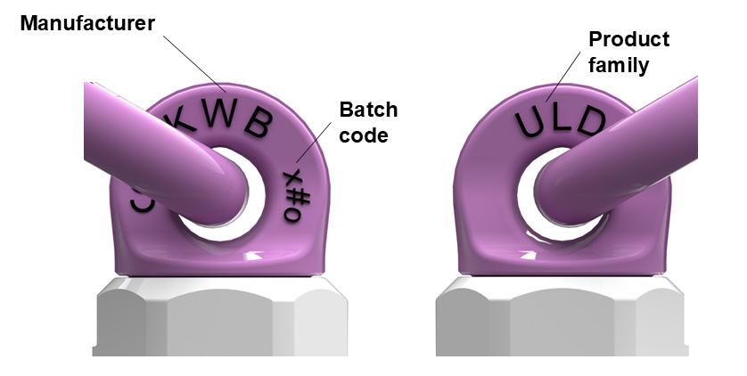
Every KWB lifting point is labelled with its maximum load capacity for adverse loading conditions as well as the manufacturer’s code and batch number. The picture below shows the exact identification details on the product.
3. Mounting Instructions
3.1 General
• Mounting must only be carried out by persons who have received instructions on the safe use of the product and who have the required knowledge and skills for the task.
• Only original KWB parts may be used. – These are recognisable from the stamp (batch number, manufacturer logo...).
• Only use non-defective lifting points.
• Used lifting points must be checked according to the maintenance instructions prior to each use.
• Check that the lifting point has been attached according to the assembly instructions during each use.
• Attach lifting points in such a way that they may be reached easily and without obstruction when attaching or removing the lifting element. Check that no hazardous points are created that could endanger the user or impede correct usage (risk of crushing, pinching or collision).
• The attached lifting device must be free to move in the ring.
• Keep lifting points clean and dry. Treat carefully even after use. Do not let them drop to the floor as this may damage the thread or other parts.
• The base material of the object to which the lifting points are to be attached must be strong enough to absorb the forces that occur without deformations (proof of safety).
• Always choose lifting points with the correct dimension acc. to the load capacity table, depending on the size of the load and the arrangement of the lifting devices.
• Choose the arrangement of lifting points in such a way that symmetrical loading is assured and the centre of the load is positioned under the lifting point(s).
• When choosing your arrangement, check that there is no risk of improper loading due to any of the following factors:
- direction of pull is obstructed
- direction of pull is not within the indicated area (picture1)
• Any severe conditions (see restrictions on use) must be taken into account.
• Always refer to the user manual and mounting instructions for the lifting devices used and, where applicable, also for the load to be lifted.
• For custom-made designs: Take into account the additional information provided and the specifications on the customer`s drawings (where applicable).
• The delivery condition must not be changed. It is not permitted to perform welding, heat and/or surface treatments with material-damaging effects.
• The length of the thread may not be shortened.
• Do not use an extension when assembling.
• Only use the lifting points in a nut thread that is true to gauges.
3.2 Safety measures to be taken by the user
Always take into account the restrictions on use and the maximum load capacity of the lifting points used. Always wear safety gloves when attaching the lifting device. Align the lifting point in the expected direction of pull and leave the hazard area before lifting the load. Slightly tension the chain sling and check that the lifting devices are correctly fitted to the lifting points and that all lifting points are correctly aligned in the direction of pull before lifting the load.
Keep a sufficient safety distance during the lifting operation and ensure that the load has been lowered safely before removing the lifting device. Do not overload lifting points! Falling loads may cause injury and/or death!
3.3 Residual risks
Overloading caused by non-compliance with the maximum load capacity or adverse environmental factors (temperature...). Incorrect assembly of the lifting points may lead to failure, as may the use of non-authorised or damaged parts of the attached lifting device.
3.4 Mounting
• The screw-on surface must be level and have at least the diameter of the contact surface of the lifting point. The sufficiently deep, threaded hole must be at the centre of the contact surface, at a right angle. It must be possible to insert the screw fully (with blind holes).
• Clean the threaded hole prior to each use and check for damage.
• The minimum screw penetration values are: M8 to M20:
1,5 x M for steel (Rm > 360N/mm²)
1.75 x M for cast steel
2.5 x M for aluminium from M24 up:
1,2 x M for steel (Rm > 360N/mm²)
1.5 x M for cast steel
2.2 x M for aluminium
(M = thread size, e.g. M20 = 20 mm)
• Additional elements (such as washers) between the lifting point and the load are not permitted.
• Prior to each use, ensure that the lifting point is fully screwed in and that the contact surface is flush with the load.
• For one-off transport, it is admissible to tighten the screw by hand using a spanner.
• If the lifting point is intended to remain permanently attached to the load, it must be tightened with an appropriate tool with a torque as listed in table 1. If necessary (i.e. in case of vibrations), the thread must be secured with a liquid threadlock (e.g. Loctite).
• Should the lifting point be rotated under load when used, please ensure that it is properly fastened with torque.
• After assembly, ensure that there is no risk of incorrect loading by aligning the lifting point in the expected load direction by moving the ring.
• When turning loads, make sure that the lifting device only touches the lifting point on the ring.
• During rotation and turning operations under full load, increased wear may occur on the ring and ring holder. Any sharp edges that develop should be removed as soon as possible.
3.5 Dismounting
To remove the lifting point, unscrew it with a suitable tool. Store the product as described in „Storage“. Take appropriate measures to protect the thread on the load from damage and dirt.
4. Inspection, maintenance, repair
The safety of the user is contingent upon the effectiveness and durability of the equipment used. For this reason, ensure that inspections are performed regularly. Damaged lifting points may fail during normal conditions of use, causing the load to fall. Such lifting points may not be used.
• This product must be inspected by a competent person at least once a year and in accordance with the manufacturer‘s instructions. Depending on the conditions of use and legal stipulations, this interval may be shorter. In case of frequent use, we recommend a crack test every two years.
• During inspection, all parts must be checked for damage that could impact safety and function.
• For the regular inspection and the crack test, all parts must be free from oil, dirt and rust. Appropriate cleaning processes include those that do not cause overheating, cover up surface defects or cause hydrogen embrittlement or stress crack corrosion.
• Load testing all the way up to the proof force is not permitted for these lifting points.
Competent persons are persons who are capable of assessing the operationality and correct usage of this product, either based on their technical qualifications (e.g. training) or their experience with and sufficient knowledge of the use of lifting points, and who are familiar with the relevant standards and regulations. If you are interested in an expert training module, please contact our technical service.
4.1 Inspection
Before each use, the following checks should be performed:
• The lifting points were selected correctly, based on the size of the load and the lifting devices used (chain sling, angle of inclination, etc.).
• Flawless functioning (rotating and/or folding of the ring) and appearance of parts and the thread.
• After screwing in, the contact surface must fully rest on the load.
• The ring of the lifting point used must be aligned with the expected load direction.
• The locking screw must be in place and must not have become loose.
Regular inspection:
Regular inspections must be performed by the manufacturer or a competent person, in strict accordance with the manufacturer‘s instructions.
4.2 Elimination criteria
• Breakage, deformations, sharp notches or cracks of any kind.
• Signs of excessive heat exposure (e.g. black discolouration, burn marks in the coating).
• Visible damage to the thread that could impair the correct functioning of the product.
• Illegible markings.
• Wear or excessive corrosion, if the admissible cross-sectional reduction of 10 % is exceeded.
• If it is not possible to freely rotate and/or fold the ring after assembly.
• The maximum service life of the product, taking into account the intended use is a maximum of 20,000 load cycles. Please note that several load cycles can occur during a lifting operation.

If there is any doubt on the correct functioning/ safety of the lifting point, it must be discarded!
4.3 Accident and incident procedure
If the lifting device gets jammed in the ring of the lifting point, do not use force to release it as this may cause damage. If the lifting point shows signs of deformation (e.g. due to overloading or other unusual events), the product must be removed from service and handed to a competent person for inspection or repair.
4.4
Maintenance
• If necessary, clean all the parts using a damp cloth. Leave the lifting point to air-dry.
• The thread may be cleaned using a wire brush.
4.5 Repairs
• Inspections and repairs need to be fully documented and remain with the product for the duration of its operating life.
• Repairs may only be performed by the manufacturer or a com-
petent person.
• Small cuts, notches and grooves may be removed by careful grinding or filing. After the repair, the treated area must merge smoothly with the surrounding area, without the cross-section changing abruptly. By fully removing the defect, the dimension of the area must not be reduced by more than 5 %.
• Welding and heat treatment is not permitted.
5. Storage
This product must be stored in a clean and dry condition and protected against corrosion (e.g. lightly oiled). The lifting point must not be exposed to corrosive, thermal or mechanical influences during storage or transport. The thread should be protected by an appropriate protective cap or net.
6. Decommissioning
The product has a high metal content and is fully recyclable. At the end of its lifespan, the product must be recycled in accordance with local regulations.
Prior to using this product for the first time, the operating manual must have been read and understood in full.
This declaration becomes invalid with every modification of the product not approved by pewag or if the product is not used in a way described within the user manual.
KWB Ketten Austria GmbH
A-9020 Klagenfurt, Schleppe-Platz 8
Phone: +43 463 48 80-355
Fax: +43 463 48 80-350 kwb@kwb-ketten.at, www.kwb-ketten.at
Subject to technical modification and printing errors. Depending on the surface finish, the illustrations in the manual may differ in color from the delivered product.