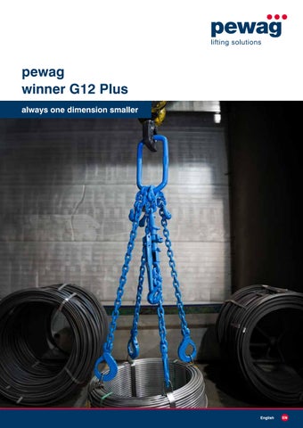
pewag winner G12 Plus always one dimension smaller
English
EN
pewag shackles Built to secure. Made to endure. Discover pewag shackles – made in Europe to the highest standards for maximum safety and load capacity.
View the catalogue here:
2
pewag winner G12 Plus
Table of contents We are part of the pewag group
4-5
Lifting
6-37
Lifting with winner G12 Plus
6-7
Working load limit table and severe operating conditions
8-9
Order example for a chain sling
10
Working load limit tag
12
Chain
13
Master links and master link assemblies
14-27
Lifting accessories
30-37
Lashing
40-57
Lashing with winner G12 Plus
40-41
Order examples for lashing chains
42
Lashing tag
43
Reference tables for selecting the right lashing equipment
44-45
Dynamic coefficients of friction & lashing capacities
46-47
Lashing accessories
48-53
Lashing chains
54-57
Spare parts
58-63
User information
64-68
User information (general)
64-65
User information (lifting)
66-67
User information (lashing)
68
Subject to technical changes and printing errors.
pewag winner G12 Plus
3
pewag group
We are part of the
LEADING TO EXCELLENCE striving for excellence in QUALITY The values of the pewag group brands are demonstrated by our first-class quality and continuous innovation. You can rely on us.
pewag lifting solutions is part of an internationally operating group of companies. Our success story goes back to the year 1479.
striving for excellence in RESPONSIBILITY Our goal is CO2 neutral production by 2030. We live sustainable and fair partnerships and an open way of working together. We take on social as well as environmental responsibility.
W H AT D R I V E S U S Through our entrepreneurial spirit - shaped by the joy of innovation - we strive to offer the best solutions for the market. Today and in the future.
striving for excellence in ENTREPRENEURSHIP Through the specific expertise of each individual and decentralized responsibilities, we ensure healthy growth and a sustainably successful future.
The high quality of our brands, products and services, as well as the passionate commitment of our employees are our most valuable assets to exceed customer expectations and to live up to our corporate responsibility towards people and environment.
striving for excellence in TECHNOLOGY We ensure our technological strength by striving for quality, continuous improvement and innovation of our products and production processes.
FROM AUSTRIA....
1479
1787
1803
1836
1912
2009
2021
First documentary mention of the forge
Foundation of the chain forge in Kapfenberg
Foundation of the location in Graz
Establishment of an iron casting plant in Brückl
Production of the first pewag snow chain
pewag develops into an international group of companies
Extensive investment in renewable energies. Goal: CO2neutral production by 2030
. . . . A C R O S S T H E G LO B E
100+ Countries
50
45
Sales and other locations
Sales partners
18 Production sites
15+ Brands
5 Continents
4
pewag winner G12 Plus
pewag group
I N A S U S T A I N A B L E W AY Social Excellence The corporate ethics of the pewag group are based on our clear commitment to universal human rights. As a globally active group of companies, we bear a social and corporative responsibility. This applies in particular to our employees. Their occupational safety and health protection are our top priority. We promote their personal and professional development and foster a culture of open, honest, non-discriminatory and team-oriented exchange based on transparent communication. We apply the same standards in our dealings with customers, suppliers and other business partners.
Environmental Excellence We are committed to a careful and sustainable approach to the environment. This applies to all areas and activities of our group of companies. For us, it is a matter of course to use resources as efficiently as possible and to ensure this also in the future through new environmentally friendly and efficient processes. We are continuously working to optimize the durability and recyclability of our products. In this context, one of our core concerns is to continuously improve our energy efficiency and thus reduce energy consumption in the long term. The energy we use comes from renewable energy sources and is already partly generated by ourselves.
W H AT D E F I N E S U S
Snow and forestry chains
Hoist and conveyor chains
Do-it-yourself
Engineering
Lifting solutions
Tire protection chains
Our Expertise.
Our Network.
Our Experience.
Our international brands have an extensive and diverse range of products and services.
With over 50 locations on five continents, the pewag group forms a global platform of product specialists, partners and suppliers.
Based on centuries of experience, genuine craftsmanship and innovative technologies we process the highest quality materials with the claim to offer the best solutions on the market.
The portfolio ranges from traction chains for tires, tire protection chains for mining vehicles over a wide range of technical chains and innovative lifting solutions up to products for the do-it-yourself area as well as forming technology.
This community is strengthened by a large network of external experts from science, research and development and a wide range of brands and companies within the group.
What unites us as people within the pewag group is the strong ambition for continuous development.
pewag winner G12 Plus
5
Lifting with winner G12 Plus Slinging with G12 Plus
Practical overview
Lifting with winner G12 Plus From an established standard to technological excellence Many G8 chain slings are still in use worldwide. G8 was the established standard for many years – but today, this technology has clearly reached its limits. Their high dead weight, lower working load limits and relatively high material use make G8 chain slings increasingly inefficient and outdated. As a market and innovation leader, pewag is consistently driving technological innovation. pewag presents winner G12 Plus, a modern chain system that not only replaces G8 but clearly outperforms it in every respect. Our goal is to replace G8 gradually with a more efficient, lighter and more sustainable solution.
Why winner G12 Plus is the better solution Higher working load limits winner G12 Plus impresses with at least 50 % higher working load limits than G8, setting new standards in lifting technology. Reduced weight with intelligent downsizing Its higher working load limits allow winner G12 Plus chain slings to be one dimension smaller than equivalent G8 chain slings. This significantly reduces the dead weight, makes handling easier and improves ergonomics. Top-quality material. Modern manufacturing technologies Designed in Austria. Made in Europe. Made from premium materials, winner G12 Plus products represent durability, reliability and state-of-the-art technology.
Discover pewag winner G12 Plus in 3D You can now explore our products virtually: The QR code takes you to interactive 3D models that you can rotate, zoom and view from any angle – complete with all the key product information.
Unique ‘winplus’ profile chain pewag remains the only manufacturer to offer profile chains for chain slings as part of its standard product range, despite the complexity of their manufacture.
Boost your company's efficiency • Downsizing enables the use of smaller, lighter chain slings with the same or higher working load limit • State-of-the-art manufacturing technologies for maximum quality and future-proof performance • Reduced steel consumption means better sustainability Less strain on the user • Significantly lower weight, much easier to handle • Better ergonomics, reduced physical strain • State-of-the-art materials deliver maximum safety
6
pewag winner G12 Plus
Slinging Lifting with with winner G12 Plus G12 Plus
Lifting always one dimension smaller winner G12 Plus is one dimension smaller than G8 but has at least the same working load limit.
Designation Grade – dimension
SA 13 IV G – HSB – P 2000 V
winplus 10 200 IV VSXK – KLH 2000
G8 – dimension 13
winner G12 Plus – dimension 10
WLL
11,200 kg
11,350 kg
+150 kg
Weight
51 kg
36 kg
-30 %
Comparison of working load limits Downsizing from G8 to winner G12 Plus is possible across the entire range.
Grade 8
Grade 12 Plus
DIM
Working load limit* (WLL) [kg]
DIM
Working load limit* (WLL) [kg]
7
1,500
7
2,360
8
2,000
8
3,200
10
3,150
10
5,400
13
5,300
13
8,200
16
8,000
* The working load limits shown are maximum values for single-leg use under the uniform load method.
Note: To improve readability, all markings on components in this catalogue are shown in black. They are actually the same colour as the powder coating.
pewag winner G12 Plus
7
Working load limit table and severe operating conditions
pewag winner G12 Plus working load limits Safety factor 4
1-leg
1-leg (choke hitch)
2-leg
2-leg (choke hitch)
3-leg, 4-leg and 2×2-leg
Inclination angle β
0°
0°
0°-45°
45°-60°
0°-45°
45°-60°
0°-45°
45°-60°
Load factor
1
0.8
1.4
1
1.12
0.8
2.1
1.5
7
2,360
1,900
3,350
2,360
2,650
1,900
winplus 8
8
3,200
2,550
4,450
3,200
3,550
winplus 10
10
5,400
4,300
7,550
5,400
6,050
winplus 13
13
8,200
6,550
11,450
8,200
winplus 16
16
12,800
10,250
17,900
12,800
Code
Dimension
winplus 7
Working load limit under general conditions of use [kg] 5,000
3,550
2,550
6,700
4,800
4,300
11,350
8,100
9,150
6,550
17,200
12,300
14,350
10,250
26,500
19,200
Working load limit tag (Examples for dim. 10) * see note
* see note
3-leg
4-leg
2×2-leg
* Note: When using this lifting method, the user must limit the working load limit to 80 % of the value shown on the WLL tag.
Thermal loading
< -40 °C
-40 °C to 200 °C
> 200 °C
Load factor
prohibited
1
prohibited
Asymmetrical load distribution
The working load limit must be reduced by at least one leg. Example: Chain slings with three legs or four legs must be rated as chain slings with two legs. If in doubt, only one leg may be considered as load-bearing.
Edge loading*
R > 2 x d*
R ≤ d*
Load factor
1
0.7
0.5
Shock loading
Light shocks
Moderate shocks
Heavy shocks
Load factor
1
0.7
prohibited
* d = chain diameter
8
R > d*
pewag winner G12 Plus
Working load limit table and severe operating conditions
4-leg and 2×2-leg with load distributor
Endless chain slings
Single lifting slings (basket hitch)
Double lifting slings (basket hitch)
0°-45°
45°-60°
0°
0°-45°
45°-60°
0°-45°
45°-60°
2.8
2
1.6
1.4
1
2.1
1.5
6,700
4,750
5,000
3,550
Working load limit under general conditions of use [kg] 3,800
3,350
2,360
8,950
6,400
5,100
4,450
3,200
6,700
4,800
15,100
10,800
8,650
7,550
5,400
11,350
8,100
22,500
16,400
13,100
11,450
8,200
17,200
12,300
35,500
25,500
20,500
17,900
12,800
26,500
19,200
4-leg
2×2-leg
Even the best quality products lose some of their working load limit under exceptional operating conditions. The working load limits table shows the working load limits under normal operating conditions. The severe operating conditions table lists exceptional operating conditions and the corresponding load factors. The permissible working load limit under these conditions is the product of the maximum working load limit and the load factor in the table. If more than one severe operating condition applies, apply all corresponding load factors! You can find further restrictions on use in the operating manuals. All restrictions specified in the following documents apply: • Original operating manual for pewag winner G12 Plus lifting and lashing components • Original instruction manual for pewag standard lifting chains (only for chain slings) • Original operating manual for pewag lashing chain systems in G8, G10, G12 and G12 Plus (only for lashing chains)
pewag winner G12 Plus
9
Order example for a chain sling
Order example for a chain sling
VLSAG 4-10
pewag chain slings use a standardised designation system which fully describes their design.
Assembly type: Connex
Assembly type: Connex (fully or partially)
Length [mm]
Shortening element
Bottom component
Top component
Number of legs
Chain type
Nominal diameter
Chain
winplus 10 200 IV VLSAG – KLH – P 1200 Connex
P 10
winplus 10 200
L
KLH 10
Number of legs: IV
winplus 10 200 II VSXK - KLH 1250 Length [mm]
Bottom component
Top component
Number of legs
Chain type
Nominal diameter
Chain
VSXK 2-10
winplus 10 200
L
Custom chain slings For applications beyond the standard range, pewag offers customised chain slings on request. Please contact your local pewag CSM representative or send an enquiry to sales@pewag.com.
KLH 10
Number of legs: II
10
pewag winner G12 Plus
Chain sling configurator
Configure now:
Start
Chain sling configurator Always the right solution You can use our chain sling configurator to find the right solution for your lifting applications with ease. The system guides you step by step through the configuration process and provides a technically suitable recommendation based on your input.
Configure and get a quote Select the required grade and sling type, specify the required working load limit and chain length, and add the matching sling components. Within a few minutes, you will get a customised configuration, including all the relevant technical information. After completing the configuration, you can save your selection, share it or request a personalised quote straight away.
Your advantages at a glance Select the right chain sling with ease Support for safe and standards-compliant design Access to technical data and specifications A clear overview of all components Save, share and request quotes instantly
Easy access to your certificates
Explore
With our online certification software, customers can create and access their test certificates and annual inspection reports anytime, anywhere. This ensures quick and seamless access to important documents.
User-friendly interface
24/7 availability
All certificates in one place
The service includes certificates for winner G12 Plus and other pewag product ranges. pewag winner G12 Plus
11
Working load limit tag
Working load limit tag • Corrosion-resistant material: For maximum service life and safety. • Permanent marking: Key information such as grade and working load limit is precisely and permanently laserengraved. • Handy quick-lock link: Quick and secure attachment to the chain sling – also made of corrosion-resistant material. • QR code integration: Direct access to the latest pewag operating manual for chain slings. • Optional with peTAG: For digital identification and smart documentation. • Personalised: Custom laser markings (company logos, etc.) are available on request.
Front (single-leg)
Front (multiple-leg)
Back
Example (for the chain sling ‘winplus 10 200 II VSXK - KLH 1250’):
Number of legs Dimension Manufacturer Product group & grade Chain sling number (traceability code) Working load limits
peTAG for winner G12 Plus On request, the working load limit tag can be supplied with the pewag peTAG – an integrated NFC (RFID) transponder chip for digital identification and management. Combined with the peTAG Manager software solution, the system ensures efficient and transparent data management throughout its entire lifecycle. This makes it easy to record and document product data, which can be accessed at any time. The software also assists with service and maintenance tasks, as well as with the preparation of test reports and certificates. More information on page 38.
12
pewag winner G12 Plus
QR code (operating manual) CE and UKCA marks
Chain
winplus Lifting and lashing chain
Characteristics
• The well-proven profile design guarantees optimal handling in lifting and lashing applications • High-quality powder coating provides effective corrosion protection and an attractive surface finish • Suitable for operating temperatures up to 200 °C
Standards EN 818-2*
WLL [kg]
LC [kN]
L [m]
t [mm]
b1 (min.) [mm]
b2 (max.) [mm]
BF [kN]
Weight [kg/m]
winplus 7 200
7
2,360
47
50
22.3
10.3
26.6
94.0
1.4
winplus 8 200
8
3,200
63
50
25.8
11.5
30.4
130
1.9
winplus 10 200
10
5,400
100
50
34.6
15.0
39.5
214
3.1
winplus 13 200
13
8,200
160
50
41.6
18.3
48.7
322
4.8
dn = nominal diameter, WLL = working load limit, LC = lashing capacity, L = standard supply length, t = pitch, b1 (min.) = (minimum) inside width, b2 (max.) = (maximum) outside width
Manufacturer’s code (’P‘) & grade (’12P‘)
Batch code (part 2)
3rd link
3rd link
Chain type (’200’)
Marking
Batch code (part 1)
Technical details
dn [mm]
Code
1st link
2nd link
Front
2nd link
1st link
Back
Unique profile
Chamfer to prevent indentations on the load (basket and choke hitches)
Improved mechanical properties • Better wear resistance • Greater bending stiffness
Special features
The 4-point contact of the chain links improves handling
Unique profile • Material redistributed from less critical to highly critical areas
Improved handling • Lifting: Better grip (basket and choke hitches) • Lashing: Less chain twist *with modifications for grade G12 Plus
pewag winner G12 Plus
13
Master links and master link assemblies
Practical knowledge winner G12 Plus master links Sophisticated in every detail The master links in the winner G12 Plus product range were specially designed for everyday use. Their clever design delivers outstanding safety, easy handling and a long service life.
Easy identification of the inclination angle The lower section of the master links is angled. This allows the inclination angle to be identified quickly and reliably, even without specialist knowledge. However, it can still be determined using conventional methods. This additional verification is recommended if in doubt.
Inclination angle 0° – 45°: When the connecting links are at the lowest point of the master link, the applicable working load limit is the value for 0°–45° shown on the WLL tag.
Inclination angle 45° – 60°: When the connecting links are at the outermost points of the master link, the applicable working load limit is the value for 45°–60° shown on the WLL tag.
14
pewag winner G12 Plus
Master links and master link assemblies
Perfect fit for the crane hook The upper section of the master links is shaped to fit the crane hook. This creates broad, firm contact between the crane hook and the master link. This shape significantly reduces friction and stress on the material. This protects the master link, minimises wear and extends its service life – a clear advantage in everyday use.
Surface contact Less friction Less wear
2-point contact High friction Heavy wear at contact points
Clear marking for maximum safety All master links in the winner G12 Plus product range are clearly and permanently marked with ‘↑TOP↑’ to prevent any confusion. This clearly visible marking indicates the correct orientation at a glance and helps the user ensure safe and correct use.
pewag winner G12 Plus
15
Master links and master link assemblies
Characteristics
AS Master link • It is intended for use as a master link in 1-leg or 2-leg chain slings • Patented, angled design for indicating the inclination angle (0°–45° and 45°–60°) • Patented, optimised contact surface for ideal force transmission between the master link and the crane hook • Clear, easily legible ‘↑TOP↑’ marking for correct orientation in the crane hook
Standards EN 1677-4*
Technical details
Code
WLL 0° – 45° [kg]
WLL 45° – 60° [kg]
Single hook ** DIN 15401
Double hook ** DIN 15402
1-leg chain slings
2-leg chain slings 7
AS 16
3,350
2,360
2.5
4
7&8
AS 19
5,400
3,850
5
6
10
8
AS 23
8,200
5,850
6
8
13
10
AS 27
12,800
9,100
8
10
16
13
Code
t [mm]
w [mm]
d [mm]
s [mm]
Weight [kg]
AS 16
100
56
16.5
13
0.54
AS 19
130
75
19.0
15
0.93
AS 23
147
84
23.0
18
1.5
AS 27
168
93
27.0
21
2.4
Special features
WLL = working load limit ** The largest crane hook for which the respective product is suitable.
The contact surface is optimised for the shape of the crane hook
0°-45°: Connecting links are at the lowest point of the master link 45°-60°: Connecting links are at the outermost points of the master link *with modifications for grade G12 Plus
16
pewag winner G12 Plus
Master links and master link assemblies
VS Master link assembly
Characteristics
• It is intended for use as a master link assembly in 3-leg or 4-leg chain slings • Patented, angled master link design for indicating the inclination angle (0°–45° and 45°–60°) • Patented, optimised contact surface for ideal force transmission between the master link and the crane hook • Clear, easily legible ‘↑TOP↑’ marking for correct orientation in the crane hook
Standards EN 1677-4*
Consisting of
WLL 0° – 45° [kg]
WLL 45° – 60° [kg]
Single hook ** DIN 15401
Double hook ** DIN 15402
3-leg and 4-leg chain slings
VS 4-7
AS 19 + 2 x B 16
5,000
3,550
5
6
7
VS 4-8
AS 23 + 2 x B 16
6,700
4,800
6
8
8
VS 4-10
AS 27 + 2 x B 20
11,350
8,100
8
10
10
VS 4-13
AS 33 + 2 x B 26
17,200
12,300
10
12
13
Code
e [mm]
t [mm]
w [mm]
d [mm]
t1 [mm]
w1 [mm]
d1 [mm]
s1 [mm]
Weight [kg]
VS 4-7
200
130
75
19.0
70
34
16.5
14
1.7
VS 4-8
217
147
84
23.0
70
34
16.5
14
2.3
VS 4-10
253
168
93
27.0
85
40
19.5
16
3.8
VS 4-13
330
190
110
33.0
140
65
27.0
20
8.0
Technical details
Code
WLL = working load limit ** The largest crane hook for which the respective product is suitable.
Special features
The contact surface is optimised for the shape of the crane hook
0°-45°: Transition links are at the lowest point of the master link 45°-60°: Transition links are at the outermost points of the master link *with modifications for grade G12 Plus
pewag winner G12 Plus
17
Master links and master link assemblies
Characteristics
VLS 1 Oversize master link assembly • It is intended for use as a master link assembly in 1-leg chain slings • Oversize version for larger crane hooks (suitable up to DIN 15401 No. 25 & DIN 15402 No. 32) • Patented, angled master link design for indicating the inclination angle (0°–45° and 45°–60°) • Clear, easily legible ‘↑TOP↑’ marking for correct orientation in the crane hook
Standards EN 1677-4*
Technical details
VLS 1-7/8 - VLS 1-10
VLS 1-13
Code
Consisting of
WLL [kg]
Single hook ** DIN 15401
Double hook ** DIN 15402
1-leg chain slings
VLS 1-7/8
LS 22 + B 13
3,200
25
32
7&8
VLS 1-10
LS 26 + B 16
5,400
25
32
10
VLS 1-13
LS 26
8,200
25
32
13
Code
e [mm]
t [mm]
w [mm]
d [mm]
s [mm]
t1 [mm]
w1 [mm]
d1 [mm]
s1 [mm]
Weight [kg]
VLS 1-7/8
394
340
155
23.0
17
54
25
13.0
10
3.3
VLS 1-10
410
340
155
27.0
21
70
34
16.5
14
4.8
VLS 1-13
340
340
155
27.0
21
-
-
-
-
4.4
Special features
WLL = working load limit ** The largest crane hook for which the respective product is suitable.
The contact surface is optimised for the shape of the crane hook *with modifications for grade G12 Plus
18
pewag winner G12 Plus
Master links and master link assemblies
VLS 2 | 4 Oversize master link assembly
Characteristics
• It is intended for use as a master link assembly in 2-leg, 3-leg or 4-leg chain slings • Oversize version for larger crane hooks (suitable up to DIN 15401 No. 25 & DIN 15402 No. 32) • Patented, angled master link design for indicating the inclination angle (0°–45° and 45°–60°) • Clear, easily legible ‘↑TOP↑’ marking for correct orientation in the crane hook
Standards EN 1677-4*
Consisting of
WLL 0° – 45° [kg]
WLL 45° – 60° [kg]
Single hook ** DIN 15401
Double hook ** DIN 15402
VLS 2-7/8
2-leg 3-leg and chain 4-leg slings chain slings
LS 22 + 2 x B 13
4,450
3,200
25
32
7&8
-
VLS 2-10 | 4-7/8 LS 26 + 2 x B 16
7,550
5,400
25
32
10
7&8
VLS 2-13 | 4-10
LS 32 + 2 x B 20
11,450
8,200
25
32
13
10
VLS 2-16 | 4-13
LS 36 + 2 x B 26
17,900
12,800
25
32
16
13
d [mm]
t1 [mm]
s1 [mm]
Weight [kg]
Code
e [mm]
t [mm]
w [mm]
w1 [mm]
d1 [mm]
VLS 2-7/8
394
340
155
23.0
54
25
13.0
10
3.5
VLS 2-10 | 4-7/8
410
340
155
27.0
70
34
16.5
14
5.2
VLS 2-13 | 4-10
425
340
155
33.0
85
40
19.5
16
8.0
VLS 2-16 | 4-13
480
340
155
38.0
140
65
27.0
20
13.0
Technical details
Code
WLL = working load limit ** The largest crane hook for which the respective product is suitable.
Special features
The contact surface is optimised for the shape of the crane hook
0°-45°: Transition links are at the lowest point of the master link 45°-60°: Transition links are at the outermost points of the master link *with modifications for grade G12 Plus
pewag winner G12 Plus
19
Master links and master link assemblies
Characteristics
VSXK 1 Master link assembly with shortening hooks • It is intended for use as a master link assembly in 1-leg chain slings • Integrated shortening hooks mean a more compact design compared with conventional systems • Connection between the chain and the master link assembly using the proven, user-friendly clevis system
Standards
Technical details
EN 1677-4* EN 1677-1*
Code
Consisting of
WLL [kg]
Single hook ** DIN 15401
Double hook ** DIN 15402
1-leg chain slings
VSXK 1-7
AS 16 + XK 7
2,360
2.5
4
7
VSXK 1-8
AS 16 + XK 8
3,200
2.5
4
8
VSXK 1-10
AS 19 + XK 10
5,400
5
6
10
VSXK 1-13
AS 23 + XK 13
8,200
6
8
13
Code
e [mm]
t [mm]
w [mm]
d [mm]
t1 [mm]
Weight [mm]
VSXK 1-7
212
100
56
16.5
112
1.3
VSXK 1-8
211
100
56
16.5
111
1.3
VSXK 1-10
262
130
75
19.0
132
2.4
VSXK 1-13
317
147
84
23.0
170
4.4
Special features
WLL = working load limit ** The largest crane hook for which the respective product is suitable.
The contact surface is optimised for the shape of the crane hook *with modifications for grade G12 Plus
20
pewag winner G12 Plus
Master links and master link assemblies
VSXK 2 Master link assembly with shortening hooks
Characteristics
• It is intended for use as a master link assembly in 2-leg chain slings • Integrated shortening hooks mean a more compact design compared with conventional systems • Easy access to the shortening slots due to the opposing orientation of the shortening hooks • Connection between the chain and the master link assembly using the proven, user-friendly clevis system
Standards EN 1677-4* EN 1677-1*
Consisting of
WLL 0° – 45° [kg]
WLL 45° – 60° [kg]
Single hook ** DIN 15401
Double hook ** DIN 15402
2-leg chain slings
VSXK 2-7
AS 16 + 2 x XK 7
3,350
2,360
2.5
4
7
VSXK 2-8
AS 19 + 2 x XK 8
4,450
3,200
5
6
8
VSXK 2-10
AS 23 + 2 x XK 10
7,550
5,400
6
8
10
VSXK 2-13
AS 27 + 2 x XK 13
11,450
8,200
8
10
13
Code
e [mm]
t [mm]
w [mm]
d [mm]
t1 [mm]
Weight [kg]
VSXK 2-7
212
100
56
16.5
112
2.0
VSXK 2-8
241
130
75
19.0
111
2.3
VSXK 2-10
279
147
84
23.0
132
4.5
VSXK 2-13
338
168
93
27.0
170
8.1
Technical details
Code
WLL = working load limit ** The largest crane hook for which the respective product is suitable.
Special features
The contact surface is optimised for the shape of the crane hook
0°-45°: Shortening hooks are at the lowest point of the master link 45°-60°: Shortening hooks are at the outermost points of the master link *with modifications for grade G12 Plus
pewag winner G12 Plus
21
Master links and master link assemblies
Characteristics
VSXK 4 Master link assembly with shortening hooks • It is intended for use as a master link assembly in 3-leg or 4-leg chain slings • Integrated shortening hooks mean a more compact design compared with conventional systems • Easy access to the shortening slots due to the opposing orientation of the shortening hooks • Connection between the chain and the master link assembly using the proven, user-friendly clevis system
Standards EN 1677-4* EN 1677-1*
Technical details
Code
WLL 0° – 45° [kg]
Consisting of
WLL 45° – 60° [kg]
Single Double hook ** hook ** DIN 15401 DIN 15402
3-leg and 4-leg chain slings
VSXK 4-7
AS 19 + 2 x B 16 + 4 x XK 7
5,000
3,550
5
6
7
VSXK 4-8
AS 23 + 2 x B 16 + 4 x XK 8
6,700
4,800
6
8
8
VSXK 4-10
AS 27 + 2 x B 20 + 4 x XK 10
11,350
8,100
8
10
10
VSXK 4-13
AS 33 + 2 x B 26 + 4 x XK 13
17,200
12,300
10
12
13
Code
e [mm]
t [mm]
w [mm]
d [mm]
t1 [mm]
Weight [kg]
VSXK 4-7
312
130
75
19.0
182
4.5
VSXK 4-8
328
147
84
23.0
181
5.1
VSXK 4-10
385
168
93
27.0
217
9.6
VSXK 4-13
500
190
110
33.0
310
19.4
Special features
WLL = working load limit ** The largest crane hook for which the respective product is suitable.
The contact surface is optimised for the shape of the crane hook
22
pewag winner G12 Plus
0°-45°: Transition links are at the lowest point of the master link 45°-60°: Transition links are at the outermost points of the master link *with modifications for grade G12 Plus
Master links and master link assemblies
VLSXK 1 Oversize master link assembly with shortening hooks
Characteristics
• It is intended for use as a master link assembly in 1-leg chain slings • Oversize version for larger crane hooks (suitable up to DIN 15401 No. 25 & DIN 15402 No. 32) • Integrated shortening hooks mean a more compact design compared with conventional systems
Standards EN 1677-4* EN 1677-1*
VLSXK 1-7 - VLSXK 1-10
VLSXK 1-13
Consisting of
WLL [kg]
Single hook ** Double hook ** DIN 15401 DIN 15402
1-leg chain slings
VLSXK 1-7
LS 22 + B 13 + XK 7
2,360
25
32
VLSXK 1-8
LS 22 + B 13 + XK 8
3,200
25
32
8
VLSXK 1-10
LS 26 + B 16 + XK 10
5,400
25
32
10
VLSXK 1-13
LS 26 + XK 13
8,200
25
32
13
7
Code
e [mm]
t [mm]
w [mm]
d [mm]
t1 [mm]
Weight [kg]
VLSXK 1-7
506
340
155
23.0
166
4.1
VLSXK 1-8
505
340
155
23.0
165
4.1
VLSXK 1-10
542
340
155
27.0
202
6.2
VLSXK 1-13
510
340
155
27.0
170
7.2
Technical details
Code
WLL = working load limit ** The largest crane hook for which the respective product is suitable.
Special features
The contact surface is optimised for the shape of the crane hook *with modifications for grade G12 Plus
pewag winner G12 Plus
23
Master links and master link assemblies
Characteristics
VLSXK 2 Oversize master link assembly with shortening hooks • It is intended for use as a master link assembly in 2-leg chain slings • Oversize version for larger crane hooks (suitable up to DIN 15401 No. 25 & DIN 15402 No. 32) • Integrated shortening hooks mean a more compact design compared with conventional systems • Easy access to the shortening slots due to the opposing orientation of the shortening hooks
Standards EN 1677-4* EN 1677-1*
Technical details
Code
Consisting of
WLL 0° – 45° [kg]
WLL 45° – 60° [kg]
Single Double hook ** hook ** DIN 15401 DIN 15402
2-leg chain slings
VLSXK 2-7
LS 22 + 2 x B 13 + 2 x XK 7
3,350
2,360
25
32
VLSXK 2-8
LS 22 + 2 x B 13 + 2 x XK 8
4,450
3,200
25
32
7 8
VLSXK 2-10
LS 26 + 2 x B 16 + 2 x XK 10
7,550
5,400
25
32
10
VLSXK 2-13
LS 32 + 2 x B 20 + 2 x XK 13
11,450
8,200
25
32
13
Code
e [mm]
t [mm]
w [mm]
d [mm]
t1 [mm]
Weight [kg]
VLSXK 2-7
506
340
155
23.0
166
5.0
VLSXK 2-8
505
340
155
23.0
165
5.0
VLSXK 2-10
542
340
155
27.0
202
8.0
VLSXK 2-13
595
340
155
33.0
255
13.6
Special features
WLL = working load limit ** The largest crane hook for which the respective product is suitable.
The contact surface is optimised for the shape of the crane hook
24
pewag winner G12 Plus
0°-45°: Transition links are at the lowest point of the master link 45°-60°: Transition links are at the outermost points of the master link *with modifications for grade G12 Plus
Master links and master link assemblies
VLSXK 4 Oversize master link assembly with shortening hooks
Characteristics
• It is intended for use as a master link assembly in 4-leg chain slings • Oversize version for larger crane hooks (suitable up to DIN 15401 No. 25 & DIN 15402 No. 32) • Integrated shortening hooks mean a more compact design compared with conventional systems • Easy access to the shortening slots due to the opposing orientation of the shortening hooks
Standards EN 1677-4* EN 1677-1*
Consisting of
WLL 0° – 45° [kg]
WLL 45° – 60° [kg]
VLSXK 4-7
LS 26 + 2 x B 16 + 4 x XK 7
5,000
3,550
25
32
VLSXK 4-8
LS 26 + 2 x B 16 + 4 x XK 8
6,700
4,800
25
32
8
VLSXK 4-10
LS 32 + 2 x B 20 + 4 x XK 10
11,350
8,100
25
32
10
VLSXK 4-13
LS 36 + 2 x B 26 + 4 x XK 13
17,200
12,300
25
7
32
13
Code
e [mm]
t [mm]
w [mm]
d [mm]
t1 [mm]
Weight [kg]
VLSXK 4-7
522
340
155
27.0
182
8.0
VLSXK 4-8
521
340
155
27.0
181
8.0
VLSXK 4-10
557
340
155
33.0
217
13.8
VLSXK 4-13
650
340
155
38.0
310
24.1
Technical details
Single Double hook ** hook ** DIN 15401 DIN 15402
3-leg and 4-leg chain slings
Code
WLL = working load limit ** The largest crane hook for which the respective product is suitable.
Special features
The contact surface is optimised for the shape of the crane hook
0°-45°: Transition links are at the lowest point of the master link 45°-60°: Transition links are at the outermost points of the master link *with modifications for grade G12 Plus
pewag winner G12 Plus
25
Master links and master link assemblies
Practical knowledge Load distributors In chain slings with four chain legs, load distributors ensure that the load is distributed evenly across all legs. Without load distributors, one leg usually remains unloaded, which reduces the working load limit and impairs load distribution. Load distributors make it possible to use the full working load limit of the chain sling.
The load is distributed evenly across all four legs.
Only three legs bear the load. One leg carries no load.
Innovative solution from pewag The welded master link assembly is an innovative and unique solution. Unlike conventional systems, in which load distributors are fitted with connecting links, the VLSAG 4
and VLSAG 2x2 SET feature two load distributors welded directly into the master link assembly. The result is a compact, rugged and low-maintenance system.
Welded master link
An innovative, compact system
26
pewag winner G12 Plus
Market-standard system: no pre-assembled assembly – the load distributor is mounted using a connecting link
Master links and master link assemblies
Lifting operations without tilting The advantage of the welded master link assembly with load distributor is that all chain legs in the chain sling have the same length. This keeps the load almost level during lifting. In contrast to this, systems with unequal chain lengths, as found in many products on the market, inevitably cause the load to tilt slightly.
The pitches of the load distributor and Connex cannot be precisely compensated for by adding additional chain links
Identical number of chain links
The load is level
Different number of chain links
The load is tilted
The ‘Plus’ in working load limit and ergonomics The combination of optimum load distribution and grade 12 Plus delivers a maximum working load limit with minimum dead weight. This means: lifting heavy loads safely while handling lightweight chain slings – a clear benefit in everyday work.
pewag winner G12 Plus
27
Master links and master link assemblies
Characteristics
VLSAG 4 Oversize master link assembly with load distributors • It is intended for use as a master link assembly in 4-leg chain slings • Optimal load distribution results in a maximum working load limit with minimum dead weight • Welded-in load distributors create a compact, rugged system • Specifically designed for applications where even load distribution across all four chain legs is essential
Standards
Technical details
EN 1677-4* EN 1677-1*
WLL 0° – 45° [kg]
WLL 45° – 60° [kg]
Single Double hook ** hook ** DIN 15401 DIN 15402
4-leg chain slings
Code
Consisting of
VLSAG 4-7/8
LS 26 + 2 x AG 7/8
8,950
6,400
25
32
7&8
VLSAG 4-10
LS 32 + 2 x AG 10
15,100
10,800
25
32
10
VLSAG 4-13
LS 36 + 2 x AG 13
22,500
16,400
25
32
13
Code
e [mm]
t [mm]
w [mm]
d [mm]
t1 [mm]
w1 [mm]
Weight [kg]
VLSAG 4-7/8
385
340
155
27.0
45
160
6.7
VLSAG 4-10
394
340
155
33.0
54
180
9.8
VLSAG 4-13
412
340
155
38.0
72
230
15.7
Special features
WLL = working load limit ** The largest crane hook for which the respective product is suitable.
‘AG’: Load distributor
Four load-bearing chain legs when using VLSAG 4
Working load limit tag marked with ‘AG’ *with modifications for grade G12 Plus
28
pewag winner G12 Plus
Master links and master link assemblies
VLSAG 2x2 Oversize master link assemblies with load distributors
Characteristics
• They are intended for use as master link assemblies in 2×2-leg chain slings • Optimal load distribution results in a maximum working load limit with minimum dead weight • Welded-in load distributors create a compact, rugged system • Specifically designed for applications where even load distribution across all four chain legs is essential
Standards EN 1677-4* EN 1677-1*
Consisting of
VLSAG 2x2-7/8 SET
2 x LS 26 + 2 x B 16 + 2 x AG 7/8
8,950
6,400
25
32
7&8
VLSAG 2x2-10 SET
2 x LS 32 + 2 x B 26 + 2 x AG 10
15,100
10,800
25
32
10
VLSAG 2x2-13 SET
2 x LS 36 + 2 x B 26 + 2 x AG 13
22,500
16,400
25
32
13
Code
e [mm]
t [mm]
w [mm]
d [mm]
t1 [mm]
w1 [mm]
Weight *** [kg]
VLSAG 2x2-7/8 SET
455
340
155
27.0
115
160
11.8
VLSAG 2x2-10 SET
534
340
155
33.0
194
180
20.2
VLSAG 2x2-13 SET
552
340
155
38.0
212
230
28.4
Technical details
WLL WLL Single Double 2×2-leg 0° – 45° 45° – 60° hook ** hook ** chain [kg] [kg] DIN 15401 DIN 15402 slings
Code
WLL = working load limit ** The largest crane hook for which the respective product is suitable. *** Note: The listed weight applies to the complete 2x2 set
Four legs, for use as a set
Special features
‘AG’: Load distributor ‘PAIRS’: To be used as a set
Four load-bearing chain legs when using VLSAG 2x2
Working load limit tag marked ‘PAIRS AG’ *with modifications for grade G12 Plus
pewag winner G12 Plus
29
Lifting accessories
Characteristics
C Connex connecting link • It is intended for use as a connecting link in chain slings and lashing chains • Connex connecting links provide a simple and reliable connection between different components (chains, links, hooks, etc.)
Standards
Technical details
EN 1677-1*
Code
WLL [kg]
LC [kN]
Weight [kg]
C7
2,360
47
0.20
C8
3,200
63
0.29
C 10
5,400
100
0.63
C 13
8,200
160
1.2
Code
e [mm]
c [mm]
s [mm]
t [mm]
d [mm]
b [mm]
g [mm]
C7
63
12
13
16
9
53
17
C8
62
14
15
20
10
58
20
C 10
78
17
21
27
14
72
22
C 13
107
22
25
34
17
90
25
Special features
WLL = working load limit (for use in lifting applications) LC = lashing capacity (for use in lashing applications)
Extra-large inside width: The shortening hook and chain both fit into a Connex connecting link
30
pewag winner G12 Plus
Conventional systems (e.g. G8) require one Connex connecting link for the shortening hook and another for the sling chain
*with modifications for grade G12 Plus
Lifting accessories
P Shortening hook
Characteristics
• It is intended for use as a shortening component in chain slings • A particularly safe design for lifting applications, owing to an extra-deep shortening slot (min. 5 x dn) • Can be integrated into suitable systems using a Connex connecting link (C G12 Plus)
Standards EN 1677-1*
Code
WLL [kg]
Weight [kg]
2,360
0.60
3,200
0.60
P 10
5,400
1.2
P 13
8,200
2.2
Code
e [mm]
b [mm]
d1 [mm]
d2 [mm]
g [mm]
P7
69
71
18
12
10.5
P8
69
71
18
12
10.5
P 10
89
90
23
14
13.0
P 13
111
113
26
20
16.5
Technical details
P7 P8
WLL = working load limit (for use in lifting applications)
Special features
Incorrect shortening is prevented
Correct shortening: The chain is hooked into the shortening slot *with modifications for grade G12 Plus
pewag winner G12 Plus
31
Lifting accessories
Characteristics
PS Shortening hook with locking pin • It is intended for use as a shortening component in chain slings and lashing chains • A locking pin prevents accidental removal of the chain from the shortening slot • Can be integrated into suitable systems using a Connex connecting link (C G12 Plus)
Standards
Technical details
EN 1677-1*
Code
WLL [kg]
LC [kN]
Weight [kg]
PS 7
2,360
47
0.60
PS 8
3,200
63
0.60
PS 10
5,400
100
1.2
PS 13
8,200
160
2.2
Code
e [mm]
b [mm]
d1 [mm]
d2 [mm]
g [mm]
PS 7
69
71
18
12
10.5
PS 8
69
71
18
12
10.5
PS 10
89
90
23
14
13.0
PS 13
111
113
26
20
16.5
Special features
WLL = working load limit (for use in lifting applications) LC = lashing capacity (for use in lashing applications)
Incorrect shortening is prevented
Correct shortening: The chain is hooked into the shortening slot *with modifications for grade G12 Plus
32
pewag winner G12 Plus
Lifting accessories
KHS Clevis sling hook
Characteristics
• It is intended for use as a sling hook in chain slings and lashing chains • The extra-large throat opening provides optimum handling when attaching the load • The extra-wide clevis encloses and protects the chain links seated inside it • Forged discard marks indicate whether the hook was loaded beyond the working load limit
Standards EN 1677-2*
WLL [kg]
Code
LC [kN]
Weight [kg]
2,360
47
0.85
3,200
63
0.85
KHS 10
5,400
100
1.7
KHS 13
8,200
160
3.0
Code
e [mm]
h [mm]
a [mm]
d [mm]
g1 [mm]
b [mm]
KHS 7
106
26
KHS 8
105
26
19
9.8
36
101
19
11.0
36
KHS 10
121
101
33
29
14.3
41
KHS 13
148
118
43
30
17.5
49
147
Technical details
KHS 7 KHS 8
WLL = working load limit (for use in lifting applications) LC = lashing capacity (for use in lashing applications)
Special features
Extra-large throat opening
An extra-wide clevis section protects the chain link seated inside it
Forged discard marks indicate possible deformation
*with modifications for grade G12 Plus
pewag winner G12 Plus
33
Lifting accessories
Characteristics
KLH Clevis safety hook • It is intended for use as a safety hook in chain slings and lashing chains • A stop that limits the opening angle prevents thumb injuries when opening the hook • Patented discard marks indicate whether the hook was loaded beyond the working load limit
Standards
Technical details
EN 1677-3*
Code
WLL [kg]
LC [kN]
Weight [kg]
KLH 7
2,360
47
0.98
KLH 8
3,200
63
0.98
KLH 10
5,400
100
1.9
KLH 13
8,200
160
4.3
Code
e [mm]
h [mm]
a [mm]
b [mm]
d [mm]
g1 [mm]
s max. [mm]
KLH 7
118
25
23
KLH 8
117
25
23
91
9.8
32
1.0
91
11.0
32
KLH 10
149
31
1.0
27
113
14.3
45
KLH 13
185
43
1.0
35
151
17.5
54
1.5
WLL = working load limit (for use in lifting applications) LC = lashing capacity (for use in lashing applications)
Special features
Condition on delivery
Protruding trigger
Plenty of space (the thumb cannot become trapped)
An extra-wide clevis section protects the chain link seated inside it
After an impermissible overload
Forged discard marks indicate possible deformation
*with modifications for grade G12 Plus
34
pewag winner G12 Plus
Lifting accessories
KLHG Oversize clevis safety hook
Characteristics
• It is intended for use as a safety hook in chain slings and lashing chains • Extra-large throat opening and inside width for use with large lifting points • A recessed trigger prevents accidental opening of the hook • Patented discard marks indicate whether the hook was loaded beyond the working load limit
Standards EN 1677-3*
LC [kN]
Weight [kg]
KLHG 7
2,360
47
1.1
KLHG 8
3,200
63
1.1
KLHG 10
5,400
100
2.2
KLHG 13
8,200
160
4.3
Code
e [mm]
h [mm]
a [mm]
b [mm]
d [mm]
g1 [mm]
s max. [mm]
KLHG 7
131
27
21
107
9.8
48
1.0
KLHG 8
130
27
21
107
11.0
48
1.0
KLHG 10
166
35
26
136
14.3
61
1.0
KLHG 13
208
44
32
174
17.5
78
1.5
Technical details
WLL [kg]
Code
WLL = working load limit (for use in lifting applications) LC = lashing capacity (for use in lashing applications)
Recessed trigger
Extra-large throat opening and a positive fit at the hook tip
An extra-wide clevis section protects the chain link seated inside it
After an impermissible overload
Special features
Condition on delivery
Forged discard marks indicate possible deformation
*with modifications for grade G12 Plus
pewag winner G12 Plus
35
Lifting accessories
Characteristics
KP Clevis shortening hook • It is intended for use as a shortening component in chain slings • A particularly safe design for lifting applications, owing to an extra-deep shortening slot (min. 5 x dn) • Can be integrated into suitable systems using a Connex connecting link (C G12 Plus)
Standards
Technical details
EN 1677-1*
Code
WLL [kg]
Weight [kg]
KP 7
2,360
0.72
KP 8
3,200
0.72
KP 10
5,400
1.4
KP 13
8,200
2.6
Code
e [mm]
b [mm]
d [mm]
g [mm]
KP 7
76
71
9.8
10.5
KP 8
75
71
11.0
10.5
KP 10
93
91
14.3
13.0
KP 13
123
113
17.5
16.5
Special features
WLL = working load limit (for use in lifting applications)
Incorrect shortening is prevented
Correct shortening: The chain is hooked into the shortening slot *with modifications for grade G12 Plus
36
pewag winner G12 Plus
Lifting accessories
RK Ratchet load binder
Characteristics
• It is intended for use as a tensioning element in lashing chains and as a shortening component in chain slings • Can be used in chain slings for lifting operations, e.g. for precise load positioning • Easy access to thread rod for cleaning and maintenance
Standards EN 1677-1* EN 12195-3*
WLL [kg]
Code
LC [kN]
STF [daN]
Weight [kg]
3,200
63
2,350
5.1
RK 10
5,400
100
4,000
5.7
RK 13
8,200
160
3,000
8.4
Code
L (closed) [mm]
L (open) [mm]
Tension range [mm]
l [mm]
f [mm]
D [mm]
d [mm]
RK 7/8
360
536
176
238
75
23
16
RK 10
360
536
176
361
75
23
16
RK 13
569
894
325
411
75
35
23
Technical details
RK 7/8
WLL = working load limit (for use in lifting applications) LC = lashing capacity (for use in lashing applications) STF = standard tension force (for use in lashing applications)
Special features
Suitable for lifting
Suitable for lashing
*with modifications for grade G12 Plus
pewag winner G12 Plus
37
pewag
Your smart solution for efficient product management The peTAG solution supports flexible, company-wide maintenance and management of a wide range of items.
peTAG solution The smart solution for easy item identification, seamless data transfer, hassle-free maintenance, secure data archiving, efficient collaboration with partner companies and much more.
peTAG info Smart, free access to product-specific information via the mobile web.
peTAG manager This adaptable, powerful platform works seamlessly and reliably with PCs and mobile devices in any working environment while improving data quality. Costly additional readers and manual data transfers are a thing of the past.
Intelligent software Customizable item data, inspection processes and workflow steps. Automated generation, distribution and archiving of inspection reports. A sophisticated permission concept. Save time and money Efficient documentation of work processes simplifies day-to-day workflows. Seamless and error-free data communication.
Mobile solution Direct, location-independent access to data (e.g. working load limit, safety information, latest inspection report, etc.). Smart item maintenance via the mobile app. Available offline.
38
pewag winner G12 Plus
SOLUTIONS
Always up to date Access to the latest product data and information. Overview of all inspection data. Documented inspections. Full traceability of the asset history.
INNOVATIVE SOLUTIONS
Seamless collaboration with partners Easy communication and efficient interaction between service providers, dealers and customers. Improved service and data quality. Greater customer satisfaction and loyalty.
for your needs
Start learning today!
Knowledge for you. What you will learn
ISO-certified
Discover the latest products and the cutting-edge technologies behind their performance, quality and durability! At the pewag academy, we provide customers, partners and staff with expert training in installation, safety inspections and maintenance. We provide valuable insights into key topics such as sustainability, cyber security and much more. Join us to explore how these innovations are shaping the future and build your expertise!
We ensure the highest quality of our teaching materials, as confirmed by our ISO 29993 certification for learning services outside formal education. This certification guarantees that our courses meet international standards of excellence and effectiveness. Our programmes are designed to provide valuable, practical knowledge that promotes your personal and professional development.
Interactive and engaging The pewag academy offers a wide range of exciting courses, available as both e-learning and blended learning. Our experts use a dynamic blend of multimedia teaching methods and innovative teaching approaches to create a truly lasting learning experience. From e-learning to immersive virtual reality – our courses deliver specialist knowledge in an engaging and interactive way. Are you ready to discover and learn more?
Please contact us for more information: academy@pewag.com
Lashing with winner G12 Plus
Practical overview
Lashing with winner G12 Plus From an established standard to technological excellence Many G8 lashing systems are still in use worldwide. G8 was the established standard for many years – but today, this technology has clearly reached its limits. Their high dead weight, lower lashing capacities and relatively high material use make G8 lashing chains increasingly inefficient and outdated. As a market and innovation leader, pewag is consistently driving technological innovation. pewag presents winner G12 Plus, a modern chain system that not only replaces G8 but clearly outperforms it in every respect. Our goal is to replace G8 gradually with a more efficient, lighter and more sustainable solution.
Why winner G12 Plus is the better solution Higher lashing capacities winner G12 Plus impresses with at least 50 % higher lashing capacities than G8, setting new standards in lashing technology. Reduced weight with intelligent downsizing Its higher lashing capacity allows winner G12 Plus lashing chains to be one dimension smaller than equivalent G8 lashing chains. This significantly reduces the dead weight, makes handling easier and improves ergonomics. Top-quality material. Modern manufacturing technologies Designed in Austria. Made in Europe. Made from premium materials, winner G12 Plus products represent durability, reliability and state-of-the-art technology. Unique ‘winplus’ profile chain pewag remains the only manufacturer to offer profile chains for lashing chains as part of its standard product range, despite the complexity of their manufacture.
Boost your company's efficiency • Downsizing enables the use of smaller, lighter lashing chains with the same or higher lashing capacities • State-of-the-art manufacturing technologies for maximum quality and future-proof performance • Reduced steel consumption means better sustainability Less strain on the user • Significantly lower weight, much easier to handle • Better ergonomics, reduced physical strain • State-of-the-art materials deliver maximum safety
40
pewag winner G12 Plus
Lashing with winner G12 Plus
Lashing always one dimension smaller winner G12 Plus is one dimension smaller than G8 but still has at least the same lashing capacity.
Designation
SA 13 I HKS – HKS – KVS 2000 V
Grade – dimension
G8 – dimension 13
ZRS 10 200 I KHS – KHS – PS 2000 winner G12 Plus – dimension 10
LC
100 kN
100 kN
identical
Weight
16.2 kg
13.5 kg
-17 %
Lashing capacity comparison Downsizing from G8 to winner G12 Plus is possible across the entire range.
Grade 8
Grade 12 Plus
DIM
Lashing capacity* LC [kN]
DIM
Lashing capacity* LC [kN]
7
30
7
47
8
40
8
63
10
63
10
100
13
100
13
160
16
160
* The lashing capacities indicated are maximum values.
Note: To improve readability, all markings on components in this catalogue are shown in black. They are actually the same colour as the powder coating.
pewag winner G12 Plus
41
Order example for a lashing chain
Order examples for lashing chains pewag lashing chains use a standardised designation system which fully describes their design.
Length [mm]
Chain shortener
End component
End component
Number of legs
Nominal diameter
Designation of the lashing chain
Chain type
ZRK 10 200 I KHS – KHS – PS 2000
One-part system
KHS 10
KHS 10
RK 10
C 10
winplus 10 200
C 10
PS 10
L
Two-part system
winplus 10 200
RKP 10
KHS 10
+ Length [mm]
End component
End component
Number of legs
Chain type
Nominal diameter
Designation of the lashing chain
Nominal diameter
Designation of the tensioning element
RKP 10 + ZK 10 200 I KHS – KHS 3500
Nominal diameters must match
Custom lashing chains For applications beyond the standard range, pewag offers customised lashing chains on request. Please contact your local pewag CSM representative or send an enquiry to sales@pewag.com.
42
pewag winner G12 Plus
KHS 10
Lashing tag
Lashing tag
Front
Back
Example (for the lashing chain ‘ZRK 10 200 I KHS – KHS – PS 2000’):
Dimension
QR code (operating manual)
Grade Manufacturer Lashing chain number (traceability code)
Note that lashing chains are not approved for lifting
Lashing capacity Standard tension force
peTAG for winner G12 Plus On request, the lashing tag can be supplied with the pewag peTAG – an integrated NFC (RFID) transponder chip for digital identification and management. Combined with the peTAG Manager software solution, the system ensures efficient and transparent data management throughout its entire lifecycle. This makes it easy to record and document product data, which can be accessed at any time. The software also assists with service and maintenance tasks, as well as with the preparation of test reports and certificates. More information on page 38.
pewag winner G12 Plus
43
Reference tables for selecting the correct lashing equipment
Reference tables for selecting the correct lashing equipment for direct lashing The decisive factor in selecting the correct lashing equipment for direct lashing is the lashing capacity LC in [kN]. This depends on the nominal dimension and grade of the lashing chain. The LC value must be stamped on the lashing tag. Otherwise, do not use the lashing equipment for direct lashing.
Direct lashing with G12 Plus lashing chains Lashing system: winplus 7 chain with dimension 7 ratchet load binder (LC 47 kN; for 4 lashing chains) Angle α
Angle β
Max. load with dynamic friction coefficient 0.01 0.1 0.2
0.3
0.4
0.5
0.6
20 - 35° 20 - 35° 20 - 35° 20 - 35° 36 - 50° 36 - 50° 36 - 50° 36 - 50°
21 - 30° 31 - 40° 41 - 50° 51 - 60° 21 - 30° 31 - 40° 41 - 50° 51 - 60°
7,450 6,250 4,900 4,950 -
13,700 12,350 10,700 8,800 11,900 10,850 9,550 8,050
16,550 15,000 13,100 10,750 14,750 13,550 12,050 10,350
20,400 18,600 16,150 13,200 18,650 17,200 15,450 13,450
25,950 23,450 20,350 16,750 24,200 22,450 20,350 17,850
8,650 7,350 5,850 7,100 6,100 4,900
10,150 10,300 8,850 7,150 9,250 8,750 7,600 6,300
Lashing system: winplus 8 chain with dimension 8 ratchet load binder (LC 63 kN; for 4 lashing chains) Angle α
Angle β
Max. load with dynamic friction coefficient 0.01 0.1 0.2
0.3
0.4
0.5
0.6
20 - 35° 20 - 35° 20 - 35° 20 - 35° 36 - 50° 36 - 50° 36 - 50° 36 - 50°
21 - 30° 31 - 40° 41 - 50° 51 - 60° 21 - 30° 31 - 40° 41 - 50° 51 - 60°
10,000 8,400 6,550 6,650 -
18,350 16,550 14,350 11,800 15,950 14,550 12,800 10,800
22,200 20,100 17,600 14,400 19,800 18,150 16,200 13,850
27,400 24,950 21,700 17,700 25,000 23,100 20,750 18,000
34,800 31,450 27,250 22,450 32,450 30,100 27,250 23,950
11,650 9,850 7,850 9,550 8,150 6,550
13,650 13,800 11,850 9,600 12,400 11,750 10,200 8,450
Lashing system: winplus 10 chain with dimension 10 ratchet load binder (LC 100 kN; for 4 lashing chains) Angle α
Angle β
Max. load with dynamic friction coefficient 0.01 0.1 0.2
0.3
0.4
0.5
0.6
20 - 35° 20 - 35° 20 - 35° 20 - 35° 36 - 50° 36 - 50° 36 - 50° 36 - 50°
21 - 30° 31 - 40° 41 - 50° 51 - 60° 21 - 30° 31 - 40° 41 - 50° 51 - 60°
15,900 13,350 10,400 10,550 -
29,150 26,300 22,800 18,700 25,350 23,100 20,350 17,150
35,250 31,950 27,900 22,850 31,450 28,850 25,700 22,000
43,500 39,650 34,450 28,100 39,700 36,650 32,950 28,600
55,250 49,900 43,300 35,600 51,500 47,800 43,300 38,050
18,450 15,700 12,450 15,150 12,950 10,450
21,650 21,950 18,800 15,200 19,700 18,650 16,200 13,400
Lashing system: winplus 13 chain with dimension 13 ratchet load binder (LC 160 kN; for 4 lashing chains) Angle α
Angle β
Max. load with dynamic friction coefficient 0.01 0.1 0.2
0.3
0.4
0.5
0.6
20 - 35° 20 - 35° 20 - 35° 20 - 35° 36 - 50° 36 - 50° 36 - 50° 36 - 50°
21 - 30° 31 - 40° 41 - 50° 51 - 60° 21 - 30° 31 - 40° 41 - 50° 51 - 60°
25,500 21,400 16,700 16,900 -
46,650 42,100 36,450 29,950 40,550 36,950 32,550 27,450
56,400 51,150 44,700 36,600 50,300 46,200 41,150 35,250
69,600 63,400 55,100 45,000 63,500 58,700 52,700 45,800
88,450 79,850 69,250 57,000 82,400 76,500 69,250 60,900
29,550 25,100 19,950 24,250 20,750 16,700
34,700 35,100 30,150 24,350 31,550 29,850 25,950 21,450
This table provides information that will help you make the best use of pewag lashing equipment. The table shows the maximum loads that can be secured using four identical items of lashing equipment at the specified angles and with the specified dynamic friction coefficients. Additional securing methods such as wedges or similar were not considered. This would allow even heavier loads to be secured. Please contact our customer service team for further information. There is a separate table for each type of pewag lashing equipment. The maximum forces occurring in road traffic due to the vehicle accelerating, braking and cornering, as specified in EN 12195-1, have been considered. Different tables apply to rail transport and shipping. Please contact our customer service team for further information.
44
pewag winner G12 Plus
α β
Reference tables for selecting the correct lashing equipment
Reference tables for selecting the correct lashing equipment for tiedown lashing The decisive factor in selecting the correct lashing equipment for tie-down lashing is the standard tension force (STF) of the tensioning element at a standard hand force of 50 daN. This means that the table below does not depend on the grade of the lashing chain, but on the type of load binder! The STF value must be stamped on the lashing tag. Otherwise, do not use the lashing equipment for tie-down lashing. For safety reasons, pewag recommends using at least two lashing chains.
Tie-down lashing with G12 Plus Lashing system: Ratchet load binder with STF 2350 [daN] Angle to the loading surface α 90° 80° 70° 60° 50° 40° 30°
Max. load per chain with dynamic friction coefficient
0.1 530 520 500 460 410 340 260
0.2 1,250 1,230 1,170 1,080 960 800 620
0.3 2,250 2,220 2,110 1,950 1,720 1,450 1,120
0.4 3,760 3,700 3,530 3,250 2,880 2,410 1,880
0.5 6,260 6,170 5,880 5,420 4,800 4,020 3,130
0.6 11,280 11,100 10,590 9,760 8,640 7,250 5,640
Lashing system: Ratchet load binder with STF 3000 [daN] Angle to the loading surface α
0.1
0.2
0.3
0.4
0.5
0.6
90° 80° 70° 60° 50° 40° 30°
680 670 640 590 520 440 340
1,600 1,570 1,500 1,380 1,220 1,020 800
2,880 2,830 2,700 2,490 2,200 1,850 1,440
4,800 4,720 4,510 4,150 3,670 3,080 2,400
8,000 7,870 7,510 6,920 6,120 5,140 4,000
14,400 14,180 13,530 12,470 11,030 9,250 7,200
Max. load per chain with dynamic friction coefficient
Lashing system: Ratchet load binder with STF 4000 [daN] Angle to the loading surface α
Max. load per chain with dynamic friction coefficient
0.1
0.2
0.3
0.4
0.5
0.6
90° 80° 70° 60° 50° 40° 30°
910 900 850 790 700 580 450
2,130 2,100 2,000 1,840 1,630 1,370 1,060
3,840 3,780 3,600 3,320 2,940 2,460 1,920
6,400 6,300 6,010 5,540 4,900 4,110 3,200
10,660 10,500 10,020 9,230 8,170 6,850 5,330
19,200 18,900 18,040 16,620 14,700 12,340 9,590
Lashing system: Ratchet load binder with STF 5000 [daN] Angle to the loading surface α
0.1
0.2
0.3
0.4
0.5
0.6
90° 80° 70° 60° 50° 40° 30°
1,140 1,120 1,070 980 870 730 570
2,660 2,620 2,500 2,300 2,040 1,710 1,330
4,800 4,720 4,510 4,150 3,670 3,080 2,400
8,000 7,870 7,510 6,920 6,120 5,140 4,000
13,330 13,130 12,520 11,540 10,210 8,570 6,660
24,000 23,630 22,550 20,780 18,380 15,420 12,000
This table provides information that will help you make the best use of pewag lashing equipment. The table shows the maximum loads that can be secured using one item of lashing equipment at the specified angles and with the specified dynamic friction coefficients. Please note that you must use at least two items of lashing equipment for tie-down lashing. Additional securing methods such as wedges, blocking against the side wall, or similar were not considered. This would allow even heavier loads to be secured. Please contact our customer service team for further information. The values in the table apply when the standard tension force (STF) in the lashing equipment differs on the two sides of the load due to deflection across the edges. If this can be ensured (using a pre-tensioning gauge, for example), the values in the table may be increased by a factor of 1.3. The maximum load weight depends on the STF rating of the tensioning element used – this rating is shown on the lashing tag. Therefore, there is a separate table for each tensioning element. The maximum forces occurring in road traffic due to the vehicle accelerating, braking and cornering, as specified in EN 12195-1, have been considered. Different tables apply to rail transport and shipping. Please contact our customer service team for further information.
α
Max. load per chain with dynamic friction coefficient
pewag winner G12 Plus
45
Dynamic coefficients of friction & lashing capacities
Dynamic coefficients of friction for common goods Combination of materials at the contact surface
Coefficient of friction
Sawn timber Sawn timber on laminated timber/plywood
0.45
Sawn timber on chequer plate aluminium
0.40
Sawn timber on sheet steel
0.30
Sawn timber on shrink wrap
0.30
Planed timber Planed timber on laminated timber/plywood
0.30
Planed timber on chequer plate aluminium
0.25
Planed timber on sheet steel
0.20
Plastic pallet Plastic pallet on laminated timber/plywood
0.20
Plastic pallet on chequer plate aluminium
0.15
Plastic pallet on sheet steel
0.15
Steel and metal Steel crate on laminated timber/plywood
0.45
Steel crate on chequer plate aluminium
0.30
Steel crate on sheet steel
0.20
Concrete Rough concrete on sawn timber battens
0.70
Smooth concrete on sawn timber battens
0.55
Anti-slip mat Rubber
0.601)
Other materials
As certified2)
Suitable for use with a coefficient of friction of 1.0 for direct lashing. 2) When special materials designed to increase friction, such as anti-slip mats, are used, a certificate confirming the coefficient of friction is required. 1)
46
pewag winner G12 Plus
Please note the following: • The coefficients of friction specified in EN 12195-1 apply to clean surfaces under optimal conditions. • Caution: Contamination, ice or moisture reduce the coefficient of friction – depending on the season, changes may also occur whilst driving! • Use a high value only if it can be reliably assumed; if in doubt, use the lower value for safety!
Dynamic coefficients of friction & lashing capacities
Lashing capacities
The following table provides a concise overview of pewag’s lashing accessories. Dimension
7
8
10
13
Lashing capacity LC [kN]
47
63
100
160
winplus 7
winplus 8
winplus 10
winplus 13
AS
AS 16
AS 16
AS 19
AS 23
VLS
VLS 1-7/8
VLS 1-7/8
VLS 1-10
VLS 1-13 *
C
C7
C8
C 10
C 13
KHS
KHS 7
KHS 8
KHS 10
KHS 13
KLH
KLH 7
KLH 8
KLH 10
KLH 13
KLHG
KLHG 7
KLHG 8
KLHG 10
KLHG 13
PS
PS 7
PS 8
PS 10
PS 13
winplus
* without transition link
Please note: The lashing capacity differs from the maximum working load limit for lifting and must be assessed separately.
pewag winner G12 Plus
47
Lashing accessories
Practical knowledge winner G12 Plus ratchet load binder
pewag offers two high-performance ratchet load binder models to meet a wide range of customer requirements: RK for the most demanding applications and RS as a proven, cost-effective solution. Both systems offer the quality associated with pewag, but differ in terms of application, functionality and performance.
RK – the high-end ratchet load binder The RK G12 Plus was developed specifically for demanding applications where maximum safety, durability and ease of use are required. The rugged design and premium workmanship ensure a long service life and reliable performance, even under demanding operating conditions.
The RK G12 Plus sets new standards in quality, performance and ease of use compared with typical economy-class ratchet load binders on the market. Alongside its use in lashing chains, it is also designed for use in chain slings, giving it a significantly wider range of applications.
• High-end ratchet load binder • Designed for demanding applications • Suitable for lifting & lashing • Spare part sets available for common wear parts
• Anti-theft protection by means of a padlock
• Space-saving, foldable lever
48
pewag winner G12 Plus
• Extra-long tension range
• Open system: Easy access for cleaning and maintenance
• Top-quality trigger system
Lashing accessories
RS – The functional solution for standard applications The RS G12 Plus is designed with a focus on the essentials. As a standard ratchet load binder for lashing chains, it reliably meets the basic requirements of typical applications. With its simple, cost-effective design, the RS focuses on functional load securing. It is not designed for additional applications such as lifting with chain slings.
• Standard ratchet load binder • Designed for standard applications • Suitable for lashing
Whether you’re looking for maximum performance or cost-effectiveness, with RK and RS you’ll get what you need: safe, reliable and controlled load securing. Both systems are designed for practical use and help you to streamline your workflows and minimise risks.
• Solid lever
• Closed system: Protection against contamination
pewag winner G12 Plus
49
Lashing accessories
Characteristics
RK Ratchet load binder • Suitable for direct and tie-down lashing • High-quality trigger system • Extra-long tension range length • The lever can be folded away • Lockable with a padlock to prevent theft of goods • Spare parts available
Standards EN 1677-1* EN 12195-3*
LC [kN]
STF [daN]
Weight [kg]
RK 7/8
63
2,350
5.1
RK 10
100
4,000
5.7
RK 13
160
3,000
8.4
Technical details
Code
Code
L (closed) [mm]
L (open) [mm]
Tension range [mm]
l [mm]
f [mm]
D [mm]
d [mm]
RK 7/8
360
536
176
238
75
23
16
RK 10
360
536
176
361
75
23
16
RK 13
569
894
325
411
75
35
23
Example of use
LC = lashing capacity (for use in lashing applications) STF = standard tension force (for use in lashing applications)
Suitable for direct lashing
Suitable for tie-down lashing
Lockable with a padlock to prevent theft of goods
*with modifications for grade G12 Plus
50
pewag winner G12 Plus
Lashing accessories
RS Ratchet load binder
Characteristics
• Suitable for direct and tie-down lashing • A proven system that offers a balance between costeffectiveness and functionality
Standards EN 12195-3*
Marking
Code
STF [daN]
Weight [kg]
RS 7/8
Type A
63
2,350
3.2
RS 10
Type B
100
5,000
4.0
RS 13
Type C
160
3,000
8.1
Tension range [mm]
l [mm]
Code
L (closed) [mm]
L (open) [mm]
D [mm]
d [mm]
RS 7/8
355
497
142
237
20
17
RS 10
365
505
140
355
27
18
RS 13
576
865
289
359
31
22
Technical details
LC [kN]
LC = lashing capacity (for use in lashing applications) STF = standard tension force (for use in lashing applications)
Example of use
Suitable for direct lashing
Suitable for tie-down lashing
*with modifications for grade G12 Plus
pewag winner G12 Plus
51
Lashing accessories
Characteristics
RKP Ratchet load binder with shortening hooks • For use as a tensioning element in two-part lashing systems • Consisting of the high-quality RK ratchet load binder and PS shortening hook with safety catch • The ZK lashing chain is required for use in a two-part lashing system • Suitable for direct and tie-down lashing
Standards
Technical details
EN 12195-3*
Code
LC [kN]
STF [daN]
Weight [kg]
RKP 7
47
2,350
6.8
RKP 8
63
2,350
6.9
RKP 10
100
4,000
9.4
RKP 13
160
3,000
15.3
Code
L (closed) [mm]
L (open) [mm]
Tension range [mm]
l [mm]
f [mm]
g [mm]
RKP 7
624
800
176
238
75
10.5
RKP 8
622
798
176
238
75
10.5
RKP 10
694
870
176
361
75
13.0
RKP 13
1,005
1,330
325
411
75
16.5
Example of use
LC = lashing capacity STF = standard tension force
Example of a two-part system: For use in conjunction with the ZK lashing chain
*with modifications for grade G12 Plus
52
pewag winner G12 Plus
Lashing accessories
RSP Ratchet load binder with shortening hooks
Characteristics
• For use as a tensioning element in two-part lashing systems • Consisting of the RS ratchet load binder and PS shortening hook with safety catch • The ZK lashing chain is required for use in a two-part lashing system • Suitable for direct and tie-down lashing
Standards EN 12195-3*
LC [kN]
Code
STF [daN]
Weight [kg]
47
2,350
4.9
63
2,350
5.1
RSP 10
100
5,000
7.7
RSP 13
160
3,000
15.0
Code
L (closed) [mm]
L (open) [mm]
Tension range [mm]
l [mm]
g [mm]
RSP 7
619
761
142
237
10.5
RSP 8
617
759
142
237
10.5
RSP 10
699
839
140
355
13.0
RSP 13
1,012
1,301
289
359
16.5
Technical details
RSP 7 RSP 8
LC = lashing capacity STF = standard tension force
Example of use
Example of a two-part system: For use in conjunction with the ZK lashing chain
*with modifications for grade G12 Plus
pewag winner G12 Plus
53
Lashing chains
Practical knowledge Lashing
54
Direct lashing
Tie-down lashing
The load is secured to lashing points on the vehicle and the load itself using lashing chains. The tensioned lashing chains prevent slipping or tipping of the load.
The lashing chains press the load onto the loading surface. Friction between the load and the loading surface prevents the load from slipping.
One-part system
Two-part system
All the components required for lashing (chain, hook, shortening hook, tensioning element, etc.) are incorporated into a single product.
The two-part system consists of two separate products, which are both required to secure the load: the lashing chain and the tensioning element. The lashing chain consists of a chain and end fittings. The tensioning element has integrated components for shortening and tensioning the lashing chain (shortening hook and tensioning element).
Advantages: • Easy handling • Reduced risk of errors • Lower weight
Advantages: • Greater flexibility • Better access to the ratchet load binder
Not shortened
Not shortened
Shortened
Shortened
pewag winner G12 Plus
Lashing chains
ZK Lashing chain
Characteristics
• For use as a lashing chain in two-part lashing systems • Consisting of winplus and KHS clevis sling hooks • An RKP or RSP ratchet load binder with shortening hooks is required for use in a two-part lashing system • Suitable for direct and tie-down lashing
Standards EN 12195-3*
LC [kN]
L ** [mm]
g1 [mm]
Weight [kg]
ZK 7 I KHS - KHS 3500
47
3,500
36
6.4
ZK 8 I KHS - KHS 3500
63
3,500
36
7.9
ZK 10 I KHS - KHS 3500
100
3,500
41
13.7
ZK 13 I KHS - KHS 3500
160
3,500
49
20.6
LC = lashing capacity ** Other lengths are available on request for L. Tolerance for L: +2 | -0 chain links.
Technical details
Code
Example of use
Example of a two-part system: For use in conjunction with ratchet load binders with shortening hooks, such as RKP or RSP
*with modifications for grade G12 Plus
pewag winner G12 Plus
55
Lashing chains
Characteristics
ZRK Lashing chain • Complete lashing chain in a one-part lashing system • Consisting of winplus, RK ratchet load binder, C Connex connecting links, PS shortening hook and KHS sling hooks • Suitable for direct and tie-down lashing
Standards
Technical details
EN 12195-3*
Code
LC [kN]
STF [daN]
Weight [kg]
ZRK 7 I KHS - KHS - PS 3500
47
2,350
11.8
ZRK 8 I KHS - KHS - PS 3500
63
2,350
13.2
ZRK 10 I KHS - KHS - PS 3500
100
4,000
20.2
ZRK 13 I KHS - KHS - PS 3500
160
3,000
30.0
Code
L *** [mm]
Lmin **** [mm]
L2 (closed) [mm]
L2 (open) [mm]
L3min [mm]
Tension range [mm]
l [mm]
f [mm]
g1 [mm]
ZRK 7 I KHS - KHS - PS 3500
3,500
1,659
360
536
283
176
238
75
36
ZRK 8 I KHS - KHS - PS 3500
3,500
1,666
360
536
288
176
238
75
36
ZRK 10 I KHS - KHS - PS 3500
3,500
1,747
360
536
357
176
361
75
41
ZRK 13 I KHS - KHS - PS 3500
3,500
2,022
569
894
449
325
411
75
49
LC = lashing capacity STF = standard tension force
**
If the tensioning element is closed: L < 3 m: L1 = 5 chain links L ≥ 3 m: L1 = 1 m
*** Unshortened & L2 closed. Tolerance for L: +2 | -0 chain links **** Shortened & L2 closed & L1 = 1 m Other lengths are available on request for L, Lmin and L1
*with modifications for grade G12 Plus
56
pewag winner G12 Plus
Lashing chains
ZRS Lashing chain
Characteristics
• Complete lashing chain in a one-part lashing system • Consisting of winplus, RS ratchet load binder, C Connex connecting links, PS shortening hook and KHS sling hooks • Suitable for direct and tie-down lashing
Standards EN 12195-3*
LC [kN]
STF [daN]
ZRS 7 I KHS - KHS - PS 3500
47
2,350
9.9
ZRS 8 I KHS - KHS - PS 3500
63
2,350
11.3
ZRS 10 I KHS - KHS - PS 3500
100
5,000
18.5
ZRS 13 I KHS - KHS - PS 3500
160
3,000
29.7
Code
L *** [mm]
Lmin **** [mm]
L2 (closed) [mm]
L2 (open) [mm]
Weight [kg]
L3min [mm]
Tension range [mm]
l [mm]
g1 [mm]
ZRS 7 I KHS - KHS - PS 3500
3,500
1,650
355
497
283
142
237
36
ZRS 8 I KHS - KHS - PS 3500
3,500
1,661
355
497
288
142
237
36
ZRS 10 I KHS - KHS - PS 3500
3,500
1,752
365
505
357
140
355
41
ZRS 13 I KHS - KHS - PS 3500
3,500
2,029
576
865
449
289
359
49
LC = lashing capacity STF = standard tension force
**
If the tensioning element is closed: L < 3 m: L1 = 5 chain links L ≥ 3 m: L1 = 1 m
Technical details
Code
*** Unshortened & L2 closed. Tolerance for L: +2 | -0 chain links **** Shortened & L2 closed & L1 = 1 m Other lengths are available on request for L, Lmin and L1
*with modifications for grade G12 Plus
pewag winner G12 Plus
57
Spare parts
Spare parts KBS Clevis pin set Code
For winner G12 Plus products
KBS 7
KHS 7, KLH 7, KLHG 7, KP 7, KPS 7, XK 7
KBS 8
KHS 8, KLH 8, KLHG 8, KP 8, KPS 8, XK 8
KBS 10
KHS 10, KLH 10, KLHG 10, KP 10, KPS 10, XK 10
KBS 13
KHS 13, KLH 13, KLHG 13, KP 13, KPS 13, XK 13
Assembly
Note: Use only KBSWP G12 spare parts sets for products of winner pro G12.
1
2
3
CBH Connex pin set Code
For winner G12 Plus products
CBH 7
C7
CBH 8
C8
CBH 10
C 10
CBH 13
C 13
Assembly
Note: Use only CBHWP G12 spare parts sets for products of winner pro G12.
1
2
* Install the Connex pin so that the sleeve can rotate freely on the central, tapered section of the pin.
58
pewag winner G12 Plus
3
4*
Spare parts
PSG Locking pin set
For winner G12 Plus products
For winner pro G12 products
PSG 7/8
PS 7, PS 8
PSWP 7/8
PSG 10
PS 10
PSWP 10
PSG 13
PS 13
PSWP 13
Assembly
Code
1
2*
3
4
5
* Secure the locking pin's nut against loosening either by striking it at least three times with a centre punch or by using a suitable threadlocker (e.g. Loctite 278).
pewag winner G12 Plus
59
Spare parts
SFG-K Safety catch set For winner G12 Plus products
For winner pro G12 products
SFG-K 7/8
KHS 7, KHS 8
KHSWP 7, KHSWP 8
SFG-K 10
KHS 10
KHSWP 10
SFG-K 13
KHS 13
KHSWP 13
Assembly
Code
1
2
3
VLH Trigger set Code
For winner G12 Plus products
For winner pro G12 products
VLH 7/8
KLH 7, KLH 8
KLHWP 7, KLHWP 8
VLH 10
KLH 10
KLHWP 10
VLH 13
KLH 13
KLHWP 13
Assembly
Short spring leg
Long spring leg
1
2*
3
4
5
* Make sure the spring is installed correctly. Please note which is the long leg and which is the short leg of the spring. ** The set contains either one or two retaining pins, depending on the dimension.
60
pewag winner G12 Plus
6
7**
Spare parts
VLHG Trigger set Code
For winner G12 Plus products
For winner pro G12 products
VLHG 7/8
KLHG 7, KLHG 8
KLHGWP 7, KLHGWP 8
VLHG 10
KLHG 10
KLHGWP 10
VLHG 13
KLHG 13
KLHGWP 13
Assembly
Short spring leg Long spring leg
1*
2
3
4
5
* Make sure the spring is installed correctly. Please note which is the long leg and which is the short leg of the spring.
TS Trigger set For winner G12 Plus products
For winner pro G12 products
TS 7/8 - 16
RK 7/8 RK 10 RK 13
RSKWP 7/8 RSKWP 10 RSKWP 13 RSKWP 16
Assembly
Code
1
2
3
4
5
6
pewag winner G12 Plus
61
Spare parts
SHS Lever locking set
2
For winner G12 Plus products
For winner pro G12 products
SHS 7/8 - 16
RK 7/8 RK 10 RK 13
RSKWP 7/8 RSKWP 10 RSKWP 13 RSKWP 16
3
4
5
6
Assembly
1
Code
7
62
pewag winner G12 Plus
8
9
Spare parts
ID Lifting tag set Code
For products
Consisting of
ID set lifting neutral
Chain slings
Neutral tag and quick-lock cord
Code
For products
Consisting of
ID set lashing neutral
Lashing chains
Neutral tag and quick-lock cord
ID Lashing tag set
pewag winner G12 Plus
63
User information
User information (general) The following information has been extracted from the operating manuals and is provided for information purposes only. Only the current version of the operating manual is binding. • Original operating manual for pewag winner G12 Plus lifting and lashing components • Original instruction manual for pewag standard lifting chains • Original operating manual for pewag lashing chain systems in G8, G10, G12 and G12 Plus
User Only trained personnel are permitted to use the components.
Assembly Only a competent person with the necessary skills and knowledge may carry out the installation.
Maintenance Clean the components regularly. After use in a wet environment, dry the components and then protect them against corrosion, for example by applying a light coat of oil. Make sure that the components are kept lightly oiled at all times, including during use, to prevent corrosion.
Repairs Only a competent person with the necessary skills and knowledge may carry out the repair.
Spare parts Only original pewag spare parts may be used for repairs.
Restrictions on use Under certain conditions, components may only be used with restrictions – see the “Severe operating conditions” table (pages 8–9). The components listed in this catalogue are not intended for use with food, cosmetic or pharmaceutical products or in highly corrosive environments, such as acids, chemicals (including their vapours), sewage, etc. Furthermore, they may not be used for the transport of people. Use in potentially explosive environments must always be agreed with pewag in advance. The information contained in this operating manual is based on the assumption that no particularly hazardous conditions apply, such as offshore use or the lifting of potentially hazardous loads such as liquid metals or nuclear material. In such cases, the permissibility of the application and the degree of danger must be clarified with pewag in advance.
Alterations to the condition as supplied The condition as supplied must not be altered. In particular, do not weld pewag lifting equipment or expose it to temperatures above the permitted maximum – see 'Thermal loading' in the tables for the relevant grades.
64
pewag winner G12 Plus
Inspections Components must be inspected in a clean condition – they must be free from oil, dirt and rust. Remove any connecting pins (Connex pins, clevis pins, bolts) and their retaining devices, and inspect them after cleaning. Paint is permitted only if the condition can still be assessed. Cleaning methods that can embrittle the material (e.g. pickling), overheat it (e.g. burning off) or remove material (e.g. blasting) are prohibited. Cracks or other defects must not be concealed in the process. • Inspection before each use Check for visible damage prior to each use. • Annual inspection A competent person must inspect them at least once a year. Depending on the operating conditions, shorter inspection intervals may be required, for instance if components are frequently used at the maximum working load limit or in conditions that entail restrictions on use. • Inspection following exceptional events A competent person must also inspect them immediately after any exceptional event. • Biennial inspection They must undergo crack testing every two years. The necessity and frequency of this inspection may vary depending on national regulations. The options are: Loading test at twice the working load limit, followed by a visual inspection, dye penetrant testing and magnetic particle inspection (MPI).
User information
Documentation Inspections carried out by a competent person, their results and any repairs must be recorded in the chain log and retained for the entire service life of the chain. These records and the manufacturer's test certificate or works certificate must be available for inspection by the relevant national authority upon request.
Discard criteria If one or more of the following criteria apply, chains and accessories must be withdrawn from service immediately: • Breakage. • Illegible markings. • Deformation of an accessory or the chain itself. • Chain elongation: Discard the chain if the inside link pitch is t > 1.05 tn, with tn being the nominal pitch of the chain link. • Wear of the average diameter dm down to 90 % of the nominal diameter dn is permitted. It is calculated from the mean of two diameter measurements, d1 and d2, taken at right angles to each other on the cross-section being measured (see image). The chain must be withdrawn from service if: • Edge wear where d < dn. • Cuts, notches, grooves, superficial cracks: These defects, particularly those running transverse to the direction of loading, can lead to sudden failure! • Wear or chemical material deterioration including pitting, heat discolouration or signs of subsequent welding. • Missing or inoperative safety catch, as well as signs of hook widening. The enlargement of the throat opening must not exceed 10 % of the nominal throat opening. A safety catch that has snapped open indicates that the hook was overloaded. • If there is any doubt about the functionality and/or safety of the components.
Designation
Dimension
Maximum permissible deviation
Chains (winplus)
dn
-10 %
t
+5 %
Wear at edges
d = dn
Links (AS, B, LS)
d
-10 %
t
+10 %
Hooks (KHS, KLH, KLHG, KP, KPS, P, PS, XK)
e
+5 %
d2
-10 %
h
-10 %
g & g1
+10 %
a
-10 %
Safety hooks (KLH, KLHG)
Tip opening s
2 x s max.
Connecting links (C)
Freedom of movement of the Connex halves
The halves must move freely
e
+5 %
c
-10 %
e1
+5 %
h2
-10 %
d1
+5 %
Load distributors (AG)
d2
+5 %
Ratchet load binders (RK, RS)
d
-10 %
D
+5 %
Clevis pins (used in various products)
d
-10 %
Connex pins (used in various products)
d
No deformation permitted. In particular, the edges must not be rounded or deformed. See the illustration.
pewag winner G12 Plus
65
User information
User information (lifting) If the chains and accessories described in this catalogue are used to assemble chain slings, the information provided under User information (general) also applies, with the following changes and additions:
Asymmetry If the chain legs are not all arranged symmetrically and at the same inclination angle – as described under “Inclination angle” – the load is asymmetrical and its weight is not distributed evenly across all chain legs.
Purpose Slinging and lifting or transporting loads.
Working load limit The maximum working load limit of the chain sling depends on the chain dimension, number of chain legs, inclination angle (β) and sling configuration – see the working load limit table on pages 8–9.
In this case, the permissible load and the lifting procedure must be determined by a competent person. In doubt, assume only one chain leg is load-bearing and reduce the working load limit of the chain sling accordingly.
The maximum working load limit is also indicated on the tag.
Shocks
Load The chain legs must run untwisted and straight (not knotted) and must not be bent over edges. Master links and hooks, or other components used to connect the load to the crane hook, must also be free to move and align themselves with the direction of loading.
Inclination angle The inclination angle is the angle between the chain leg and a vertical line. When using multi-leg chain slings, the inclination angles must fall within the specified ranges of 0°–45° or 45°–60°, and must not differ by more than 15°. Avoid inclination angles of less than 15°. The weight of the load to be lifted must be distributed evenly across all chain legs.
The load must be applied without shock. If shock loading cannot be avoided, reduce the working load limit according to the “Severe operating conditions” table (pages 8–9).
Thermal loading The table ‘Severe operating conditions’ (pages 8–9) sets out the permitted temperatures and the applicable reduction factors. The reduction in working load limit at raised temperatures applies until the chain or its components have cooled down to room temperature. Chain slings must not be used outside the specified temperature range. Chain slings must be decommissioned if they accidentally reach a higher temperature than their permissible limit.
Edge loading Where a chain leg touches the load, it may be necessary to use spacers to protect the load, the chain leg or both, as sharp edges on hard material could otherwise bend or damage the chain links. On the other hand, the chain leg may damage the load if the contact pressure is too high. Spacers, such as wooden blocks, can help prevent such damage.
66
pewag winner G12 Plus
User information
Chain shortening Where available, use chain shorteners to adjust the chain length. Chain shorteners can retain engaged chain links of the same nominal dimension. To do this, insert a chain link into the designated slot. The criterion for proper protection and the degree of reduction if protection is poor or lacking depend on the radius of the edge round which the chain is wrapped. It does not matter whether it is the edge of the load or the edge protection. The criteria and the corresponding reduction factors are specified in the “Severe operating conditions” table (pages 8–9).
Chain slings with load distributors A competent person must determine for each lifting operation whether all four chain legs may be treated as load-bearing, to prevent overloading. A load variation of up to 10 % in the chain legs may be disregarded. This is the case when the inclination angles between individual chain legs differ by no more than: • Maximum 6° difference at an inclination angle up to 45° • Maximum 3° difference at an inclination angle up to 60°
Correct°
Not using all chain legs In practice, there are lifting situations in which not all individual legs of a chain sling can be used at once. In such cases, the working load limit stamped on the tag is not applicable. The applicable load can be found in the working load limit table, depending on the chain dimension, the number of legs used and the grade. Under no circumstances must a chain sling be loaded beyond the working load limit shown on the tag! The following table provides an overview: Type of chain sling
Number of single legs used
Utilisation factor for the specified working load limit shown on the WLL tag
2-leg
1
1/2
3-leg and 4-leg
1
1/3
Wrong!
Chain shorteners are usually installed at the top end of the chain legs to shorten them. If these hooks (except for XK and XKS) are fitted at the bottom of the chain leg, they can also be used to form loops that do not tighten. To do this, each of them must be hooked back into its own chain leg. A chain shortener attached to one chain leg may not be used to shorten another chain leg. Shortening hooks may be fitted into one Connex half together with the chain. No load may be applied to the loop created when shortening the chain leg.
Any unused individual legs must be hooked back into the master link to prevent the risk of free swinging or accidental catching. Before using several chain slings at the same time, ensure that their master links have sufficient space in the hook and cannot become dislodged during the lifting operation. Inclination angles exceeding 45° must not occur. Use only chain slings of the same nominal thickness and grade together.
pewag winner G12 Plus
67
User information
User information (lashing) If the chains and accessories described in this catalogue are used to assemble lashing chains, the information provided under User information (general) also applies, with the following changes and additions:
General description pewag lashing chains have a long service life and provide maximum safety when used correctly. Damage to property and personal injury can only be avoided if the product is used correctly. Reading and understanding our operating manual is therefore a prerequisite for using pewag lashing chains. However, this does not replace responsible and forward-looking load securing. pewag lashing chains must only be adjusted by competent persons as defined in EN 12195-1 and EN 12195-3, and must only be used by trained personnel.
Conformity Lashing equipment is not subject to the Machinery Directive 2006/42/EC. The lashing tags are therefore not CE marked and the previously made declarations of incorporation and of conformity do not apply.
Selection of lashing equipment The dimension, shape and weight of the load, and the transport environment (additional aids, coefficient of friction between the load and the loading surface, etc.) determine the correct choice of lashing equipment. Lashing chains must have sufficient length and lashing capacity for their intended use. If in doubt, choose lashing chains one dimension larger to prevent overloading in use.
Purpose Lashing equipment is used to assemble lashing chains in accordance with EN 12195-3, to secure loads during transport using either direct or tie-down lashing. Securing loads during transport using the direct lashing method: The key factor here is the permissible lashing capacity LC in [kN], which must be stamped on the lashing tag. Use at least four lashing chains to ensure stability. Securing loads during transport using the tie-down lashing method: The key factor here is the STF value in [daN], which must be stamped on the lashing tag. If there is no stamped STF value, do not use the lashing chain for tie-down lashing. For safety reasons, we recommend using at least two lashing chains.
68
pewag winner G12 Plus
Lashing points Select lashing points so that the lashing angles are within the ranges specified in the reference tables and the lashing equipment is arranged symmetrically to the direction of travel. Only use lashing points that have sufficient strength.
Assembly • Release the tensioning elements before lashing. • Connect one end of the lashing chain to the load and the other to the lashing point. Both hooks and master links can be attached to the load or to the lashing point. • Then shorten and tension the chain as much as possible using the shortening hook. For the assembly of lashing chains, only use components which correspond to the examples shown in Figure 1 of EN 12195-3. Only use components fitted with a safety mechanism against unintentional release, such as a safety catch or locking pin. The lashing chain tag must bear the warning ‘Must not be used for lifting’. When lashing directly, make sure that the lashing chains do not become entangled or jammed where they cross, as this could compromise the lashing.
Load Loads may only be applied in the longitudinal direction, up to the maximum specified lashing capacity (LC), with all lashing chain components aligned in the direction of the load. Bending stress on accessories and stress on the hook tips are not permitted. Lashing chains are designed with a safety factor of 2. The permissible lashing capacity is therefore about double the maximum working load limit.
Shock loading If the lashing arrangement is designed in accordance with EN 12195-1, occasional shock loads during normal operating conditions can be disregarded. They are absorbed by the vehicle’s suspension system and the elasticity of the lashing equipment. Impacts caused by emergency braking or a collision/ accident are considered exceptional events and require immediate inspection of chains and components.
Improper use Chains and components assembled into lashing chains must not be used for lifting loads (e.g. as part of chain slings) due to the lower safety factor associated with lashing. A maximum hand force of 50 daN may be applied to the load binder by hand. No mechanical aids such as bars, levers or similar items may be used for tensioning.
User information
Empower your team with lifting know-how The pewag lifting expert training is a practical, on-site program designed to enhance knowledge and safety awareness in lifting operations. Developed by pewag specialists, this course combines essential theory with hands-on demonstrations to ensure lasting understanding and safe application. This training is available free of charge for pewag customers and takes place exclusively on-site at your company or a pewag location.
Training content The program covers key aspects of safe lifting: • Lifting basics, preparation, and risk awareness • Sling angles and their effects • Sling materials and correct selection • Application and safe use of lifting components (hooks, shackles, lifting points, wire rope terminations) • Inspection and maintenance • Visual checks and removal criteria
Certification After completing the training, each participant receives a personalized pewag certificate, confirming their participation and competence in safe lifting practices.
Your benefits • Conducted by experienced pewag lifting experts • Hands-on, practical training at your site • Free of charge for pewag customers • Strengthens safety, competence, and confidence in lifting operations
pewag winner G12 Plus
69
Notes
Notes
70
pewag winner G12 Plus
User information
pewag lifting solutions Lifting has never been so easy – with the new pewag online shop pewag has been setting new standards in the lifting industry for decades, providing dependable, robust and efficient solutions. Now we’re taking it one step further: Ordering your well-proven lifting equipment and accessories is even easier, quicker and fully digital with our new online shop – available around the clock, direct from the manufacturer.
Your digital advantage with pewag: • Quick and hassle-free checkout • Secure payment and buyer protection • Durable, high-quality products at a fair price • Clear, detailed product overviews • Access to catalogues, operating manuals and other downloads • Expert customer service & advice The pewag online shop offers more than just products – discover clever solutions and useful information to help you shop efficiently and sustainably.
Scan the QR code or visit our online shop directly at www.shop.pewag.com
pewag winner G12 Plus
71
KA/26/00631
pewag austria GmbH A-8041 Graz, Gaslaternenweg 4, Phone: +43 316 6070-0, Fax: +43 316 6070-100, saleinfo@pewag.com, www.pewag.com
EN
English
www.pewag.com/at