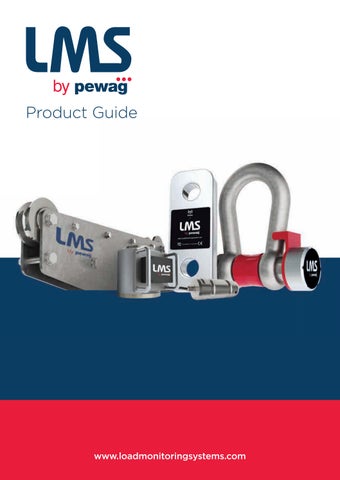
Product Guide
www.LoadMonitoringSystems.com www.loadmonitoringsystems.com
CALIBRATION & TESTING
INDUSTRY APPLICATIONS
MONITORING & MEASUREMENT
• Water weights & bags • Beam proof load • Crane/hoist loads • Bollard pull for vessels • Force calibration • Hydraulic presses • Laboratory weighing & calibration
• Wind turbine installations • Warehouse despatch • Subsea vehicle lifting • Subsea cable laying, recovery & repair • Subsea ploughs • Anchor systems • Mooring systems • Under hook crane weighing • Pipe laying ships • Structural joints • Hydraulic presses • Lifting systems • Aerospace development
• Cable tension • Towing • Mooring • Crane safe • Anchor line tension • Static wire tension • Winch load • Elevator cable • Speed • Payout distance • Jacking force • Pile force • Sheave/pulley system line tension • Container weighing • Centre of gravity weighing • Overload protection
Strength to get the job done.
2
Why choose LMS? Based in Aberdeen Scotland, Load Monitoring Systems (LMS) specialise in the design and manufacturing of load monitoring products and services, including sales and rental of load cells, winch monitoring systems and Crane Safety Instrumentation. The products are engineered to the highest standards, defined by quality, strength and reliability and used globally for a wide variety of applications, across many industry sectors including, Oil & Gas, Marine, Subsea, Decommissioning, Construction, Mining, Wind Energy, Aquaculture & Entertainment. With over 50 years’ experience in specialist load monitoring, LMS products and services are being supplied to over 45 countries and most continents, often with support from local distributors and agents. LMS has a proven track record developing a range of products and services tailored around our customer requirements and continues to build the business and extend its offering with increased rental stock, larger capacity equipment and by providing a ‘FAST-TRACK’ repair and calibration service, specifically created to support customers where turnaround time frames are critical.
We would be delighted to discuss your requirements Call: +44 (0) 1224 446100. www.loadmonitoringsystems.com lms@loadmonitoringsystems.com
We specialise in the design and manufacture, rental and sales of load monitoring equipment for industrial applications across many industry sectors worldwide.
3
Harbour Crane Load Monitoring
ASCO, an organisation with global expertise in the area of oil and gas materials and equipment management, needed to monitor crane loads in their supply base locations around the world.
Load Monitoring Systems (LMS) took on the project and developed a custom load link system. LMS manufactured Load Cells, Mantracourt’s T24 wireless telemetry instrumentation and strain gauges by industry-leading manufacturer Micro-Measurements were used. ASCO’s sites operate in extreme weather conditions and the application was a test for the reliability of all components in the system. It was installed in 2014 and continues to prove its quality with ongoing faultless service.
4
“The installation of Load Monitoring Systems load cells and Mantracourt T24 technology across our operations has helped us to accurately monitor weights whilst feeding live information back into our operational systems. The interface with our Integrated Logistics Management System, has provided us with increased efficiencies and enhanced planning capabilities. The measurements have been accurate and reliable, even in challenging conditions.” Greg Skinner, Project Manager
Mini PC running Log 100 with wireless connection
Long Range Booster
JSON output
T24
1km range
T24 Receiver with External Antenna
ASCO Wireless System UPS
Application
Solution
Key Benefits
ASCO operate cranes in supply bases across the world, from Hammerfest in Norway to Darwin in Australia. Load Monitoring Systems (LMS) used Mantracourt’s T24 wireless strain transmission module and Micro-Measurements strain gauges on their manufactured Load Cells to meet the requirements. The system has proved its quality by overcoming the challenges of the application, something the previous generation of solutions couldn’t achieve.
The system, designed, manufactured and assembled by LMS, picked up the signal from T24 transmission modules in load links and pushed it to the web as shown in the diagram above. This allowed for readings to be monitored using any cellular enabled device by accessing a dedicated web address. Overload warnings were in place, which simplified monitoring.
• Load data reviewed wirelessly from tablets anywhere in the harbour.
Challenge The nature of the application meant that large distances had to be covered reliably by the system. Signal integrity had to be sufficient for the system to continue functioning at times when the line of sight between the load links and the receivers was obstructed by the body of the ships. In addition, the application required that the data from the readings is easily visible from anywhere on the base - not just the control room. This way, supervisors would be able to monitor weights as they coordinate loading operations.
The JSON input provided by LOG100 web server is an ideal way of monitoring device readings in applications with lower levels of complexity. A link with visual the interface is automatically generated by the software. JSON packages containing the key information around a reading are also available to feed customised web interfaces. The web view can be made accessible either from the same network only, or forwarded to the internet, as was the case with Load Monitoring Systems’ project.
• Accurate measurements under a wide range of temperatures made possible by Micro-Measurements strain gauges. • Robust system that functions faultlessly under severe weather conditions. • No cabling required on cranes. Load links are powered by batteries, which only need to be replaced in six-month intervals during routine maintenance. • High signal integrity allows transfer of load data even with obstructions.
Results All technology has successfully proved itself in the face of the challenges offered by the application. The first of ASCO’s systems has now been in service since 2014 and the pilot project has been replicated in an additional three locations of the company.
5
Rentals
When there’s a need for load testing, rental is often the easiest and most cost effective solution.
Rental Equipment
Proof Load Testing Equipment
Applications
• Load Links 1Te – 500Te • Load Pin Shackle 3.25Te - 500Te • Data Logging • Load Cell Displays
• Water Bags & Test Weights
• Water Weights & Bags • Payout Distance • Towing • Container weighing • Winch Load • Crane/Hoist Loads
Lifting and positioning • Equipment: Range of Air Skates
6
Ready when you need it. Trusted Rental Partner Each rental item is fully maintained, checked and certified before leaving our facility so you can be confident it’s ready to go as soon as it arrives on location. Rental periods are flexible from a single day to longer-term hire, just give us a call to discuss your requirements and we’ll provide you with a competitive quote.
READY FOR USE
Training All equipment is supplied with relevant documentation including comprehensive operating instructions and certification. LMS can provide training at our facilities should this be a requirement. Training covers all aspects of set up and operation and comes with our own proofof-completion certificate.
7
Load Link Accurate and reliable tensile load monitoring for lifting applications. Suitable for all industry sectors including marine, offshore and subsea. Due to the robust, lightweight high tensile aluminium design these load links are Ideal for mobile applications and available as either cabled or wireless with a range of options. Retro-fit load monitoring to existing applications where shackles are already available and fits all major shackle manufacturers including Van Beest, Crosby and GN Rope.
Options Wireless &
Matched Telemetry
Internal Antenna
Displays
Cabled with 49.2ft
Data Logging
flying cable
Software Available
Rent this item
ATEX version
Specifications Overload Tested (Proof Load)
200% rated load (6.5te - 250te sizes) 150% rated load 300te and above
Minimum
5Te to 400Te
500% rated load
500Te
450% rated load
Breaking Load (MBL)
Features • Load link designs from 6.5Te to 500Te as standard other capabilities on request
Dead Load Offset
+/- 0.1mV
Accuracy
< 0.5% of applied load
Repeatability
< +/- 0.1% of applied load
Hysteresis up to FS
Minimal
Operating temperature
-20°C to +70°C
Environmental Rating
IP67
• Accuracy <0.5% of applied load
Range
800 Meters (straight line uninterrupted view)
• ATEX versions available for zones 0, 1, & 2
Transmit rate
900ms (standard)
• Subsea variants available on request
Antenna (Wireless Version)
Internal
Radio (Wireless Version)
2.4 Ghz; worldwide licence free
Cabled Version Output Signals
Analogue signals
• Designed to be rigged & operated with a Working Load Link (WLL) of the same capacity • Safety factor of 5:1
• Every unit load tested and certified
4-20mA in 2 or 3 wire output with 10-30VDC supply 0-5VDC or 0-10VDC 3-wire output with 10-30VDC supply Digital signals RS232 with a protocol of your choice with 5-20VDC supply RS485 with a protocol of your choice with 5-20VDC supply Cable Version Connection Type
Load link with plug-in socket and 15m, 4-core screened PUR cable with matched plug-in connector fitted. Other types on request.
Battery Type /
Load Cells
Lifespan
6.5Te - 2 x AAA 1.5V @ 500+ hours (continuous) 13.5Te - 85Te Load Link - 2 AA 1.5V @ 1200+ hours (continuous) 100Te - 500Te Load Link - 2 x C 1.5V @ 2000+ hours (continuous) Battery changes are reduced when device is put on sleep mode during 12 month calibration windows.
Display
2 x AA 1.5V batteries @
40 hours (continuous)
Calibration
12 months (calibration service available)
Warranty
12 months
Material Finish
Lightweight, high tensile grade aluminium, hard anodised for marine
Traceability and Safety Compliance
BS EN ISO 7500-1:2004, Machinery directive 2006/42/EC (SI 2008/1597)
environments. ATEX Options Zone 2
Standard options (wireless and cabled) - see datasheet
Zone 1
Standard options (wireless and cabled) - see datasheet
Zone 0
Stainless steel construction, cabled options – contact LMS for more details
8
www.loadmonitoringsystems.com
C A
Ø E
B
D I
H
J
G
Load Link Dimensions mm Capacity Tonne
1
3.25
6.5
13.5
17
25
35
55
85
100
150
200
250
300
400
500
A
52
60
84
84
93
127
137
163
198
236
272
331
353
398
490
540
B
151
183
238
292
302
332
386
466
518
610
695
769
829
937
1037
1137
C
31
31
32
45
50
60
70
75
104
105
136
150
175
190
198
198
D
117
133
162
182
182
206
226
286
310
350
395
419
469
517
547
607
ØE
12
20
27
40
43
55
61
75
86
100
118
135
145
158
180
190
G
58.5
66.5
81
91
91
103
113
143
155
175
197.5
209.5
234.5
258.5
273.5
303.5
Weight (kg)
0.35
0.65
1.35
2.3
3
5.7
8.25
16
23.45
36.05
59.5
89.5
123.5
167
251
311 2588
Load Link & Shackle Dimensions mm H
221
312
397
556
592
702
777
1006
1201
1435
1533
1815
1977
2183
2398
I
201
280
353
486
516
612
677
876
1051
1245
1323
1575
1717
1903
2058
2228
J
25
48.5
57.5
97
107
140
145.5
205
266.5
317.5
314
403
444
483
510.5
545.5
0.67
2.13
4.89
15.38
19.38
34.14
47.31
95.18
147.45
256.05
409.5
559.5
693.5
847
1371
1681
2.5
6
5
6
6.7
9.5
12
23
30
47
74
106.15
140.15
183.65
267.65
327.65
1
3.25
6.5
13.5
17
25
35
55
85
100
150
200
250
300
400
500
Combined Weight (kg) Kit Weight (kg) Shackle Size / Type Van Beest
G-4163
GN Rope
H9
Crosby
P-6036 H10 G2130 to G2140
Load Cell Data Logging
Displays & Portable Case
LMS-LOG100 Advanced data logging software provides real time monitoring of up to 100 load cell devices simultaneously.
Rugged case design with foam compartments to firmly hold the load link, telemetry display, spare set of batteries. Can also accommodate connecting cable for wired units and matched set of shackles.
Remotely access your data quickly and easily from a computer, tablet & smart phone via web browser. Export data in standard JSON or CSV formats with customizable reporting to suit your needs.
• Lockable case • Plastic case available for 6.5Te - 85Te • Custom transport case 100Te - 500Te
9
Load Pin Shackle Robust, compact high tensile steel design from 2Te to 2000Te. Ideal for precise tensile load monitoring for your lifting, static, pulling or weighing applications. Suitable for all industry sectors including marine, onshore, offshore and subsea. You can be confident each shackle and load pin is up to the task with the certified load test before delivery.
Options Wireless &
Matched Telemetry
Internal Antenna
Displays
Cabled with 49.2ft
Data Logging
flying cable
Software Available
Rent this item
ATEX version
J
A G F H
Standard Designs (Van Beest Shackles)
B D
Capacity Te 3.25
E
Dimensions (mm) a
b
d
e
f
g
h
j
16
19
16
26
63
43
110
75
Features • Design uses VanBeest™ Greenpin® shackles as standard, others on request
K
• Load pins from high-strength stainless steel
Weight (kg)
• Safety factor of 5:1
1.7
4.75
19
22
19
31
76
51
129
89
1.9
6.5
22
25
22
36
83
58
143
102
3.2
13.5
35
38
35
57
133
92
227
238
6.54
• Up to 12 shackles can be linked to the handheld display for individual or summed load values • Integral signal conditioning
25
45
50
45
74
178
126
300
216
14.22
• Subsea variants available on request
35
50
57
50
83
197
138
331
238
19.85
• Special design available on request
55
65
70
65
105
260
180
433
310
39.59
85
75
83
73
127
329
190
527
340
62
120
95
95
91
147
400
238
647
428
110
150
105
108
102
169
410
275
688
485
160
200
120
130
113
179
513
290
838
530
235
250
130
140
118
205
554
305
904
565
285
300
140
150
123
205
618
305
996
585
340 560
400
170
175
164
231
668
325
1114
665
500
180
185
164
256
718
350
1190
710
685
600
200
205
189
282
718
375
1243
775
880
700
210
215
204
308
718
400
1263
820
980
800
210
220
204
308
718
400
1270
820
1100
900
220
230
215
328
718
420
1296
860
1280
1000
240
240
215
349
718
420
1336
900
1460
Centralising bobbin for improved load cell accuracy
Integrated aerial for added protection
Special Designs (Crosby Shackles) Capacity (Tonne)
10
Dimensions (mm) a
b
d
e
6.5
24.6
25.4
22.4
36.6
25
44.5
51
49
73
f
Weight (kg) g
h
j
84
58
148
102
3.2
178
127
313
225
18
www.loadmonitoringsystems.com
Load Pin Accurate real-time load monitoring of any load bearing pin connection or joint. Load pins are integrated in mechanical structures and mechanisms to provide precise load monitoring accurate to 1%, safety factor of 5:1 and all proof-loaded to 150%. Used in construction, automation, marine, offshore and subsea, these pins can be designed to suit your application with capacities from 2Te to 2000Te.
Options Wireless &
Matched Telemetry
Internal Antenna
Displays
Cabled with 49.2ft
Data Logging
flying cable
Software Available
Rent this item
ATEX version
A
Features
C
• Output options include mV, mA, V, RS232 with others available (on request) • Single, dual and redundant bridge designs
D
• Standard operating temperature -20°C to +80°C
Indicate preferred side for load pin head and anti-rotation plate with enquiry.
• Plug-in connector versions available • Integral signal conditioning available • Enclosure IP67 as standard
B
• Subsea variants (on request) • Every unit load tested and certified
Each load pin will be designed and manufactured to suit your application, ensuring maximum performance and ease of installation. Detailed above are the most critical dimensions. When making an enquiry, please provide these values (A, B, C and D) along with any additional requirements/restrictions due to the application such as pin length, head size etc.
Load Pin Locking The load pin needs to be securely locked into position. This can be achieved by the following common methods: • Single anti-rotation plate • Double anti-rotation plate (both on one end or one on each end of pin) • Anti-rotation plate, split pin & washer • Anti-rotation plate and lock nut on threaded end of load pin • Anti-rotation yoke (similar to shackles), split pin & washer www.loadmonitoringsystems.com
11
Running Line Tensiometer For winch, crane, towing, laying and tensioning applications. Monitor speed, payout for wire rope, synthetic rope, dyneema, fibre optic and cable systems in marine, offshore, onshore and subsea applications. Incorporate data logging and the matched line monitor display for capacities up to 120Te.
Options Matched Telemetry
Internal Antenna
Displays
Cabled with 49.2ft
Data Logging
flying cable
Software Available
Rent this item
ATEX version
C
B
A
Wireless &
Features • 20 Running line tensiometer designs RLM Dimensions (mm)
• Line capacities up to 120Te
Rope Size
Model
A
B
C
SWL
MBL
Weight (kg)
10
1
722
250
162
9Te
18Te
21.5
13
1
722
250
162
9Te
18Te
21.5
16
1
722
250
162
9Te
18Te
21.5
19
1
722
250
162
9Te
18Te
21.5
22
1
722
250
162
9Te
18Te
21.5
25
1
722
250
162
9Te
18Te
21.5
22
2
810
270
186
22.5Te
45Te
37
25
2
810
270
186
22.5Te
45Te
37
• Simple and quick access for line/rope fitting • Marinised design ensures corrosion prevention in offshore environments
28
2
810
270
186
22.5Te
45Te
37
32
3
963
297
188
45Te
90Te
56
• Line mounted supplied with tether/swivel mount as standard with the options for bolt on feet or trunnion mount (pivot on 2 feet)
35
3
963
297
188
45Te
90Te
56
• Custom mounts available on request
38
3
963
297
188
45Te
90Te
56
40
3
963
297
188
45Te
90Te
56
42
4
1029
296
198
60Te
120Te
77
44
4
1029
296
198
60Te
120Te
77
48
4
1029
296
198
60Te
120Te
77
52
5
1250
426
185
90Te
160Te
125
56
5
1250
426
185
90Te
160Te
125
64
5
1250
426
185
90Te
160Te
125
70
6
1703
488
278
120Te
200Te
330
77
6
1703
488
278
120Te
200Te
330
88
6
1703
488
278
120Te
200Te
330
103
6
1703
488
278
120Te
200Te
330
Line Monitor Displays
• Calibrated in tonne with weight resolution accuracy available in kg, lb or kN
Matched with our running line tensiometer featuring simple to use keyboard and clear multi-digit 0.35mm LCD display.
• Wireless range of 600m+
12
• Rugged design for operation in the most extreme environments
Line Diameters from Ø10mm to Ø104mm
Use in conjunction with LMS handheld displays
• Tactile keypad • Low power consumption for long battery life www.loadmonitoringsystems.com
Compressive Load Cell Compressive load monitoring indoors, outdoors or subsea. Perfectly at home in the laboratory or hostile marine environment, the compact and robust stainless steel design can be used for weighing, force measurement and calibration. Standard capacities from 2Te to 1000Te, accuracy better than 1% and each unit proof loaded to 200% (LOLER compliant) and certified.
Options Wireless &
Matched Telemetry
Internal Antenna
Displays
Cabled with 49.2ft
Data Logging
flying cable
Software Available
Loading dia
Swivel top dia
• Cells designed to your application
• Enclosure IP67 rated
Mil spec 6 pin flange connector B.H
• Output options include mV, mA, V, RS232 with others available, on request Diameter
• Single, dual and redundant bridge designs • Extra support base flanges available on request • Plug-in connector versions available • Integral signal conditioning available • Subsea variants available on request
Supplied with domed top and spherical loading cap
Optional loading base
Base dia
Typical Load Cell Sizes Capacity (Tonne)
50
100
200
300
500
1000
Diameter (mm)
øA
75
120
125
150
200
290
Height (mm)
B
110
142
180
180
300
425
Loading Diameter (mm)
øC
60
90
110
130
170
250
øF
65
93
125
150
200
290
G
10
18
30
30
50
50
Spherical Cap Diameter (mm) Spherical Cap Height (mm)
Cabled versions with 10m glanded exit flying cable as standard. Other lengths available on request.
Optional swivel top
Cable entry, 10M 7mm OD to mil spec connector
Height
• Safety factor of 5:1 • Operating temperature -20°C to +80°C as standard
ATEX version
S.T.H
Features
Rent this item
These sizes are a guide, larger or smaller sizes are available. We can design and manufacture a load cell to suit your exact application so that you achieve the maximum performance.
New Centre of Gravity Feature The Centre of Gravity (COG) function found within T24LOG100 gives you the tools to quickly calculate and visualise centre of gravity from up to eight sources of weight data. Choose your weight data, specify the X and Y co-ordinates and let LOG100 do the work to calculate and display the position of COG. www.loadmonitoringsystems.com
13
Digital Pad Eye Tester Allows you to proof test your pad eyes to ensure a safe lift Lightweight, portable tool for testing pad eyes, lifting lugs, and eye bolts. It can be used upright, inverted, or in a horizontal plane. Models are available up to 10Te & 30Te models proof test capability. Equipped with an adjustable clevis height and Digital Mounted Display.
Our Unique Digital Pad Eye Tester There are many pad eye testers in the market however the main unique difference with LMS pad eye tester is the on board ‘Digital display’ (Tonnes, US Ton, Lbs, Kg) and the ability to transmit the information wirelessly to a Hand held Display, a Laptop or PLC and finally the Bluetooth feature for use with a Mobile Phone, Tablet or Laptop.
Applications Proof testing pad eyes, lifting lugs, and eye bolts. Can be used upright as pictured, inverted, or in a horizontal plane
Features • Light weight and portable • Assist handles on two sides • Large dial capacity readout • Xylan coated finish • 10ft. polyurethane hose with quick couplers • Lightweight two-speed hand pump with locking handle • Proof tested and calibrated • Carrying case
Display Options • Standard – On Board Digital Display • Bluetooth – Mobile & Table App • Wireless – Laptop or Handheld Display • Data Logging – Laptop
14
www.loadmonitoringsystems.com
Eye Pad Tester TECHNICAL INFORMATION Padeye Tester Dimensions (mm) SWL
A
B
C
D
øE
F
G
H
I
J
øK
Weight
10te
124.5
258.5
188.5
99.5
70.5
77
78.5
471
120
52
33
11.5kg
30te
203
330
188.5
99.5
115
96
100
767
234
72
53
56kg
F
E
D
H C
L
I
J ØK G A B Spec
Features
Battery Type & Lifespan - 8 x AA 1.5V @ 80 hours +
Digital Mounted Display
Safety Factor - 4:1
Peak Value
IP Rating - IP65
F
E
Zero Function
Stroke - Variable with adjustable threaded length
Overload Warning
Proof loaded - 125%
Displays readings in US TN, Tonnes, kg & lb K Lightweight with Handles for Easy Transport
Calibration - <1% of FSD, valid for 12 Months Warranty - 12 Months
Bluetooth Signal
Five Pins and Collar Sets -
D
C
10te Tester
30te Tester
3.25te
9.5te
Radio Wireless Signal Transmitter with a range of up to 800m Hydraulic High pressure hoses
4.75te
12te
Hydraulic Hand pump
6.5te
13te
Threaded rod to allow varying heights
8.5te H
17te
Additional threaded rod to increase the height
10te
30te
Hose nozzle equipped with quick coupling that can be detatched from the Padeye tester for transport Easily assembled and disassembled for transport and replacing parts
L I J
G A B
15
Air Skates Air skates are an innovative and cost-effective solution for moving heavy loads Air skates are robust, low profile, high capacity load-moving modules used in sets of four or more to enable large or heavy objects to be moved with ease.
Versatility and Efficiency
Features
Combine simplicity of operation with extreme versatility. Load movement is easy, exceptionally smooth, omnidirectional and can be performed anywhere in the work environment where there is an adequate floor surface. Operation in tight spaces is a breeze.
• Working load capacities of up to 100 tonnes and higher
Load Module™ Aero-Caster® distribute the load weight over a greater surface than with rollers or wheels, spreading any stress evenly on the floor. This eliminates damage to the floor and the need for expensive tracks, reinforced floors and building structures.
• Easy to set up with quick release couplings
Load Modules™ are easily portable and can be positioned under the load according to weight distribution on load support points. This minimizes stress on the load structure.
• Move loads in restricted areas where forklifts/cranes cannot reach
• Powered by a regular workshop air supply of 5 to 7 bar • Easy to use and cost effective • Low floor pressures • Modular capability giving ultimate versatility
How they Work The air skates are connected with a hose manifold and supplied with compressed air. With the air turned on, the flow to each air skate is regulated to accommodate the load and floor conditions, allowing the load to be lifted clear of the floor.
16
• Accurate and repeatable positioning with omni-directional capability • Low profile skate modules for ease of location underneath loads
www.loadmonitoringsystems.com
Modular Air Bearing System (MLS) TECHNICAL INFORMATION Capacity per set of 42
Air consumption3
A
B
C
D
E5
kg
lbs
Nl/min
SCFM
mm
mm
mm
in
in
MLS 412X-S-A
7000
15400
1120
39
304
31/514
15
1/2
1
MLS 415X-S-A
10000
22000
2200
77
380
31/514
20
1/2
1
MLS 418X-S-A
11200
24200
2600
92
457
58
20
3/4
1
MLS 421X-S-A
14000
31000
3000
106
534
58
25
3/4
1
MLS 427X-S-A
24000
53000
3400
120
684
65
35
3/4
1 1/2
MLS 436X-S-A
44000
97000
4000
141
914
71
50
3/4
1 1/2
MLS 418X-H-A
20000
44000
4600
162
457
58
20
3/4
1
MLS 421X-H-A
28000
62000
5200
184
534
58
25
3/4
1 1/2
MLS 427X-H-A
48000
106000
6000
212
684
65
35
3/4
1 1/2
MLS 436X-H-A
80000
176000
7000
247
914
71
50
1
1 1/2
MLS 442X-H-A
120000
265000
7500
262
1070
71
65
1
2
MLS 448X-H-A
160000
353000
8000
282
1220
71
75
1
2
MLS 460X-H-A
240000
528000
11000
388
1505
71
75
1
2
Type 1
Capacity per set of 62
Air consumption3
A
B
C
D
E5
kg
lbs
Nl/min
SCFM
mm
mm
mm
in
in
MLS 612X-S-A
10500
23000
1680
59
304
31/514
15
1/2
1
MLS 615X-S-A
15000
33000
3300
116
380
31/514
20
1/2
1 1 1/2
Type 1
MLS 618X-S-A
16800
37000
3600
126
457
58
20
3/4
MLS 621X-S-A
21000
46000
4500
158
534
58
25
3/4
1 1/2
MLS 627X-S-A
36000
79000
5100
179
684
65
35
3/4
1 1/2
MLS 636X-S-A
66000
145000
6000
210
914
71
50
3/4
1 1/2
MLS 618X-H-A
30000
66000
6300
221
457
58
20
3/4
1 1/2
MLS 621X-H-A
42000
92000
7800
273
534
58
25
3/4
1 1/2
MLS 627X-H-A
72000
158000
9000
315
684
65
35
3/4
1 1/2
MLS 636X-H-A
120000
264000
10500
368
914
71
50
1
2
MLS 642X-H-A
180000
396000
11100
389
1070
71
65
1
2
MLS 648X-H-A
240000
529000
12000
420
1220
71
75
1
2
MLS 660X-H-A
360000
792000
16500
582
1500
71
75
1
2
1) A’ refers to standard plastic support bars under the control unit. Other features are available under ‘Options’ below. 2) The modules must be placed under the load so that each one sees no more than one quarter of the full system capacity. 3) These figures refer to good floor conditions, i.e. power-trowelled andsealed concrete surfaces. 4) Cast aluminium/Extruded aluminium construction. 5) Supply hose ID and shut-off-valve thread size.
The Modular Air Bearing System includes: •
4 air bearing modules
•
4 interconnection hoses with quick release
•
couplings
•
Control unit equipped with pressure
•
Regulator and gauge for each module,
•
Supply pressure gauge and plastic support bars
•
30 m supply hose including shut-off valve
•
Operating instructions
A i r b e a r i n g mo d u l e C
B
A
A
C
D
D
= N o mi n a l l i f t i n g h e i g h t
= I n t e r n a l d i a me t e r
In te r c o n n e c tio n h o s e L = 4m In te r c o n n e c tio n h o s e L = 6 m
Q u ic k r e le a s e c o u p lin g C o n tr o l u n it
S h u t- o ff v a lv e
Optional: •
Remote control unit
•
Control unit for six-module system
•
Control unit equipped with assembly
•
Brackets or ball casters
•
8 m or 10 m interconnection hose
•
50 m supply hose including shut-off valve
•
Outlets for air jacks and external drive units
E
E = I n t e r n a l d i a me t e r C o mp r e s s e d a i r s u p p l y 6 00 k P a = 6 b a r ( 90 p s i )
17
COMBO-Kits Portable, flexible & ready right out of the box. When you need a load monitoring kit onsite that can be tailored for low head height situations.
Options Wireless &
Matched Telemetry
Internal Antenna
Displays
Cabled with 49.2ft
Data Logging
flying cable
Software Available
Rent this item
ATEX version
Current Range
Features
3.25 Te Load Cell COMBO Kit. 4.75 Te Load Cell COMBO Kit. 6.5 Te Load Cell COMBO Kit. 13.5 Te Load Cell COMBO Kit. 17 Te Load Cell COMBO Kit.
• All of the equipment supplied in a custom transport case.
Combo-Kit Contains
• Only one wireless handset is required.
• Rugged case design with foam compartments to firmly hold the load link, telemetry display.
Optional Accessories
• 1 x T24-HK-S All-in-one Handheld Display (Can operate with both Load Link or Load Pin).
• Wireless Data Logging Kit. (Including Wireless Base station receiver and Logging Software)
• 1 x Aluminium Load Link complete with calibration certificate.
• Load Link concept can be used for greater accuracy with adequate head space. • Load Shackle concept can be used when lower head space is required.
• 2 x Safety Bow Shackles. • 1 x Shackle Load PIN complete with calibration certificate. • 1 x centralising Bobbin. • Spare Battery Set.
18
www.loadmonitoringsystems.com
Head Height Comparison (inch) Dimensions (inch) Capacity Ton
3.25
4.75
6.5
13.5
17
Load Link
12.3
13.6
15.6
21.9
23.3
Load Pin Shackle
4.3
5.1
5.7
8.9
9.8
Head Height
Head Height
Load Link Dimensions (inch) Dimensions (inch) Capacity Ton
A
B
C
D
Eø
G
Weight
H (Head Height)
I
J
Combined Weight
3.25
2.4
7.2
1.2
5.2
0.8
2.6
1.43
12.3
11.0
1.9
4.69
4.75
2.4
7.2
1.2
5.2
0.9
2.6
1.43
13.6
12.1
2.4
6.63
6.5
3.3
9.4
1.3
6.4
1.1
3.2
2.98
15.6
13.9
2.3
10.78
13.5
3.3
11.5
1.8
7.2
1.6
3.6
5.07
21.9
19.1
3.8
33.90
17
3.7
11.9
2.0
7.2
1.7
3.6
6.61
23.3
20.3
4.2
42.71
C A
Ø E
B
D I
H
J
G
Load Pin Shackle (inch) Dimensions (inch) Capacity Te
A
B
D
E
F
G
H (Head Height)
J
3.25
0.6
0.7
0.6
1.1
2.5
1.7
4.3
3.0
Weight 1.98
4.75
0.7
0.9
0.7
1.2
3.0
2.0
5.1
3.5
2.60
6.5
0.9
1.0
0.9
1.4
3.3
2.3
5.7
4.0
3.90
13.5
1.4
1.5
1.4
2.2
5.2
3.6
8.9
6.4
14.41
17
1.5
1.7
1.5
2.4
5.7
3.9
9.8
6.9
18.05
J
A G F H
B D
E
D
19
Load Cell Data Logging LMS-LOG100 Advanced data logging software provides real-time monitoring of up to 100 load cell devices simultaneously. Quick and easy to remotely access your data on computer, tablet & smart phone via web browser. Export data in standard JSON or CSV formats with customisable reporting to suit your needs.
Options Wireless &
Matched Telemetry
Internal Antenna
Displays
Cabled with 49.2ft
Data Logging
flying cable
Software Available
Rent this item
ATEX version
How it Works Product Support
Load Shackle
Features • Log data at timed intervals, manually (on demand), on entering & exiting a pre-set overload/underload, during an overload/ underload. • Visual display and audible alarm indicators for overload/underload conditions as well as loss of communication • Display live data readings on a visual graphic of your application (picture/ drawing/schematic) • Display numeric and graph data
Base Station Load Link
• Units of measurement selectable to match load cell • Built in web server • Defined algorithms and maths functions
Internet
• Works with USB base station Line Rider Tensiometer
• Windows 8, 7, Vista & XP compatible • Supplied pre-installed on computer with or without display screen • System can be installed on existing computers
Compressive Load Cell
Use in conjunction with LMS handheld displays
Load Pin
20
www.loadmonitoringsystems.com
LMS-QV Quick View for Load Cells This software allows you to quickly detect, pair, view and log data from a LMS load cell device. System requirements: Windows 8, 7, Vista or XP & USB base station
Features • Detect or pair to a load cell device • View the acquired data on a large simulated LED display • Export the data to a CSV file • Supplied pre-installed on computer with or without display screen • System can be installed on existing computers • Quick & easy to operate
Product Support
Load Shackle
Load Link
Line Rider
Compressive
Tensiometer
Load Cell
Load Pin
LMS-Toolkit Toolkit for Load Cells This software allows you to quickly and easily configure, test communication and calibrate LMS wireless load cell devices. System requirements: Windows 8, 7, Vista or XP & USB base station
Features • View and alter load cell device parameters • Execute commands • Save and restore configuration data to files • Check radio link quality • Calibrate load cell modules • Perform simple data logging • Supplied pre-installed on computer with or without display screen • System can be installed on existing computers
Product Support
Load Shackle
Load Link
Line Rider
Compressive
Tensiometer
Load Cell
Load Pin
21
Design, Testing, Repair and Calibration Benefit from our years of experience. We can design, manufacture, service and test load monitoring equipment.
Load Cell Calibration & Testing LMS have multiple test beds in-house, that enable us to provide a quick and effective repair and calibration service. Our technical experts can carry out inspections and repairs, upgrades and conversions, scheduled or project calibration and certification and bespoke reporting. We can also provide stress analysis and measurement for client products whether in-service or in the laboratory.
Key facilities include: • Vertical & horizontal • 50 Te and 100Te test rigs
100Te Tensile Test Rig Description
100te vertical digital test rig
Safe Working Load (SWL)
100 metric tonne (TE)
Mode of Operation
Tensile
• Comprehensive data logging
Category
Class 1 test bed
• A dedicated strain gauge area
Certification Standard
ISO 7500-1:2004 (E)
• Mechanical technicians • Electrical technicians • In-house electronics & machining
500Te test bed capabilities
22
Accuracy
+/- 1%
Repeatability
+/- 0.2%
Resolution
User display: 1 kg res. Large display: 100kg res.
Logging Rate:
Up to 200 readings per second
Method of Measurement
Whetstone bridge on double strain gauged column
T24-HK-S All-in-one Handheld Display Built for tough environments – robust, non-slip and durable. This next-generation handheld display eliminates the need for multiple handsets.
The T24-HK-S seamlessly connects with all LMS wireless load links, load pin shackles, RLMs, and compressive load cells.
Featuring large, LED backlit display for fast, reliable readings in any lighting. With rugged, textured casing for harsh industrial and offshore environments.
Wireless
T24-HK-S Features • One handset does it all compatible with all LMS load monitoring products • Rugged IP67-rated enclosure – dust-proof and waterproof • Textured, non-slip grip – better handling in the field • Bright LED backlight – clear, easyto-read display in any lighting • Multi-use - connect up to 12 devices • Ready to use – pre-configured and calibrated
Dimensions 93mm
40mm
• Real-time data – instant access for faster decision-making • User-friendly – quick, accurate readings • Long range – 800m wireless connectivity • Long battery life – up to 35 hours on 2 x AA batteries • Wide temperature range – from -10°C to +50°C
171mm
MENU OK
• Humidity resistant – works in environments with up to 95% humidity
www.loadmonitoringsystems.com
23
Get stressfree in less than 24hrs. FAST-TRACK SERVICE AVAILABLE CALL FOR DETAILS
We understand that sometimes calibrations or essential repairs become a priority issue and equipment needs to be back in service as quickly as possible. FAST-TRACK repair and calibration provides a 24hr priority service designed to support customers when they need it most. Call or visit www.LoadMonitoringSystems.com to find out more.
Services
Servicing
Certification & Compliance
• Calibration
We can service all types of load cell products not just our own.
Compliance with all major standards including those for LOLER, BSI, DNV, ASME, CE, EMC, FCC and Machinery Directive.
• Repair • Inspection • Non-destructive testing (including overload and proof-load) • Certification • New electronics for existing/OEM products • Analogue and digital output module upgrades • Bespoke test reports • Call-out service for testing at site • Load cell design development service
Page
Revision
• Load links CALIBRATION CERTIFICATE
• Load shackles
No
Date
1
16/07/19
1 of 3
Document LMS-For-448
• Load pins • Compressive load cells
Calibration Certificate :
LMS-CAL-19-614
• Running line tensiometers
Customer :
Alatas
• Load washers
Description: Serial Number: Capacity / Range: Unit of Measurement:
• Shear beam load cells • Displays
Load Link LMS-L-6.5-047 6.5te Tonnes
Transmitter ID: Temperature: Job Type: Force Applied:
FDD535 Ambient Sale Tension
Equipment : The Accuracy of the Equipment used is traceable to BS EN ISO 376:2011 via UKAS LAB 0478 Calibration: Standard calibration in accordance with BS EN ISO 7500-1:2018 Test Bed Reference: 6.5te High Accuracy Load Cell, S/N 66044, Cert # M20140
• Machining service for bespoke designs
Max Error %
% Deviation of Reading 0.1 0.1 0.1 0.1 0.1 0.0 0.0 0.0 0.0 0.0 0.0
1.0
2.0
3.0
Tonnes
4.0
5.0
6.0
7.0
Av. Reading Tonnes 0.000 1.300 2.599 3.898 5.198 6.495
Max Error Tonnes 0.000 0.001 0.001 0.002 0.002 0.005
Calibration Performance: <1% of Reading
Calibration Data Applied tonnes 0.000 1.300 2.600 3.900 5.200 6.500
Reading #1 Tonnes 0.000 1.299 2.599 3.898 5.198 6.495
Certified by: Keith Milne
24
Reading #2 Tonnes 0.000 1.300 2.599 3.898 5.198 6.496
Reading #3 Tonnes 0.000 1.300 2.599 3.899 5.198 6.495
Signed:
Max Tonnes 0.000 1.300 2.599 3.899 5.198 6.496
Min Tonnes 0.000 1.299 2.599 3.898 5.198 6.495
3
Date:
Max Error % 0.0 0.1 0.0 0.1 0.0 0.1
23/08/2019
Part of the pewag UK Group
Authorised Partners
Modular air bearing systems
Crane SLI equipment
Air skates and load moving systems
Machine skates and roller moving equipment
25
26
Strength to get the job done. 27
A92
Strength to get the job done.
Ellon Rd
Claymore Dr
HOUSE
m
or
Dr
eD r
Exploratio n
Claymore Dr
Ellon Rd A92
Claymo re Dr
Load Monitoring Systems LMS House, Aberdeen Energy Park, Claymore Drive, Aberdeen, AB23 8GD. Office: +44 (0) 1224 446100
Cl
The
Pkw y
To Ell o To Pa n Rd rkway East
LMS by pewag_Brochure_V7
A92
Ello
nR d
Email: lms@loadmonitoringsystems.com
www.loadmonitoringsystems.com
ay