17 minute read
Comparative Study of Miscible Flooding in سدنهلماروـــتكدـلا

Comparative Study of Miscible Flooding in Compositional Graded Reservoir System
By
Advertisement
Mohammad Sohrab Hossain, SPE, Norwegian University of Science and Technology (NTNU), Trondheim, Norway
Abstract
Miscible gas injection in near critical oil or volatile oil reservoir improves the recovery due to interfacial tension effects and better microscopic displacement efficiency compared to immiscible water injection. In a graded undersaturated gas-oil fluid system, all fluids are initially first contact miscible with neighboring fluids throughout the reservoir if full- pressure maintenance is supported by injection process. Smorbukk south is characterized as a compositionally graded gas condensate and volatile oil reservoir which lies near the critical region in the phase diagram. Compositional graded reservoir systems exhibit significant variation in the minimum miscible pressure (MMP). MMP variations with depth pose a challenge in selecting reservoir recovery technique to maximize the ultimate recovery. This paper deals with different scenarios of miscible flooding and compares the results with immiscible flooding for a 3-D homogeneous reservoir system. Here, MMP, determined by different injection gases, can develop far below the saturation pressure. If the injectant is CO2 or sufficiently enriched with intermediate components, the condensing and vaporizing (C/V) mechanism was developed throughout the reservoir. Dipping effects and placement of injector –producer were studied here and was found that updip formation gives highest recovery. Various injection schemes (i.e. Separator Gas and CO2) were studied in miscible flooding scenarios. The results of gas alternating gas (GAG) were compared with the water alternating gas (WAG) method and GAG was found to be the best alternative.
Introduction
A significant amount of hydrocarbon reserves are found is gas/condensate carrying formation. Rich gas condensate region may result in significant loss of heavy ends owing to liquid drop out below the dewpoint pressure and resulting in low recovery. Miscible flooding i.e. Gas cycling / injection schemes are often applied to increase condensate recovery by vaporizing the heavier components (C4+). Miscible flooding techniques were successfully deployed in gas and oil reservoirs nearly half century ago. Usually all miscible techniques are applied in the secondary or tertiary recovery process. Miscibility occurs when the injectant gases are introduced to the reservoir above the reservoir fluid’s dew point and maintain the reservoir pressure above it either by full or partial pressure support. If reservoir pressure drops below the dew point then retrograde condensation occurs and recovery drops sharply. Success of gas injection depends on many parameters varying from reservoir geology, rock properties (wettability) to fluid systems-reservoir fluid and injectant. Compositional graded reservoirs are natural phenomena which occur due to i.e.vertical thermal diffusion, chemical equilibrium and gravity effect. Compositional variation with depth occurs mainly due to biodegradation, solid precipitation in more permeable layer after migration from single or multiple source rocks. These reservoirs can be modeled by isothermal gravity/ chemical equilibrium (GCE) model by neglecting thermal diffusion or thermal convection. Chaback[1] states that thermal diffusion effects are small relative to gravity/chemical effects in the vicinity of a critical point. This paper investigates the effects various injectants, injector and producer placement, dipping of the reservoir and different injection schemes in oil recovery. Separator gas was used as an injectant in the base model. Later on CO2was used as different injectant and cyclic injection of separator gas with CO2 (gas alternating gas, GAG) and water alternating gas (WAG) were also studied. The results were compared with the base case. For miscibility, accurate determination of MMP is very important and
showed that MMP can be developed far below the saturation pressure if the injectant is sufficiently rich with intermediate components or CO2.
Model Description
Reservoir Model
In this study, a 1D reservoir model was taken with 5000×1×1 gridding. The dimension of the reservoir was 2000×3280.01×10 ft. and reservoir fluid composition was varied in the x direction with each grid. This gridding system was modified into 3D system by10×10×50 grids with dimension 2000×3280.01×50 ft. Fluid was assumed compositionally varying with depth i.e. Z direction. The layers in the X-Y plane parallel to each other were with good communication. There was no seal or fault considered in this study. All the layers were grouped in four categories. In X-Y plane, first 15 layers permeability 335, next 15 layers permeability 200, next 10 layers permeability 600 and last 10 layers permeability 700 mD were assumed. Table 1 shows the dimension of the layers and their properties. In this study one injector and one producer model was used to study the effect of the injectants.
Fluid Model
The 15 components EOS model pseudoized to 9 components following the techniques stated by Hearn and Whitson [2 ] was given for this study. But in this study, fluid composition was assumed graded in z direction and original gridding in X direction were truncated from 5000 to 50 grids in Z direction. Each new grid composition was calculated by averaging the truncated amount of grids/ cells. Thus fifty compositions were created for fifty layers in the Z direction. Table 2 shows the fluid components and values of different parameters used in the calculation. The composition of the Separator gas was used as an injectant in the base model is given in the Table 3.
Minimum Miscibility Pressure Determination
Oil recovery by gas injection depends on the minimum miscibility pressure. Minimum miscibility pressure is the lowest pressure at which inject gas becomes miscible with reservoir fluid. Minimum miscibility condition of pressure was computed numerically by isothermal gravity-chemical equilibrium gradient method with robust multicellular MMP- algorithm in PVT package [3]. The reservoir fluid model was initialized with 12,205 ft. depth with 5700 psi initial pressure and 285.5 oF temperature.The Soave Redlich Kwong (SRK) type EOS was used for PVT modeling for Smørbruk fluid. For a given depth, composition of the fluid, reservoir pressure and temperature were given and Phazecom calculated the saturation pressure. The algorithm in PVT package calculated the MMP at this depth with given injection gas. In this study, MMP was calculated by separator gas and CO2 with reservoir fluid varying composition with depth and plotted in Figure 1. Above the gas oil contact (GOC) saturation pressure (Psat) and MMP are same for separator gas but in oil region MMP varied significantly from saturation pressure (Psat). CO2 MMP is much lower than the saturation pressure (Psat) both in gas and oil zone. At very high depth, CO2 MMP increases slightly than saturated pressure. In general CO2 MMP is much lower than separator gas MMP.
Case Studies and Results
Injectants at MMP contacts with the reservoir oil and intermediate components transfer from reservoir oil to injectant. As the injectants moves forward it contacts with fresh oil and getting enricher with intermediate components. After multiple contacts, injectant becomes more oil like and mixes with oil and thus creates a slug or mix zone in the front. This is known as VG mechanism. On the tail side of the slug, richer injectants drop out the intermediate component and make the oil lighter and condensing mechanism developed[4]. The Condensing and Vaporizing mechanism is developed by diffusion process which is solely controlled by chemical potential, fugacity and mixture properties. The miscibility conditions based on the traditional vaporizing gas drive (VGD) mechanism over predicts the condition of miscibility. If injecting gas is miscible with the reservoir fluid by maintaining partial or full pressure support throughout the reservoir life that theoretically yields almost 100% recoveries if there were no other constraints exist from reservoir point of view[5].Different scenarios of injection cases were analyzed by commercial software SENSOR[6] . SENSOR based findings are discussed below:
Effect of Injectants:
In miscible type flooding, different injectants showed different impacts on the total recovery. Separator gas and CO2 were injected in the reservoir just above the MMP, separator gas yields with highest recovery. To understand the effectiveness of the miscible flooding, their results were compared with immiscible flooding like- water injection and plotted in figure 2. Separator gas gave the highest recovery (96.5%) because above GOC MMP was same as the saturation pressure or slightly higher. But for CO2, MMP was much lower than the saturation pressure, causes lower recovery (83.1%). On the other hand if the miscible process recovery was compared with immiscible process i.e. water, miscible process has
higher recovery than water injection (63.01%). Daily oil production with time was plotted and shown in figure 3. From the figure 3, daily oil production suffered after 500 days with all injection techniques. In water injection case, oil production was high in the early days (around 250 days) and reduced to almost zero after 500 days. Separator gas and CO2 followed almost the same pattern, where production was increased up to 125 days and start declining the production gradually. CO2 and Separator gas almost seized production after 1500 and 2000 days respectively. Gas oil ratio (GOR) was plotted against time with daily production rate, shown in figure 4. After 1000 days, GOR for CO2 and separator gas increased which suggests that evaporation from reservoir fluid to CO2 and separator gases were getting lesser and lesser or gases established a channeling through reservoir formation is hard to answer. To understand the sweep efficiency, Saturation maps of Gas and Oil are given at 1000 days for grid block J5 shown in figure 5 and 6 for separator gas.
Injector Placements:
Injector placement thought to be a big issue in the ultimate oil recovery was studied here. Previously, injector was placed at the top of the reservoir in one end and producer was placed at the bottom in other end. In this study, two more injector positions were considered- middle (1,1,25) and bottom (1,1,50). Placement of the injector varies the injectant flow path which affects the sweep efficiency. In this study, ultimate recovery did not show any big change with injector placements. With injector placed in the middle of z direction, ultimate recovery with separator gas, CO2 and water was 96.43%, 83.27 % and 62.87 % respectively. This is shown in figure 7 and daily production profile was same as the injector at the top was shown earlier in figure 2.
WAG and GAG:
Immiscible flooding has lower recovery than miscible flooding but it has better macroscopic sweep efficiency. Miscible flooding has better microscopic efficiency but poor macroscopic efficiency due to higher mobility ratio. Separator gas is very often unavailable due to economic reason in a producing field. Here WAG and GAG schemes were studied. In WAG process water was used as alternating injectant for separator gas and CO2 injection. Another study was carried out with CO2 as an alternative to separator gas (GAG) with same rate and cycle time. The results were presented in figure 8 which showed that separator gas WAG gives 71.64%, CO2 WAG process gives 66.25% and GAG process gives 89.52 %. GAG process recovery decrease from pure separator gas recovery by 6 to 7 %. Cost of lean or separator gas, availability of other source of gases and economy play a key role to choose the injection scheme. The average reservoir pressure for WAG and GAG cycles were plotted with time in figure 9. In WAG case, pressure is around 6000 psi and GAG case it was just above the initial pressure of the reservoir. Variation of average pressure in WAG indicated the cycles of water injection. But in GAG case, a miscible zone is created in front of the injectant which swept the reservoir fluid resulted better recovery.
Dipping Effect:
Dipping effect was also studied in miscible flooding. In this study reservoir was dipped arbitrarily at +/ -10 degree. After that different injectants i.e. separator gas, CO2 and water was injected with keeping the other reservoir parameters constant. Figure 10 and 11 show the recovery of the updip and downdip reservoir with different injectants. Ultimate recoveries for up dip reservoir with separator gas, water and CO2 were 96.88%, 63.54% and 84.73 %. On the other hand, down dip reservoir ultimate recoveries were 84.4%, 63.54% and 81.78% with separator gas, CO2 and water respectively. From the figures 10 to 12, down dip reservoir yields less recovery than up dip reservoir for separator gas and CO2. But for water injection in up dip and down dip reservoir give the same recovery. The difference in recovery in down dip reservoirs for miscible cases occur due to gravity forces dominates over viscous force in macroscopic level in this dip angles. In order to understand dipping effect on CO2 and Separator gas , saturation plot of oil and gas was created at 1000 and 2000 days. In down dip cases, gravity forces are acting with the viscous forces to reduce the sweep efficiency. So the recoveries in the downdip are always low and verified Singh’s claims[7] .
Sensitivity Analysis
The sensitivity analyses in few parameters like injection pressure and vertical-horizontal permeability ratios were done in this study.
Injection Pressure:
Sensitivity of injection pressure variation was done by commercial model integrator and optimizer[8] with SENSOR model.
Injection pressure in miscible cases was chosen higher than the highest MMP value so that the reservoir does not go below to the saturated region at any grid with depth. Here, effect of injection pressure was studied and injection pressure was chosen higher than the higher and lower values of MMP in order to get full miscibility throughout the entire life cycle of the reservoir. Reservoir initial pressure was 5700 psi and around 4.5 pore volume (PV) separator gas was injected. Results are shown in Table 3. From the result, recoveries at different injection pressures are same i.e. 95.5%. This is because of creating a slug zone around the injection layers which pushes the liquid and gives a piston like displacement with same sweep efficiency.
Vertical/Horizontal Permeability Ratio
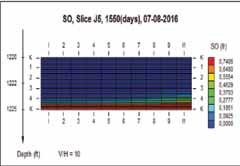
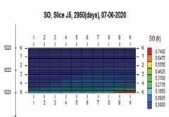
Effect Vertical and Horizontal permeability ratio on Oil recovery was studied in this study also. Vertical permeability was changed from 300 mD to 30, 3 and 0.1 mD. In all cases, oil recovery was same at the end of reservoir life. To understand the effect of vertical and horizontal permeability ratio, gas and oil saturation maps are plotted in figures 13 to 20. For lower ratio of kV/ KH, saturation of oil and gas is higher than that of higher KV/KH ratio values. But ultimate recovery of oil is same because of high flash by injectant gas. Similar study was done by Singh (2009) and suggests that for leanest condensate gas, oil recovery is almost independent of permeability distribution.[7]
Conclusions
The 3D compositionally graded reservoir model deals with wide varieties of EOR scenarios and studied by reservoir simulation. According to the results of simulation, this paper leads to following conclusions: 1.MMPs can develop below the saturation pressure depending on the composition of the injectants (CO2).
Lower MMP does not give better option in miscible gas cycling process. As ultimate recovery does not depends only on MMP but also depends on reservoir matrix, vaporization process, gravity, fluid type and its properties. 2.Injectant composition has a very high impact on oil recovery in miscible process. Separator gas always gives more than 95% oil recovery whereas CO2 miscible gas injection gives 85% oil recovery. Both miscible recoveries are higher than the immiscible water recovery (65%). 3.The CO2 GAG process gives better recovery (89%) over
WAG process recovery (i.e. Separator gas WAG 71.64 % and CO2 WAG 66.25 %). Though CO2 in GAG process recovery was offset by 6 to 7% than that of lean gas or separator gas. 4.Well placement has literally no or little effect on the oil recovery in this model for gas condensate reservoirs. But dipping angle has a considerable effect in the recovery.
Up dip injection gave better recovery in miscible flooding for this model because gravity played a positive role here. 5.Injection pressure above MMP did not have any effect on ultimate oil recovery in critical oil reservoir like Smorbukk in this study. But if the injection was done below the MMP then recovery would be reduced significantly. 6.Permeability ratio variation in vertical to horizontal direction did not show any change in oil recovery. In general for lean gas condensate system, condensate recovery is almost independent of permeability ratio variation was showed by Singh [7] and this is also verified here.
Acknowledgement
The author likes to express his sincere gratitude to Dr. Lars Hoier from Statoil ASA and NTNU for his encouragement and support in conducting the work to publish this paper. The author also likes to acknowledge the support given by petroleum engineering department at NTNU and Statoil for this study. The author also expresses his special thanks to Professor Golan and Professor Curtis for their comments.
REFERENCES
1. Chaback, J.J: “ Discussion of Treatment of Variations of Composition with Depth in Gas-Condensate
Reservoirs”,SPERE, Feb. 1992,157 - 158 2. Hearn, C.L. and Whitson, C. H.: “ Evaluating Miscible and Immiscible Gas Injection in Safah Field Oman” paper
SPE 29115 presented at the 1995 13th SPE symposium on
Reservoir Simulation, San Antonio, Feb. 12 - 15 3. PhazeComp, Zick Technologies (www.zicktech.com) 4. Zick, A.A.: “A Combined Condensing / Vaporizing
Mechanism in the Displacement of Oil by Enriched Gases,” paper SPE 15493 presented at the SPE Annual Technical
Conference and Exhibition, New Orleans, 5 - 8 October, 1986. 5. Høier, Lars and Whitson, Curtis H.:”Miscibility Variation in Compositionally Grading Reservoirs,” paper SPE 69840 , presented at the SPE Annual Technical Conference and
Exhibition, New Orleans, 27 - 30 September,1998. 6. SENSOR, Coats Engineering ( www.coatsengineering.com) 7. Singh,Kameshwar : “Gas Injection IOR for Widely Varying
Initial Compositions” paper SPE 120743 presented at the
SPE EUROPEC/EAGE annual conference and exhibition,
Amsterdam, The Netherlands, 8 -11 June, 2009 8. PIPEIT, PERA AS (www.pera.no)
Table 1: Model reservoir properties
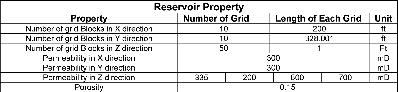
Table 2: Composition and different parameters
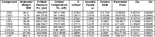
Table 3: Injectant gas composition Table 4: Sensitivity Analysis for Injection pressure
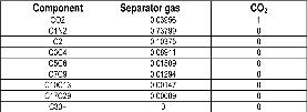
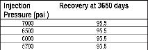
Figure 1: MMP variation with depth for compositional graded reservoir Figure 2: Oil recovery with different injectants over time, injector position at the top
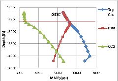
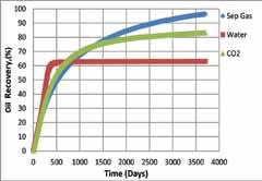
Figure 3: Daily oil production with different injection scheme with injector at top Figure 6: Oil saturation after 1000 days for J5 block
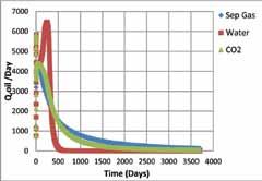
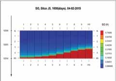
Figure 4: Oil rate and GOR change with time Figure 7: Oil recovery with different injectants over time, injector position:- middle
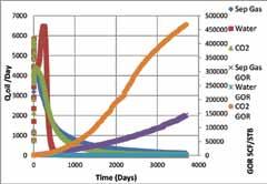
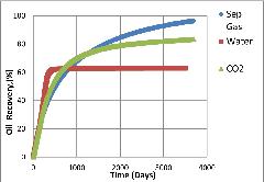
Figure 5: Gas saturation after 1000 days for J5 block Figure 8: Oil recovery with different WAG and GAG injection
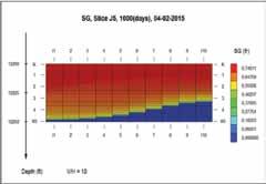
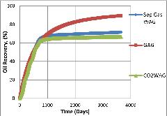

Figure 9: Average reservoir pressure in WAG and GAG Figure 12: Recovery of separator gas and CO2 in up dip and down dip
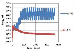
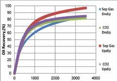
Figure 10: Updip reservoir oil recovery with time Figure 13: Gas saturation in 1550 days for KV/Kh ratio 0.0003
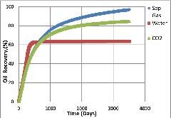
Figure 11: Downdip reservoir oil recovery with time Figure 14: Gas saturation in 1550 days for KV/Kh ratio 0.1
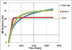
Figure 15: Gas saturation in 2950 days for KV/Kh ratio 0.0003
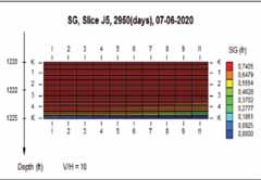
Figure 16: Gas saturation in 2950 days for KV/KH ratio 0.1 Figure 18: Oil saturation on 1550 days KV/KH ratio 0.1
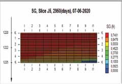
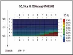
Figure 19: Oil saturation on 2950 days for KV/KH ratio 0.0003
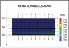
Figure 17: Oil saturation on 1550 days for KV/KH ratio 0.0003 Figure 20: Oil saturation on 2950 days KV/KH ratio 0.1