15 minute read
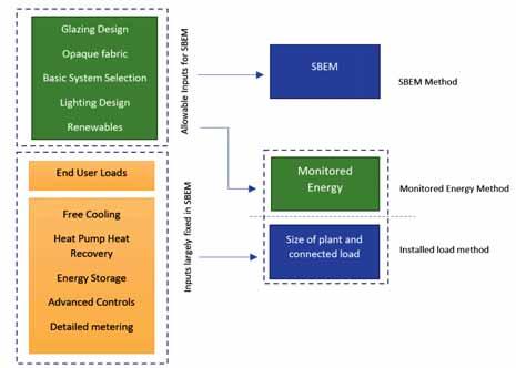
Simplified Building Energy Model


Prior to the introduction of SBEM (Simplified Building Energy Model), Part L of the Building Regulations relied largely on the setting of minimum fabric insulation requirements to reduce heat losses from buildings during the heating season. As consecutive revisions of Part L were introduced, insulation levels increased, and later air permeability targets were introduced. As fabric elemental performance increased, other aspects of design such as solar gains and system efficiencies became dominant in defining building energy performance, writes Chris Croly, Building Services Engineering Director, BDP (inset).
SBEM was introduced to capture some of the more complex interactions between heat gains and losses from the building fabric. SBEM also allowed the energy implications of basic system selection and design to be considered. The method attempted to introduce some flexibility in design by comparing the performance of a proposed building with that of a reference building with fixed fabric properties applied.
Advertisement
While it was a useful tool for expanding the scope of Part L, it is also of limited benefit in accurately assessing the environmental performance of the next generation of buildings. A further refinement of SBEM targets is likely to be ineffective as the method is not designed to assess the modern techniques that are required to further improve building performance.
The method has a number of wellestablished limitations and these are as follows:
The method actively excludes the largest source of carbon emissions from buildings. The selection and usage of equipment such as computing and audio-visual equipment in buildings often contributes to over 80% of their total energy usage. The philosophy traditionally applied is that the energy performance of buildings should be judged in isolation from the end-user equipment that they contain. Buildings can, however, no longer be divorced from their content when their content has become the driving indicator of their overall carbon impact.
In buildings that contain active cooling, the end-user equipment strategies applied also have a direct effect on cooling demand. This is not addressed by SBEM and the actual cooling load of two buildings may vary by more than a factor of two, while SBEM reports identical estimates of cooling energy. SBEM is agnostic to the size of the cooling plant actually installed.
If the carbon impact of buildings is to be reduced notably beyond current practice, it is essential to address loads that are housed within buildings.
SBEM is not currently capable of considering many of the modern techniques required to further reduce energy usage in buildings.
Techniques such as heat pump driven heat recovery, free cooling, energy storage, mixed system strategies and parasitic load reduction are not addressed by SBEM. While SBEM could be patched to address some of these issues, many are too complex to easily include within the SBEM calculation. Embodied energy constraints limit further development of SBEM.
In well-designed buildings, the energy lost through the building fabric has reached a practical limit. In buildings with a heating bias, the addition of further insulation would typically increase the embodied energy of the structure at a higher rate than the energy saved. In buildings that combine heating and cooling loads, SBEM already achieves a reasonable balance and leaves little scope for further fabric refinement. The method is unnecessarily time-consuming to implement relative to Its benefits.
Much of what is achieved through the use of SBEM could be achieved for modern buildings by following a number of simple rules. Many of the complexities of the SBEM calculation result in modest variations in the results achieved.
The method offers limited support for design flexibility and innovation.
The method does not support many flexible and innovative solutions to lowering the carbon impact of buildings as it is built around a set of assumed solutions to the main sources of carbon emissions associated with buildings. Some of these assumed solutions have already been superseded by advances in technology. Building design is advancing at a faster rate than the rate of update of the calculation method.
The method doesn’t consider occupant density.
The energy usage within two hotels, for example, could vary by over 100% while receiving identical assessments from SBEM. This is because there is no consideration of the area used per person served. SBEM actually rewards the inefficient use of a building area by increasing the area of the reference building in proportion to the design proposal.
The method contains a number of known loopholes.
One method of easily improving an SBEM result is to use a water-to-water chiller with a dry cooler as SBEM requires only the efficiency of the chiller to be entered. This means that the fan and pumping energy used by the dry cooler is excluded from the calculation. The equivalent fan and pump (compressor) energy would be included if using a chiller with integrated heat rejector. Known loopholes such as this are actively exploited.
Updating SBEM
The useful life-cycle of SBEM could be extended by updating the calculation to address some of the elements excluded. The update would be complex, and the calculation would not be inherently futureproofed. The largest carbon impact in buildings (end-user energy) would also remain unaddressed.
Ultimately, the SBEM calculation method is designed for a different generation when basic fabric performance issues were a key driver of building performance. The performance of modern, well-insulated, airtight buildings with optimised glazing areas is no longer defined by deviations in fabric performance and a tool that is tuned to differentiate fabric performance is of limited future application.
The tool may continue to be of benefit in the assessment of the performance of older buildings.
Level 5 Simulation
It has long been proposed that replacing the SBEM calculation with full dynamic simulation would allow the inclusion of advanced solutions to be more accurately assessed.
The process involves creating a dynamic simulation of a refence building and the actual design in a similar manner to the technique used with SBEM. The designers are then given the flexibility to adjust and tune the design of the actual building design.
Unfortunately, the flexibility of the method proved to also be its weakness. Dynamic simulation is very susceptible to the manipulation of outputs through the adjustments of inputs.
One solution is to fully define consistent inputs for both the reference and actual model but that ultimately defeats the purpose of the method, limiting its usefulness to simply offering a more detailed assessment of fabric thermal performance.
The very flexibility offered by the software unfortunately limits its usefulness as a tool for standardisation. The method also fails to address end-user energy or the difference between theoretical and actual building performance.
Monitored energy usage limitations
Ideally, Part L would ultimately be replaced by a system that judges a building’s energy performance based on its actual monitored energy consumption, in addition to the theoretical performance of the fabric and systems design.
Once minimum construction standards are achieved, the poor performance of buildings could be addressed through an extension to the principles of smart metering. The energy tariff applied could increase as the relative usage increased, rather than the current norm where larger energy usage is bizarrely often rewarded with a lower tariff.
While addressing actual energy consumption is logical, it may not be politically acceptable and is potentially open to misuse as a taxation tool.
Installed load moderation
This is a new concept which proposes that a building’s energy performance is judged based on two key metrics as follows:
• The installed plant load for the building;
• The total installed power connection to the building.
There is a very strong correlation between the minimum size required for the above metrics and the actual energy consumption of a building. It is hypostasised that the correlation is much stronger than that between an SBEM result and a building’s actual energy performance as the method targets the actual outputs of interest instead of an interim indicator.
The outputs selected are a function of the following:
• The fabric performance of the building;
• The type and efficiency of the installed systems;
• The end-user equipment installed;
• The control and operation of both equipment and end-user loads.
The method would be implemented by setting a maximum installed systems load (heating, cooling, hot water, fans and pumps) value for each building type, and assessing a building’s performance on its installed load. An additional performance metric would be applied for the overall building connected (non-renewable) load.
These targets set would be combined with a number of simple existing constraints on key fabric element thermal performance, solar gains and systems as detailed currently within the existing Part L. This approach offers a considerably simpler and more direct solution than SBEM to assessing the total operational carbon impact of buildings.
While the simplicity of the approach may lead to the assumption that it cannot address the complex issues described above, most of the limitations of SBEM benefit from this simplicity as follows:
Flexibility and innovation
There is no constraint on the calculation tools, or the innovations used to reduce building loads, because the result rather than the inputs are assessed. Designers are free to use any design technique or tool they deem most appropriate for the building.
Occupant density
The installed load target can be specified in two forms. The target would, in some cases such as offices, be expressed in terms of building area where it is the key metric of interest. Where occupancy served is the primary metric of value, such as hotels, the figures could be expressed in terms of the number of beds provided. This method penalises the production of buildings that are inefficient in the use of space.
Time
The method is much quicker and easier to implement than SBEM as it does not require bespoke software to be developed and maintained. Nor does it require an additional design task so this frees up designers to concentrate on building design.
End-user loads
End-user energy use would no longer be divorced from the building’s carbon impact as all energy consumed therein is considered.
Input bias
The methodology is less susceptible to input bias and is therefore less open to manipulation of the result achieved. The inputs become irrelevant as only the output is assessed.
Performance gap
The solution would be to address the perceived “performance gap” as buildings that fail to achieve the design load would simply not be fully operational at handover until their design flaws were rectified.
Renewable energy limitations
The trading of renewable energy with energy efficiency occurs naturally within the method. Designers could use renewable energy to reduce installed loads. The method only considers carbon emissions and not the source of their reduction, which is left entirely to the designers.
Limitations of load moderation method
As with any method that is applied to a large number of buildings, there would be complexities and exceptions to be addressed. However, the method appears fundamentally less susceptible to complexity as many of the details can be referred to building designers where they are best addressed.
As with SBEM, it would be necessary to address the concept of process loads. The view could be taken that most process loads can be addressed simply by requiring the design team to use further energy saving methods and renewables to address any issues.
It would be necessary, however, to exclude some process loads for some building types. The principle behind the definition of process loads should be clearly defined.
The method automatically deals with buildings that have extended periods of operation as it is the connected load and not the energy usage that is directly constrained. It is reasonable to extend the energy used when providing an extended service.
The method proposed has a limited effect on the control of parasitic losses, but it does reward strategies that use energy storage to improve the time of use response of energy systems.
There is a risk that an end-user could upgrade systems after completion to bypass the method, but this is also a risk with the current SBEM method. The requirement to routinely update the certification would resolve this issue. As the method is much simpler than the SBEM method to implement, the provision of regular updates would not require the same overhead.
Renewable energy
The current version of Part L requires the provision of a set percentage of renewable energy from on-site sources. This proposal was often debated as the end-goal is to reduce the carbon impact of a building, and reducing energy demand is of similar (if not greater) value as an alternative strategy to using renewable energy. Part L tried to address this issue by adjusting the renewable contribution with a step change allowance based on the SBEM result achieved.
The installed load method would address the issue automatically as the designers have the option of using renewable energy generation (combined with storage or load modulation) to meet the capacity limits set for the electrical connection.
An on-site renewable requirement could, however, also be included. The difficulties with varying site constraints could be addressed simply be defining the required renewable contribution relative to the site footprint, instead of the current method of using the building area. Defining renewable energy as a percentage of usage as is currently used is problematic as it does not compensate for site opportunity.
Any future method should exclude the consideration of heat pumps as a form of renewable energy. The designation of a heat pump as a renewable energy system was a useful transitional arrangement but heat pumps are not renewable energy sources by definition. They are now a standard solution for almost all buildings rather than an option, and the setting of base electrical import limits should assume the application of heat pumps (or equivalent).
Any renewable energy requirement should exclude sources of significant local pollution or traffic congestion.
Energy labels
While SBEM continues to be a reasonable method of assigning energy labels for older buildings, it has proved impractical for new constructions and refurbishments. Almost all new buildings of the same type achieve the same energy label, irrespective of their actual performance. There is inadequate resolution within the system to differentiate between buildings.
With an upgraded energy performance requirement, and more importantly developments in lighting efficiency (which significantly influences the SBEM result), all buildings are likely to achieve an A2 rating by default when using SBEM.
As it would be confusing to recalibrate the labelling system, the logical option is to sub-divide the A category. The subdivision would have limited meaning if trying to differentiate by using SBEM but, if using the connected load method, subcategories could easily be used to regrade the labelling system by sub dividing the A category.
Conclusions
The energy performance of new buildings has reached the point where continuing to focus on improved fabric performance will result in rapidly-diminishing returns. It is necessary for the development of any future method used to accept that end-user loads are the largest driver of energy consumption in buildings, and that a building’s design can no longer be considered in isolation of its content.
An innovative change of approach is required to address this reality and the defining of building performance based on installed loads is one potential alterative method of achieving this.
The method offers many advantages and encourages designers and building users to work together to achieve new, flexible solutions to reducing the carbon impact of buildings.
Everything you need to keep glowing
Say hello to the Energy range
Glow-worm’s Energy boiler range offers attractive modern design, easy-to-use interfaces and a wide choice of models and controls. Its lightweight, compact construction makes life easy for installers, while its long-lasting, quiet performance is a hit with homeowners too.
Energy Combi
•ErP A-rated for efficiency
•Compact size allows installation flexibility, H700mm W390mm
D280mm
•High efficiency
•Low running costs
•Outputs – 25kW, 30kW or 35kW
•Rear flue option
•“Quiet Mark” approved
•Aluminium heat exchanger
•Modulating Grundfos pump
•Up to 10 metres flue length
Energy Regular
•ErP A-rated for efficiency
•Outputs – 12kW, 15kW, 18kW, 25kW or 30kW
•Compact size/cupboard fit, H600mm W375mm
D280mm
•Rear flue option
•Low energy bills
•Easy to maintain
•Up to 10 metres flue length
Energy System
•Outputs –12kW, 15kW, 18kW, 25kW or 30kW
•Compact size, H700mm W390mm
D280mm
•Rear flue option
•ErP A-rated for efficiency
•Quiet Mark approved
•Easy to fit and install
•Modulating Grundfos pump
•Low running costs
•Up to 10 metres flue length


Combi
• Stainless steel heat exchanger
• User-friendly display for quick commissioning
• Optional analogue clock
• Combi boiler available in 24kw & 28kw out puts, NG & LPG
• 25mm spacer frame to allow fitting in standard 300mm cupboard
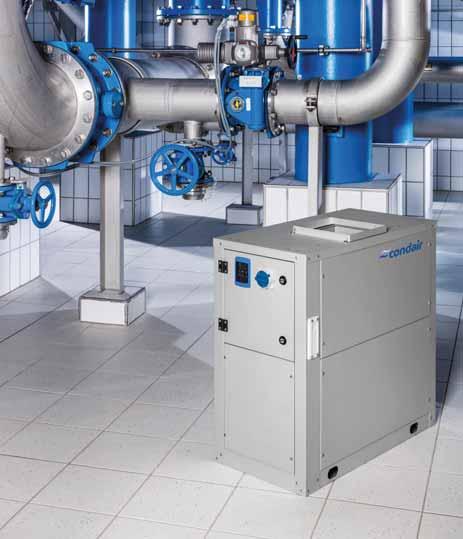
HUMIDITY
Lowering the humidity in a room can be a complicated task. The drying of air can have a dramatic impact on its temperature and, depending on the type of dehumidifier being used, there can be various installation obstacles to overcome. So, what should a contractor consider before setting out on a drying project?
In this article Damien Power, Area Sales Manager (Ireland), at Condair, pictured right, looks at what a HVAC contractor should know to successfully deliver a dehumidifier project.

Firstly, which technology to use?
There are two main types –condensing and desiccant. A condensing system collects moisture by condensing it on a cold surface and then sending it to drain. A desiccant literally adsorbs moisture by passing air through a desiccant rotor.

Due to the nature of condensing systems, they work better in warmer conditions, as more condensation occurs. This technology is ideal in rooms of 20°C or more and for projects that need to lower humidity down to around 45-50%RH. As the room’s temperature has no impact on the ability of the desiccant to adsorb moisture, it can be used in any temperature, making it a more flexible solution and ideal for cold environments. This technology can also lower humidity below 45%RH.


Installing a condensing system is potentially simpler as it only requires connections for power and drain. A desiccant dehumidifier doesn’t need a drain but does need a duct to vent hot wet air away from the area being dried. To remove moisture from the desiccant rotor, a secondary hot airstream is passed through the rotor, which carries the moisture away to outside.
Pressure management must be considered whenever a dehum has ducting. Each model has a pressure rating and inadequate or excessive airflow through the system may reduce efficiency or cause wetting issues. As there are two airflows through a desiccant system, care must also be taken to avoid crossflow through the rotor. Installing short ducts on both intakes will allow for dampers to be fitted, which can help manage internal pressure and avoid cross flow issues.
Alongside pressure, temperature management must also be reviewed by the contractor. The thermodynamic principle of drying produces heat at around 680W per kg of moisture extracted. In addition to this, the mechanical elements incorporated into both technologies produce heat. Without assessing and controlling this, the area being dried can experience significant heat gain.
All too frequently the heat gain from dehumidification is countered by venting an area. However, opening windows or proactively bringing in outside air can reintroduce moisture and impact humidity control. For condensing systems, if the heat gain is too great, some units, such as the Condair DC-N, have a secondary condenser that can be located outside. This is similar to a split air con unit and allows the heat in the refrigerant loop to be remotely exhausted and the dry air delivered to the room at a precise temperature and humidity.
Heat gain in desiccant systems will be greater than condensing, as the “regeneration” portion of the desiccant wheel is heated to remove the moisture. This heat transfers to the process airflow as the rotor revolves, and so adds significant heat to the dry airflow. To counter this, a contractor can install a cooling coil before or after the dehumidifier.
Dehumidifier location is another important decision to be made early in the project. If the unit is placed inside the area to be dehumidified, installation can be simpler with less ducting needed to direct airflows. Air can be taken from the area being dried and then delivered directly back to it. Using the room air rather than outside air for the intake airflow can be more consistent in its condition, and therefore lead to more accurate humidity control. Internal air often has less moisture than outside air, potentially resulting in a smaller dehumidifier being needed.


However, many other location and airflow configurations are available, including supply air being drawn from outside to over-pressurise an area and prevent air ingress. For areas that want a pressure-neutral arrangement with a desiccant system, the regeneration airstream can intake and exhaust externally, with the process air coming from and being delivered back to the room being treated. Understanding exactly what internal conditions are required by the client’s team will help a contractor liaise with the supplier to find the best location and airflow set-up. Many other questions also need to be asked by the contractor to determine the size of unit needed. To provide a dehumidifier with an adequate capacity, a supplier will need to know what the required room condition is, the size of the space (and therefore air volume), and how much air exchange takes place in the area. This might be through open doors or windows, or via an air handling unit. If the area is naturally ventilated, air exchange estimates need to be made and knowing how many doors, their size and how often they open is essential information. In addition to these factors, the number of people in the area and their activities is required, along with any open sources of water. Giving this information to the supplier will allow a psychrometric calculation to be performed and a suitably sized unit to be offered. A quality supplier will be both able and willing to give advice on sizing information, along with all the other issues mentioned above. However, it greatly helps to avoid common pitfalls and deliver a successful project if these topics are considered as early as possible in a dehumidifier project.


