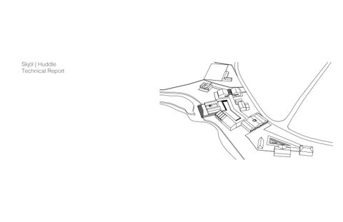
Skjรณl | Huddle Technical Report
1.0. Energy Manifesto:
The sustainability goals for this project have been achieved through the use of successful lighting, effective heating, good ventilation, and impactful enclosures.
Annual Energy Use Estimate Report Summary Paniz Moayeri
Project Designer
20375120
Student ID Number 711 m2 769 m2 1361 m2
Total Net Floor Area Total Gross Floor Area Site Area
Estimated Total Annual Energy Use Energy Use by End-Use Space Heating Space Cooling Ventilation Water Heating Plug and Process Lighting Renewable Energy Generation
Window-to-Wall Ratio 0.63 Floor Area to Enclosure Ratio 0.59 Window Spec: U-value = 3.78 SHGC = 0.5 Daylight Fraction 0.14
96101 ekWh 13261 6780 12130 9484 19036 35410 0
kWh kWh kWh kWh kWh kWh kWh
Space Hea.ng 14% Ligh.ng 37%
2
Estimated Global Warming Potential Nitrogen oxides (NOx) Sulphur dioxide (SO2) Carbon dioxide (CO2) Equivalent to CO2 emissions from
28 65 15406 30.3
1.1 - Natural day lighting - Buildings Placed in the most lit part of the site. 1.2 - Skylights placed in “spines” bring light into central volumes as well as the areas in their parameter. Space Cooling 7%
Ventilation 12%
2
EUI with Renewable Energy
1. Lighting:
Energy Use by End-Use Table
125 ekWh/m /year 125 ekWh/m /year
Energy Use Intensity (EUI)
The program was split off to 6 smaller buildings, allowing for the shutting off the certain parts of the program in the off seasons or when not needed. The main buildings were supplied with a triptych design model with three pitched volumes. In each case, the central volume acts as a spine, allowing for a number of passive and mechanically oriented strategies to take place in the building.
Plug and Process 20%
Water Hea.ng 10%
1.3 - Light bulbs were changed to the most efficient LED model and washrooms, storage spaces, and other similar intermittently used spaces were given occupancy sensors. 2. Heating: 2.1 - The thermal mass of the exposed concrete slabs captures the heat from the skylights in the “spine” spaces, radiating the heat to the surrounding spaces passively.
kg kg kg cars
2.2 - The heat exchange from the geothermal hot water source is highly efficient, allowing for an easy source of hot water for the radiant floor heating system.
Energy Use Intensity Comparisons
450
436 419
Average Ontario Recreation Building [1]
EUI (kWh/m2/yr)
400 350 300 250 200 150 100 50
3. Ventilation:
Average Ontario Service Building [1]
Current Practice - Good [2]
3.1 - The hot air rising from the concrete’s heated thermal mass, as well as the radiantly heated floors, rises up in the spinal spaces, exhausting from the roof skylights in their centres.
Current Practice - Better
275
Current Practice - Best
200
Paniz Moayeri's Project
174 125 125
131
Architecture 2030 Target - Today [3]
87
Architecture 2030 Target - 2015
44 0
0
3.2 - High-velocity air is supplied through the low vents in the side spaces, heating up and rising through the spinal spaces, exhausting from the skylights in the spines.
Architecture 2030 Target - 2020 Architecture 2030 Target - 2025 Architecture 2030 Target - 2030
4. Enclosures:
Notes: [1] EUI for Average Canadian Office Building is from Natural Resources Canada "Commercial and Institutional Building Energy Use Survey 2000"
4.1 Highly insulated enclosures have been designed for the buildings, reducing the demands for heat.
[2] EUI for Good, Better and Best Current Practice is based on current experience for this building type [3] More information about the Architecture 2030 Challenge can be found at http://architecture2030.org/
2 15-07-03 7:48 AM
Daylight Fraction
Total Net Floor Area Total Gross Floor Area Site Area
2 Energy Intensity ekWh/m /year (EUI) 116Use
Energy Use Intensity (EUI)
6990 83 2942 2826 3670 12471 0
2
kWh kWh kWh kWh kWh kWh kWh
Estimated Total Annual Energy Use Energy Use Energy by End-Use Table Use by End-Use Space Heating Space Cooling Ventilation Water Heating Space Plug and Process Hea.ng Lighting 24% Space Cooling Renewable Energy Generation
2
28319 ekWh
106 ekWh/m /year 106 ekWh/m /year
Process 41%
69 2513 3631 1047 11631 9429 0
kWh kWh kWh kWh kWh kWh kWh
Plug and
Water Estimated Total Annual Energy Use Process Use by End-Use Energy Use Energy by End-Use Table Hea.ng 3% Heating Space 12% Space Space Cooling Hea.ng 0% Ventilation Space Ventilation Water Heating Cooling 13% Plug and Process 9% Lighting Water Ligh.ng Hea.ng 33% Renewable Energy Generation
125 116
Notes:
275
0
350
20 kg 4646 kg 9.1 cars
Building [1]
436 Average Ontario Service Building [1]
400
2
Ventilation 10%
Water Hea.ng Plug and 10% Process Estimated 13% Global Warming
2
Plug and Process 41%
Estimated Global Warming Potential Nitrogen oxides (NOx) Sulphur dioxide (SO2) Carbon dioxide (CO2) Equivalent to CO2 emissions from
Potential
Energy Use Intensity Comparisons 9 kg Nitrogen oxides (NOx) 8 kg Comparisons Energy Use Intensity
Average Ontario Recreation450 Building [1] Current Practice - Good [2] 400 419
450
Current Practice - Good [2]
400
250
0
0
450
436 419
2
Water Hea.ng 22%
Average Service Energy Use Intensity Ontario Comparisons
419
Average Ontario Recreation Building [1]
300
200 131 150 87 100 44 50
Building [1]436
450
2
4%
Average Ontario Recreation Building [1]
400
Current Practice - Good [2]
350
Sulphur dioxide (SO2) Carbon dioxide (CO2) Equivalent to CO2 emissions from
436 419
19 kg 4540 kg 8.9 cars
Average Ontario Service Building436 [1]
Energy Use Intensity Comparisons
419
450 Average Ontario Recreation Building [1]
Average Ontario Service Building 436 [1]
419
Current Practice - 400 Good [2]
450 Recreation Building [1] Average Ontario 400 - Good [2] Current Practice
Average Ontario Energy Use Intensity Comparisons
1661 kWh 3742 kWh 2503 kWh 1635 kWh 445 kWh Ventilation 3829 kWh 18% 0 kWh
kg kg kg140 cars 140
4 9 2215 4.4
Ligh.ng Window-to-Wall Total Net Floor AreaRatio 43% FloorTotal AreaGross to Enclosure Ratio Floor Area
144 m2 162 m2 400 m2
0.20 0.32 Window Site AreaSpec: U-value = 0.9 SHGC = 0.5 Daylight Fraction 0.88
Estimated Total Annual Energy Use Energy Use by End-Use Energy Use byTable End-Use Space Heating Plug and Space Cooling Process Ventilation 13% Water Heating Space Hea.ng Plug and Process 12% Ligh.ng Lighting 28% Renewable Energy Generation
Water Hea.ng 10%
Space
ekWh/m2/year
Plug and Process 3%
Service Building [1]
17338 ekWh 3117 147 2561 2272 2106 7136 0
Energy Use by End-Us
kWh kWh kWh kWh kWh kWh kWh
2
12%
5 12 2779 5.5
Building [1]
Average Ontario Recreation Building [1]
419
Current Practice - Good [2]
Current Practice - Good [2]
Current 400
Average Ontario S
419
Average 450 Ontario Recreation Building [1]
Current Practice - Good [2]
Plug and Process 12%
kg kg kg cars
Average Ontario Service436 Building [1]
Average Ontario Recreation Building [1]
Ligh.ng 41%
2
Water EUI with Renewable Energy Hea.ng
Average Service Energy Use IntensityOntario Comparisons
Window-to-W Floor Area to Enclos Window Spec: U Dayligh
107 ekWh/m /year 107 ekWh/m /year
Estimated Global Warming Potential Ventilation Nitrogen oxides (NOx) 18% Sulphur dioxide (SO2) Carbon dioxide (CO2) Equivalent to CO2 emissions from
kg kg kg cars
Space Cooling 0%
Ventilation 10%
Cooling Energy Use Intensity 27% (EUI)
ekWh/m2/year
Average Ontario Recreation Building [1]
400
24%
20375120
Student ID Number
Average Ontario Service Building 436 [1]
450
Hea.ng Paniz Moayeri
Average Ontario R
Practice - Good [2]
Current Practice - G
350 350 350 -Current Practice - 350 Better Current Practice Better Current Practice - Better Current Practice - B Current Practice - Better Current 275 Practice - Better 275 - Better 275 Current Practice 275 275 Current Practice 300 - Best 300 300 - Best Current Practice Current Practice - Best Current Practice - B Current Practice - Best 300 300 200 250 200 200 250 250 Project 250 200 250 Project Current Practice - 300 Best 174 Current Paniz Moayeri's Paniz Moayeri's Paniz Moayeri's Pr Paniz Moayeri's Project Practice - Best Paniz Moayeri's Project Current Practice - Best Current Practice -200 Best 174 Current Practice Best 174 174 174 166 200 200 200 200 Architecture 2030 Target - Today [3] 131 Architecture 2030 Target - Today [3] Architecture 2030 T Architecture 2030 Target - Today [3] 200 Architecture 2030 Target - Today [3] 250 131 131 131 200 200 131 125 125 140 125 125 125 200 116 200 250 106 250 107 Paniz Moayeri's Project 150 Paniz Moayeri's Project 150 150 150 150 Moayeri's Project 87 Paniz Moayeri's 87 87 87 87 Architecture 2030 Target - 2015 Moayeri's Project 174 Project ArchitecturePaniz 2030 Target - 2015 Architecture 2030 T Architecture 2030 Target - 2015 174 Architecture 2030 TargetPaniz - 2015 174 166 174 100 100 100 100 100 44 44 44 44 200 Architecture 2030 Target - 2020 Architecture 2030 Target - 2020 Architecture 2030 T Architecture 2030 Target - 2020 Architecture 2030 Target - 2020 200 [3] 44 0 140 Architecture 2030 200 Target - Today [3] Architecture 2030 Target - Today 131 131 50 0 0 Architecture 2030 Target Today [3] 0 50 50 50 0 50 131 125 Architecture 2030 Target - Today [3] 125 Architecture 2030 Target Today [3] 131 125 Architecture 2030 Target - 2025 Architecture 2030 Target - 2025 Architecture 2030 T Architecture 2030 Target - 2025 Architecture 2030 Target - 2025 125 0 0 106 0 0 107 0 150 150 Architecture 2030 Target - 2030 Architecture 2030 Target - 2030 Architecture 2030 T Architecture 2030 Target - 2030 Architecture 2030 Target - 2030 87 - 2015 Architecture 2030 150 Target - 2015 87 Architecture 2030 Target - 87 2015 Architecture 203087 Target - 2015 Architecture 2030 Target Architecture 2030 Target - 2015 100 44 100 44 44 Architecture 2030 100 Target - 2020 44 Notes: Architecture 2030 Target - 2020 Notes: Notes: Notes: Notes: Architecture 2030 Target - 2020 Architecture 2030 Target - 2020 Architecture 2030 Target - 2020 [1] EUI for Average Office Building is from Natural Resources Canada "Commercial and Institutional Building Energy Use Survey 2000"Office Building is from Natural Resources Canada "Commercial and Institutional Building [1] EUI for Average Canadian Energy UseCanadian Survey 2000" [1] EUI for Average Office Building is from Natural Resources Canada "Commercial and Institutional Building Energy Use [1] EUI for Average Canadian Office Building is from Natural Energy UseCanadian Survey 2000" [1] EUI for Average Canadian Energy Use Survey 2000"Office Building is from Natural Resources Canada "Commercial and Institutional Building 0 50 Resources Canada0 "Commercial and Institutional Building 0 50 0 50 [2] EUI for Good, Better and Best Current Practice is based- on current experience for this building type [2] EUI for Good, Better and Best Current Practice is based on current experience [2] EUI for Good, Better and Best Current Practice is based on current experience for this building type [2] EUI for Good, Better and Best Current Practice is based on current experience for this building type [2] EUI for Good, Better and Best Current Practice is based on experience for this building type Architecture 2030 Target - current 2025 Architecture 2030 Target 2025 Architecture 2030 Target - 2025 for this building type Architecture 2030 Target - 2025 Architecture 2030 Target - 2025 [3] More information about the Architecture 2030 Challenge can be found at http://architecture2030.org/ [3] More information about the Architecture 2030 Challenge can be found at http://architecture2030.org/ [3] More information about the Architecture 2030 Challenge can be found at http://architecture2030.org/ [3] More information about the Architecture 2030 Challenge can be found at http://architecture2030.org/ [3] More information about the Architecture 2030 Challenge can be found at http://architecture2030.org/ 0 0 0 - 2030 Architecture 2030 Target Architecture 2030 Target - 2030 350
Current Practice 275 - Better
300
275
350 Current
Current Practice - Better
300
Practice 275 - Better
EUI (kWh/m2/yr)
174
Average Service Energy Use Intensity Ontario Comparisons
0%
Space
2 27%
13815 ekWh 2
0.33
Annual Energy Use Estimate Report Summary Project Designer
EUI (kWh/m2/yr)
200
5 kg 1226 kg 2.4 cars
Ligh.ng 43%
EUI (kWh/m2/yr)
275
436 419
EUI (kWh/m2/yr)
450
EUI (kWh/m2/yr)
436 419
50
Notes:
Hea.ng 13%
Estimated Global Warming Potential Nitrogen oxides (NOx) Sulphur dioxide (SO2) Carbon dioxide (CO2) Equivalent to CO2 emissions from
Energy Use Intensity Comparisons 2 kg
Energy Use Intensity Comparisons
EUI (kWh/m2/yr)
EUI (kWh/m2/yr)
100
Plug and Process 16%
Estimated Global Warming Potential Nitrogen oxides (NOx) Sulphur dioxide (SO2) Carbon dioxide (CO2) Equivalent to CO2 emissions from
350
150
28984 ekWh
Ventilation 6%
2
350
200
kWh kWh kWh kWh kWh kWh kWh
2
400
250
1424 295 493 1704 1184 2545 0
Energy140 Use Intensity (EUI) ekWh/m2/year
Daylight Fraction
Energy Use by End-Use Table
98 m2 98 m2 Space 276 m2Cooling
Total Net Floor Area Window-to-Wall Ratio 0.06 Totalto Gross Floor Area Floor Area Enclosure Ratio 0.55 Site Area Window Spec: U-value = 0.9 SHGC = 0.5 Daylight Fraction 0.08
Estimated Global Warming Potential Estimated Global Warming Potential Estimated Global Warming Potential Estimated Global Warming Potential Nitrogen 8 kg oxides (NOx) Nitrogen2 oxides (NOx) 5 kgoxides (NOx) Nitrogen 4 kg(NOx) kg Nitrogen oxides 9 Sulphur dioxide (SO2) 19 kg dioxide (SO2) Sulphur5dioxide (SO2) 12 kg Sulphur 9 kg(SO2) kg Sulphur dioxide 20 Carbon dioxide (CO2/year ) kg dioxide Carbon (CO2) 2779 kg Carbon 2215 Energy Use Intensity (EUI) 4540 1226dioxide kg Energy Use Intensity (EUI) Energy Use Intensity (EUI) Energy Use Intensity (EUI) ekWh/m (CO /year 2) Carbon dioxide 4646 106 ekWh/m 116 ekWh/m 166kg(CO 2) /year Equivalent to CO from 8.9 106 cars ekWh/m Equivalent to CO2 emissions from to CO from cars 2 emissionsEUI 2.4 cars Equivalent4.4 to CO from 2 emissions with Renewable Energy Equivalent EUI with Renewable Energy9.1 EUI with Renewable Energy5.5 cars EUI with Renewable Energy /year /year ekWh/m /year 2 emissions 116 ekWh/m 166
400 300
Hea.ng 22%
130 m2 170 m2 467 m2
EUI with Renewable Energy EUI with ekWh/m /year 166 Renewable Energy ekWh/m /year 140 Water Plug and
Estimated Total Annual Energy Use Energy Use by Table End-Use Energy Use by End-Use Space Heating Plug and Space Cooling Process Ventilation 12% Water Heating Space Plug and Process Hea.ng 19% Lighting Space Ligh.ng Cooling 33% Renewable Energy Generation 4%
7645 ekWh
Window-to-Wall Ratio 0.33 Total Net Floor Area Floor Area Enclosure 0.57 TotaltoGross Floor Ratio Area Window Spec: U-value = 0.9 SHGC = 0.5 Site Area Daylight Fraction 0.33
Energy Use Intensity (EUI) /year 166 ekWh/m
Energy Intensity ekWh/m /year (EUI) 107 Use
Estimated Total Annual Energy Use Energy Use by End-Use Plug and Space Heating Process Space Cooling 16% Ventilation Water Heating Plug and Process Lighting Renewable Energy Generation
273 m Ventilation 273 m2 525 m2 15% 2
EUI (kWh/m2/yr)
Estimated Global Warming Potential Nitrogen oxides (NOx) Sulphur dioxide (SO2) Carbon dioxide (CO2) Equivalent to CO2 emissions from
41% Area Ratio TotalWindow-to-Wall Net Floor 0.15 Total Gross Floor Area Floor Area to Enclosure Ratio 0.40 Site AreaSpec: U-value = 0.9 SHGC = 0.5 Window Daylight Fraction 0.18
2 EUI with Renewable ekWh/m /year Energy 107 Water
EUI 116 with Renewable ekWh/m2/yearEnergy
EUI with Renewable Energy
66 m2 Ventilation 66 m2 6% 160 m2 2
2
EUI (kWh/m2/yr)
Summery of Energy Use on Site
EUI (kWh/m2/yr)
2.0. Energy Manifesto Illustrated: General Over-View
450
0.88
Estimated 28319 ekWh Estimated Total Annual Energy Use 17338 Total ekWhAnnual Energy Use Estimated Total Annual Energy Use 13815Annual ekWh Energy Use 7645 ekWh Estimated Total 28984 ekWh Energy Use by End-Use Energy Use by End-UseEnergy Energy Use by End-Use Table Use by End-UseEnergy Use by End-Use Energy Use by End-Use Table Energy Use by End-Use Table Energy Table Use by End-Use Space 69 kWh Space Heating 3117 Heating kWh Space Heating 1661 kWh 1424 kWh Space Heating 6990 kWh Space Space 2513 Space Cooling 147 Cooling kWh SpacekWh Cooling 3742 kWh Hea.ng 295 kWh Space Cooling 83 kWh 0% Ventilation 3631 kWh Ventilation 2561 kWh Ventilation 2503 kWh 493 kWh Ventilation 2942 kWh Space 1635 kWhVentilation Water 1047 kWh Water Heating 2272 Heating kWh Water Heating 1704 kWh Space Water Heating 2826 kWh Space Cooling 13% Space Annual Energy Use Estimate Report Summary Annual Energy Use Estimate Report Annual Energy Use Estimate Report Summary Annual Energy Use Estimate Report Summary Hea.ng Summary Plug and Process 11631 kWh Plug1184 and Process 2106 kWh Hea.ng and Plug Process 445 kWh 9% Process kWh Plug and 3670 kWh Space Hea.ng 12% 18% 19% Project Designer Paniz Moayeri Project Designer Ligh.ng Project Designer Project Designer Moayeri Moayeri Lighting 9429 kWh Cooling Paniz Moayeri Lighting 7136Paniz kWh Lighting 3829 kWh Water 2545 kWh Space Lighting 12471Paniz kWh Ligh.ng Ligh.ng 28% 1% Hea.ng Cooling 33% Student ID Number 20375120 Renewable Energy Generation 0 kWh Student ID Number Student ID Number Student ID Number 20375120 20375120 Renewable Energy Generation 0 kWh 33% Renewable Energy Generation 0 kWhGeneration 0 kWh Renewable Energy 0 kWh 4% Ligh.ng 4%
Estimated Total Annual Energy Use Energy Use by End-Use Space Heating Space Cooling Ventilation Water Heating Plug and Process Lighting Renewable Energy Generation
Energy Use Intensity Comparisons
Daylight Fraction
0.18
Architecture 2030 Target - 2030
Architecture 2030 Target - 2030
Notes:
Notes:
Architecture 2030 Target - 2030
Notes:
[1] EUI Average Canadian Office Building is Building from Natural Resources "Commercial and Institutional Energy Use SurveyCanada 2000" EUI for Average Office is from NaturalEnergy Resources Canada "Commercial and Institutional Energy Use [1]Survey EUICanada for2000" Average Canadian Office Building Building is from Natural "Commercial and Institutional Building Energy Canada Use Survey 2000" [1] EUI for Average Canadian Office Building is from Natural [1] Resources Canada Canadian "Commercial andBuilding Institutional Building Use for Survey 2000" [1] EUIResources for Average Canadian Office Building is from Natural Resources "Commercial and Institutional Building Energy Use Survey 2000" 15-06-27 10:14 PM 15-06-27 10:14 PM 15-06-27 10:15 PM 15-07-03 7:48 AM [2] EUI experience for Good, Better and Best Current experience this building [2] current EUI for experience Good, Better Current for this building type Practice is based on current [2] EUI for Good,for Better and Besttype Current Practice is based onfor current thisCurrent buildingPractice type is based on current experience for this building type [2] EUI for Good, Better and Best Current Practice is based on forand thisBest building typePractice is based on current [2] EUI Good,experience Better andfor Best about the Architecture 2030 Challenge can be[3]found http://architecture2030.org/ [3] More information about the Architecture 2030 Challenge can[3] beMore foundinformation at http://architecture2030.org/ Moreatinformation about the Architecture 2030 Challenge can information be found atabout http://architecture2030.org/ [3] More information about the Architecture 2030 Challenge can be found at http://architecture2030.org/ [3] More the Architecture 2030 Challenge can be found at http://architecture2030.org/
15-06-27 10:15 PM
15-06-27 10:15 PM
15-07-03 7:48 AM
15-06-27 10:14 PM
15-06-27 10:14 PM
Great Hall Building Greenhouse, Storage and Waste Disposal Spa Guest Accommodations
Full-Time, Care-takers’ Residence Extraction Well, Main Mechanical Space, Storage, and Outhouses
3
2.0. Energy Manifesto Illustrated: General Over-View Climate Zones
The hot geothermal pool has been enclosed with the surrounding buildings, resulting In a warmer micro climate formed in that area. The fire pit allows for the creation of a unique out-door microclimate.
80°C -100°C (Intermittent Use Only)
24°C - 32°C
Proposed Buildings
4
23°C - 25°C
Existing Buildings
19°C - 21°C
Outdoor Micro Climates Formed
17°C - 21°C (Transitory or Intermittent Use)
2.0. Energy Manifesto Illustrated: General Over-View The Use of The Spine in the Overall Strategies
The three main buildings on the site (the Great Hall Building, the Spa, and the Guest Accommodation Building) as well the full-time, care-takers’ residences all share a triptych design model with three pitched volumes. In each case, the central volume acts as a spine, allowing for a number of passive strategies to take place in the building.
The Great Hall Building
Full-Time, Care-takers’ Residence
Programmatically, the central spaces serve as communal, gathering, or passage spaces in the buildings with emphasized programmatic importance highlighted by their passive contributions. In case of the Spa, the Great Hall Building, and the Residence, there are skylights in the slightly higher middle volumes which allow for passive day-lighting, heating, and ventilation as discussed in more detail further in the report. In case of the Guest Accommodation Building, the spine is actually an outdoor circulation space, still providing the same services in the building.
Guest Accommodations
Spa
The “spines” have been highlighted here.
5
2.1. Energy Manifesto Illustrated: Passive Day Lighting Strategies Choice of Location on Site In addition to connecting to the existing buildings already at Dreki, the location chosen on the site allows for the most hours of day lighting available on the site as evidences by the following study.
6
7
2.1. Energy Manifesto Illustrated: Passive Day Lighting Strategies Positioning of Main Programs on the Site with Respect to Day Light Access
The programs have been arranged on the site with care given to their need for day lighting. The studies to the right look at the number of day lighting hours for each building per day, all summarized in the diagram directly below.
Mech. Storage Full
Time
t Gues s Room
Res
Spa G
re
Most Light
Least Light
8
en
G
ho
re
us
e
at
Ha
ll
9
2.1. Energy Manifesto Illustrated: Passive Day Lighting Strategies The Use of the Spine: Focus on Important Communal Spaces The sun lights the great hall and the communal spa treatment room (as well as their surrounding spaces) using the skylight in the buildings’ spines.
Summer Solstice (June 21st)
Spring/Fall Equinox (March 20 / September 22)
Winter Solstice (December 22) - Only small amounts of diffuse light enters the spaces. 10
2.2. Energy Manifesto Illustrated: Passive Heating Strategies The Site Conditions: Temperature and the Sun The following diagrams indicate the importance of heating at the site (and no need for cooling), and highlight the position of the sun during the hours when the solar heat gain would be needed.
Hourly annual temperature at the site.
Temperatures at which heating is required are indicated in blue.
The correlation between the position of the sun and the temperature
The blue indicates low temperatures during which heating is needed, diagrammed with respect to sun’s position at the same time. 11
2.2. Energy Manifesto Illustrated: Passive Heating Strategies The Exposure of the Programs to Direct Sun Rays for Heating
The programs have been arranged on the site with care given to their need for solar heat-gain. The studies to the right look at each building’s access to direct sunlight through out the year, and as such, heat gain. The gatherings have been summarized in the diagram below.
Mech. Storage Full
Time
t Gues s Room
Res
Spa G
re
Most Heat Gain
Least Heat Gain
12
en
G
ho
re
us
e
at
Ha
ll
13
2.2. Energy Manifesto Illustrated: Passive Heating Strategies The Use of the Spine: Focus on Important Communal Spaces The sun heats thermal mass of the concrete in the the great hall and the communal spa treatment room (as well as their surrounding spaces) using the skylight in the buildings’ spines.
Summer Solstice (June 21st)
Spring/Fall Equinox (March 20 / September 22)
Winter Solstice (December 22) - No real Heat gain since no direct sun light makes it inside the buildings. 14
2.3. Energy Manifesto Illustrated: Passive Ventilation Strategies The Site Conditions : The Wind
Hourly annual Wind speed at the site.
Only fast winds have been highlighted here. They mainly occur in winter.
Figure 15. Average surface wind vectors in winter (DJF) and summer (JJA) based on local observational time-series and linearly interpolated operational analyses, taking into account low surface wind speeds (2 speed < 5 m s−1 ). Average surface wind vectors in winter (DJF) and summer (JJA) based on local observational time-series and linearly interpolated 26 operational analyses, taking into account low surface wind speeds (2 ≤ speed < 5 m s−1) from the “Surface Wind and Air Temperature over Iceland based on Station Records and ECMWF Operational Analyses” study by the Icelandic Meteorological Office.
Figure 15. Average surface wind vectors in winter (DJF) and summer (JJA) based on Figure Average surface windand vectors in winter (DJF)operational and summer (JJA) based local 15. observational time-series linearly interpolated analyses, takingon into −1 local observational time-series and (2 linearly interpolated analyses, taking into account low surface wind speeds speed < 5 m s operational ).
The general area of the site has been highlighted in red.
15
2.3. Energy Manifesto Illustrated: Passive Ventilation Strategies The Positioning of the Buildings to Work with the Wind
The full impact of the fast winter winds from South and Southwest are slowed by the formation of the building ring around the pool, protecting it from extreme wind.
Proposed Buildings Existing Buildings Winter Winds Summer Winds
16
The slow summer breezes make their way through the gaps in the buildings, dispersing the hot air from the thermal pool.
2.3. Energy Manifesto Illustrated: Passive Ventilation Strategies The Use of the Spine: Focus on Important Communal Spaces
The hot air rising from the concrete’s heated thermal mass, as well as the radiantly heated floors, rises up in the spinal spaces, exhausting from the roof skylights.
High-velocity air is supplied through the low vents in the side spaces, heating up and rising through the spinal spaces, exhausting from the skylights.
17
3.1. Building Envelopes: Spa/Pool Wall Section
50.8mm (2”) Concrete Roof Panel Pool
River
180mm (7”) P.I.R Board Insulation 120mm Concrete Roof Out-door Shower-head Roll Curtain Triple Glazed, Argon Filled Low E-Coated Window 125mm Concrete Wall 12.7mm Rebar Reinforcement Beyond Control Layer (Water/Vapour Barrier) 101.6mm (4”) P.I.R Board Insulation 70mm Concrete Wall Panel
100mm Concrete Slab with In-floor Radiant Floor Heating Base-board Air-supply Vent Earth Flashing 101.6mm (4”) P.I.R Board Insulation Water Drain
Line Of Bed-rock
18
3.2. Building Envelopes: Typical Side Wall Section
120mm Concrete Roof 180mm (7”) P.I.R Board Insulation 50.8mm (2”) Concrete Roof Panel
125mm Concrete Shear Wall 12.7mm Rebar Reinforcement Beyond Control Layer (Water/Vapour Barrier) 101.6mm (4”) P.I.R Board Insulation Precast Connection 70mm Concrete Wall Panel 100mm Concrete Slab with In-floor Radiant Floor Heating In-floor Air-supply Vent Earth Flashing 101.6mm (4”) P.I.R Board Insulation
Line Of Bed-rock 19
3.3. Building Envelopes: Typical Edge Gutter Detail
- Stainless Steel Welded Wire Reinforcing Mesh - Line of Panel Bottom Beyond, Shown Dashed - 50.8mm (2”) Concrete Roof Panel
- 70mm (35mm in the Narrow, Gutter Section) Concrete Wall Panel - Control Layer (Water/Vapour Barrier) - Stainless Steel Trough - 101.6mm (4”) (2” in the Narrow Section) P.I.R Board Insulation - Precast Connection - 12.7mm Rebar Reinforcement Beyond - 120mm Concrete Roof 20
- 25mm Acrylonitrile Butadiene Styrene (ABS) or Rubber Pedestal @ 600 O.C. - Roofing Material - 7.5mm Plywood - 180mm (7”) P.I.R Board Insulation - 12.7mm Rebar Reinforcement Beyond - 120mm Concrete Roof
3.4. Building Envelopes: Typical Middle Gutter Detail
- Stainless Steel Welded Wire Reinforcing Mesh - 101.6mm (4”) P.I.R Board Insulation
- Line of Panel Bottom Beyond, Shown Dashed - 50.8mm (2”) Concrete Roof Panel - 25mm Acrylonitrile Butadiene Styrene (ABS) or Rubber Pedestal @ 600 O.C. - Roofing Material - 7.5mm Plywood - 180mm (7”) P.I.R Board Insulation - 12.7mm Rebar Reinforcement Beyond - 120mm Concrete Roof
- 38mm Wood Decking - Stainless Steel Trough - Anchor @ 500 O.C. - 428x300mm Concrete Beam - 12.7mm Rebar Reinforcement
- Steel Connection Pin - 11x12” Wood Rafter - Rafter Cheek Plate - 8mm Continuous Ledge Bearing Plate
- 12.7mm Rebar Stirrup - Concrete Column Beyond
21
3.5. Building Envelopes: Typical Peak Detail
- 4.5mm Stainless Steel Connection Plate
- Stainless Steel Welded Wire Reinforcing Mesh - Line of Panel Bottom Beyond, Shown Dashed - 50.8mm (2”) Concrete Roof Panel - 25mm Acrylonitrile Butadiene Styrene (ABS) or Rubber Pedestal @ 600 O.C. - Roofing Material - 7.5mm Plywood - 101.6mm (4”) P.I.R Board Insulation 22
- 38mm Wood Decking - 11x12” Wood Rafter
- 50.8mm (2”) Concrete Roof Panel - Roofing Material - 2x6” Timber - 3x10” Timber
Roof Panel Diagram - NTS
23
4.1. Systems: Water Systems Overview Flow Chart of Water Use / Management On Site
Biogas-Run Water Heater for Regular Use at Each Building Where Hot Water is Needed Refer to Page 29 for more information.
Combustion Gases Exit to Air Quality Control System
Biogas From the Anaerobic Digester
Coll ecti
on S
Supplementary GlacierWell Water if Needed
urfa ce
Generator
Rain as Primary Source of Potable Water
Clean Air Intake
Air Inlet Plenum
Screened Gutter
Water Treatment System: -5 Filter -20 Filter -Disinfection Options
Compresser Section
One Time Supply of Cold Water to the Closed Loop of the Radient Floor System
Turbine Expander
Cold Water Supply Hot Water Outlet
Pump (As Needed)
Filtration / GAC Absorbtion
Disinfection (As Needed)
POU Treatment (As Needed)
Coarse Screen Filters
Aerobic Screening Biological Treatment Air Vent with FIlter
Treated Grey Water Used for Irrigation at the Green house
Ultrafiltration
+
Ultraviolet Disinfection Collection Tank Overflow
24
Typical Rain Water Collection and Treatment at Each Building. Refer to Page 28 for more information.
Daily Water Use No artificial dyes, salts, bleaches, chlorines or harsh soaps to be used in taps *BIODEGRADABLE PRODUCTS ONLY
Chlorine Residual Protection Grey Water Collection Tank At the Green House Building
TDS and Nutrient Removal Grey Water Treatment
Treated Water Storage At the Green House Building
Radient Heated Floor System in the Concrete Slab
Hot WaterOutput for the Radient Flooring System
Cold Water Supply
Geothermal Water Used for the Pool
One Time Supply of Cold Water to the Closed Loop of the Radient Floor System The Location of the Anaerobic Digester next to the Green house
H
Organic Waste and Black Water Waste from the Toilets used in an Anaerobic Digester
Used Geothermal Water Back to the Ground
Biogas Collection to be used in the Water Heaters
Inlet
Seal
Biogas
Water Heater Water
Removable Lid for Fertillisser Collection for use in the Greenhouse
Fertiliser / Solid waste
Furnace (Geothermal) Water
C
Hot Geothermal Water Used for Heat Exchanger
Used Geothermal Water Back to the Ground
Hot Water Extraction Slurry
Anaerobic Digester
Water to Water Heat Exchanger to Provide Hot Water for the Radiant Floor Heating
Geothermal Water Retrieval for the Pool And The Radient Floor Heating System Heat Exchange 25
4.1. Systems: Water Systems Rain Water Collection System
The Roof has been designed with optimal rain collection in mind. Refer to the Building Envelope Section for details.
Total Roof Area: 1220 m2 ANNUAL HARVEST VOLUME :
Rain Water Flow Direction Underground Rain-water Storage tanks
26
FILTER EFFICIENCY x RUNOFF COEFFICIENT x ROOF AREA x ANNUAL RAINFALL = 0.85 x .5 x 1220 m2 x 450mm/yr = 233,325 L / year Storing 5%, which is 11666.25 L/year
4.1. Systems: Water Systems Water Distribution on Site
The pipes carrying the water travel in a highly insulated trench under the deck.
Supplementary Glacier Well Water if Required Cold Water Supply from Storage Tanks Potable Use Hot Water for Potable Use Supplied Hot Water for Radiantly Heated Floors The Geothermal Water for the Pool Grey Water Collection Black Water Collection Underground Rain-water Storage tanks Biogas-run Water Heaters in Water Mechanical Spaces Main Mechanical Space with Heat Exchanged for the Radiant Floors Water-Related Mechanical Spaces (Housing Rain-water Filtration, Bio-gas Water Boilers, and the Radiant Floor Manifolds
27
4.2. Systems: Ventilation System Ventilation Zones - Positive and Negative Pressure Areas
Air-to-air heat exchangers are used to warm up the supply air to the rooms and cool down the exhaust air to the outside.
Negative Pressure Zones (More Exhaust than Supply of Air) Positive Pressure Zones (More Supply than Exhaust of Air) Balanced Pressure Zones (Equal amount of Exhaust to Supply)
28
4.2. Systems: Ventilation System Ventilation Supplies and Exhausts in Each Building
Extraction Well, Main Mechanical Space, Storage, and Outhouses
Full-Time, Care-takers’ Residence
Guest Accommodations
Greenhouse, Storage and Waste Disposal
Through-wall Exhaust Base-board, High Velocity Air Supply Floor, High Velocity Air Supply Air Supply Duct Exhaust Air Ceiling Vent Exhaust Air Duct
Air-handling Units
Mechanical Room Dropped Ceiling Area
The air is supplied low and with high velocity, moving up through the space as it heats up, to be exhausted with ceiling exhaust vents. This creates air movement through the spaces. The locations for the mechanical rooms/equipment have been indicated in the axos. Duct and vent sizes are not to scale and are for reference only.
Great Hall Building
Spa
29
4.2. Systems: Ventilation System Duct Types and Details 5x x
The floor supply ducts have a 5x to x ratio for optima performance and the ceiling ducts are circular.
Floor and Baseboard Air Ducts
Through-wall exhaust fan with duct work, used in the main kitchen.
High-velocity air is supplied through the low vents in the side spaces, heating up and rising through the spinal spaces, exhausting from the skylights. 30
Direct through-wall exhaust fan without any duct work, used in the showers.
4.3. Systems: Radiant Floor Heating System Radiant Floor Water Distribution and Heating Zones
Z1
Z1 Z2
Z4
Z3
Z1
Z2
Z2
Z2
Z1
Z1 Supplied Hot Water for Radiantly Heated Floors Radiant Floor Heating Zones Water-Related Mechanical Spaces (Housing Rain-water Filtration, Bio-gas Water Boilers, and the Radiant Floor Manifolds
31
4.3. Systems: Radiant Floor Heating System The Mechanics of the Radiant Floor System and Water Distribution
The Spa Hot WaterOutput for the Radient Flooring System
Temprature Gauge
Cold Water Returns to be heated Again
Pump The Great Hall Building
Pressure Gauge
Drain
One-way Valve
Pressure Relief Valve
Shut-Off Valve
Direction of Flow
H
The Guest Accommodation Building
Used Geothermal Water Back to the Ground
Water Heater Water Furnace (Geothermal) Water The Greenhouse Hot Geothermal Water Used for Heat Exchanger
C
Water to Water Heat Exchanger to Provide Hot Water for the Radiant Floor Heating
Used Geothermal Water Back to the Ground
32
Care-taker Residences
Hot Water Extraction Main Mechanical Space, Storage, and Camper Outhouses
Zone 1 Zone 2 Zone 3 Zone 4
Zone 1 Zone 2
Zone 1 Zone 2
Zone 1 Zone 2
Zone 1
Zone 1
33
5.1. Structural System: Exploded Axo
Roof Assembly
An Overall Exploded Axonometric of the Whole Site Exposed Interior Wood Framing (Columns and Roofs) in the Central “Spine” Areas
Sandwich-panel Exterior Concrete Walls
Wood Decking on Certain Outdoor Areas
Concrete Floor Slab
Existing Site
34
5.1. Structural System: Important Buildings Analysed Axonometrics and Structural Details of The Great Hall, The Spa, and the Guest Accommodation Buildings The “spinal� central spaces have been distinguished through their structure. While the buildings look like solid concrete assemblies from the outside, inside the spinal rooms, you will find exposed timber roofs and columns contrasting the concrete. Some wood/concrete connections have been shown here.
35
Appendix: Design Drawings Overall plan
36
Individual Plans
Full-Time, Care-takers’ Residence
Guest Accommodations
Greenhouse, Storage and Waste Disposal
Extraction Well, Main Mechanical Space, Storage, and Outhouses
Great Hall Building
Spa
37
Site Plan
38
Great Hall Section
Spa, Treatment Area Section
39