®
Volume 22 Number 6 - June 2022
As the leading innovator, we continue to supply our customers with the technology, methods, and consultancy to make the best integrity management decisions for their assets. No matter what the future holds, renewable hydrogen as a flexible energy carrier plays a vital role in moving the industry further; we want to make sure you are ready.
Fit for the Future. Ready for Hydrogen.
www.rosen-group.com
23
39
61
CONTENTS WORLD PIPELINES | VOLUME 22 | NUMBER 6 | JUNE 2022 03. Editor's comment 05. Pipeline news
Updates on new natural gas pipelines in the USA and global oil and gas contracts.
33. Hydrogen in gas pipelines: the future
Aileen Robertson and Chris Brooks, MJMEnergy Ltd, UK, consider the widespread use of hydrogen as a replacement to natural gas.
EPC CASE STUDY 08. The trials of microtunnels
39. Preparing networks for the future
Cesare Bianchi, Project Engineer, MAX STREICHER S.p.A., Italy.
Transitioning a gas network to net-zero via a hydrogen gas conversion will create limited disruption, argues Tim Harwood, Northern Gas Networks, UK.
Cesare Bianchi, Project Engineer, MAX STREICHER S.p.A., Italy, discusses the use of pilot drilling, raise boring, and microtunnelling within the Italian pipeline network.
45. Hydrogen gas on pipeline steels: the effects Marion Erdelen-Peppler, Principal Engineer, ROSEN, Germany, explores testing to understand the effects of hydrogen on material properties.
O
n behalf of Snam Rete Gas S.p.A. MAX STREICHER S.p.A., the Italian subsidiary of the German STREICHER Group has carried out a 32.4 km long section of the Rimini-Sansepolcro pipeline. The new DN 750 (30 in.) pipeline replaces an existing DN 650 (26 in.) line and mostly traverses mountainous and geologically difficult terrain that is hard to access. Through meticulous preparation efforts, it has been possible to make good progress in a short span of time; work began May 2020 using efficient drilling procedures along many trenchless pipeline sections. The approximately 75 km long pipeline between the communities of Rimini (Emilia-Romagna) and Sansepolcro (eastern Tuscany) constitutes an important connecting section of the Ravenna-Chieti and Montelupo-Sansepolcro courses within the Italian pipeline network. A new and larger gas pipeline is being planned for future developments of the network; this will ensure gas is transported more flexibly between the eastern and western parts of the country. Another benefit to this project is the increased safety in transportation, as the use of modern pipeline laying techniques ensures the pipeline is installed safely even in geologically challenging sections of the traversed terrain. Snam Rete Gas has commissioned STREICHER with one out of three construction lots. This includes the construction of a 32.4 km long DN 750 pipeline section including four valve stations, a short section DN 650 pipeline and three DN 100 secondary pipelines with a length of 2.3 km. Numerous crossings, which were mainly executed with trenchless technologies, have also been part of the project. The new gas pipeline largely traverses on its existing route, specifically along the alluvial plain of the upper Tiber Valley. In various other sections of the pipeline, deviations and route optimisations were unavoidable, as local conditions prevented a re-laying of the line directly adjacent to the existing pipeline. “A large section of the pipeline route leads across the Apennines, a mountainous area with sand and calcareous rock composition. The slopes here have an average gradient of more than 44.5% and are usually forested. Because the pipeline route here mostly runs along the ridges of the hills, we had to cope with some very steep sections and, among other things, take protective measures against falling rocks,” explains Samuele Luzietti, Project Manager.
48. Repurposing the UK’s pipeline infrastructure
As the UK heads into a future of dramatically altered energy production and use, Emily Tetley-Jones, Director, Fieldfisher, UK, considers the practical and legal issues that need to be addressed to enable hydrogen to play its part.
Detailed construction site planning and expansion of access roads In order to minimise risks related to the composition and texture of the rock, geognostic surveys were carried out in advance. In addition, STREICHER worked on a detailed
8
PAGE
Figure 1. Poggio della Travaia microtunnel – site layout.
8
9
08
SENSING & NETWORKS 14. Creating smart pipeline networks
H
ydrogen, a colourless, odourless, tasteless, flammable gas, is mainly used today as a feedstock for the chemical industry. Following the publication of the UK Hydrogen Strategy in August 2021, and the outcome of COP26 meeting of world leaders the following November, hydrogen’s applicability looks set to be expanded. In the light of looming longstops on various carbon-intensive technologies and stricter carbon reduction commitments, policymakers and pipeline operators need to urgently consider what will be required to make hydrogen part of the UK’s cleaner energy mix from a transmission perspective. Below, we consider the practical and legal aspects of repurposing the UK’s gas pipeline network to accommodate hydrogen.
Steffen Zendler, Rockwell Automation, Germany.
PIPELINE SENSING 17. Detecting leaks with fibre optic sensing
The practical aspects: 20% = 6.66% National Grid has created its offline hydrogen ‘FutureGrid’ research facility in Cumbria with six project partners to look at the feasibilities of producing, transporting and supplying customers with a fuel composition of between 2% and 100% hydrogen. Indications are that up to 20% hydrogen mix seems compatible with existing systems, both in terms of the UK’s National Transmission System (NTS) infrastructure and from the end user’s perspective. But as hydrogen has three times greater volume than natural gas, a 20% hydrogen mix only adds up to a 6.66% reduction in traditional fuel use/capacity. This means that, in the long term, relying on the UK’s existing NTS volume is unlikely to allow hydrogen fuel supply to be scaled up to the levels envisaged to meet emissions reduction targets without significant other non-pipeline transported power sources. If the long-term goal is to increase the UK’s piped gas mix to 100% hydrogen, it is not yet clear how this could be achieved without significant new infrastructure.
Alex de Joode, Chairman of the Technical Committee at FOSA, and Head of Pipelines & Terminals Business Unit at AP Sensing, Germany.
SUBSEA PIPELINE SERVICES 23. The future energy landscape
Teaching an old network new tricks Repurposing the UK’s ageing gas supply network (including the NTS) to accommodate hydrogen will mean ironing out a number of issues with the existing network.
PAGE
Donald Ballantyne, Business Development Manager, Tracerco, UK.
INLINE INSPECTION 27. Gauging the future
As the UK heads into a future of dramatically altered energy production and use, Emily Tetley-Jones, Director, Fieldfisher, UK, considers the practical and legal issues that need to be addressed to enable hydrogen to play its part.
Geoff Wilkinson, Technical Director, Propipe, UK.
48
49
48
COVER STORY 53. Guiding new inspection possibilities
Paul Jackson, Director of LRUT Centre of Excellence, Eddyfi Technologies, UK.
CORROSION 61. Mitigating the issue of pipeline corrosion
Martin van Onna, Chief Commercial Officer, Strohm, the Netherlands.
WORLD PIPELINES JUNE 2022
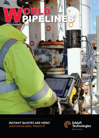
ON THIS MONTH'S COVER
®
Volume 22 Number 6 - June 2022
Reader enquiries [www.worldpipelines.com]
www.worldpipelines.com
Member of ABC Audit Bureau of Circulations Copyright© Palladian Publications Ltd 2022. All rights reserved. No part of this publication may be reproduced, stored in a retrieval system, or transmitted in any form or by any means, electronic, mechanical, photocopying, recording or otherwise, without the prior permission of the copyright owner. All views expressed in this journal are those of the respective contributors and are not necessarily the opinions of the publisher, neither do the publishers endorse any of the claims made in the articles or the advertisements. Printed in the UK.
ISSN 1472-7390
CBP006075
Eddyfi Technologies provides the highest performance NDT inspection technologies in the world, helping OEMs, asset owners and service companies enhance productivity, save lives, and protect the environment. Sonyks™ is the most advanced system commercially available that not only massively improves the efficiency of guided waves for conventional long range ultrasonic testing, but also has new capabilities for medium range ultrasonic testing for different pipe inspection applications. Visit www.eddyfi.com to learn more.
OFC_WP_June_2022.indd 1
30/05/2022 09:42
Complete Restoration. No Disturbance.
Non-invasive pipeline replacement technology Access difficult areas without environmental disruption Meet Environmental, Social, and Governance (ESG) standards Scan to learn more
Prepare for the energy transition
EDITOR’S COMMENT CONTACT INFORMATION MANAGING EDITOR James Little
james.little@palladianpublications.com
EDITORIAL ASSISTANT Sara Simper
sara.simper@palladianpublications.com
SALES DIRECTOR Rod Hardy
rod.hardy@palladianpublications.com
SALES MANAGER Chris Lethbridge
chris.lethbridge@palladianpublications.com
PRODUCTION MANAGER Calli Fabian
calli.fabian@palladianpublications.com
EVENTS MANAGER Louise Cameron
louise.cameron@palladianpublications.com
DIGITAL EVENTS COORDINATOR Stirling Viljoen stirling.viljoen@palladianpublications.com
VIDEO CONTENT ASSISTANT Molly Bryant molly.bryant@palladianpublications.com
DIGITAL ADMINISTRATOR Leah Jones
leah.jones@palladianpublications.com
ADMINISTRATION MANAGER Laura White laura.white@palladianpublications.com
Palladian Publications Ltd, 15 South Street, Farnham, Surrey, GU9 7QU, UK Tel: +44 (0) 1252 718 999 Website: www.worldpipelines.com Email: enquiries@worldpipelines.com
Annual subscription £60 UK including postage/£75 overseas (postage airmail). Special two year discounted rate: £96 UK including postage/£120 overseas (postage airmail). Claims for non receipt of issues must be made within three months of publication of the issue or they will not be honoured without charge. Applicable only to USA & Canada: World Pipelines (ISSN No: 1472-7390, USPS No: 020-988) is published monthly by Palladian Publications Ltd, GBR and distributed in the USA by Asendia USA, 17B S Middlesex Ave, Monroe NJ 08831. Periodicals postage paid New Brunswick, NJ and additional mailing offices. POSTMASTER: send address changes to World Pipelines, 701C Ashland Ave, Folcroft PA 19032
A
rthur D. Little’s recently published ‘Disruption is now’ report, declares that “a nation’s digital backbone must be thought of as a strategic asset – just like aviation, shipping, water, energy, and road and rail.”1 The report, which comes from ADL’s Energy & Utilities Practice, explains how the maturity of digital networks and the reliability of data connections are key to both economic growth and meeting SENIOR EDITOR Elizabeth Corner energy transition targets. elizabeth.corner@palladianpublications.com After an in-depth discussion of the energy resources and cleantech market segments, the report concludes: “It is evident that most companies in the energy and resources sector will need to go through a period of unprecedented change if they are to be fit-for-purpose in an increasingly decarbonised, decentralised, and digitalised world.” It continues: “For most, achieving greater operational efficiency by embracing digitisation will be the only way to develop the flexibility needed to quickly adapt to changing market conditions.” In the pipeline sector, smart connected devices enable remote monitoring and this, in turn, facilitates data analysis and predictive maintenance processes. Reliable operational data and diagnosis bring the kind of insight that can drastically change the way your company does business. On p. 14 of this issue of World Pipelines, Steffen Zendler (Rockwell Automation) writes about modernising pipeline operations and outlines how smart operations can enable seamless connectivity across an entire oil and gas operation. Rockwell Automation’s joint venture with Schlumberger (‘Sensia’) demonstrates the power of automation to connect and elevate the sector. Read the article for an interesting case study on Perenco, which found its distributed control system lacking and needed to make a tough decision on upgrading or replacing. Starting on p. 17, Alex de Joode (Head of Pipelines and Terminals Business Unit at AP Sensing and Chairman of the Technical Committee for the Fiber Optic Sensing Association [FOSA]) discusses distributed fibre optic sensing-based leak detection and location software (DFOS-PLDS) systems. The article analyses the applicability of these relatively new technologies within API standards and recommended practices. I also want to highlight this month’s hydrogen pipelines feature: starting on p. 33 we look at the feasibility of hydrogen pipeline transport. The special feature covers requirements for pipeline networks, repurposing existing infrastructure, gas blending, integrity and safety of pipeline steels, testing, financing, land rights and legislation. The ADL report states that: “The biggest challenge for energy networks relates to energy transition: dealing with new energy flows triggered by a growing number of renewable energy sources and having to handle new energy carriers in the energy system at large.” Hydrogen is increasingly being brought into the energy portfolios of oil and gas companies of all kinds. The hydrogen economy will require new business models, informed investments decisions and capable steering by policymakers. “Pipelines tend to be central to any integrated national hydrogen plan” according to the report, so, while we wait for demand to be secured, we must take steps to define and develop our respective strategies towards this fuel of the future. 1.
www.adlittle.com/en/insights/report/disruption-now
Dedication Innovation Integrity
Offshore
Onshore
Field Joint Coating and Custom Coating Services
Spoolbase
Custom Coating
Pipeline Induction Heat (PIH) provide specialist field joint coating services at spool base locations, offshore pipe lay barges and onshore pipeline construction projects around the world, involving the use of stateof-the-art equipment and processes for the application of a wide range of field joint coating materials. PIH also provide Custom Coating services for the application of the latest Thermal Insulation solutions (IMPP and IMPU) to bends and spools.
Pipeline Induction Heat Ltd, Burnley, UK Tel: +44 (0) 1282 415 323 E-mail: sales@pih.co.uk
Fax: +44 (0) 1282 415 326 Web: www.pipelineinductionheat.com
WORLD NEWS FERC approves new natural gas pipeline projects
Northern Goldfields Interconnect gas pipeline begins construction
The EIA’s recently updated ‘Natural Gas Pipeline Project Tracker’ tracks recently approved and completed natural gas pipeline projects. In 1Q22, the Federal Energy Regulatory Commission (FERC) approved three projects intended to increase US natural gas exports via pipeline and as LNG. The EIA’s tracker also lists pipelines that were completed last quarter. FERC approved two projects that connect to LNG terminals in Louisiana. The Evangeline Pass Expansion Project is a 1.1 billion ft3/d project owned by Tennessee Gas Pipeline Company. The project includes 13.1 miles of new pipeline and two new compressor stations that will deliver natural gas to the proposed Plaquemines LNG Project in Plaquemines Parish, Louisiana. The Alberta Xpress Project is a 0.17 billion ft3/d project owned by TC Energy that will use existing capacity on the Great Lakes Gas Transmission (GLGT) system and the ANR pipeline and will add a new compressor station in Evangeline Parish, Louisiana. The project expands capacity from the GLGT receipt point at the Minnesota-Manitoba border to delivery points in the US Midwest and US Gulf Coast, increasing the available capacity for LNG export facilities in the region. This project also improves the domestic natural gas infrastructure in those areas.
Work has begun on a 580 km, AUS$460 million pipeline in Western Australia (WA). The pipeline will take natural gas from the Perth basin out to resources projects in the state’s Goldfields and form a 2690 km gas pipeline network in WA, significantly increasing the volume of gas available inland. Infrastructure company, APA Group has started work about 50 km east of Geraldton, at the intersection of the Dampier to Bunbury pipeline. In the coming months, it will use up to 600 workers to construct the 30 cm dia. pipeline west to the Goldfields gas pipeline, south of Leinster. The project has been delayed due to authority approvals, but Gerard Coggan, APA General Manager of Infrastructure Planning and Approvals, hopes the project will be finished in March. “It is a logistically challenging project but it is something that APA and our principal contractor has done before,” Coggan says. “We’ve spent a couple of years planning this project, so we are looking forward to executing the project … and delivering gas to the Goldfields region.
Nanohana Pipeline completes construction Keiyo Gas Co., Ltd. (Keiyo Gas), Otaki Gas Co., Ltd. (Otaki Gas), JERA Co., Inc. (JERA), TEPCO Energy Partner, Inc. (TEPCO EP), and Nanohana Pipeline K.K. (Nanohana Pipeline) has held a ceremony to mark completion of the Nanohana Pipeline (NP), a pipeline for transporting natural gas in Japan. The NP is a high-pressure trunkline whose construction by Nanohana Pipeline – established by Keiyo Gas and Otaki Gas – began in 2018. The NP runs approximately 31 km from JERA’s Futtsu LNG terminal to the Anegasaki thermal power plant in Chiba Prefecture and will begin operating this June.
To ensure stable, efficient facility operation, JERA will assume operation of the NP from Nanohana Pipeline after launch and integrate its operations with those of JERA’s own power generation pipelines. Nanohana Pipeline will remain owner of the NP. Keiyo Gas, Otaki Gas, and TEPCO EP will use this pipeline to promote expanded use of natural gas. With completion of the NP, the five companies will contribute to the stable supply of natural gas while living up to the trust and expectations of customers and local communities.
USDOT accepts applications for Biden’s Bipartisan Infrastructure Law programme US Transportation Secretary, Pete Buttigieg has announced that the Department of Transportation’s Pipeline and Hazardous Materials Safety Administration (PHMSA) has begun accepting applications for its new natural gas distribution infrastructure safety and modernisation grant programme. The grant programme was made possible by the Bipartisan Infrastructure Law signed by President Biden on 15 November 2021. The programme offers nearly US$200 million in grants annually over the next five years to improve the safety of high-risk, leak-prone natural gas distribution infrastructure and create good-paying jobs, with an emphasis on benefiting underserved communities, in both rural and urban areas. “We’re announcing new funding to help communities of all sizes make their natural gas pipelines safer, create good jobs, and reduce the risks to residents, businesses, and our environment from dangerous accidents or leaks,” said US
Transportation Secretary, Pete Buttigieg. “This funding became available through the President’s Bipartisan Infrastructure Law, which we are hard at work implementing across every area of our Department’s responsibility.” The funding opportunity is open to all municipal or community-owned utilities (excluding for-profit entities) seeking assistance in repairing, rehabilitating, or replacing highrisk, leak-prone natural gas distribution infrastructure. Funds can also be used to acquire equipment that will assist in reducing natural gas distribution pipeline incidents and fatalities, as well as to avoid economic loss from leaks. “These grants will help communities upgrade piping that in some cases is older than any American alive today,” said PHMSA Deputy Administrator, Tristan Brown. “All eligible entities are encouraged to apply, with a focus on projects that will have the greatest benefits for the communities that need the most support.”
JUNE 2022 / World Pipelines
5
CONTRACT NEWS EVENTS DIARY
Global oil and gas contracts stifled in 1Q22
19 - 23 September 2022
At the start of 1Q22, global oil and gas industry contract activity was stifled due to the Russia-Ukraine conflict. However, in the second half of the quarter a minor increase in the number of contracts was reported. Unfortunately, the industry was unable to maintain its position in terms of contract value compared to the previous quarter, according to GlobalData, a leading data and analytics company. Pritam Kad, Oil & Gas Analyst at GlobalData, comments: “Contracts in the oil and gas industry could only float due to the sheer uncertainties surrounding it, including the ongoing Russia-Ukraine crisis, rising prices, and project cost escalation. However, Saudi Aramco was able to keep the momentum going with Zuluf oilfield expansion contracts during the quarter.” GlobalData’s latest report, ‘Q1 2022
Prague, Czech Republic
Strohm and Lhyfe join forces
7 - 9 June 2022
Global Energy Show Calgary, Canada www.globalenergyshow.com
14 - 15 June 2022
Hydrogen Technology Conference & Expo Houston, USA www.hydrogen-expo.com
5 - 8 September 2022 Gastech
Milan, Italy www.gastechevent.com
IPLOCA 2022 annual convention www.iploca.com/events/annualconvention/2022-convention
27 - 29 September 2022 IPE 2022
Calgary, Canada internationalpipelineexposition.com
19 - 20 October 2022
Hydrogen Technology Expo Bremen, Germany www.hydrogen-worldexpo.com
24 - 30 October 2022 bauma
Munich, Germany https://bauma.de/en
31 October - 3 November 2022 ADIPEC
Abu Dhabi, UAE https://www.adipec.com
6
World Pipelines / JUNE 2022
Strohm, the world’s first and leading manufacturer of fully bonded, thermoplastic composite pipe (TCP), has signed a memorandum of understanding (MoU) with French renewable hydrogen supplier, Lhyfe. The collaboration will see the two companies working together to develop solutions for hydrogen transport, both onshore and offshore, with initial plans to launch the first floating wind turbine to be integrated with a hydrogen production system. Lhyfe’s Nerehyd solution, a concept worth approximately €60 million, including research, development, and the production of the first prototype in 2025, incorporates a hydrogen production facility on the floating platform, connected to a wind turbine. The concept is adapted to on-grid or off-grid applications, from single wind turbines to large-scale wind farm developments. Strohm is the market leader in the design and manufacture of TCP, which is particularly suited for carrying hydrogen offshore and subsea. Produced at its plant in the Netherlands, the corrosion-resistant technology does not fatigue or suffer from issues associated with using steel pipe for hydrogen, such as embrittlement. Manufactured in long spoolable lengths and flexible in nature, the pipe can be pulled directly into the wind turbine generator, quickly and cost effectively building an offshore wind farm infrastructure.
Global Oil & Gas Industry Contracts Review’, reveals that the number of contracts saw a minor increase from 1452 in 4Q21 to 1546 in 1Q22. However, overall contract value decreased significantly from US$61.16 billion in 4Q21 to US$36.93 billion in 1Q22. In terms of single scopes, operation and maintenance (O&M) represented 56% of the total contracts in 4Q21, followed by procurement with 16%, and contracts with multiple scopes, such as construction, design and engineering, installation, procurement, and O&M accounted for 14%. A notable contract during the quarter was Saudi Aramco’s award of multiple contracts for the expansion of the Zuluf oilfield in Saudi Arabia, including EPC work to JGC Holdings ranging between US$2 and US$2.5 billion.
THE MIDSTREAM UPDATE •
7% increase in oil and gas pipelines incidents in UK
•
STATS Group post 17% revenue increase to £49.7 million
•
Asset Guardian Solutions achieves ISO/IEC 27001 Certification
•
Honeywell announces Safety Watch real-time location solution
•
Equinor exits all Joint Ventures in Russia
Follow us on LinkedIn to read more about the articles linkedin.com/showcase/worldpipelines
PETROLATUM TAPE SYSTEMS
BITUMEN & BUTYL TAPES
SOIL-TO-AIR INTERFACE SYSTEMS
PROTAL 7200™ SPRAY/ROLLER/BRUSH APPLIED LIQUID EPOXY COATING
PROTECTIVE OUTERWRAPS
DENSO VISCOTAQ™
> A range of viscoelastic tapes used for corrosion prevention on pipelines, field joints, fittings & valves. > The unique, self-healing technology of Viscotaq offers asset owners outstanding, long-term protection against corrosion.
DENSO™ are leaders in corrosion prevention and sealing technology. With over 135 year’s service to industry, our mainline and field joint coating solutions offer reliable and cost effective protection for buried pipelines worldwide.
United Kingdom, UAE & India USA & Canada Australia & New Zealand Republic of South Africa
www.denso.net www.densona.com www.densoaustralia.com.au www.denso.co.za
FOR CORROSION PREVENTION
A MEMBER OF WINN & COALES INTERNATIONAL
Cesare Bianchi, Project Engineer, MAX STREICHER S.p.A., Italy, discusses the use of pilot drilling, raise boring, and microtunnelling within the Italian pipeline network.
O
n behalf of Snam Rete Gas S.p.A. MAX STREICHER S.p.A., the Italian subsidiary of the German STREICHER Group has carried out a 32.4 km long section of the Rimini-Sansepolcro pipeline. The new DN 750 (30 in.) pipeline replaces an existing DN 650 (26 in.) line and mostly traverses mountainous and geologically difficult terrain that is hard to access. Through meticulous preparation efforts, it has been possible to make good progress in a short span of time; work began May 2020 using efficient drilling procedures along many trenchless pipeline sections. The approximately 75 km long pipeline between the communities of Rimini (Emilia-Romagna) and Sansepolcro (eastern Tuscany) constitutes an important connecting section of the Ravenna-Chieti and Montelupo-Sansepolcro courses within the Italian pipeline network. A new and larger gas pipeline is being planned for future developments of the network; this will ensure gas is transported more flexibly between the eastern and western parts of the country. Another benefit to this project is the increased safety in transportation, as the use of modern pipeline laying techniques ensures the pipeline is installed safely even in geologically challenging sections of the traversed terrain. Snam Rete Gas has commissioned STREICHER with one out of three construction lots. This includes the construction of a 32.4 km long DN 750 pipeline section including four valve stations, a short section DN 650 pipeline and three DN 100 secondary pipelines with a length of 2.3 km. Numerous crossings, which were mainly executed with trenchless technologies, have also been part of the project. The new gas pipeline largely traverses on its existing route, specifically along the alluvial plain of the upper Tiber Valley. In various other sections of the pipeline, deviations and route optimisations were unavoidable, as local conditions prevented a re-laying of the line directly adjacent to the existing pipeline. “A large section of the pipeline route leads across the Apennines, a mountainous area with sand and calcareous rock composition. The slopes here have an average gradient of more than 44.5% and are usually forested. Because the pipeline route here mostly runs along the ridges of the hills, we had to cope with some very steep sections and, among other things, take protective measures against falling rocks,” explains Samuele Luzietti, Project Manager.
Detailed construction site planning and expansion of access roads In order to minimise risks related to the composition and texture of the rock, geognostic surveys were carried out in advance. In addition, STREICHER worked on a detailed
8
8
Figure 1. Poggio della Travaia microtunnel – site layout.
9
construction site plan (ROW project) for the laying works on the mountain ridges. It includes an exact recording of the relevant sections (a total length of around 12.3 km), the areas with terrain layers to be removed and the designated volume of material to be required. The planning of stabilisation measures (i.e. concrete bored piles), which serve as supporting elements during and after the construction work, has also been part of the ROW project. In addition to the many narrow terrain strips available for construction work on the hills, often only 10 - 12 m wide, it has been another challenge to gain access to them at all. There had only been very few access roads in the area where steep slopes and abruptly interrupted paths had been making it difficult to get through. This also was the case with many of the sections where the pipeline had to be laid with trenchless technologies. In the initial phase of the project, STREICHER therefore expanded the existing roads, paths and trails to such an extent that they became traversable even for construction vehicles. When scheduling all work on the pipeline, STREICHER had to take a number of factors into account. Among other things, the accessibility of construction routes during the winter months had been playing an important role. Temporary access bans to nature reserve areas, such as along the construction sections of ‘Alpe della Luna’ and ‘Marecchia’ (an imposed four-month closure during the spring/summer season), where complex crossings had to be executed, needed to be observed. A further obstacle was added by the COVID-19 lockdown, which lasted several months, meaning work onsite could not start until the
Figure 2. Automatic welding.
10
World Pipelines / JUNE 2022
end of May 2020. In order to be able to still meet the agreed deadlines, a decision was made to process several construction activities in parallel. A focused attention was given to the execution of special structure, such as two sub-vertical boreholes and the laying of some very long and trenchless pipeline sections while using the microtunelling method.
Application of the raise boring technique at two sections A particular challenge had been the planning, preparation and execution of two raise boreholes. This method had been chosen because of the special geomorphological formations of the concerned sections – in this case it was the steep gradient of the areas that needed to be traversed. The sub-vertical method was made applicable as the construction sites had a stable and self-supporting rock formation. This avoided the need to find a longer alternative pipeline route or to perform the excavation of steep slopes for pipe laying that would require a subsequent surface restoration work. Among the aims and advantages deriving from the application of the raise-boring technique, the preservation of the environmental integrity of valuable and protected naturalistic areas is also important. In particular, the raiseboring Viamaggio has been realised inside the SIC/ZPS ‘Alpe della Luna’ as one of the most important areas of uncontaminated naturalistic value in central Italy. The process sequence during the execution of the raise boring method was essentially divided into three drilling phases and an installation phase, which is explained by using the example of the ‘Viamaggio’ section: first, a 163 m long pilot drilling was executed with an inclination angle of 45˚and a diameter of 10 in. from the summit crest along the axis of the sub-vertical borehole. A 288 m long horizontal base tunnel was built in accordance with the topographical survey made of the arrival point prior to the pilot drilling. It was driven at the base of the escarpment through the rock formation to the arrival point of the pilot drilling. Originally, this structure should have been established by employing traditional drilling technology and by the use of explosives. However, STREICHER suggested
STATS GROUP Managing Pressure, Minimising Risk
BISEP®
Hot Tapping & Plugging
PRODUCTION MAINTAINED
DUAL Leak-Tight Seals double block & bleed isolation SINGLE HOT TAP POINT
ISOLATED PIPELINE ZERO-ENERGY ZONE
The BISEP® with extensive track record provides industry first double block and bleed isolation while maintaining production. Hydraulically activated dual seals provide fully monitored leak-tight isolation, every time, any pressure.
designed launching head, which was held in position by a steel cable. The cable was attached to a 150 t heavy-duty winch, which stood on a suitably dimensioned concrete slab that was securely anchored in the ground. For installing purposes positioning the winch required a pulley to deflect the rope 90˚. In order to provide the necessary retention strength, one anchor block was made of concrete. Additionally, a steel frame with two additional deflection pulleys was built around the borehole, to which the short end of the steel cable could be firmly and stably anchored. The winch was then used to lower the launching head, by and by, deep enough into the borehole until the rear part of the casing pipe still protruded from the hole at around 1.5 m. Then the second pipe was moved with a crane to the same spot and welded manually to the first pipe. The launching head was then lowered a few meters further down. This process was repeated until all the casing pipes were connected, and the launching head had reached the bottom of the borehole. After the annular spacing between the borehole and the casing pipe had been filled, the DN 750 pipeline pipes were installed into the casing pipes by using the same method. When the sub-vertical pipe construction was completed, STREICHER installed the pipeline in the horizontal base tunnel and connected the main pipeline to the sub-vertical section via a connecting piece. To complete these complex tasks on time, on the two different sub-vertical borehole sections (the same TBM had to be used both times), work sometimes had to be carried out in several shifts and 24 hours a day.
Figure 3. Launching head with welded first piece of pipe.
Figure 4. Preparing the pipe installation from the ridge: anchor block (left) and steel frame (middle) with pulleys.
to its client to use a tunnel boring machine (TBM) with a removable shield. This method saved a considerable amount of time and also ensured a higher level of working safety during the procedural work. In a third step, a reamer was installed in the connecting chamber between the two boreholes and the pilot drilling was then widened from bottom to top to a desired diameter of 1800 mm. The resulting rock material was then transported through the horizontal tunnel to the outside.
Complex pipe installation from top to bottom The next step was to install the DN 1050 casing protection pipes into the sub-vertical hole, namely from top to bottom. At the beginning, the first pipe was welded to a specially
12
World Pipelines / JUNE 2022
Long and steep microtunnels successfully completed
In addition to the raise borings, the pipeline project also included several other crossings: in addition to two water crossings in an open construction method, STREICHER carried out 11 thrust borings, two HDD drillings, five microtunnels with steel pipes and further seven microtunnels with reinforced concrete pipes. Three of these microtunnels were not only particularly long (1256 m, 982 m and 820 m), but also challenging due to geological soil conditions. As the tunnel boring head was in danger of getting stuck, it was necessary to foresee a switch to the TBM Segmental Lining Tunnel method in case of necessity. In order to guarantee a successful drilling, STREICHER set up a push-module unit system specially designed for microtunnels with an internal diameter of 2000 mm. Another difficulty arose when installing the pipeline in some microtunnels with particularly high gradients of
Product focus: electrically driven welding tractors
Figure 5. Poggio della Travaia microtunnel.
up to 18%. In these cases, the pipeline was installed by using a winch and appropriately designed collars upon making the calculation of the maximum stresses expected during installation. Despite the project’s great complexity, STREICHER has managed to entirely complete its part of the pipeline project by May 2022. This means that the contractually agreed deadlines for the completion of all construction phases have been significantly overfulfilled in good timing. Particularly, it was between 30 and 60% fewer calendar days that were required than originally planned. It is only the dismantling of a 15 km section of the old DN 650 pipeline that is still pending. This task can only be carried out once the other two building sections of the new pipeline have been completed. They are expected to be available by August/September 2022.
Crossings performed in lot 2 of the pipeline )) 11 thrust borings, total length 392 m. )) Seven microtunnels with steel concrete pipes, total
length 4221 m. )) Five microtunnels with steel pipes, total length 494 m. )) Two raise borings, total length 877 m. )) Two HDD drillings, total length 608 m.
Coming to MAX STREICHER S.p.A.’s construction vehicle unit; electrically driven welding tractors for onsite pipeline construction projects, providing increased energy efficiency, operational safety and savings on resources. This innovative technology has originated from our parent company, MAX STREICHER GmbH & Co. KG aA, which has been developing electricdriven construction vehicles under the label of ‘ecotec’. The STREICHER Group has already leased and sold these items, and successfully employed them on our company-run building sites. Our portfolio includes the all-electric horizontal drilling rig HDD 80-E, which has proven itself in several projects, as well as the HDD 45-E, which is currently under construction. Both versions have been developed by an interdisciplinary team from STREICHER, just as with our welding tractor, together with our inhouse participation of experienced device operators. An important feature of our drilling rigs is their fully electric drive systems; both CO2 emissions and noise pollution can be significantly reduced, which is a great advantage when used in nature reserves and populated areas. Systems can be supplied by the public power grid, while a built-in energy storage device allows stored energy to be accessed whenever required. Due to an intuitive operating concept and large operating touch panel, the system units also provide a good overview of the drilling process and its drilling parameters. The HDD80-E has already won some awards IPLOCA New Technologies Award 2021, IPLOCA Health & Safety Award (Runners Up) 2021 and the Red Dot Design Award 2022 category ‘Excellence in Business to Business - Machines & Engineering’. The PW 150-E welding tractor is similarly innovative and has been redesigned completely; it features an electric drive system with two electric motors that significantly reduces the system unit’s energy consumption and operating and maintenance costs. Its new chain units ensure a larger footprint that reduces the ground pressure of the tractor, whilst a radio remote control operation provides the vehicle operator with an excellent field of vision and high level of safety. STREICHER also offers all its machines of the ‘ecotec’ series to external customers in the construction industry.
)) Two river crossings, total length 1112 m.
JUNE 2022 / World Pipelines
13
14
Steffen Zendler, Rockwell Automation, Germany, discusses how modernising pipeline operations can enhance flexibility, data management and security.
P
ipelines continue to offer the best cost advantages for shipping oil and gas. As a result, recent industry estimates say that within the next 20 years, in the US, there will be 264 000 miles of new pipeline and 12 million additional horsepower in compression and pumping. Pipelines operators face a myriad of challenges in the energy transition, including reliability, compliance with regulations, safety, and sustainability. While juggling that quartet of challenges, they must improve operational efficiency to maintain profitability in the volatile and financially constrained market in which they operate. Increasing the complexity is the wide dispersal of assets that are invariably located in remote and inaccessible locations. And once the well is producing, they are often unmanned. The answer to these problems is automation. It is a path that the pipeline sector has been on for many years but the recent pandemic that has curtailed travel has heightened and hastened the process. Improvements in production can translate into increased efficiency and productivity. Whether the aim is to reduce energy consumption, upgrade legacy systems, or make better use of the data available, the road leads to modern automation. Sensia, a joint venture between Rockwell Automation and Schlumberger, is a comprehensively integrated provider of measurement solutions, petrotechnical expertise, automation and digital solutions to the oil and gas industry. From the reservoir to the refinery, Sensia uses Rockwell Automation technologies to reduce risk, drive efficiency, and optimise
performance, so that clients and their stakeholders can achieve the full potential of their oil and gas assets.
Dealing with legacy systems More than 2.2 million miles of oil and gas transmission pipelines are in place today in more than 120 countries. However, many pipelines are several decades old. For example, there are more than 300 000 miles of gastransmission pipelines in the US, one-third of them installed before 1960. Many of these oil and gas wellheads have been producing hydrocarbons for more than 20 years and you are more likely to come across manual valves than you are connected equipment. This reliance on legacy equipment has traditionally presented a formidable roadblock to attempts to automate the process, but the availability of inexpensive, connected sensors that can easily be added to older equipment has increased the possibilities. This ability to remotely monitor wellheads and pipelines is particularly important in this age of heightened environmental awareness. Back when these facilities were first constructed, environmental regulations were exceedingly rare, and spills or leakages were less of a problem. Today there is no hiding. When there is investment to update these sites, it starts with modernisation on the control side, which begins with smart sensors that have capability of data transfer to enable remote monitoring. That has all changed for new installations as modern pipeline equipment, such as pumps and compressors, are smart connected devices, many of which are monitored by the manufacturers to facilitate data analysis and
15
predictive maintenance strategies. The manufacturers, however, limit their attention to equipment level, but for process optimisation it is important that operations are viewed at a system level.
The connected control room Pipeline operators need accurate, real-time, and easy-to-understand data to be effective in their jobs. Using enabling technologies and the IIoT, operators can collect critical operational data, contextualise it into easily understandable and actionable information, and deliver to operators in real-time to improve reliability and decision-making. Altogether, this deeper and realtime asset visibility can help operators track and respond quickly to maintenance, operation, and flow-control issues. Now, with data readily available, it is all about creating interfaces that allow this data to be collected, assimilated, and transferred to the remote control centre, to create a single version of the truth. The aim is to create a smart pipeline network that is a modern, secure, and information-enabled infrastructure connecting intelligent assets and sharing information across your pipeline and beyond. A smart pipeline consists of seven elements: multidiscipline control, AC drives and MCCs, condition monitoring, turbo machinery control, secure network infrastructure, mobile and open information platform, and operations intelligence software. The Columbia Pipeline Group runs nearly 15 000 miles of natural gas pipelines in the US and serves customers in 16 states – from the Gulf Coast to the Northeast. To improve pipeline reliability and throughput, the company launched a five-year plan to modernise the control system and compression stations across its network. The company met its goal by standardising on one platform – PlantPAx DCS on virtualised servers, installing redundant horsepower and implementing Rockwell Automation Power Control solutions.
A convergence of data The concept of IT/OT convergence has long appealed to executives in the sector. Connecting the process control, measurement, and safety systems at production sites with IT infrastructure and applications enables remote connectivity for highly valuable realtime data and remote support. Yet, in practical terms, this goal has been hard to achieve due to the rugged, dislocated and often remote nature of oil and gas operations. Now, as the sector navigates short-term volatility and longerterm structural changes, integrating IT and OT has been elevated to a critical consideration for decision makers in seeking to maximise the value of their production operations. True IT/OT convergence is multi-dimensional. In a typical production environment, there are multiple types of systems that can be integrated. On the operating side, there are the control and safety systems, measurement, and other infrastructure, while on the business side there are standard applications such as visualisation software and back allocation reporting. There is also a need for convergence within these realms, ensuring joined-up data, communication, and workflows across systems.
Advanced automation in action The challenges that pipeline operators face was highlighted in a project with Perenco. The European independent gas producer had a race against the clock to bring integrated control and safety
16
World Pipelines / JUNE 2022
systems (ICSS) in its process control facility operation, or else face dire consequences for delays. Rather than constructing a fixed gas well from scratch – a process that can take many years to complete – Perenco decided, in 2015, to allow the roll out of the world’s first example of a floating liquidation vessel (FLNG), built from a converted ship, at its Sanaga gas production operation, which fuels the Kribi power station in south-west Cameroon. Named the Hilli Episeyo, the ship not only shaved years off the commissioning process but has created a more adaptable way to retrieve gas from stranded gas reserves, in compliance with national legislation. The Sanaga offshore operation is controlled from Perenco’s Bipaga onshore gas central process facilities (CPF). The Bipaga facility receives natural gas from Sanaga and, after processing using low-temperature treatment, delivers LNG condensate and LPG as byproducts. These facilities allow Perenco to produce 1 200 000 t of LNG for exporting, and 26 000 t of domestic gas to fuel Cameroon’s households. The company’s previous distributed control system (DCS) was beset by several challenges. Firstly, the process and safety elements were misaligned, bringing operational inefficiencies. Secondly, the lack of diagnostic information meant that trained staff were required onsite to identify and address issues. Thirdly, the platform lacked the scalability to expand capacity, which was coming under pressure as operations in the Sanaga gas field grew. The challenges were evident during a particular incident. A network issue was identified at a late stage, requiring specialist engineers to be brought to the site. Resolving the problem meant a week of downtime and sizable costs, highlighting the urgent need for a greater degree of systems autonomy and faster turnaround in resolving issues. This left Perenco with a choice: either upgrade the existing system or replace it entirely. Following deep analysis, the company decided to transition from the DCS to an ICSS connected to Perenco’s centralised data operations, and to remote access points in Douala and Paris, Perenco’s local and central HQ respectively. These new requirements led to Perenco awarding the contract to our long-term partners ITEC Engineering, who brought in Rockwell Automation to help cover the full scope of the project – from electrical and instrumentation, through to integration of the plant ICSS. One year on from the implementation, Perenco has already realised some important benefits that justify the decision to transition from its original DCS. These include enhanced scalability, improved integration capabilities, greater simplicity, and better diagnostics.
The future is smart and connected Modern smart operations driven by the IIoT unite people, processes, and technology in an integrated network architecture. Modern systems help converge business-level IT systems with station and terminal-level operations technology systems to enable seamless connectivity across an entire oil and gas operation – from the pipeline to the oilfield, and processing plant to the enterprise. Smart operations use the latest integrated control and information solutions to collect operational data and deliver it to workers as actionable intelligence.
Alex de Joode, Chairman of the Technical Committee at FOSA, and Head of Pipelines & Terminals Business Unit at AP Sensing, Germany, discusses the applicability of distributed fibre optic sensing based pipeline leak detection software under API 1130 and API 1175.
T
he 2022 revisions of API 1175 (Pipeline Leak Detection – Programme Management) and API 1130 (Computational Pipeline Monitoring for Liquids) included many essential updates. The current state-of-the art pipeline leak detection methods were reviewed, including the contribution of distributed fibre optic sensing (DFOS) technologies. DFOS based pipeline leak detection and location software (DFOS-PLDS) is possibly the most important technological development in pipeline leak detection in recent years. Despite being a relatively new technology, DFOS-PLDS is already applied to an extensive number of pipelines covering a wide variety of pipeline conditions. DFOS-PLDS’s fast adoption is a testimony to the benefits it can provide. Despite not prescribing specific pipeline LDS methods, Pipeline and Hazardous Materials Safety Administration (PHMSA) recently listed ‘fibre optic based distributed sensing’ as a type of continuous pipeline monitoring in a November 2021 ruling. DFOS is a technology that can transform fibre optic cables into sensing cables, enabling close monitoring of long assets such as pipelines, power cables, roads, tunnels, or rail lines. DFOS-PLDS uses the measurements from one or more DFOS interrogators. DFOS-PLDS algorithms confirm detection and calculate the location of leaks, avoiding false positives. Associated software can also provide temperature measurements, third party interference monitoring, or pig tracking.
17
DAS based NPW CPM brings several benefits for the sensing of NPWs: Resilience to obstacles to the NPWs path Point sensors are normally installed many kilometers apart, and NPW propagation can be interfered with or stopped entirely by these obstacles. Pressure-regulating valves, pigs, slack-flow vapour pockets, changes in diameter, booster stations, manifolds and other factors can interfere with Figure 1. Typical V shaped profile showing the NPW point of origin at approx. 1300 m and propagation along the 1800 m pipeline segment. Courtesy of Optasense. or prevent the arrival of an NPW to a remote pressure Several different technologies are encompassed by sensor. DFOS ensures sensitivity along the pipeline. different ‘fibre optic based distributed sensing’, with DTS (distributed temperature sensing) and DAS (distributed Pressure wave attenuation acoustic sensing) being the two most commonly used Pressure wave attenuation is a limiting factor that restricts DFOS for pipeline leak detection. Both DTS and DAS can be the maximum distance to a remote sensor. Distributed implemented on their own or in combination. sensing delivers sensors at closer proximity to the leak origin and therefore provides greater sensitivity even with DAS DFOS-PLDS and 2022 edition of API 1130 interrogators placed 100 km apart. Negative pressure wave (NPW) LDS based on DFOS (DAS in particular) has been used for some time now, and can provide Event duration and confirmation significant improvements over pressure meter based NPW DAS can monitor not only the onset of NPWs, but also the CPM (computational pipeline monitoring). Similarly, Acoustic progress of the NPWs as they travel over many kilometers. LDS software based on distributed sensing represents a NPW monitoring time using DAS is therefore much longer significant improvement on a CPM based on an array of than using point sensors, clearly showing travel direction and single-point sensors. point of origin (see Figure 2). The 2022 edition of API 1130 no longer limits the type of sensor used for NPW/Acoustic CPM. The new text removed DAS based Acoustic CPM the implicit requirement for the sole use of pressure meters The continuous flow through the leak orifice generates to detect negative pressure waves and acoustic signals. acoustic signals inside and outside the pipe and produces Instead, the new text refers more generally to ‘sensors pressure instabilities within the fluid. Acoustic CPM has capable of detecting’ such signals. The new text also clarifies historically been based on special transducers capable of that the previous NPW/Acoustic CPM are two different LDS capturing the frequencies produced by the leak event. These methods based on the detection of two different physical acoustic signals are present throughout the duration of the phenomena. NPW and Acoustic CPMs are now defined in leak, not only at the onset but are weaker than signals from Annex B as two separate CPMs (B5 - Negative Pressure Wave NPWs and attenuate faster. The proximity of the DFOS CPM; and B6 - Acoustic CPM). sensor cable provides a much greater probability of detecting acoustic leak signals than sensors placed kilometers apart. DAS based Negative Pressure Wave CPM DAS based PLDS are used to identify the acoustic signals NPWs are rarefaction waves generated during the onset of and general signal behavior to classify leaks and avoid false the leak. NPWs propagate in the fluid at the speed of sound positives. in both directions away from the leak origin. NPW CPM software has historically relied on instrumenting multiple DFOS technologies and API 1175 locations with two pressure meters, to determine the timing The API 1175 Recommended Practice (Pipeline Leak and direction of the propagation of such waves. In the Detection – Programme Management) addresses many PLDS case of DAS based NPW CPM, the information provided by programme components. The 2022 edition discusses the the fibre optic cable is used to determine NPW origin and main LDS methods, selection process methodology, and observe the 2 NPWs travelling many kilometers away from their applicability within the LDS program, among other the leak position (see Figure 1). programme elements.
18
World Pipelines / JUNE 2022
DFOS-PLDS can support the Pipeline Leak Detection Programme as Primary LDS, Complementary LDS, or Alternative LDS (in case the Primary LDS is not in service). DFOS-PLDS could also be present as a Redundant LDS, provided it has the same functions as the Primary LDS.
Primary LDS The pipeline operator may define different Primary LDS for specific operational conditions, like startups, shut-in or slack flow. An API 1130 CPM technique is typically the Primary LDS; however, an externally based LDS may be deemed more appropriate in some instances. The 2022 revision of API 1175 incorporates an example of the external LDS performance table format. DFOS-PLDS can be considered part of an API 1130 (NPW and Acoustic CPM). It can also be the Primary LDS as an
external LDS, typically using DTS or distributed temperature gradient sensing (DTGS). DTS and DTGS are often considered Primary LDS for pipeline applications where leak events generate a fast and strong thermal effect. In these cases, and especially for small diameter pipes, the DTS/DTGS based PLDS software alarms are easy to understand. They can provide a very sensitive, reliable method with unparalleled performance. In certain applications, DTS/DTGS monitoring solutions can be engineered to provide fast alarm response with the accurate temperature and location readings required from a primary LDS.
Complementary LDS DFOS-PLDS can be one component of a multi-LDS system to assist the Primary LDS. Industry recommended practices state that a combination of leak detection methods should be considered to improve the leak size detection threshold, reduce the time to detect a leak, and/or define the leak location more accurately. Some factors to consider in selecting a Complementary LDS: • DFOS can provide the leak location to within a few meters, and an accurate leak location can reduce confirmation and response time. • Leak confirmation from a fundamentally different LDS technique may increase the operator’s confidence to take action, further reducing response time. DFOS will not share the same sources of false positives like field measurement inputs, calibration errors and flow imbalances due hydraulic transients. • Small leak rates, if left undetected, can lead to large leak volumes, requiring periodical leak survey methods to be detected. PLDS during shut-in can in principle, detect small leak rates in liquids, but pressure based systems might not locate the leak position during shut-in if the leak started during flow. • Slow-release, growing leaks may not generate NPWs.
Figure 2. DAS give a unique insight showing multiple NPWs generated by the traveling PIG. The NPWs progate at approx. 1000 miles/hr (450 m/sec.) on a 45 km gas pipeline. Courtesy of AP Sensing.
DFOS-PLDS is, in most cases the ideal Complementary Continuous LDS and can also be considered to replace some non-continuous LDS
Table 1. Example of a Leak Detection Programme including DFOS-PLDS Non-continuous LDS
Continuous LDS Leak rate type
SCADA monitoring
Public awareness
Aerial surveillance
Noncontinuous DFOSPLDS
Inline inspection
Rupture
•
•
•
•
•
•
N/A
Medium leak
O
•
•
•
•
•
•
Small leak
X
O
•
O
O
•
•
Seep
X
X
O
O
O
O
•
X O
20
Continuous DFOSPLDS
CPM
World Pipelines / JUNE 2022
methods used to detect seeping leaks. Table 1 shows where DFOS-PLDS can be used for different leak rates.
variations are consistent with a leak and not caused by normal environmental variations or by the pipeline thermal transients.
Redundant LDS
DTGS – distributed temperature gradient sensing – (part of DAS)
DFOS-PLDS can be designated as a Redundant LDS, i.e., it has the same function as the Primary or Complementary LDS. In case of failure, the Redundant PLDS runs in parallel or takes over automatically. In addition to duplicated systems, some LDS method combinations using DFOS-PLDS could be considered redundant: • DFOS-PLDS based on DTS and DTGS, when used together, could be considered a redundant configuration. • Pressure based NPW CPM and DFOS based NPW CPM.
Measures temperature variations very quickly over finite time spans. The DFOS-PLDS based on DTGS will alarm based on significant temperature variations in the environment outside the pipe. The DFOS-PLDS will apply algorithms and numerical techniques to analyse if the temperature variations is consistent with a leak and not part of normal variations. Detection of acoustic and pressure wave signals include:
DFOS-PLDS technologies The main DFOS-PLDS technologies can be grouped according to thermal, acoustic and pressure wave detection capabilities. Detection of thermal signals include:
Raman & Brillouin DTS – distributed temperature sensing Measures accurate temperature values and temperature variation. The DFOS-PLDS based on DTS will alarm based on temperature values or significant temperature variations in the environment outside the pipe. The DFOS-PLDS will apply algorithms and numerical techniques to analyse if the temperature and temperature
DAS – distributed acoustic sensing
DAS interrogator analyses of backscatter light can sense minute dynamic changes in fibre length caused by vibrations, sound waves, pressure pulses, and temperature variations. DAS providers use different DFOS-PLDS software to analyse and classify these transient signals to determine whether these signals are compatible with NPWs propagation due to leak events, or caused by background noise.
Conclusion The benefits of DFOS-PLDS should be considered either as part of API 1130 or as part of API 1175 External PLDS. DFOSPLDS can be used to fulfill various roles within API 1175 (Primary, Complementary, Alternative or Redundant) LDS.
IPLOCA - offering opportunities for industry leaders to network and collaborate on a global level
54th IPLOCA Annual Convention, ‘Pipelines Powering a Sustainable Future’, 19-23 September 2022, Prague, Czech Republic
visit www.iploca.com to find out more
International Pipe Line & Offshore Contractors Association Geneva - Switzerland
T
he goodwill and enthusiasm of the COP26 summit to do the right things for future generations would appear to have broad agreement and support from international governments. A move away from the energy sources that have adverse impacts to the climate is most likely inevitable, but is clearly a highly complex and challenging task to achieve. In a recent media article, Pulitzer Prize energy author, Daniel Yergin stated history has demonstrated energy transitions take time to achieve, and do not necessarily completely sever the dependence from the status quo.1 The global reliance on oil and gas is not simply just as an energy source, but also the derivatives for materials and products that are used daily. It is certain to take time to unwind from this. As Elon Musk stated through gritted teeth, “Solutions to maximise natural resource output will be necessary to meet current energy demand and support such transition”. Secondary to the human crisis in Ukraine, energy supply issues and energy poverty now dominate the headlines. In a similar way to the geopolitical energy crisis of the 1970’s, the current situation in Eastern Europe has sparked countries to re-evaluate their energy security. The recent UK government announcement to address a baseload electrical supply of 24 GW via nuclear power by 2030 is still some way distant. In addition to this, in what may seem an obvious strategy, has been the broad support to encourage the development of the remaining national oil and gas reserves. In the UK, most
hydrocarbon operators have taken a commitment to explore and produce these natural resources efficiently with lower emissions. For new field development, the UK Oil and Gas authority (OGA) requires developers to submit comprehensive plans on the practical steps they will take to make any new development net-zero emissions for the complete lifecycle of the asset. This is in addition to the current legislative compliance for an Environmental Impact Assessment (EIA). With the price of a barrel currently >US$100, and investment capital seeing more certainty on a
Donald Ballantyne, Business Development Manager, Tracerco, UK, discusses balancing the challenges of scaling up cleaner energy sources with the need for national economies to recover.
23
quick return, exploration drilling, subsea tieback and field redevelopment may bring forward another peak of activity, but this still brings cost and risk to projects being approved and sanctioned.
Achieving flow assurance Existing infrastructure and production hubs will be a critical part of such a ‘mini boom’. The integrity of structural and pressure systems will be at the core. In mature basins such as the North Sea, much of the remaining reserves are in smaller isolated (stranded) locations. The pipeline network will be essential to connect the pockets to realise field viability and value. With many systems in late life and beyond original design parameters, material degradation will require consistent and accurate direct methods of measurement to provide confidence in the assessments and predicted remanent life. With the double dip recession and low oil price, existing assets that were experiencing flow assurance issues were often shut in as the economics of remediation or replacement were prohibitive. In the current climate, addressing the challenges of blocked or restricted flow of pipeline infrastructure has potential to increase throughput significantly for relatively low investment. Providing solutions to such flow assurance issues are now a substantial proportion of Tracerco’s operational projects.
Inspection challenges Exploration for offshore oil and gas has driven forward the development of innovative technology to solve the challenges of inspection and integrity assessment. Over many decades, Tracerco has built a strong track record as subject matter experts on the use of ionising radioactive physics to perform static, dynamic diagnostic and specialist measurements from reservoir to downstream. This foundation expertise was used as the challenges to inspect and monitor went subsea, first shallow then to ultra-deepwater. Tracerco is proud to have set several benchmark technologies in this challenging market sector. Flooded member inspection (FMI or FMD) continues to provide a rapid and accurate method to quantify impact to structural integrity of jacket structures without the need for cleaning of marine growth. Pig tracking using radioisotopes has set a standard for reliable and repeatable location to de-risk the use of various pigging technologies used in pre-commissioning, cleaning, general maintenance and inline inspection (ILI). In 2013, Tracerco brought to market a true innovation to the subsea NDT segment that combined the ability to perform assessment of internal bore conditions and the carrier pipe(s) integrity in the same package. DiscoveryTM was the first remotely deployed subsea computed tomography (CT) scanning tool that provided operators with a cross sectional visual representation of pipeline conditions, even with the presence of thick coatings, concrete weight coat or pipe-in-pipe systems. Depth rated to 3000 m, Discovery is a proven and mature technology that has brought value in every application to a broad range of international upstream operators. The technology holds a current Lloyds Register technology qualification certificate and has been subject to several customer sponsored proof of concept trials.
Continuity of production and safe operations
Figure 1. Discovery performs integrity assessment on deepwater free-span.
Figure 2. Proven subsea technology: real-time results in minutes.
24
World Pipelines / JUNE 2022
A recent case study demonstrated the value of technology such as Discovery to provide critical information to an upstream operator without the need to interrupt production, and minimise any risk of compounding the issue or possibly damaging the pipeline system. The infield flowline and export pipeline system of a deepwater subsea gas/gas liquids production facility was showing an increase in differential pressure following a period of steady state production from start-up. The gas supply was a key component of domestic energy supply and continuity of production operations was essential. The operator flow assurance model had predicted potential for wax deposition at certain locations. Through competitive tendering, Discovery was selected for its ability to be remotely deployed by ROV in deep water, inspect the inner bore of the carrier pipe in situ without removal of any of the protective coatings and, as a secondary task, verify remaining pipe wall thickness. Although not an initial technical requirement of the project, it was recommended to the client a series of low-cost onshore verification tests would add value and efficiency to the execution phase. Tracerco has an all-weather fully kitted out wet test facility for performing simulated pre-job trials for Discovery and other subsea technologies. Locally sourced pipe samples identical or equivalent to the field assets were sourced and prepared with simulated wax deposition. This simulated an equivalent density coefficient and could be built up in graduated layers in
an accurate and consistent manner. This enabled confirmation for threshold of detection against extremes of full liquid or gas background. An optimised level scanning speed was devised to perform a fast scan (minutes) for initial screening of the proposed inspection location. If required, a higher resolution scan could be undertaken for increased definition and interpretation. The client was highly complementary of the test programme and agreed that it provided the foundation for a successful campaign. It gave opportunity to witness the technology, discuss all aspects of safety/operational deployment, understanding of datasets and results that would be presented in the field. After two years of business by video, the interaction with the operations team responsible for field execution was highlighted as a key success factor. The operational deployment in over 1800 m of water consisted of 19 primary scan locations to validate the theoretical model for wax appearance zones. Sections of exposed pipe were used where practical. With Discovery, no risk from cleaning or removal of coating was involved. Some pre-dredging had been performed in advance to optimise the time onsite for focus on the inspection campaign. The datasets and scan results were produced in real-time with interim reports supplied on completion of each location. This information could then be communicated to all the project stakeholders in a timely manner to allow rapid decision making and optimisation of the remaining inspection plan. The inspection provided accurate quantification of thickness, density and critically a profile of areas where wax had started
to deposit. While not the best-case scenario, it provided clear validation of the flow assurance model and a verifiable reason for the changes in production profile. The information concluded some further scan locations were required to confirm boundaries of the inner bore profile. At all locations, no metal loss anomalies were reported. This also confirmed the expected condition/ integrity models and provided key data for input into the corrosion risk assessment. Early intervention with Discovery allowed the client to make informed decisions and provide confidence on continuity of production and safe operations. This confidence extended to devising a future maintenance and remediation plan proportionate with risk and impact to production.
Conclusion The exact proportion that conventional energy, CCUS and hydrogen will play in our future energy landscape is still to be fully determined. Pipeline infrastructure and the associated facilities will still be required to enable these transition initiatives. Maximising the use of these existing assets will be far less carbon intensive than mining, manufacturing and installing from new. While it may not have turbine blades or be perceived as ‘leafy green’, proven subsea technology such as Discovery, that Tracerco and other industry partners continue to develop, will have a key role to play in the complex and challenging energy transition landscape.
References 1.
www.linkedin.com/pulse/why-energy-transition-so-complicated-daniel-yergin/
WHEN YOU ADVERTISE
-
•
Everyone wants to get what they paid for. World P ipelines is independently verified by ABC, because we want our advertisers to know they're getting the exposure they've been promised.
ABC. See it. Believe it. Trust it. To advertise email Chris Lethbridge at Chris.Lethbridge@worldpipelines.com
www.abc.org.uk
Geoff Wilkinson, Technical Director, Propipe, UK, discusses the benefits of utilising SMART gauge technology in a complex multi-diameter pipeline.
A
dvances in subsea recovery techniques allowing tie-in to existing subsea pipelines, mean that multi-diameter pipelines are now common practice for many offshore applications. These multi-diameter systems not only present a challenge from a pigging aspect, but also from a pipeline gauging perspective. The traditional approach to gauging, with a conventional aluminium plate, will not provide sufficient information on the as-built condition of a multi-diameter pipeline. As such, gauging enhancements must be made to keep up with the industry requirements. Following construction of a pipeline, there are several further processes that are carried out to ensure the ‘as-laid’ conditions are acceptable. Operators usually undertake flooding, cleaning, and gauging operations to clean the asset
27
Table 1. Pipeline internal diameters / gauge system selection Pipe ID
Length
Gauge diameter
System
FCG Pig#
719 mm
10 km
683 mm
30 in. MultiHit SMART gauge
1
564/558 mm
20km / 10 km
533 mm
24 in. MultiHit SMART gauge
2
549.6 mm
50 km
519 mm
24 in. aluminium plate
3
All
All
719 - 490 mm
Diameter measuring system
3
from post-construction debris and verify that the line has been laid without significant defects. Pipeline pigging and gauging therefore play a key role in the pre-commissioning activities of a new pipeline.
Multi-diameter case study A multi-diameter project located in offshore Middle East required gauging as part of the pre-commissioning campaign. The pipeline had an internal diameter range of 719 mm (30 in.) to 535 mm (24 in.) which equates to a 26% change. A three pig pre-commissioning pig train would run from onshore to offshore (1700 m water depth) to flood, clean and gauge the pipeline. Within the range of diameters, four main sections of pipeline with significant lengths would need to be gauged. Typically, pipeline gauging involves using a pipeline pig with an aluminium plate fitted (Figure 1). This plate is generally sized at 95 - 97% of the pipeline minimum ID (depending on the specification used for sizing). Upon recovery of the pig, the gauge plate physical appearance is inspected for any deformation. In this case, because of the multi-diameter aspect, the size of the aluminium plate would be so small (being based on the minimum ID of the 24 in. section) that it would provide no information on the as-built condition of the larger (30 in.) sections at all – therefore a smarter approach to gauging would be needed for this project.
Gauging options
Figure 1. Conventional aluminium gauge plate.
A range of SMART gauge technologies were required for the project to provide usable as-built information on the as-laid condition of each of the four main pipe sections. Through development, design and in-house testing Propipe provided a range of systems to gauge the pipeline. Table 1 summarises the gauge systems used for each section of pipeline.
‘Hinged’ gauge system
Figure 2. Multi-hit SMART gauge system, 30 in.
28
World Pipelines / JUNE 2022
To achieve a gauge of the 719 mm 30 in. pipeline, the project required a plate with a diameter of 683 mm. This plate, if of standard (aluminium) construction would be damaged/destroyed in the 24 in. sections. Therefore, a mechanical ‘hinged’ gauge system was developed and deployed for use on the project. The Propipe Multi-Hit SMART gauge system is designed to detect any gauge breaks in the 30 in. before collapsing to run through the 24 in. To achieve this, the gauge system uses multiple gauging arms with gauge tips. Each arm of the gauge system is spring loaded, and the position of the arm is continuously logged by onboard sensors. These onboard sensors are calibrated so that the deflection (in mm) of each independent arm can be reported at all points within the pipeline. This data is stored onboard the tool and downloaded for analysis on recovery. The gauge tool arms were cleverly designed to allow the gauging of the 30 in. line with the ‘tips’, before switching over to a wheel when travelling in the 24 in. This wheel allowed for the physical appearance of the gauge tips to be inspected following the run. The project system was successfully run, picking up no deflections within the 30 in. line. The one deflection recorded on the tool was the transition from 30 - 24 in., shown in Figure 4.
SUPERIOR INNOVATION
• • • •
Padding Machines Crawler Carriers Pipelayers Pipe Benders
+1 800 383 2666 + sales@wwmach.com + worldwidemachinery.com/SUPERIOR SUPERIOR Manufacturing is a trademark of Worldwide Machinery
• • • •
Vacuum Lifts Padding Buckets Pipelayer Conversions Pipeline Accessories
Diameter measuring gauge system Due to the significant change in internal diameter within the pipeline, wheeled suspension pigs were selected for use as the pig type for this multi-diameter project. This type of pig has an ability to maintain centreline running in all diameters, meaning it is a very effective carrier pig design for any SMART gauge system. As an addition to the gauging tools already presented, a diameter measuring gauge system was developed to deliver an average internal diameter of the pipeline. The concept behind the system is to utilise the wheeled suspension system of the pig and measure the diameter the wheels are on throughout the pipeline run. Sensor systems embedded into the wheel technology allowed the system to provide a continuous change in diameter of the pipeline to an accuracy level of +/- 0.25 mm. The diameter measuring system was added to Pig#3, together with the standard aluminium gauge plate. The results from the actual pipeline run far exceeded the expectations following the trials conducted at Propipe prior to field use. Examples of data: )) Figure 5 shows the transition of the pig from 719 - 564 mm through the pipeline reducer. )) Figure 6 shows the diameter measuring system recording the
three variations of 24 in. pipeline after a transition from the 30 in. section. )) Figure 7 is a good example of how sensitive the system is to
a change in diameter, as it shows the ability to detect a weld bead between pipe joints.
Data and technology Figure 3. Multi-hit SMART gauge system, 24 in.
Figure 4. Transition data 30 x 24 in.
30
World Pipelines / JUNE 2022
In addition to the SMART gauge OR diameter measuring technology, embedded inertial measurement sensors combined with pressure and temperature sensing provide a full picture of the internal pipeline condition to be built up. The example shown in Figure 8, shows the ability of the SMART gauge to detect weld beads and more specifically the difference between ‘Factory’ and ‘Field’ welds of the double pipe joint construction method used on the project. All systems provided on the project were also SMART in the way they start-up and conserve battery life during operation. This is a key consideration when designing new products, as most of the time pipeline pigs are loaded weeks/ months prior to offshore operations. All Propipe products can activate
Figure 5. 30 x 24 in. transition data.
Figure 6. 2 in. pipeline sections.
Figure 7. Weld bead profile.
Figure 8. Field vs factory weld.
by pressure, water, timer delay, magnet – which mean the equipment is in an ‘OFF’ state during times when recording is not required. Furthermore, once the unit turns ‘ON’, battery life can be conserved further by only recording when the pig detects motion. All of this leads to a significant improvement in the battery life and the reliability of gathering data on even the more challenging projects. At the end of the gauging run, all of the data is stored onboard the tool. Once recovered, the data can be analysed quickly using the dedicated PigView Analytics app. For some subsea operations, the recovery of the PLR is not immediate, which could be problematic. Whilst the full data cannot be communicated through the pipe, a ‘GO / NO-GO’ signal can. This signal can be delivered using either Acoustic OR Electromagnetic technology which is set to trigger on a predetermined threshold.
32
World Pipelines / JUNE 2022
Continued success This example project shows the benefits of utilising such SMART gauge technology in a complex multi-diameter pipeline. The use of multiple technology within the same pig train, yielded the best possible data on this newly constructed pipeline. The selection of technology meant that systems overlapped, giving a 100% confirmation of the as-built condition. The introduction of the diameter measuring tool provided success beyond all expectations, to the point that subsequent runs with the tool were completed during the dewatering operation after several new features had been added to this system. Propipe continues to develop the Trident range and plans to introduce new technology to further support the industry, ensuring the ability to gauge pipelines that are currently beyond reach of existing technology.
Hydrogen is set to make a significant contribution to the future energy mix. Many midstream companies are incorporating hydrogen into their business. This special section covers infrastructure, funding, regulations, projects, construction, integrity and more.
Pipeline Transition for The New Energy Era Hydrogen is happening today. With over 1600 miles of hydrogen pipelines operating in the U.S., demand is rising for the low carbon energy source. Are you prepared for pipeline transitions to meet reduced-emission expectations?
Restoring today’s pipelines for tomorrow’s sustainability Smartpipe® is a non-invasive, trenchless technology positioned to meet environmental, social, and governance factors influencing our world today. Providing operators access to difficult areas, Smartpipe® can restore the operation of underperforming or nonfunctional pipelines and facilitate the change of service on existing pipelines while continuously monitoring through fiber optic sensing technology. Designed to meet API 15S and ASTM Standard F2896-11, manufacturing and installation of the patented technology can occur on-site at a rate of approximately 1 mile per day. This installation process occurs through a host or standalone pipeline and significantly minimizes right-of-way acquisition and disturbance, carbon footprint, preparation, and installation time. Smartpipe® has been independently tested by the U.S. Department of Energy’s Savannah River National Laboratories, as described in the latest Hydrogen Piping Standard B31.12, Code Case 200. The continued development of Smartpipe® technology has been supported through multiple rounds of investment by Enbridge. As Caitlin Tessin, Enbridge’s VP of Strategy and Market Innovation said recently, “Enbridge is always interested in investing in technology that builds on its safety leadership and improves the sustainability of its existing pipeline systems. This investment is an excellent example of how we are doing just that. This is a very exciting technology that can improve the safety of existing pipelines and support the transportation of low carbon energy sources such as hydrogen, demonstrating how our assets can be a bridge to a cleaner energy future.” Operators are seeking new practices and technologies to meet crucial ESG initiatives. Smartpipe® is a bridge to the new energy era.
Smartpipe Technologies 6955 High Life Drive Houston, TX 77066
281-945-5700
info@smart-pipe.com
Aileen Robertson and Chris Brooks, MJMEnergy Ltd, UK, consider the widespread use of hydrogen as a replacement to natural gas.
W
ith the energy industry throughout the world on a trajectory of transitioning to a low carbon, potentially zero carbon future, it is important to understand the potential future role of hydrogen within the energy mix and the challenges that will be faced when adopting the use of hydrogen. This article will provide background information on the challenges facing natural gas pipeline system operators who decide to switch some or all the natural gas pipelines they operate from natural gas to hydrogen.
Hydrogen production and distribution Hydrogen can be produced by several methods. This includes water electrolysis, whereby a large electrical current is passed through water to split the molecules. If the electricity used in
this process comes from a green energy source, then this process is CO2 free.1 By storing hydrogen produced from renewable energy sources until needed, it could be possible to balance the load demands of a green energy network. Moving to this model would require hydrogen storage and distribution solutions. To distribute hydrogen gas, a national pipeline network would be required. This article therefore looks at the potential for converting existing natural gas distribution pipelines to hydrogen. Various projects are already underway to assess the feasibility of transporting hydrogen through existing gas networks, either mixed with natural gas or as a pure gas. For example, the NATURALHY and Nordic H2 projects.2,3 The nature of a hydrogen distribution system will be different to that of natural gas. Not only are the physical properties of the gas different, but the development of the
33
transmission network will depend on the kind of demand that develops for the gas. Hydrogen used as a replacement for natural gas in a domestic setting would require similar pipelines and branching to the current natural gas system. However, if it is used to fuel vehicles, transport to dispensing facilities may be required. Hydrogen used to store and transmit off-peak renewable energy may require levels of branching comparable to existing electricity networks.
Technical issues Hydrogen has a much smaller molecular size than natural gas, is much less dense and has a much lower viscosity. This means that converting natural gas pipes and storage facilities to hydrogen, or indeed building new pipelines, presents a number of technical issues.
Hydrogen embrittlement and hydrogen attack Hydrogen embrittlement occurs as hydrogen diffuses into the metal causing a loss of ductility of steel, which can make it more likely to crack on application of pressure. This increases the potential for the material to fracture at a pressure that is much below its normal yield strength.4 This problem has already been observed in pipelines that transport sour natural gases – those containing a high H2S content.5 There are several factors that determine the severity of this effect, including the composition of the steel, impurities and the microstructure of the material. For example, the effect has been found to increase in steel with higher levels of carbon and manganese. On the other hand, oxygen, CO, CS2 and SO2 can inhibit the cracking.6 Hydrogen pressure and purity are also important when considering this effect. Higher purity hydrogen and high pressure
cause an increase in embrittlement. In addition, strong dynamic pressure increases are worse for hydrogen embrittlement, meaning major pressure load change in steel pipelines should be avoided.7 Another method by which hydrogen can degrade the metal of a pipeline is hydrogen attack. This is less relevant in hydrogen transport and storage than embrittlement, as it is only significant at high pressures and temperatures. It typically occurs in carbon and low alloy steels at temperatures above 200˚C and hydrogen partial pressures above 100 bar. It is a process where hydrogen reacts with the carbon in the steel to form methane gas, which remains trapped in micro-voids in the steel causing them to grow and coalesce under stress.8 Existing hydrogen pipeline networks tend to operate at pressures significantly lower than 100 bar and use low-strength steels.9 However, for hydrogen to replace natural gas in the energy mix, the pressures would need to be higher – in the region of 100 - 150 bar. This would require higher strength pipelines which are more susceptible to hydrogen attack.10 It should be noted, however, that some natural gas pipelines have been designed with future hydrogen transmission in mind. For example, the Poland-Slovakia gas pipeline, scheduled to begin operations in 2022, which is expected to be used for transportation of renewable gases including hydrogen and is set to be part of the European Hydrogen Backbone.11
Leak proofing Due to the small molecular weight of hydrogen, the leak proofing of the pipeline system is a greater challenge than for natural gas transmission. The suitability of the seals and membranes must be determined for use with hydrogen. In addition, control and regulating functions of shut-off valves and pressure regulators may need to be adapted for the flow properties of hydrogen. Existing gas infrastructure would therefore need to be checked to determine whether changes are needed for each to specific parts or to sections of the line.12
Infrastructure requirements
Figure 1. The Poland-Slovakia gas pipeline, scheduled to begin operations in 2022.
34
World Pipelines / JUNE 2022
Existing compressors, piping manifolds, seals, valves, heat exchangers and metering apparatus are all optimised for the composition of natural gas. At low concentrations of hydrogen (below 10 - 15%) the existing apparatus can be used, but at high concentrations these would need to be replaced. Currently, reciprocating compressors are commonly used for hydrogen, which operate at low flowrates. For the distribution of hydrogen at flowrates similar to existing natural gas distribution networks, these would not be suitable. For the transmission of high volumes of natural gas, multi-stage centrifugal compressors are mostly used. These have difficulties accommodating a wide range of physical properties of gases. If used to compress hydrogen, more stages would be required due to the lower molecular weight, which would lead to more complex and expensive machinery. This complexity and cost would again increase if the same energy flow capacity as used for natural gas is required, since the energy density of hydrogen is lower. If
The Way to A Clean Fuel Future is Complex.
At NDT Global, Our Vision is Clear.
HYDROGEN is the most abundant element in the universe. Hydrogen is in our oceans, biomass, and natural gas — and burning it leaves simply… water. That’s why it represents the clean, sustainable fuel of tomorrow. But while its impact on the environment may be light, its adoption is rife with new and highly complex challenges. As the leader in energy infrastructure data diagnostics, NDT Global is actively preparing for the future today, to help position our industry for success. By investing in advanced research teams, expert forums, and stakeholder roundtables, we are working to provide operators with viable, secure pipeline inspection solutions and clear, actionable insights. To support our safe transition to clean hydrogen — for generations to come.
Join the thought leadership conversation at: ndt-global.com/hydrogen
this were the case, larger volumes of hydrogen would need to be processed to achieve the same capacity. Hydrogen centrifugal compressors must operate at top speeds three times faster than that of natural gas compressors to achieve the same compression ratio.13,14 Additionally, compressors that are driven by gas turbines draw their power from the gas pipeline. Such compressors would need to be adapted to run on the hydrogen mixture being used in the pipeline. Current piston compressors are suitable for pipeline capacities of up to around 750 000 nm3/h. However, for transport capacities above this, turbo-compressors are required. These are currently in development, but as yet require optimisation to be efficiently used with hydrogen.15
Safety issues Safety concerns in transporting and storing hydrogen are similar to those of storing other flammable gases, however there are extra considerations. For example, hydrogen causes a significant fire and explosion hazard. Hydrogen is odourless and burns with a colourless flame which may make leaks hard to detect. Like hydrogen, natural gas is odourless. Traditionally, mercaptans have been used as an odourant. However, if hydrogen is to be used in a fuel cell, mercaptans cannot be used since their sulphur atoms bind irreversibly to the catalyst in the fuel cell membrane and rapidly halt its operation. For similar reasons, hydrogen may need to be purified on extraction to remove sulphides, depending on the end use of the gas. Two common hydrogen purification technologies are pressure swing absorption (PSA) and membrane separation, both of which use partial pressure difference as the driving force for impurity removal. Hydrogen is a more reactive fuel than methane or natural gas. Therefore, if hydrogen is used for power generation or in domestic boilers, consideration must be made of its high flame velocity and large quenching gap. If existing boilers and turbines, designed for the use of natural gas, are used, these factors mean they may need to be modified or replaced to accommodate the use of 100% hydrogen.16 Machines designed for burning methane require the hydrogen to be diluted with nitrogen or steam to control combustion and operate safely. Investment is being made to produce cheaper and more efficient hydrogen turbines which would improve the economics of switching to a hydrogen economy. If hydrogen is to be used in a domestic setting as a replacement for natural gas, then this would also necessitate switching domestic boilers to enable the hydrogen to be burnt safely.
Commercial considerations When considering converting existing natural gas pipelines to hydrogen, it is necessary to understand the different physical properties of the gas in relation to the energy flowrate of the gases.
Pressure and flowrate Hydrogen has a much lower molecular weight and viscosity than natural gas, however it has higher compressibility. In addition to
36
World Pipelines / JUNE 2022
this, hydrogen has a lower energy density than natural gas. This means that, for a fixed pipe size and pressure drop, the volume flowrate of hydrogen will be increased. The upper calorific value of natural gas is 11 kWh/nm3 which is about three times higher than that of hydrogen at 3.5 kWh/nm3. This means that, at the same pressure, around three times the volume of hydrogen is required for the energy flowrate to remain constant. Combining the competing factors of increased flowrate of hydrogen and the lower calorific value leads to an approximation of the energy flowrate of the gases, given the same pipeline diameter and average flow temperature. Some sources have shown that the energy flow through the pipeline is expected to be around 20 - 30% lower for pure hydrogen when compared to natural gas.17 Other sources estimate that in pure hydrogen operation, 80 - 90% of the energy capacity can be achieved.18 A consequence of this is that, to maintain the energy capacity of the network, the flow pressure will need to be increased.
Line-pack and storage A move toward decarbonisation by use of hydrogen in place of natural gas or to offset renewable energy demand would require storage solutions for hydrogen. Several options exist for large scale storage of hydrogen, which include storage in salt caverns, depleted oil and gas fields and lined rock caverns, as well as several chemical methods of storage, including the use of metal hydrides.19 In existing natural gas networks, line-pack is used as a short-term energy store to meet peak demand. If natural gas is replaced with hydrogen, the energy available from line-pack storage would be approximately a quarter of that for natural gas. Line-pack capacity could be increased by upping the operating pressure, however the integrity of the pipeline at higher pressure would have to be considered and the existing compressor capacity may be insufficient.20 Therefore, other short term storage solutions may be required.21
Conclusion If hydrogen becomes an important part of the decarbonisation process, then there will be a need for hydrogen transport and storage infrastructure. The economics of converting gas pipelines to transport hydrogen will depend on several factors. The demand for hydrogen will need to be sufficient to offset the cost of conversion. This may depend on political pressure for a greener energy market to stimulate hydrogen demand before the conversion of pipelines become a viable prospect. If the gas is to be used in turbines and/or domestic boilers, these would also need to be converted or replaced, which may lessen the demand for hydrogen unless there is pressure for the change. The cost of conversion includes checking that the seals, manifolds, valves and heat exchangers are all compatible with hydrogen, and changing the metering apparatus. Compressors will also need to be modified or replaced to allow for the different properties of hydrogen gas. A major concern in using steel pipelines for transporting hydrogen is the effect of hydrogen embrittlement. This has the potential to cause the pipe to crack under much lower stresses
1
than would be expected, and careful monitoring or management of pipeline pressure may be needed. The lower pressure and calorific value of hydrogen also has an effect on the economic viability of the conversion. The energy capacity of the network after conversion may be up to 30% lower than that of natural gas. In addition, hydrogen storage solutions would need to be considered if widespread use of hydrogen replaced that of natural gas.
Notes This article is taken from a chapter within MJMEnergy’s study: ‘Top 100 Strategic Gas Pipelines by Region’. The study
provides a high-level review of 100 of the world’s strategic high-pressure gas transmission pipelines. The study covers a variety of gas pipelines and systems including international, cross-border and national gas pipelines that have either already been constructed and are in operation, are under construction, or are planned and have in the authors opinion a high probability of being constructed. Each pipeline reviewed includes the latest information available, together with detailed references of sources, on the technical, operational, commercial, and regulatory aspects of each pipeline. The report can be found using the following link: bit.ly/3LQl4oh
References 1.
2.
High voltage Holiday Detector Detects holidays, pinholes, and other discontinuities using pulse DC n n n n
Lightweight, ergonomic design provides comfortable all-day use, reducing operator fatigue Regulated pulse DC voltage output that won't change under load — ±5% voltage accuracy Voltage calculator feature — choose one of 11 international standards, and input the coating thickness to automatically calculate the required test voltage Long Form Certificate of Calibration included with each instrument
3. 4.
5. 6.
7. 8. 9. 10. 11. 12.
13. 14. 15. 16. 17. 18.
19.
+1-315-393-4450 www.defelsko.com
20. 21.
Choose from a wide range of rolling spring electrodes and wire brushes — custom sizes available
DeFelsko Corporation l Ogdensburg, New York USA Tel: +1-315-393-4450 l Email: techsale@defelsko.com
CASTELLO P., TZIMAS E., and MORETTO P., Technoeconomic assessment of hydrogen transmission & distribution systems in Europe in the medium and long term (2005). www.cogen.org/projects/naturalhy.htm at http://www.gasunieresearch.nl and cordis. europa.eu/project/id/502661 www.h2foresight.info assets.siemens-energy.com/siemens/ assets/api/uuid:3d4339dc-434e-4692-81a0a55adbcaa92e/200915-whitepaper-h2infrastructure-en.pdf www.vng-gasspeicher.de/en/storage_green_ hydro THOMPSON A. and BERNSTEIN I.M., ‘Selection of Structural Materials for Hydrogen pipeline and storage vessels’, Hydrogen Energy (1977), pp. 163 - 173. W.T. CHANDLER W.T. AND WALTER R.J., Hydrogen Energy (1975), pp. 1057 - 78. www.vng-gasspeicher.de/en/storage_green_ hydro www.pv-magazine.com/2020/06/16/ hydrogen-storage-in-salt-caverns/ citeseerx.ist.psu.edu/viewdoc/download?doi =10.1.1.462.764&rep=rep1&type=pdf cepconsult.com/publications/the-firstconnection-of-gas-transmission-systems-ofslovakia-and-poland/ assets.siemens-energy.com/siemens/ assets/api/uuid:3d4339dc-434e-4692-81a0a55adbcaa92e/200915-whitepaper-h2infrastructure-en.pdf www.energy.gov/eere/fuelcells/gaseoushydrogen-compression www.elliott-turbo.com/Files/Admin/Articles/ hydrogen-compression.pdf www.osti.gov/servlets/purl/1227195 d2umxnkyjne36n.cloudfront.net/ insightReports/3380-ETI-Hydrogen-Insightspaper.pdf?mtime=20160908165800 op.europa.eu/en/publication-detail/-/ publication/08331a6f-05a4-4aed-89fefb92840b8cc5 assets.siemens-energy.com/siemens/ assets/api/uuid:3d4339dc-434e-4692-81a0a55adbcaa92e/200915-whitepaper-h2infrastructure-en.pdf reader.elsevier.com/reader/sd/pii/S0360 319919310195?token=D2A2AC1483BAC589 F1F656A8FBF0E09A65A4BB3B420890458 38D227E4B193F5514ACAE2515C44C3B073 50EF87260966D&originRegion=eu-west1&originCreation=20210820141557 www.sciencedirect.com/science/article/pii/ S0360319913006800 www.climatexchange.org.uk/media/2123/ hydrogen_for_decarbonised_heat.pdf
Transitioning a gas network to net-zero via a hydrogen gas conversion will create limited disruption, argues Tim Harwood, Northern Gas Networks, UK.
T
he UK government recently published its Energy Security Strategy which saw the doubling of the target for hydrogen production from 5 GW to 10 GW by 2030, with the ambition that 5 GW would be generated from electrolysis to create so-called ‘green hydrogen’. Prime Minister Boris Johnson said “We’re going to produce vastly more hydrogen, which is easy to store, ready to go whenever we need it, and is a low carbon ‘superfuel’ of the future”. At Northern Gas Networks (NGN), we welcome the increase in the country’s ambitions to produce more hydrogen as we believe we can put it great use in our existing gas network. Our distribution network comprises 37 000 km of underground pipes, which deliver natural gas safely and reliably to 2.7 million homes and business across the North East of England, northern Cumbria and most of Yorkshire.
The gas network supplies consumers with a reliable, resilient and safe source of energy, with the ability to respond to seasonal demand swings, with peak winter gas requirements typically fivefold summer demand, and an extreme weather event leading to the network effortlessly meeting customers’ additional needs. The Prime Minister is right to highlight storage as a key benefit of hydrogen, because without a stored supply of energy, it simply won’t be possible to meet the country’s needs on a cold winter day. We welcome the opportunity to play our role in reversing the effects of climate change by transporting a cleaner fuel through our network. We lead the Ofgem-funded H21 suite of projects, on behalf of the gas industry along with the GB’s other gas distribution and transmission network companies and additional partners. Our work focuses on whether hydrogen, which produces no carbon when burned, can be used as an alternative to natural gas (which is predominately made up of methane).
39
Safety will always be our primary concern and to make hydrogen a credible fuel for the future we need to be able to deliver it as safely and reliably as natural gas. Through the H21 Leeds City Gate report, we first established that a conversion to hydrogen is technically possible and economically viable, and over the last three years we’ve turned our attention to other aspects of a hydrogen gas conversion, including safety.
the rate at which hydrogen leaked was within the expected and calculated limits. This was supplemented by further rigorous testing, involving more than 380 experiments at Spadeadam to understand how hydrogen behaves if it does leak. The results enabled ‘risk assessments’, which are used for natural gas, to be to be updated for using hydrogen in gas networks. The current phase of the H21 project sees daily operational procedures carried out under 100% hydrogen conditions. Testing under hydrogen conditions At Spadeadam, a 1 km ‘MicroGrid’ has been built to mirror a One major testing programme has been carried out at the typical UK distribution network. It is being used to understand Health and Safety Executive’s Science Division (HSE-SD) in how we would manage the network under 100% hydrogen Buxton, and a further programme of work has been completed, conditions and is linked to three demonstration houses fitted with further work packages underway at DNV’s research facility with hydrogen meters and boilers. The MicroGird will eventually at Spadeadam, Cumbria. link to FutureGrid, a mini gas transmission network being built The work included testing the relative leakage rates of at the site by National Grid Gas. At this point, the network will 100% hydrogen compared to natural gas and understanding the represent a unique ‘beach to burner’ hydrogen demonstration consequences of leakage on a huge range of typical distribution facility. network assets. Whilst polyethylene pipes now make up the majority of Assets were retrieved from the existing natural gas our network, it’s equally vital that we understand the suitability network and tested under hydrogen conditions, with the work of older generation metallic gas mains to transport hydrogen. demonstrating that assets which did not leak with methane, also The latest H21 test site is located at an unused, converted did not leak with hydrogen. Also, for those assets that did leak, section of the natural gas network in the South Bank area of Middlesbrough. The network formally supplied around 70 terraced homes and was deemed ideal for its likeness to a typical UK residential area. The houses were demolished around a decade ago but, as the underground network has since been untouched, the gas infrastructure and other utilities, along with the carriageways and footpaths, remain intact. We’re now testing our operational procedures under 100% hydrogen conditions on this network to increase our learning and provide further, vital evidence about the compatibility of the existing gas network to distribute hydrogen. Natural gas is odourless, so a distinct and widely recognised odour is added to warn everyone of a potential gas leak. Following decades of familiarising the public with the smell of natural gas, it is expected that, if hydrogen Figure 1. Purpose-built MicroGrid at Spadeadam, which is being used to (which is also odourless), is widely used in the gas network, test operational gas procedures under 100% hydrogen conditions. it will be odourised in the same way. As part of the South Bank project, a bespoke injection unit has been installed to odourise the hydrogen as it is distributed into the test network in the same way that natural gas networks are odourised today.
Looking to the past
Figure 2. Testing operational procedures under 100% hydrogen on a disused, disconnected gas main.
40
World Pipelines / JUNE 2022
Whilst transporting hydrogen in the gas network may sound like a new concept, history tells us that it already has a rich heritage within the UK gas industry. From the early 1800s, as a component of towns gas, hydrogen comprised up to 50% of the gas supply and it’s only since the switch to natural gas 50 years ago that hydrogen has no longer been transported through the nations gas networks. We also don’t have to look back very far in history to find a successful blueprint for a UK gas conversion. Following the discovery of natural gas below the North Sea, the UK undertook a successful gas conversion between the mid 1960s and 70s. The way the conversion was tackled, with
www.ZwICK-aRmaTUREn.DE
3 L SI
TRI-BLOCK
DOUBLE BLOCK & BLEED VALVE
TRI-BLOCK
DOUBLE BLOCK & BLEED 100 % Zero Leakage
areas sectorised and converted sequentially, holds a lot of merit and provides us with a blueprint for how we would carry out a UK-wide hydrogen gas conversion today. In another strand of the H21 work, we modelled the gas networks in the major urban areas of Bournemouth, Cardiff, Edinburgh, Hull and Beverley, Liverpool, Teesside and West Yorkshire to explore how well a 100% hydrogen network could
Figure 3. The first UK homes showcasing 100% hydrogen appliances at Low Thornley, near Gateshead.
meet customer gas needs. We were able to identify the work involved in building the conversion strategy for each town, from supply to appliance.
Hydrogen in homes As a partner in HyDeploy, a project aimed at demonstrating that blends of up to 20% hydrogen can be added to the natural gas supply without any impact on the end user, we are currently supplying the community of Winlaton, near Gateshead, with a hydrogen blend. It’s the first time hydrogen has been blended with natural gas and supplied through a public gas network. The 668 homes, local school, shop and church have been successfully using the blend since August 2021 and the beauty is that, as current appliances are designed to work with a blend of up to 23% hydrogen, there has been no impact on customers in terms of disruption, appliances, or how they use gas. Whilst 20% blends won’t take us to net-zero, demonstrations such as these are an important stepping stone to enable hydrogen production to ramp up. If all the UK’s homes were fuelled by a 20% hydrogen blend, the carbon saving would be the equivalent of removing 2.5 million cars from the road. At our Low Thornley site, near Gateshead, we’ve built the first Hydrogen Demonstration Homes in partnership with our fellow gas distributor Cadent and the government’s Department for Business, Energy and Industrial Strategy (BEIS). The houses showcase the use of 100% hydrogen for domestic heating and cooking. For the first time, the Hydrogen Homes are giving members of the public a glimpse into a hydrogen-fuelled future, enabling them to interact with a range of hydrogen-fed appliances including boilers, hobs, cookers, fires and even a barbecue. The appliances look and feel like today’s natural gas appliances, showing that a transition to net-zero via a hydrogen gas conversion will lead to limited disruption compared to other clean energy alternatives. The government’s Hy4heat programme, led by BEIS, is studying the technical requirements and challenges associated with an industrial hydrogen conversion and estimating the associated costs and timeframes. As well as being involved in the development of domestic hydrogen appliances, such as those showcased in the Hydrogen Homes, their work also involves developing appliances for commercial and industrial premises, such as space heaters and catering equipment. The H21 projects are providing the safety evidence which will enable the most ambitious step on our hydrogen journey. As pledged in the Prime Minister’s 10 point plan and the Heat and Buildings strategy, a community of around 300 homes in Fife will start to use 100% hydrogen from 2024, with a further 2000 properties converted from 2025 in another part of the country, bringing the reality of a hydrogen-fuelled gas networks to fruition.
Conclusion
Figure 4. Odourising hydrogen with the same smell as natural gas for the first time
42
World Pipelines / JUNE 2022
We are proud to be working towards repurposing billions of pounds of existing assets to meet the net-zero challenge. Over the next 15 years, gas networks will play a vital part in the government’s plans for net-zero as we work together to make the UK and the world a greener place for future generations.
In support of North America’s energy transition, Michels is excited to combine our technical abilities as North America’s premier trenchless, pipeline and the top ranked transmission and distribution contractor to build the infrastructure required by our customers in the coming decades.
Low-Carbon Energy Solutions • Michels Energy Transition Committee • Carbon Capture & Storage • Natural Gas • Hydrogen • Offshore Wind • Onshore Renewables – Solar and Wind • Methane Recovery Systems
An Energy & Infrastructure Contractor
www.Michels.us
Marion ErdelenPeppler, Principal Engineer, ROSEN, Germany, explores testing to understand the effects of hydrogen on material properties. ydrogen will be a key part of the energy transition, as it can be produced in a carbon neutral way and store energy produced by renewable sources. This means hydrogen can be utilised mainly as a fuel in different sectors, including industry, transport and energy. The conversion of the existing pipeline infrastructure to get it ready to transport hydrogen is a critical element for this transition. The transport of hydrogen in steel pipes is not new; hydrogen pipelines have been in operation for decades. There are currently more than 4000 km of hydrogen pipes worldwide. In contrast to hydrocarbon energy pipelines, hydrogen pipelines are currently designed to operate at lower pressure conditions to avoid the deleterious effects of any hydrogen-related downgrading of the material. In the future, because of the role energy transport plays, it will be necessary to operate these pipelines at a higher stress level, similar to that of a natural gas line. This will make a full understanding of the effect of hydrogen on material properties crucial to determining safe operating conditions. Hydrogen has unique properties, which lead to interaction with steel and influence the material properties. Under certain conditions, it can diffuse into the steel and interact with the microstructure, triggering a change in the mechanical properties. As a consequence, there is a need for dedicated codes and standards that address these effects in order to mitigate the risks of transporting hydrogen. The main standard used to date is ASME B31.12.1 It provides a strategy for both new pipelines and the repurposing of existing lines to accommodate the transport of hydrogen. The fundamental feature driving much of the integrity concerns and challenges in gaseous hydrogen pipelines is the absorption of atomic hydrogen within the steel microstructure. There is a consensus that such interactions lead to a major degradation of
45
ductility and fracture toughness as well as an acceleration of fatigue crack growth. On the other hand, material strength remains largely unaffected in the presence of hydrogen. These effects are commonly referred to as hydrogen embrittlement. While existing codes relate the effects to the steel grade, there are indications suggesting that the effect is rather dominated by the steel microstructure and chemistry.2,3 If this were the case, it could be the source of a degree of scatter in the existing data when assessed against the steel grade. In addition, the factor that describes the relationship between properties in air and in hydrogen, known as the ‘knockdown factor’, could be different for vintage and modern materials, as they tend to exhibit different microstructures. Although available data indicates a negligible effect of hydrogen gas on the strength of pipeline steels, highstrength grades are rarely used for hydrogen transport. It is noteworthy that while ASME B31.12 does allow high-grade materials (> X52), it places additional restrictions on the allowable operating pressure and requires a higher degree of certainty of material properties through additional testing. Additionally, the non-mandatory Appendix A of ASME B31.12 (‘Precautionary Considerations’) references lower grade steels (grade X52 and below) as being “proven for hydrogen gas service” and thus recommended. These implicit restrictions are based on the assumed greater susceptibility of higher strength steels to embrittlement, even though there is limited data to support this. ASME B31.12 includes two methods of design: the prescriptive design method (‘Option A’) and the performance-based design method (‘Option B’). Tests in a hydrogen environment are only required when designing according to Option B. In this case, the threshold stress intensity factor KIH needs to be determined by using a test method described in ASME BPVC Section VIII KD 1040.4 The method is based on testing a pre-cracked specimen loaded either in constant-load or constant-displacement to a given stress intensity. The stress intensity is calculated based on design requirements. The specimen is then exposed
to the hydrogen environment, which is defined by a gas composition in case of blends and a pressure for a given time. Thereafter, the specimen is examined for any signs of crack growth that initiated from the fatigue pre-crack. Based on this examination, the specimen is classified as pass or fail in relation to the applied stress intensity. If it is considered necessary to conduct an engineering critical assessment (ECA), the test method described above is not the preferred option, as actual fracture toughness properties are needed as input for the calculations. These are normally determined in terms of J- and R-curves for homogeneous metallic materials subjected to quasistatic loading. Specimens are notched, pre-cracked by fatigue and tested under slowly increasing displacement. The fracture toughness is determined for individual specimens at or after the onset of ductile crack extension, or at the onset of ductile crack instability or unstable crack extension.5 The existing standards do not fully address in-environment testing. The lack of guidance has been partly overcome by pre-charging the specimens in hydrogen and testing in full accordance with the existing standards. As the need to fully understand steel performance in hydrogen grows, and the design requirements extend beyond the state of the art, it will become increasingly important to investigate the influence of the tests’ boundary conditions on the results. Standardised test methods, including the ones mentioned above, are needed to evaluate the effects and compare results between different labs. In addition to the well-explored effects during mechanical testing in air, there are influencing factors, such as the environment, that can affect the results and lead to unexpected scatter. Significant efforts are being made in the context of several research projects to investigate and fully understand the effect of hydrogen on material properties. International collaboration and a close exchange with the standardisation committees will help to ensure that progress is made available to all stakeholders in the industry. ROSEN has decided to make use of its expertise and build a hydrogen test lab to support the industry in its efforts to decarbonise. The lab will be capable of delivering the full suite of fracture mechanics tests in a high-pressure hydrogen atmosphere. With this new service, ROSEN will progress beyond today’s requirements and help to assure a safe and reliable energy supply in future.
References
Figure 1. ROSEN hydrogen test lab in Lingen, Germany, capable of delivering the full suite of fracture mechanics tests in a high-pressure hydrogen atmosphere.
46
World Pipelines / JUNE 2022
1. ASME B31.12-2019 Hydrogen Piping and Pipelines, ASME Code for Pressure and Piping 2. KOYAMA, M., ROHWERDER, M., CEM TASAN, C., BASHIR, A., AKIYAMA, E., TAKAI, K., RAABE, D. and TSUZAKI, K., Recent Progress in Microstructural Hydrogen Mapping in Steels, Quantification, Kinetic Analysis, and Multi-Scale Characterisation. 13, 2017, Materials Science and Technology, Vol. 33, pp. 1481-1496 3. HAYDEN, L.E. and STALHEIM, D, ASME B31.12 Hydrogen Piping and Pipeline Code Design Rules and Their Interaction with Pipeline Materials Concerns, Issues and Research. Prague, Czech Republic: ASME, 2009. ASME Pressure Vessels and Piping Division Conference. Vols. PVP2009-77159 4. ASME BPVC.VXIII-3-2019 ASME Boiler and Pressure Vessel Code, Section VIII, Division 3-Alternative Rules for Construction of High Pressure Vessels 5. ISO 12135:2021: Metallic materials – Unified method of test for the determination of quasistatic fracture toughness
Together, we create the most distinctive and integrated welding solutions for the construction of reliable and sustainable pipelines. As a family business, we think long term. Dedicated and continuously improving, we always challenge ourselves to go the extra mile. Qapqa. Joining solutions.
• Increase productivity • Increase quality • Lower repair rates • High level of support
Galfar project - Abu Dhabi (UAE)
We will attend the Mexican Petroleum Congress 2022 Villahermosa, Mexico | July 6-9 | congresomexicanodelpetroleo.com
H
ydrogen, a colourless, odourless, tasteless, flammable gas, is mainly used today as a feedstock for the chemical industry. Following the publication of the UK Hydrogen Strategy in August 2021, and the outcome of COP26 meeting of world leaders the following November, hydrogen’s applicability looks set to be expanded. In the light of looming longstops on various carbon-intensive technologies and stricter carbon reduction commitments, policymakers and pipeline operators need to urgently consider what will be required to make hydrogen part of the UK’s cleaner energy mix from a transmission perspective. Below, we consider the practical and legal aspects of repurposing the UK’s gas pipeline network to accommodate hydrogen.
The practical aspects: 20% = 6.66% National Grid has created its offline hydrogen ‘FutureGrid’ research facility in Cumbria with six project partners to look at the feasibilities of producing, transporting and supplying customers with a fuel composition of between 2% and 100% hydrogen. Indications are that up to 20% hydrogen mix seems compatible with existing systems, both in terms of the UK’s National Transmission System (NTS) infrastructure and from the end user’s perspective. But as hydrogen has three times greater volume than natural gas, a 20% hydrogen mix only adds up to a 6.66% reduction in traditional fuel use/capacity. This means that, in the long term, relying on the UK’s existing NTS volume is unlikely to allow hydrogen fuel supply to be scaled up to the levels envisaged to meet emissions reduction targets without significant other non-pipeline transported power sources. If the long-term goal is to increase the UK’s piped gas mix to 100% hydrogen, it is not yet clear how this could be achieved without significant new infrastructure.
Teaching an old network new tricks Repurposing the UK’s ageing gas supply network (including the NTS) to accommodate hydrogen will mean ironing out a number of issues with the existing network.
48
As the UK heads into a future of dramatically altered energy production and use, Emily Tetley-Jones, Director, Fieldfisher, UK, considers the practical and legal issues that need to be addressed to enable hydrogen to play its part.
49
The bulk of the subterranean gas pipeline infrastructure that forms the basis of the UK’s NTS is made of steel and was installed between 1940 and 1970. While anti-corrosion cathodic protection and new monitoring technologies have kept this network in far better condition than could have been initially anticipated, high hydrogen concentrations speed up degradation by making the pipes more brittle and prone to cracking. Hydrogen’s low density, increased leakage risk and high flammability also makes transportation and storage an additional headache from a transmission and liability perspective. In an industry typically reliant on self-insurance, pipeline operators will need to consider whether self-insurance will be acceptable for a fuel makeup including hydrogen and, if not, what sort of insurance the market will be prepared to offer and on what terms. If it becomes impossible to obtain insurance on reasonable terms, the UK government may set up a scheme (similar to Pool Re for terrorism) to ensure insurance cover is available to underpin national policy goals. Assuming transmission of hydrogen is permitted by the relevant land rights, existing pipelines could be ‘re-lined’ from the inside using ‘pig’ technology (a device that can travel along a pipeline). This would have the significant advantage that further land rights are unlikely to be needed to allow the pipelines to carry hydrogen. However, this will be a huge challenge, given that traditional pigs are not able to access all parts of a standard pipeline network. Some operators are looking at nano and swarm technology to bridge this gap. Other (land rights-dependent) options include upgrading pipelines section by section (likely only to be suitable for small stretches) by inserting a sheath or slightly smaller diameter pipeline into the existing infrastructure.
Land rights: considerations for existing pipelines Before considering any change or upgrade to an existing pipeline system to accommodate hydrogen, the operator must check its land rights (typically contained in a lease, deed of easement or wayleave) to see whether the transmission of hydrogen is permitted. The deeds covering land rights often contain general indemnities/covenants regarding the use of potentially hazardous or explosive materials, which need to be checked as a continued breach could bring about the forfeiture or termination of that right. Often, fuel lines were laid in the same trench by different operators with overarching cooperation agreements covering the sharing of easements and diversions etc., which may not be suitable for hydrogen lines. Any access or intrusive works plans will also need to be checked against permitted rights along with permitted working widths and notice requirements. Typically, a pipeline will have land rights on similar terms for each of its ‘legs’, with exceptions for special category landowners such as railway land, National Trust land, parks and roads. Any gaps in the land rights should be ‘plugged’ before a project goes live to minimise the risk of third party challenge on the basis of trespass. Fuel lines usually have a (sterilised) easement width of 6 m within which the landowner must not carry out any intrusive works. This may
50
World Pipelines / JUNE 2022
not be suitable for hydrogen pipelines, which will require wider easements due to the elevated risks associated with transporting hydrogen. Producing and transporting hydrogen will need more (and potentially larger diameter) pipelines than the UK currently has in place. The classification of the hydrogen (green, grey or blue, referring to its method of production and corresponding ‘cleanliness’ in emissions terms) will partly determine what sort of infrastructure is required. In an ideal world, the UK would leap straight to ‘green hydrogen’ via electrolysis, requiring only water and renewable electricity to produce hydrogen and oxygen (potentially only requiring one pipeline). However, most hydrogen production is ‘grey hydrogen’ made with steam-methane (from natural gas) reforming, which produces hydrogen and CO2 (which means extra pipelines). If grey hydrogen is coupled with carbon capture technology, where the CO2 is captured and stored to produce ‘blue hydrogen’, the CO2 will need to be transported away, either in gaseous form or at high pressures as a dense or supercritical phase fluid (which will require further infrastructure).
Land rights: considerations for new pipelines Setting aside questions of how to fund construction of a vast new network of pipeline infrastructure and where to find the pipeline engineers and contractors for contemporaneous projects, it is reasonable to ask why operators can’t simply build new pipelines. In simple terms, the answer is ‘land and planning law requirements’. Large scale (over 16 km) linear projects almost always require compulsory powers to ensure the requisite land/ rights can be vested in the project within the required time frame. There are various mechanisms to achieve this, including Development Consent Orders (DCOs). DCOs can be granted in respect of Nationally Important Infrastructure Projects (NSIPs) for large-scale projects falling into one of five general categories (energy, transport, water, waste, water and waste). Such projects must fulfil the public interest criterion and applications have to be submitted to the Planning Inspectorate (PINS) for determination by the Secretary of State for Business, Energy and Industrial Strategy. To apply to a pipeline project, a DCO must relate to a cross-country pipeline within the meaning of Section 235(1) of the Planning Act 2008 and Section 66 of the Pipe-Lines Act 1962, and be a pipeline whose length will exceed 16.093 km. This approach requires the acquiring authority to show it has done all it reasonably can to obtain the private agreement of each of the linear landowners affected before compulsory rights can be granted. Depending on the scale of the project, applicants should factor in at least two years’ (but ideally more) lead-in time to consult land agents and legal practitioners well before that point to ensure a smooth process. New onshore pipelines greater than 16 km in length will also require a Pipeline Construction Authorisation (PCA) under the Pipe-Lines Act 1962 from the Secretary of State for Business, Energy and Industrial Strategy. For smaller pipeline projects under 16 km, consents can be obtained via the Town and Country Planning Act 1990.
Abrasion Resistant Overcoat
Customized for your pipe any width, thickness and roll length
Outer Pipelin Mecha e nical P rotect ion
Discover AroEagle , the New Water Curing Fiber-Glass Mechanical Protection. High strength composite for the coating damage prevention during boring, HDD and directional drilling.
EASY TO GET, EASY TO USE
Other relevant legislation At present, hydrogen falls within the ambit of the Gas Act 1986, however there will likely need to be hydrogen-specific legislation (currently it is not permitted to add more than 0.1% hydrogen to the NTS, so legislation would need to change to allow this to happen). The Control of Major Accident Hazards Regulations 2015 are relevant to the storage of hydrogen and are designed to reduce the risks of major accidents associated with the handling of dangerous or hazardous substances. Applicability depends on the operator’s tier status. Lower tier operators are required to document a Major Accident Prevention
Policy. Top tier Control of Major Accident Hazards (COMAH) operators are required to produce a full safety report demonstrating that all necessary measures have been taken to minimise risks to the environment and local populations. The Planning (Hazardous Substances) Regulations 2015 will also be relevant to storage of over 2 t of hydrogen. The Pipeline Safety Regulations 1996 govern, among other things, the safe design, integrity, installation, operation and emergency and shutdown protocols relating to pipelines, as well as decommissioning (with particular requirements for Major Accident Hazard Pipelines) and will need to be consulted in detail for any proposed project.
What next? Given the dense habitation of the UK, any significant upgrade to its energy distribution network will likely require significant new infrastructure, which can be accommodated under existing compulsory acquisition frameworks. Albeit there is also the possibility that existing legislation will be repurposed – for example, the New Roads and Street Works Act 1991 to allow fast-track consenting under public roads. In any event, given that mechanisms to obtain new rights by compulsion have a typical lead time of at least one-to-two years, it is expected that the government will also need to turn its attention very quickly to the concept of a fasttrack approval of repurposing existing assets to bridge that gap. Operators will of course be mindful that any new energy project is likely to encounter opposition. In that case, they may also want to consider deploying an injunction against the world at large/persons unknown to protect land and commercial operations from acts of trespass and interference. Such injunctions have been successfully deployed in the energy sector to protect projects from anticipated, and pre-empt, unlawful acts.
Paul Jackson, Director of LRUT Centre of Excellence, Eddyfi Technologies, UK, discusses improving the efficiency of guided waves for conventional long range ultrasonic testing.
W
here pipeline safety is concerned, a strong risk management programme will implement non-destructive testing for inspection, maintenance, and repair planning. To address the long lengths of pipelines, guided wave testing (GWT) is directly applicable. Employing guided waves is
a well-established long range ultrasonic testing (LRUT) method for inspecting long lengths of pipes, particularly ideal where range is most important. It is mostly used for LRUT because of the potential to inspect many pipes in a very productive manner, or areas of pipes where access is limited or not possible. GWT uses low-frequency
53
ultrasound operating between 20 - 150 kHz compared to the MHz frequency range for conventional ultrasonics used for pipeline thickness checks. This allows the ultrasound to be broadcast away from the tool and axially along the pipe in GWT. When this broadcast ultrasound encounters a change in cross-section, the change in acoustic impedance of this region causes an echo of sound to return to the tool for detection. Using the welds on a pipe for calibration and comparing amplitudes of other signals to these welds, it is possible to indicate the severity of any corrosion detected. In addition, using other advanced methods such as C-scan imaging techniques and, in Eddyfi Technologies’ case, a unique secondary focusing method, it is possible to report on angular positioning and circumferential extent.
Lower frequencies are used for screening pipelines at ranges greater than tens of metres. These methods and the procedures for this type of inspection are well established and implemented within the industry with global standards published such as ISO 18211. Recent advances in improved equipment and the use of higher frequencies have opened up targeted inspection of pipelines for ranges up to 50 ft (15 m) in length with much higher sensitivity and detectability. This has real potential for solving several inspection challenges within the pipeline industry, from inspection of stainless-steel pipes, pipework, and U-bolt clamp supports.
Advantages of LRUT
LRUT has two major selling considerations that differentiate itself from other non-destructive evaluation (NDE) techniques and are the main reason the method is considered a valuable tool in a pipeline inspection programme. The first attribute is productivity, and second is its almost unique ability to inspect pipe areas without the probes having to be situated directly over the area of interest. More recently, guided wave development has hugely increased and now testing at higher frequencies is proving to be remarkably interesting and important for end users. When testing at frequencies at greater than 100 kHz, the technique is usually described as medium range ultrasonic testing (MRUT). At these frequencies, it is not range of inspection that is most important to the end user but the higher sensitivity and detectability over a shorter inspection length of 50 ft (15 m) or less sections. Figure 1. Sonyks Magneto-tool for 4 in. diameter pipe and 128 kHz test frequency. The tool is lightweight, low profile and can be quickly installed. Let’s take each of these three points in turn but explore the use of MRUT in more detail with the results of an inspection challenge:
LRUT – Productivity
Figure 2. Sonyks Instrument with the Piezo-tool being used onsite.
54
World Pipelines / JUNE 2022
The most common piping applications using GWT are aboveground piping, long straight lengths with thin or no coatings. For this situation, it is expected that the technique should easily achieve tens of metres in both scan directions (over 100 m has been achieved in the field). For this example, we will consider a 12 in. pipe with a readily achievable diagnostic length of 25 m in each direction. The 12 in. line has a circumference of approximately 1 m.
Galaxy Brushes is Innovating Again! Galaxy Brushes is proud to announce our latest innovation, the Razorback TM line of pig brushes. Different than any other brush on the market, there is a reason why Galaxy Brushes are the pioneers of innovation in the industry.
Leveraging large diameter round wire and more pin sets per plate than traditional flat wire, the Razorback TM line provides an aggressive alternative to tackle the most difficult cleaning jobs. The Razorback TM is manufactured to customer specification for block, wrap, or flange brushes. Custom configurations can accommodate any cleaning tool. • Oil tempered spring wire • 247/277,000 tensile strength • 60% more pin sets per plate than flat wire • Performed well in low flow lines • Good for scale and wax • Custom configurations to fit any pig
1.800.549.1390
galaxybrushes.com 500 Gleason Drive | Moosic, PA 18641 | USA PH +1.570.457.5199 | EM Sales@GalaxyBrushes.com
Introducing the
than most scanning methods, with 100% volumetric coverage achieved.
LRUT – Inaccessible or difficult-to-access piping
Figure 3. Diagram and schematic of the 4.5 in. (114 mm) test pipe.
Figure 4. Close-up photographs of the drilled holes and the thinned areas requiring detection.
Figure 5. Focusing shows the defects’ rotation with distance from 0 - 315˚.
With the 25 m range, this equates to 50 m2 of surface area inspection coverage per location. Considering this, the inspection is expected to take less than an hour and this results in an inspection rate of approximately 1 m2/min. In addition, this is scalable, so a 24 in. pipe has double the circumference and therefore an inspection rate of 2 m2/min. These inspection rates are impressively greater
56
World Pipelines / JUNE 2022
These areas of pipelines can cause a significant headache for end users. Whether it is a simple elevated line in a refinery, a jetty line, or even a critical road crossing, inspecting these areas with localised techniques could require access platforms, expensive scaffolding, or even excavating the pipe itself. Due to GWT’s unique ability of inspecting areas away from the tool location, it is possible to cover these areas from a more easily accessible point, significantly reducing costs. The ultimate point that is often overlooked for a pipeline inspection programme is that the LRUT data and reports are quite a visual document with DAC scans, tables of pipe features, and C-scan images that contain all the required information for easy follow up and reference. The reports usually correlate closely with a scope of work, making it simple to prove complete inspection with all the data being fully recordable, traceable, and auditable when required. End users have found this particularly useful in the past.
MRUT – Improved sensitivity and detectability Eddyfi Technologies recently launched the Sonyks™ GWT system (Figure 2), which is the first equipment on the market to use both piezoelectric and magnetostrictive transduction methods for generating guided waves. Both methods have pros and cons, with the piezoelectric transducers being most suitable and optimal for the LRUT type inspection and larger diameter pipes. In comparison, the magnetostrictive transducers are optimal for small diameter pipes and expand into high frequencies such as MRUT. The magnetostrictive collars are comprised of a magnetic strip and an electromagnetic acoustic transducer, or EMAT, coil housed in a clamp. Torque is used to provide mechanical coupling when inducing the ultrasound into the pipe. There have been limitations to using magnetostrictive guided waves in the past, particularly the need for bonding the foil to the pipe and the difficulty in extracting the flexural information from the collected data. These issues have been overcome with the Sonyks Magneto-tools resulting in a low-profile simple collar, as shown in Figure 1. The signal-to-noise ratio improvements at higher frequencies and its low profile make this tool ideal for
ADDING
VERSATILITY Midwestern’s line of high-performance recovery winches with line pull from 30,000 to 100,000 lb, can be installed on various types of construction equipment. These winch packages tie into the machine hydraulics, use the existing cab controls, and are easy to install. Make your equipment more versatile by adding on one of our recovery winches. MIDWESTERN - built for the toughest jobs.
on CAT 938M 30,000 lb line pull
on JD 300G 100,000 lb line pull
918-858-4201 sidebooms.com
GIRARD INDUSTRIES 6531 N. Eldridge Pkwy Houston, TX 77041-3507, USA sales@girardind.com
Toll Free: 800.231.2861 Phone: 713.466.3100 Fax: 713.466.8050 www.GirardIndustries.com
Unmatched Performance and Proven Results
needed has been captured – even the secondary focusing. On interpretation, the signal-to-noise ratio on this sample was excellent, and it was possible to detect all the defects within the sample. The collection’s pulse length was not short enough to resolve all eight defects individually. The C-scan image shows six colour spots corresponding to the location of the eight Figure 6. A-scan and colour map of the data showing the defects in the pipe. The coloured spots correspond defects. However, it is with the defects. The rotation of these spots matches identically with the defects’ rotation on the pipe. evident that these six spots rotate around the pipe in precisely inspection of small diameter pipes (1.5 - 8 in.) with limited the same pattern and position of the defects in the pipe. radial clearance. It was also possible to detect the thinning of the pipe between 5 ft and 5 ft 3 in. (1.29 - 1.37 m) from the datum Inspection challenge of the pipe end. This area is a band in the C-scan that is A recent inspection challenge highlighting the potential fully circumferential around the circumference. The data improved sensitivity with regards to using MRUT comes displayed in the software is shown in Figure 6. from Eddyfi Technologies’ customer who provided Secondary focusing was used to see if further a calibration pipe used for the pretesting of NDT information and resolution of the defects could be equipment for drill riser inspection. The pipe was 4.5 in. discerned, and by altering the focal length and focal (114 mm) diameter schedule 80 wall thickness (0.337 in. or distance of the data, it was possible to view each defect 8.56 mm). The length of the pipe was 6 ft (1.83 m) and had in turn and map the rotation of all eight defects around 8 x 1/16 in. (1.5 mm) drilled holes at 45˚ different angular the pipe from 0 - 315˚. These focus plots are displayed in positions and 3 in. (76 mm) separation along the pipe. Figure 5. There was a thinned area of pipe where thickness had In this example, the signal to noise of the tool was been reduced by a maximum 1/16 in. (1.5 mm) gradually excellent, such that it was possible to find a 1/16 in. over a 3 in. (76 mm) length. A schematic of the test pipe (1.5 mm) hole on a 4.5 in. (114 mm) diameter. This equates to are shown in Figure 3. 0.4% CSA. A close-up of the defects included in the pipe is given in Figure 4, showing the diameter of the holes and the Summary thinned area. This test shows that Sonyks with high-frequency The 128 kHz, ASME 4 in. Magneto-tool with the Sonyks Magneto-tools has the potential to find exceedingly software was employed for this inspection. Due to the small (1/16 in. or 1.5mm) localised defects over a defined short length of the sample, the tool was positioned at the inspection range. From the results, it is anticipated for a very end of the pipe such that the pipe end would be in clean pipe that this sensitivity could be applicable along the dead zone of the data, making interpretation easier. a length of up to 36 ft (12 m) inspecting weld to weld, In the field, the pipe lengths would normally be longer. flange to flange or socket to socket fittings the most The tool would be situated at approximately one third appropriate application. Eddyfi Technologies provides along the length. It was possible to inspect forwards and the highest performance NDT inspection technologies backwards simultaneously. in the world, helping OEMs, asset owners and service Due to the new data collection methodology, a companies enhance productivity, save lives, and protect combination of full matrix capture (FMC) and broadband the environment. Sonyks is one of the most advanced chirp was utilised. Data was collected using the Sonyks systems commercially available that not only improves instrument, and interpretation was carried out on the the efficiency of guided waves for conventional LRUT, integrated screen using the Sonyks software onboard. but also has new capabilities for MRUT for different pipe Once the data collection is complete, all the data ever inspection applications.
58
World Pipelines / JUNE 2022
AGRULINE XXL PIPES
HDPE piping systems for intakes & outfalls
• OUTSTANDING LIFE SPAN • FAST AND EASY INSTALLATION • FOR HIGH-VOLUME FLOWS • HIGH-QUALITY MATERIALS • EXPERTISE IN PLASTICS PROCESSING
agru Kunststofftechnik Gesellschaft m.b.H. | Ing.-Pesendorfer-Strasse 31 | 4540 Bad Hall, Austria | www.agru.at |
SMARTER WEBSITE We’re proud to launch our new global website PIGGINGSMARTER with products, knowledge and technology
www.piggingsmarter.com
Co-Hosts
Delegate registration is now open!
As longstanding assumptions around the energy industry have been significantly shaken up, the Gastech 2022 strategic conference will analyse and debate our new energy future.
SCAN TO PURCHASE DELEGATE PASS
Reserve your place now to hear first-hand the views from Governments, CEOs and thought leaders at Gastech’s globally renowned conference. gastechevent.com/conferences
Under the patronage of
@gastechevent
Supported by
#Gastech
Host Region
Host City
Host Venue
Organised by
Martin van Onna, Chief Commercial Officer, Strohm, the Netherlands, discusses the benefits of fully bonded Thermoplastic Composite Pipes (TCPs).
T
he potential impact of pipeline corrosion within the oil and gas industry can be devastating for many reasons. In addition to the increased cost of maintenance and replacing parts, expensive offshore pipeline installation projects, and the huge costs due to loss of production, the consequences of oil spills and leakages from corroded pipelines are not to be understated. Corrosion is considered to be the main cause of failure in the oil and gas production process and, due to the development of fields in deeper offshore wells with higher pressure, temperature, and higher levels of hydrogen sulphide
(H2S), carbon dioxide (CO2), and chloride, corrosion costs are increasing.1 According to research from NACE International, the effects of corrosion can contribute between 3.5% and 5.2% of global gross domestic product (i.e. between US$285 and US$439 billion annually on a global basis, calculated for 2020 GDP figures of US$84.54 trillion).2,3 Until a decade ago, steel material for pipelines and pipe structures was the main option for the oil and gas industry.4 However, steel pipelines are heavy and their corrosion must be mitigated using coatings and inhibitors (such as amines and nitrites), thus increasing operating
Figure 1. TCP is easy to produce, maintain and recycle.
61
the ductile polymer matrix provides flexibility. This combination creates a robust spoolable pipe, manufactured in long lengths, and adapted to customer-specific requirements. For subsea applications Strohm provides an on-target weight coating to ensure stability on the seabed. With continued investment in its growth and innovation from many global supermajors, the technology’s rapid journey from concept to commercialisation has ensured the company has the world’s largest track record. TCP has been installed in every offshore oil and gas region globally and with zero failures.
Applications for the energy industry
Figure 2. TCP is a robust, spoolable pipe, manufactured in long lengths.
Figure 3. TCP is strong, lightweight, and corrosion resistant.
costs.5 Now, Strohm is leading the development and deployment of its Thermoplastic Composite Pipe (TCP) to counter the inherent drawbacks of steel: corrosion, fatigue, and rigidity.
Revolutionary solution Strong, lightweight and corrosion resistant, TCP provides a wide variety of financial, operational, and environmental benefits in subsea production and oilfield service applications. “The value proposition that TCP has is three-fold,” explained Martin van Onna, Strohm’s Chief Commercial Officer. “One is completely doing away with corrosion, two is the reduction in total installation costs, and the third, more recently added, is the reduction in carbon footprint. The cost and footprint elements are all around the ability to use small vessels to transport and install our pipes in a very cost-effective and fuel-efficient manner. This is not possible with steel pipes, because you have to mobilise a large pipelay barge and other vessels, which often have to come from other regions before you can start installing your pipelines.” TCP features a solid pipe wall constructed from glass or carbon reinforcement fibres and thermoplastic polymeric materials. The unique and proprietary melt-fusing manufacturing process results in a true composite structure, with the fibres fully embedded within a ductile polymer matrix and ensuring the strongest interface possible between the different pipe layers. The fibres are linear in behaviour and typically do not show plastic deformation or yielding, whilst
62
World Pipelines / JUNE 2022
TCP is agnostic to fluids and gases and a viable and credible alternative for flowlines, risers, and jumper spools to support hydrocarbon production, water injection, chemical and methanol injection, wellbore access, choke and kill, (de)commissioning and intervention activities. Based on the application, the company selects the right polymer for the liner, matrix and coating and fibre to ensure it has the best fit-for-purpose solution for static as well as dynamic applications in shallow and deepwater offshore and subsea environments. For flowlines for water or methanol injection for instance, the choice for the glass fibre in combination with polyethylene polymer provides the best solution for flexibility, stiffness, and minimum bend radius. This solution reduces total installed cost not just in deepwater, but also in shallow water applications. The fact that TCP can be installed using small vessels, and end-fittings installed offshore on small platforms, is a great advantage in brownfield, shallow water applications. The technology can help enhance production, particularly for brownfield developments which need old pipelines replaced to enable continued production from maturing fields in regions such as the North Sea, West Africa, and Asia. TCP Flowline solutions for hydrocarbon production, water, gas lift, and chemicals injection have been installed in West Africa and Asia. For deepwater, high pressure dynamic risers, the combination of carbon fibre with the high-end PVDF polymer is the best field proven solution in the context of installability using existing vessels, subsea stability, and configuration. The company’s TCP Jumpers provide ultimate flexibility for connecting subsea trees to manifolds and the like, whilst reducing cost dramatically and de-risking the client’s project schedules. Not requiring any metrology, the TCP Jumper outperforms rigid steel pipes and conventional unbonded flexible pipes by saving up to 50% on overall investment and procurement costs. Van Onna added: “TCP has completely removed the physiochemical parameters associated with the oxidation of steel in sea water, making it the definitive agnostic solution to CO2 induced corrosion and an industry game-changer. This lightweight, high-strength and corrosion resistant technology provides cost and operational benefits to operators in subsea production and oilfield service applications.”
Riser systems Strohm also designs and manufactures TCP Riser systems for hydrocarbon production, water and gas injection, gas lift, chemicals injection, and carbon capture and storage (CCS).
Last year, the company has announced a game-changing joint industry programme with Petrobras and Shell for its TCP Riser technology, which has the potential to revolutionise the deepwater flowline and riser market in Brazil and beyond with a corrosion-free solution that has a 30 year design life. The TCP Riser is designed and developed specifically for the challenging pre-salt conditions in Brazil. The region’s prolific pre-salt provinces have some of the most productive wells in the world. Typically, deepwater fields such as these, are produced through dynamic risers connected to floating production storage and offloading vessels. However, crude oil and natural gas in this region contain various corrosive contaminants such as CO2 and H2S, which, especially when dissolved in water, create an extremely corrosive mixture. Recently, conventional flexible flowline and risers have been reported to exhibit premature integrity issues due to corrosion, leading to regular replacement which is costly and leads to deferred production. The high concentration of CO2 is thought to have caused the accelerated corrosion and, ultimately, the failures of these flexible pipes, a phenomenon commonly known as stress corrosion cracking (SCC). SCC is the growth of crack formation in a corrosive environment, and can lead to unexpected and sudden failure of normally ductile metal alloys subjected to a tensile stress, especially at elevated temperatures. This type of corrosion is highly chemically specific and the chemical environment that causes SCC for a given metal can often be only mildly corrosive to the metal. Hence, metal parts with severe SCC can appear bright and shiny, while being filled with microscopic cracks, thus
making it common for the damage to go undetected prior to failure. The full, solid wall TCP Riser takes corrosion completely out of the equation by removing the steel tensile armour layers and replacing them with a carbon fibre based composite. The design of the TCP Riser includes an inner liner, a carbon fibre based composite layer, a coating, and a weight coating. The liner, matrix and coatings are based on the PVDF polymer, proven in the oilfield for many years of service life. The carbon fibre is completely insensitive to CO2 and H2S, and has a superior fatigue performance. The weight coating was designed specifically to reduce the deflections in a free hanging catenary configuration that could be imparted by high current profiles across the water column, as well as to provide the right ballast during installation. The TCP Riser’s stiffness, bending radius and submerged weight was tuned through the pipe design and weight coating, to arrive at the most optimal configuration balancing stability, weight, and cost. The TCP Riser is subjected to a robust qualification programme to satisfy the requirements from Petrobras and Shell Brazil, considering the corrosive and challenging pre-salt conditions. For other deepwater applications this programme will function as a solid basis on which can be built further. TCP Risers deliver significant cost reductions compared with the traditional riser solutions used in deepwater harsh condition areas, such as Santos Basin, Brazil. At the start of this year, Strohm, in partnership with Evonik, DNV, and the Netherlands Aerospace Centre (NLR), completed an intensive five-year investment and testing programme to develop and qualify Evonik’s unidirectional Carbon Fibre PA12 (PA12) tape for
ADVERTISERS’ DIRECTORY Advertiser
Page
3X Engineering
21
AGRU
59
CRC-Evans
4
Darby Equipment
31
DeFelsko
38
Eddyfi
OFC, 44
EDI
52
Galaxy Brushes
55
Gastech
60
Girard Industries
57
Global Hydrogen Review
IBC
IPLOCA
22
LK2
51
Michels
43
Midwestern
57
Mokveld Valves
37
NDT Global
35
Pigs Unlimited International LLC
25
Pipeline Inspection Company
63
Propipe
59
Qapqa
47
ROSEN
IFC
SCAIP S.p.A. Smart Pipe Company
bound insert 2, bound insert
Stark Solutions
19
STATS Group
11
Weldfit Winn & Coales International
OBC 7
TCP applications. Following the programme, DNV attested that PA12 was fit for use in dynamic sweet and sour hydrocarbons, water, and gas injection applications according to DNV-ST-F119. PA12 is a fully non-metallic, corrosion-resistant solution. Due to the use of carbon fibres, it is exceptionally resistant to fatigue-based failures, marking it a perfect choice for any dynamic application from jumpers to flowlines and small bore risers, including sweet and sour hydrocarbon, water, and gas service. However, successful product development does not stop at the factory door but brings the pipe in operation in a real-life situation and conditions. The testing of product prototypes in real-life conditions in the actual environment is absolutely key. The deepwater riser programme that Strohm is embarking on with Petrobras and with Shell Brazil, achieves just that: full development, qualification and prototype testing in real-life conditions – the pilot. As part of the programme implemented, two product prototypes will be installed in a pre-salt field in Brazil, thereby crossing the bridge from what started as a journey over ten years ago, to reality.
Sustainability is the future Carbon steel structures exposed to natural waters and corrosive environments generally corrode at an unacceptably high rate unless preventive actions are taken. An estimated one-sixth of all steel production worldwide is used to replace corroded metal, much of it at cooling water piping systems, and yet the rate of corrosion in pipelines is increasing and becoming more difficult to overcome. Strohm’s materials are well positioned to maintain the oil and gas sector and support the energy transition industries. They can handle gases including hydrogen and CO2, which are both corrosive and present many challenges for steel. The firm’s deepwater risers can also be used to inject CO2 into subsea reservoirs which can help companies in the CCUS space reduce their costs as CO2 doesn’t need to be purified for TCP usage. With a growing list of operators announcing ambitions to reduce the carbon footprint of their operations and the products they sell, the oil and gas industry is taking unprecedented steps towards a lower carbon energy system. “We have been investing in the development of TCP solutions aimed at the hydrocarbons, hydrogen, and CCUS markets, aiming to drive long-term value for our clients. Unlike steel or unbonded flexible pipes, TCP does not corrode when exposed to CO2 and it does not become brittle with exposure to hydrogen. It is a more sustainable product and is proven to be durable for over 40 years.” said Van Onna. The technology also has a low carbon footprint, is easy to produce, maintain and recycle. Sustainability credentials vs steel pipes include 50% lower CO2 manufacturing footprint, 60% reduction in CO2 footprint compared on installation, and zero CO2 emissions once operating in-situ due to lack of maintenance requirements.
References 1. 2.
World Pipelines
26
Worldwide Machinery
29
3. 4.
Zwick
41
5.
www.sciencedirect.com/science/article/pii/S1878535221001313 membership.corrosion.com.au/wp-content/uploads/2021/07/Impacts-of-Corrosionin-Australasia-3.6.pdf www.statista.com/statistics/268750/global-gross-domestic-product-gdp/ www.researchgate.net/publication/342972987_Localized_Corrosion_and_Mitigation_ Approach_of_Steel_Materials_Used_in_Oil_and_Gas_Pipelines_-An_overview Effect of Corrosion on Crude Oil and Natural Gas Pipeline with Emphasis on Prevention by Ecofriendly Corrosion Inhibitors: A Comprehensive Review
Global Publication
A new magazine focused on the global hydrogen sector The Spring issue of Global Hydrogen Review is out now Subscribe for free: www.globalhydrogenreview.com
Trusted Solutions Partner
FAST. PROVEN. PREDICTABLE.
ELIMINATE VOLUNTARY EMISSIONS
Introducing ReCAPTM Emissions Recovery System with patent-pending XR Technology—the safe alternative to venting or flaring during common pipeline operations. ReCAP delivers the new industry standard in depressurization and methane recovery speeds with Straight-LineTM predictability that assures projects remain on schedule. And by keeping your gas in the pipeline, it reduces GHG emissions by nearly 100%. ReCAP is the solution that puts today’s challenging ESG goals in reach.
WeldFit.com/ReCap
TM Trademark of WeldFit Corporation in the United States and other countries. © Copyright 2022 All rights reserved by WeldFit Corporation.