

Volume 24 Number 11 - November 2024































































































Volume 24 Number 11 - November 2024
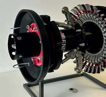
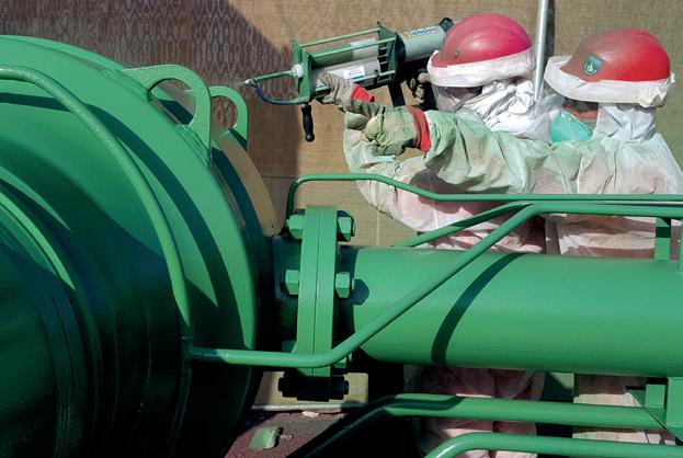
IMU Mapping, when combined with our inline inspection tools, is designed to get you accurate results ensuring your pipeline integrity with confidence. Whether it is measuring bending strain or locating anomalies, you can trust our Data Analysis team backed by over 75 years of experience.

03. Editor's comment
05. Pipeline news
Contract news and updates on PHMSA grants, hydrogen projects and pipelines to support bp's new deepwater US Gulf of Mexico development.
KEYNOTE: SOUTH AMERICA REPORT
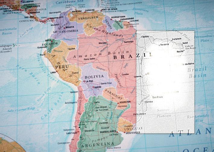
08. Struggles and successes in South America
World Pipelines’ Contributing Editor, Gordon Cope, explores South America’s complex mix of attitudes to the midstream sector.
13. Supercali-thermoplastic
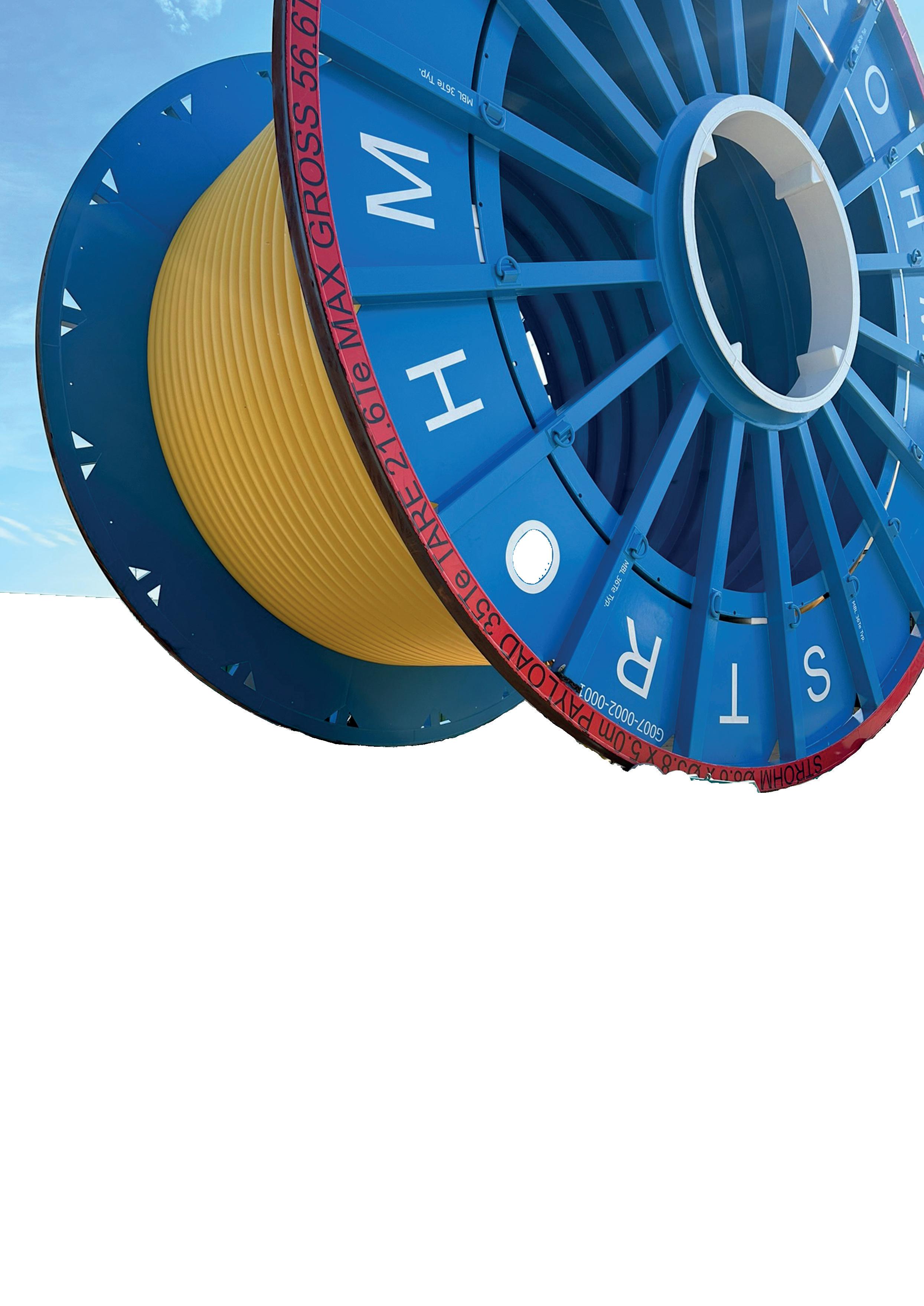
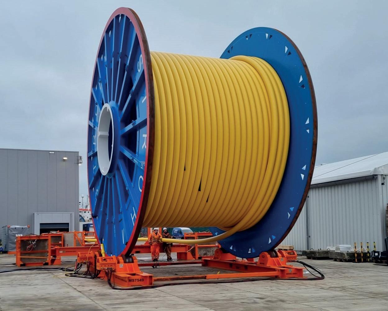
Martin van Onna, co-founder and CEO, Strohm, Netherlands, reflects on a recent breakthrough in the adoption of thermoplastic composite pipe (TCP) offshore Brazil, and what it means for the energy transition at large.
MONITORING
17. Riser and shine
Victor Farid, Baker Hughes.
COVER STORY
20. Demystifying decouplers
Tony Castillo, Dairyland Electrical Industries, USA.



COATINGS REPAIR AND REHABILITATION
27. Catching up with composite repair Matthew Green, Director of Technical Service, CSNRI.
WELDING Q&A
33. With Weldfit and Fronius International GmbH.
INTEGRITY AND INSPECTION
37. Applying technology to the black art of pigging Simon Bell, iNPIPE PRODUCTS.
LEAK DETECTION
41. Choosing the direct or indirect path
Jeremy Silber, Eric Yang, Christopher Lepore and Yash Yadav, Delta Energy Group, USA.

PIPELINE SERVICES
45. Handling the EACOP project Kaikai Shu, ACIMEX, China.














PIPELINE MATERIALS









49. Toppling integrity: the domino effect of inaccurate material verification Dr James Dean, CEO, Plastometrex.
53. Prepping pipes for the future Minchan Jung, Materials Engineer, SeAH, South Korea.



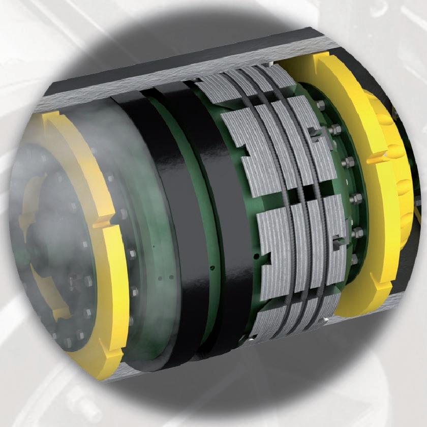
Dairyland decouplers are critical to cathodic protection systems – keeping workers and valuable assets safe from AC faults, lightning, and induced AC voltage – all while optimizing your






















































MANAGING EDITOR
James Little
james.little@palladianpublications.com
ASSISTANT EDITOR
Isabel Stagg isabel.stagg@palladianpublications.com
EDITORIAL ASSISTANT
Alfred Hamer alfred.hamer@palladianpublications.com
SALES DIRECTOR
Rod Hardy rod.hardy@palladianpublications.com
SALES MANAGER
Chris Lethbridge chris.lethbridge@palladianpublications.com
SALES EXECUTIVE
Daniel Farr daniel.farr@palladianpublications.com
PRODUCTION DESIGNER
Amy Babington amy.babington@palladianpublications.com
HEAD OF EVENTS
Louise Cameron louise.cameron@palladianpublications.com
DIGITAL EVENTS COORDINATOR
Merili Jurivete merili.jurivete@palladianpublications.com
DIGITAL CONTENT COORDINATOR
Kristian Ilasko kristian.ilasko@palladianpublications.com
JUNIOR VIDEO ASSISTANT
Amélie Meury-Cashman amelie.meury-cashman@palladianpublications.com
DIGITAL ADMINISTRATOR
Nicole Harman-Smith nicole.harman-smith@palladianpublications.com
ADMINISTRATION MANAGER
Laura White laura.white@palladianpublications.com
Palladian Publications Ltd, 15 South Street, Farnham, Surrey, GU9 7QU, UK
Tel: +44 (0) 1252 718 999
Website: www.worldpipelines.com
Email: enquiries@worldpipelines.com
Annual subscription £60 UK including postage/£75 overseas (postage airmail). Special two year discounted rate: £96 UK including postage/£120 overseas (postage airmail). Claims for non receipt of issues must be made within three months of publication of the issue or they will not be honoured without charge.
Applicable only to USA & Canada: World Pipelines (ISSN No: 1472-7390, USPS No: 020-988) is published monthly by Palladian Publications Ltd, GBR and distributed in the USA by Asendia USA, 701C Ashland Avenue, Folcroft, PA 19032. Periodicals postage paid at Philadelphia, PA & additional mailing offices. POSTMASTER: send address changes to World Pipelines, 701C Ashland Avenue, Folcroft, PA 19032.

The International Energy Agency (IEA) announced in October that the world oil market is expected to experience a significant surplus in the coming year. This statement comes as oil prices have recently increased, due to concerns about potential Israeli retaliation against Iran for a missile attack, which could affect Iranian oil facilities. However, the IEA reassured markets that it is prepared to respond to any supply disruptions, noting that public oil stocks exceed 1.2 billion bbls and OPEC+ spare capacity is at historic highs.
The IEA also revised down its global oil demand growth forecast for this year, largely due to weakness in China. Chinese demand is now expected to grow by 150 000 bpd in 2024, down 30 000 bpd from the previous forecast.
Another forecast released in October was DNV’s Energy Transition Outlook. It projected that 2024 will be the year of peak energy emissions, marking the beginning of a long-term decline in energy-related emissions for the first time since the industrial revolution. Emissions are expected to nearly halve by 2050; however, this reduction falls short of the targets set by the Paris Agreement, with global temperatures projected to rise by 2.2˚C by the century’s end.
The decline in emissions is largely attributed to significantly lower costs of solar energy and batteries, which are driving the phase-out of coal from the energy mix, and stunting oil growth. Annual solar installations increased by 80% last year, while battery costs dropped by 14%, facilitating the 24 hour delivery of solar power and the rise of electric vehicles (EVs), which saw a 50% increase in sales. Notably, China led the global decarbonisation efforts, accounting for 58% of global solar installations and 63% of new EV purchases last year, although it remains the largest coal consumer and CO2 emitter.
While the adoption of solar and batteries has accelerated the energy transition, progress in hard-to-abate sectors remains slow. DNV has reduced its long-term hydrogen forecast by 20% and, despite an increase in carbon capture and storage (CCS) projections, DNV has revised its CCS forecast, predicting that only 2% of global emissions will be captured by CCS in 2040 and 6% in 2050.
So: surplus oil, reduced growth in global oil demand, and the year of peak energy emissions? Within this picture lies many challenges for the oil and gas pipeline sector, not least the imperative to build hydrogen infrastructure.
Sverre Alvik, Director of the Energy Transition Research Programme at DNV, writes in Forbes: “Hydrogen and hydrogen derivatives are needed to decarbonise sectors which are hard to electrify, such as deepsea shipping and aviation. When we last year modelled a pathway to reaching net zero by 2050, we found that hydrogen would need to meet about 14% of the world’s energy needs by the middle of the century. In this year’s Outlook, we forecast that number to be just 4%.1
Alvik argues that there is a growing mismatch between what is required to accelerate the energy transition and the priorities of governments. He says that 4% is still a significant number – equating to trillions of dollars in capital expenditures in hydrogen production and billions of dollars in pipeline construction – but this is only a small percentage of what is required. As it stands, the markets and regulatory framework is just not conducive to scaling hydrogen. Turn to p.53 for more on the development of high-pressure hydrogen pipelines.
1. https://www.forbes.com/sites/sverrealvik/2024/10/08/we-have-reached-peak-energy-emissions-but-we-should-not-celebrate/

Biden-Harris administration announces nearly US$200 million to replace ageing gas pipes
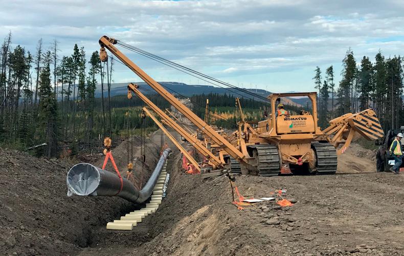
The US Department of Transportation’s Pipeline and Hazardous Materials Safety Administration (PHMSA) announced US$196 million in grants, funded by the Biden-Harris administration’s Bipartisan Infrastructure Law, to repair and replace ageing natural gas pipes. In total, this round of funding will support 60 modernisation projects for natural gas pipelines across 20 states.
“Ageing, leak-prone natural gas pipes can be dangerous, drive
up energy costs for families, and harm the environment, which is why the Biden-Harris administration is supporting funds to replace ageing pipelines,” said US Transportation Secretary Pete Buttigieg. “Through the Bipartisan Infrastructure Law, we’re helping communities across the country carry out projects that will keep people safe while bringing down energy costs for hundreds of thousands of Americans.”
hydrogen and GRTgaz call for cross-border hydrogen pipeline between France and Belgium
The French and Belgian energy infrastructure companies, GRTgaz and Fluxys hydrogen (a subsidiary of Fluxys Belgium) have announced the launch of a market call to assess the needs and economic interest for the creation of an ‘open access’ hydrogen transport infrastructure between France and Belgium. This 150 km network would aim to connect the industrial port area of Dunkirk to the industrial zones of Ghent and Antwerp. The call for expressions of interest will be open from 16 October to 29 November, 2024.
In a press release, Fluxys said that the creation of a hydrogen transport network by pipelines connecting three major industrial ports of the North Sea (Dunkirk, Ghent, and Antwerp) would mark an important step in the structuring of a hydrogen transport network in Northwestern Europe. These large industrial port areas, characterised by the presence of heavy industries such as steel, refining, and chemicals, face significant decarbonisation challenges and are developing numerous projects for green and decarbonised hydrogen.
The first projects for local hydrogen transport networks in these clusters are under study for progressive commissioning by 2030. On the French side, GRTgaz is developing the DHUNE network at the Port of Dunkirk. On the Belgian side, Fluxys
hydrogen is moving forward to complete the first infrastructures by 2026.
GRTgaz and Fluxys hydrogen are now proposing a shared cross-border infrastructure of 150 km that will ensure connectivity between these three major industrial hubs.
Sandrine Meunier, CEO of GRTgaz: “We are proud of this collaboration with our long-standing partner Fluxys. Together, we are convinced that the future of renewable and low-carbon hydrogen relies on the availability of infrastructures capable of transporting and storing large quantities of hydrogen, connecting production sites to consumption areas, both nationally and across Europe. This initiative is fully in line with our vision of building a European hydrogen market and contributing to the decarbonisation of our economy.”
Pascal De Buck, CEO and Managing Director of Fluxys: “Fluxys intends to develop the necessary hydrogen infrastructure so that it is available when the industry needs it. This new collaboration with GRTgaz, a trusted partner of Fluxys for many years, aims to create a cross-border network between Belgium and France and is fully in line with our global approach to contributing to the construction of key infrastructure for the decarbonisation of Northwestern Europe.”
Enbridge Inc. has announced that it will build, own, and operate crude oil and natural gas pipelines in the US Gulf of Mexico for the recently sanctioned Kaskida development, operated by BP Exploration & Production Company.
The crude oil pipeline, named the Canyon Oil Pipeline System, will be a combination of 24 in. and 26 in. pipe with capacity of 200 000 bpd. It will originate in the Keathley Canyon area and deliver crude to the existing Green Canyon 19 platform, operated by Shell Pipeline Company LP for ultimate delivery to the Louisiana market.
The natural gas pipeline, named the Canyon Gathering System, will be a 12 in. pipeline with capacity of 125 million ft3/d and will connect subsea to Enbridge’s existing Magnolia Gas Gathering Pipeline, which then delivers to Enbridge’s downstream FERC-regulated Garden Banks Gas Pipeline.
The agreements contain options which bp may elect to exercise in order to connect potential future production from its emerging Paleogene portfolio into the newly developed
pipelines. Both the Canyon Oil and the Canyon Gas pipelines are being designed to accommodate connections from nearby discoveries.
Detailed design and procurement activities will commence in early 2025 with the pipelines expected to be operational by 2029. The cost of the pipelines will be approximately US$700 million.
“We are extremely pleased to extend an existing relationship with bp and support their new deepwater development. This opportunity diversifies our Gulf of Mexico offshore business, strengthens our significant natural gas pipeline portfolio, and enhances our ability to meet the strategic needs of our customers,” said Cynthia Hansen, EVP & President Gas Transmission and Midstream. “The Canyon Oil and Gas pipelines offer an attractive opportunity for Enbridge to serve customers in the Gulf of Mexico and further expand our US Gulf Coast footprint. The agreements generate stable and predictable cash flow and provide future growth opportunities.”
4 - 7 November 2024
ADIPEC 2024
Vallourec and ASMO sign a strategic partnership
Abu Dhabi, UAE www.adipec.com/visit/registration
20 November 2024
Global Hydrogen Conference 2024 ONLINE www.accelevents.com/e/ghc2024
27 - 31 January 2025
Pipeline Pigging & Integrity Management Conference (PPIM) 2025
Houston, USA
https://ppimconference.com/
5 - 9 February 2025
77th Annual PLCA Convention 2025 Florida, USA
https://www.plca.org/annual-convention-events
11 - 13 February 2025
AMI Pipeline Coating 2025
Vienna, Austria
https://www.ami-events.com/event/c52c6186cbe4-4db1-b7bf-35e6f2e28614
6 - 10 April 2025
AMPP 2025 Nashville, USA
https://ace.ampp.org/home
5 - 8 May 2025
20th Pipeline Technology Conference
Berlin, Germany
https://www.pipeline-conference.com/
5 - 8 May 2025
Offshore Technology Conference 2025
Houston, USA
https://2025.otcnet.org/
19 -23 May 2025
29th World Gas Conference (WGC2025)
Beijing, China
https://www.wgc2025.com/eng/home
Vallourec has announced the signing of a MoU with Advanced Supply Management Operations (ASMO), a joint venture between DHL and Aramco (through the Saudi Aramco Development Company).
ASMO is the first-of-its-kind procurement and supply chain services hub in Saudi Arabia, serving the energy, chemical, and industrial sectors across the MENA region. ASMO will deliver a comprehensive range of end-to-end supply chain services, including sourcing, procurement, inventory management, logistics, warehousing, and a Business-to-Business e-marketplace. Focused on leveraging cuttingedge technology and driving digitalisation, ASMO aims to transform supply chain management operations and create value for companies across the region. Being over the first companies to sign such an MoU with ASMO demonstrates that Vallourec is
Subsea7 awarded contract in the US Gulf of Mexico
Subsea7 has announced the award of a contract between US$50 million and US$150 million for a subsea tieback development in the US Gulf of Mexico.
Subsea7 will be responsible for transporting and installing the flowline, umbilical, and associated subsea components for the tieback. Project management and engineering work will begin immediately at Subsea7’s office in Houston, Texas, and offshore activity is expected to start in 2025.
Craig Broussard, Vice President for Subsea7 Gulf of Mexico, said: “Our strategy of early engagement and close collaboration with clients allows us to approach projects with an open mind and a deep understanding of client needs. This helps us explore innovative, cost-effective ways to deliver optimised energy solutions.”
Taroom Gas Infrastructure MoU signed with AGIG
Elixir Energy Limited has announced the execution of a non-binding Memorandum of Understanding (MoU) with AGI Development Group Pty Ltd, a part of the Australian Gas Infrastructure Group (AGIG).
The MoU provides the parties with an initial framework under which to investigate the potential development of gas infrastructure assets to support the possible future production of gas from Elixir’s Grandis Gas Project in the Taroom Trough.
identified as a key partner in the oil and gas industry in Saudi. It also positions Vallourec at the forefront of a new leading supply chain service provider that will create value for companies in the energy, chemical, and industrial sectors in the MENA region.
Laurent Dubedout, Senior Vice President of OCTG, Services and Accessories and Executive Committee member at Vallourec, declared: “Vallourec is honoured to be selected among the very first partners of ASMO. This testifies to the trust and reliability of Vallourec in Saudi Arabia and aligns with Vallourec’s ambition toward the digitalisation of pipe supply chain management. This is an important milestone to reinforce our presence in the region.”
The signing was held in Dammam in the presence of Salem Al Huraish, ASMO Chairman of the Board, and Craig Roberts, CEO of ASMO.
• IMCA Global Summit 2024: marine contracting industry set for first global gathering since 2018
• CNRL takes PetroChina’s space on Trans Mountain pipeline
• CRC Evans completes successful multi-million campaign offshore Nigeria
• SLB announces agreement to sell its interests in Palliser Block
• NDT Global partners with Aramco to launch 56 in. ultrasonic inspection tool
Follow us on LinkedIn to read more about the articles linkedin.com/showcase/worldpipelines

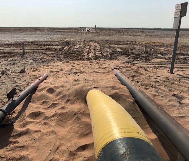
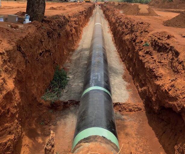
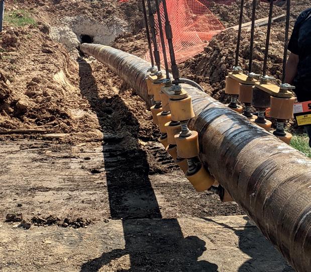


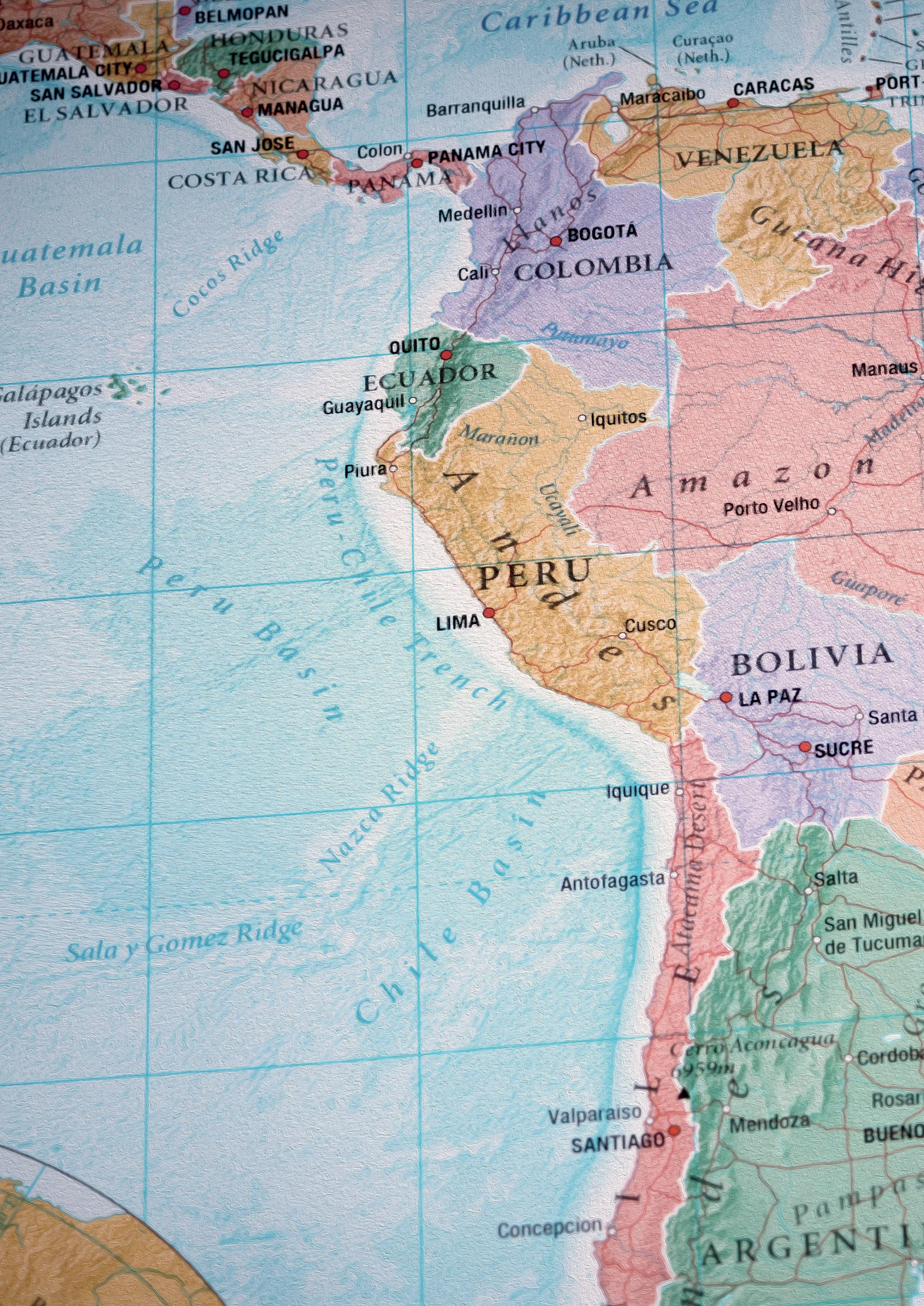
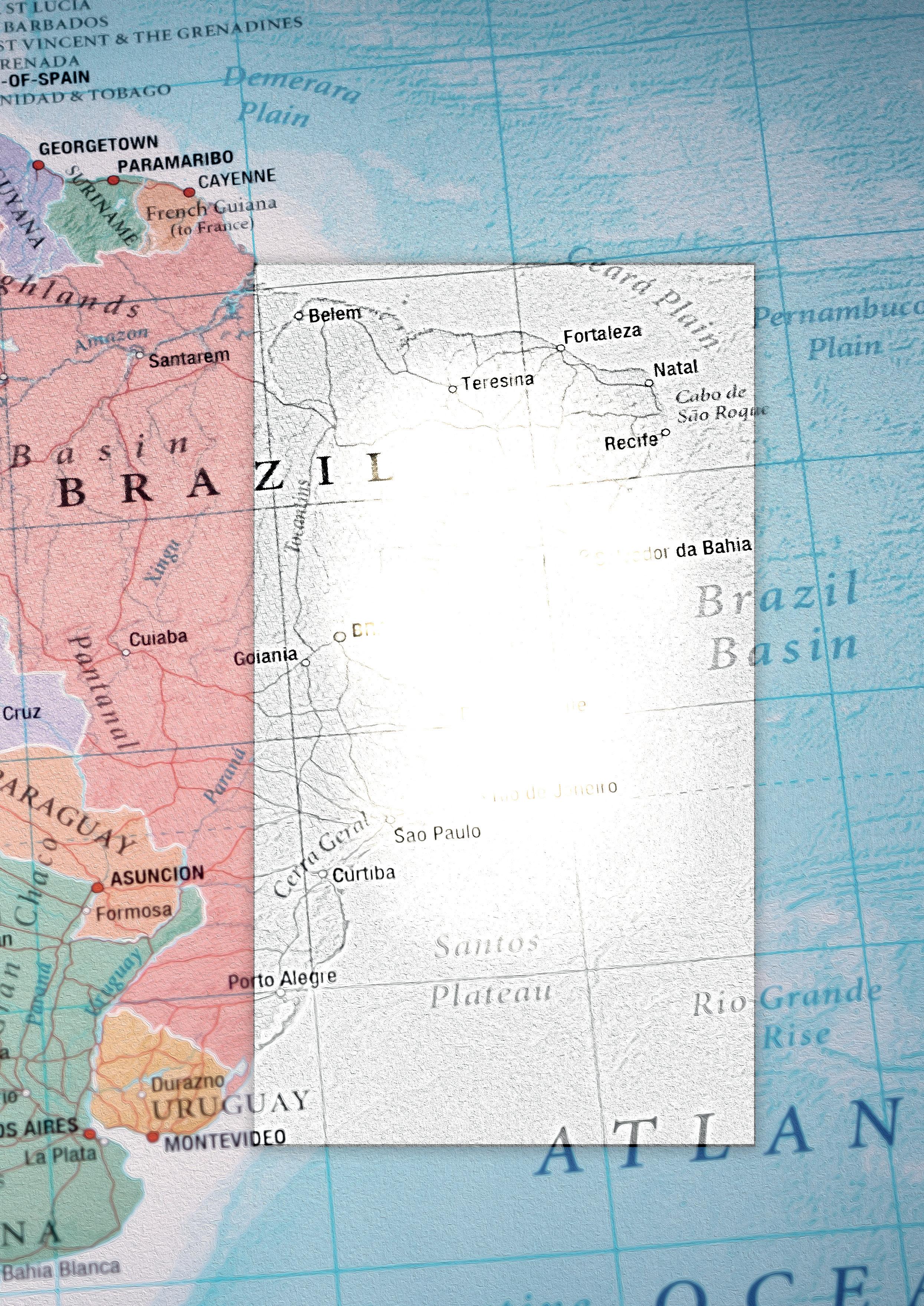
outh America is home to jurisdictions that hold the world’s largest crude reserves, the fastest growing oil exports, and a rapidly expanding population eager to consume energy. It also contains a wide assortment of regimes, from autocrats to pro-business democracies, a range that profoundly affects how its oil and gas assets are developed.
In the last decade, Guyana has risen to become one of the continent’s largest oil exporters. Currently, a consortium led by ExxonMobil produces approximately 650 000 bpd; in August 2024, ExxonMobil announced that it is proceeding with Hammerhead, its seventh offshore oil project in the Stabroek block. When it is commissioned in 2029, the FPSO will produce up to 180 000 bpd, boosting the country’s production to 1.4 million bpd.
In addition to crude, a significant amount of associated natural gas is produced. Most is currently reinjected to maintain reservoir pressure, but Guyana currently imports heavy oil to generate electricity at great cost and would like to commercialise the gas to lower rates and reduce power blackouts. The government has negotiated an agreement with ExxonMobil to deliver gas from the Liza project onshore where it can power turbines. The Gas-to-Energy project consists of two main investments; a 225 km offshore pipeline costing approximately US$1 billion and a 300 MW electricity complex near the capital of Georgetown, estimated to cost US$759 million. Construction of the pipeline is nearing completion, with connection to the offshore platform expected by the end of 2024. The electricity complex is on schedule to be completed by the end of 2025. In addition to electricity, the government is exploring further revenue streams related to natural gas, including the sale of NGLs.
Although Mexico has significant fossil fuel reserves, it relies heavily on cheap shale gas from Texas. Over the last decade, several thousand kilometres of gas mainlines have been built, primarily to deliver supplies to state-owned utility CFE. Current import capacity exceeds 13 billion ft3/d.
Mexican consumption stands at 9.4 billion ft3/d, leaving ample opportunity for new gas-powered projects. Two new LNG plants are being built along the Pacific coast. Sempra Energy’s Energía Costa Azul (ECA) LNG, located in Baja California, is a former LNG import site. The 3 million tpy train is expected to be commissioned by 2025, and could ultimately be expanded to 12 million tpy. The Mexico Pacific Limited (MPL) LNG project is located on the Sea of Cortez. The latest plan is to build three trains totalling 14.1 million tpy capacity in Phase 1, and a further three trains in Phase 2, doubling capacity to 28.2 million tpy. Both ECA and MPL are already served by major pipelines, including the 670 million ft3/d Topolobampo line.
The 340 000 bpd Dos Bocas project in the state of Tabasco is the first Greenfield refinery to be built in Mexico in several decades. In order to service the US$18 billion refinery and utilities in southern Mexico, TC Energy and CFE are building the 1.3 billion ft3/d Southeast Gateway Pipeline. The US$4.5 billion line will connect to the Sur de Texas pipeline in Veracruz and run 770 km offshore to Tabasco. In May 2024, TC Energy reported that 70% of the line has been completed, and that the project is expected to come online in mid-2025, and within its budget.
In July 2024, France-based Engie and Australia’s Macquarie Asset Management announced they were jointly expanding the Mayakan natural gas system, located in the Yucatan Peninsula. The US$3 billion project will see the construction of a 700 km gas pipeline, doubling current capacity through the states of Chiapas, Tabasco, Campeche and Yucatan. CFE will be the primary customer.
Shifting political winds remains the major complication regarding investing in Mexico. Since President Pena Nieto eliminated Mexico’s state monopoly in the oil and gas sector a decade ago, international investors have been whip-sawed, first into investing billions into exploration and development, then through a series of nationalistic retrenchments as subsequent President Andre Manuel Lopez Obrador (AMLO) championed state-owned Pemex.
The election of AMLO’s chosen successor Claudia Sheinbaum in 2024 has left analysts unable to determine if the new administration will stick with prioritising Pemex or seek out accommodation with private investors to reverse chronic sector underinvestment that has seen production plunge from 3.4 million bpd two decades ago to current levels of 1.5 million bpd.
So far, reviews are mixed. The new administration has signaled a desire to encourage investment in renewables, but with stateowned electric utility CFE taking a leading role. Likewise, federal regulators have been examining new farm-outs along the lines of Trion deepwater field, a JV between operator Woodside Energy and Pemex, but are still expected to heavily favour the latter as a state-champion.
For many decades, Bolivia exported natural gas via the 557 km Gasoducto Argentina (Yabog pipeline) to Argentina and the 472 km Gasoducto Bolivia-Brazil (GASBOL pipeline) to Brazil. But declining reserves and insufficient investment in exploration led to a decrease
in gas production from 20 billion m3/y in 2013 to 9 billion m3/y in 2023; exports were forecast to discontinue in 2029. Now, a new discovery is expected to create a resurgence in the country’s beleaguered oil and gas sector. In July 2024, state-owned YPFB announced that it had discovered the Mayaya Centro prospect containing approximately 1.7 trillion ft3 of non-associated gas. Along with the 2023 discovery of Remanso-X1 in the sub-Andean thrust and fold belt, the new reserves will allow Bolivia to stem the decline in production and increase exports. YPFB has announced a plan to place the fields into production in three years, but analysts caution that the remoteness of the discoveries and the lack of infrastructure makes the prediction optimistic. In the meantime, producers of shale gas in Argentina are exploring ways to reverse Bolivia’s pipeline network to deliver gas to Brazil.
Colombia is South America’s third largest oil producer, with an output of approximately 780 000 bpd (and 1 billion ft3/d of associated gas). It has only eight years of crude and gas reserves left before it runs out, however, and the current regime has little enthusiasm for fossil fuels. In June 2024, left-wing president Gustavo Petro banned awarding new hydrocarbon exploration contracts. In addition to a prohibition on fracking and tax hikes, analysts place grave concerns on the future of the sector; private investment has dropped by 30% y/y.
In August 2024, Ecopetrol once again temporarily suspended operations on the Cano Limon-Covenas pipeline due to five bombing attacks. The 210 000 bpd line runs adjacent to the Venezuelan border, in a region in which the guerrillas of the National Liberation Army operate. The attacks, which have been occurring roughly twice a month, cause environmental damage due to spillage. Narco groups also frequently drill into the pipeline to steal crude; makeshift refineries then distill a primitive form of gasoline for use in cocaine cultivation. The country’s second major pipeline, the 85 000 bpd Trasandino line, which runs from Putumayo province to the Pacific coastal city of Tumaco, was shut down in December 2023 when thefts ballooned to 3000 bpd. Ecopetrol forecasts Transandino will remain offline until the end of 2024.
Argentina’s Vaca Muerta unconventional shale contains an estimated 16 billion bbl of oil and over 300 trillion ft3 of gas. Production has risen to 300 000 bpd and 2 billion ft3/d from virtually nothing a decade ago. But the play has the potential to surge to 1 million bpd and 5 billion ft3/d by 2030; the main bottlenecks are takeaway capacity and regulatory policy.
In terms of takeaway capacity, the pipeline network in Neuquén province is undergoing significant expansion. The first stage of the 1000 km Nestor Kirchner gas pipeline entered service in mid-2023, adding approximately 800 million ft3/d, with a second phase of approximately 500 million ft3/d underway. Total costs are estimated at US$3.4 billion. New projects will be needed by the end of the decade to meet forecast growth in gas production.
In May, 2024, state-owned YPF began construction of the first phase of the Vaca Muerta Sur crude pipeline. The 600 km line is designed to move unconventional crude from Neuquén province to an export terminal in Punta Colorada in the Rio























Negro province. The first phase is a 130 km new-build that will connect Vaca Muerta oilfields to the existing Oldelval network. Once completed, the pipeline will allow for transport of 390 000 bpd, doubling current pipeline capacity in the basin. In the meantime, mono-buoys and tankage are being built in Punta Colorada terminal to allow VLCCs to dock. Once completed, the US$2.5 billion Vaca Muerta Sur network will allow the export of 135 million bbls/y.
In July 2024, Pan American Energy signed a 20 year agreement with Golar LNG to dock a FLNG vessel in the Atlantic port of Bahia Blanca. The project will allow Argentina to export part of the estimated 307 trillion ft3 of gas found in the Vaca Muerta shale deposit. Exports are expected to begin in 2027.
Argentina’s YPF and Malaysia’s Petronas also have ambitious plans to build a proposed 5 million tpy LNG plant. In August 2024, they announced that the plant would be built in the Patagonian province of Rio Negro, not Bahia Blanca as originally proposed, in order to take advantage of a shorter pipeline distance and deeper port draft allowing larger vessels. While details of the pipeline have not been released, a 5 million tpy LNG plant would need approximately 650 million ft3/d feed.
On the regulatory front, the administration of President Javier Milei (a free-market economist who assumed office in December 2023), has passed legislation designed to encourage investment in major energy projects. The Basis Law calls for significant tax breaks on investments such as pipelines, as well as exemption from export taxes up to three years. The aim is to create a favourable environment for energy infrastructure investment.
Venezuela continues to stagger from one crisis to another. In July 2024, President Maduro announced he had prevailed in the federal election, with opposition leaders claiming their candidate, Edmundo Gonzalez Urrutia, had won by a wide margin. Amid country-wide demonstrations and arrests, the latter fled to Spain in exile. Maduro is expected to start his third, six year term in 2025.
In the meantime, output in the oil and gas sector continues to under-perform. While crude production has increased from under 600 000 bpd in 2022 to over 800 000 bpd, this is still a far cry from the 3 million bpd two decades ago. State-owned PDVSA is languishing under an immense financial scandal involving the sale of over US$20 billion in oil cargoes to shadowy entities dating back to 2020. In April 2024, Venezuelan authorities arrested former Oil Minister Tareck El Aissami, a staunch ally of President Maduro, on charges of treason, money laundering and misdirection of public funds. Prosecutors say he and confederates used US-imposed sanctions to take direct control of shipments, diverting payments to their own accounts.
The lack of maintenance funds has had a profound impact on the midstream sector. Independent observers reported 86 oil spills in 2023, mostly in the Lake Marcaibo region, the epicentre of Venezuelan oil production. The spills are primarily caused by the deterioration of the 25 000 km of pipelines that lay beneath its waters; they have a devastating impact on the country’s shrimp farmers, one of the few sectors of the economy that still thrive.
With the election of left-wing President Petro, relations between Colombia and Venezuela have vastly improved. In 2023, Petro and Maduro agreed to re-open the 139 mile Antonio
Ricaurte gas pipeline that runs from Venezuela to Colombia. The mothballed, 5 billion m3/y line was originally built in 2007 to supply gas to Venezuela for reinjection into mature crude fields, but eventually reversed to serve Colombian utilities. Analysts see the agreement as largely political, as PDVSA is financially unlikely to rejuvenate its dilapidated portion of the line.
Brazil now produces more than 4.4 million bpd of crude liquids, with significant increases expected over the next 18 months. A new field is projected to come on-stream in late 2024 when the 100 000 bpd FPSO Maria Quiteria arrives at the Jubarte field in the Campos Basin’s pre-salt layer. In addition, three other fields are expected to see new FPSO capacity in 2025; 400 000 bpd at Buzios and 180 000 bpd at MERO4.
Such impressive growth may not continue into the long-term. Since his re-inauguration in January 2023, President Lula de Silva (Lula) has vowed to redirect profits from Petrobras toward the social wellbeing of the nation. Under the previous administration, assets of the state-owned company had been sold to private investors, including gas pipelines Nova Transportadora do Sudeste (NTS) and Transportadora Associada de Gás (TAG) for approximately US$7 billion each. After entering office, Lula vowed pending sales could be scratched, including the Transportadora Brasileira Gasoduto Bolívia-Brasil (TBG), which operates the BoliviaBrazil (Gasbol) pipeline.
New regulations also place greater state control over the sector. A decree from ANP, Brazil’s oil regulator, calls for limits on the amount of natural gas that operators can reinject in offshore fields. Norway’s Equinor is designing its newest offshore field, Raia, to comply with the new regulations. The US$9 billion project will include a pipeline that could supply up to 15% of Brazil’s gas when it comes online in 2028.
Countries in South America are generally not as enthusiastic as other jurisdictions when it comes to low-carbon energy. The exception is the northeastern Brazilian state of Ceará, which has embraced the development of green hydrogen and ammonia in order to monetise its abundant solar and wind power. In June 2024, the state government announced it had reached an agreement with Madrid-based FRV to invest US$5 billion to build the H2 Cumbuco plant in Ceará’s Pecém Industrial and Port Complex. The first phase of the project will have a capacity of 400 000 tpy of ammonia, eventually rising to 1.6 million tpy. The state has also signed five other MOUs with international firms, including BP and Fortescue. The output is primarily destined for European markets.
In conclusion, the ever-evolving governments in Latin America have a profound effect on the continent’s oil and gas sector. The business-friendly administration of President Melei in Argentina boosts the prospects of the Vaca Muerta play, while leftist governments in Brazil and Colombia seek to harness oil and gas revenues for social agendas (fortunately, few countries are on the path of chaos like Venezuela). As for midstream companies seeking opportunities, the growth of inter-state movement of gas as proposed in Argentina and achieved in Mexico will offer enticing prospects for the decade to come.
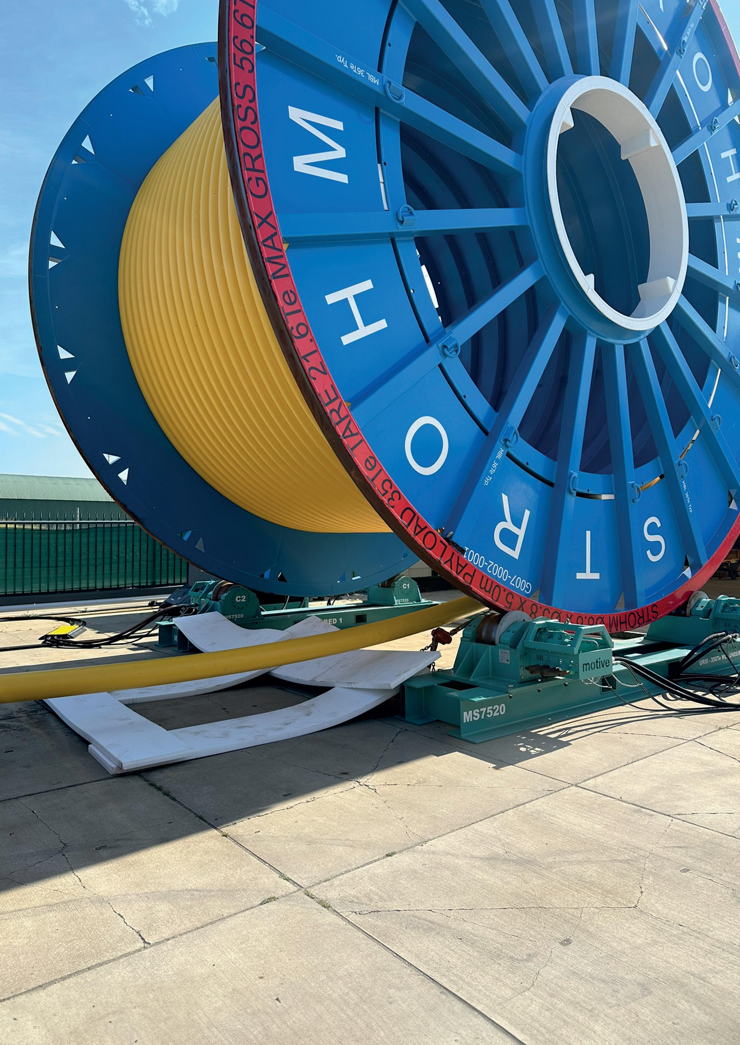
crevice corrosion, intergranular corrosion, erosion corrosion and atmospheric corrosion. In pipelines, some of these forms of corrosion can be dealt with by applying a ‘corrosion allowance’, typically some 3 mm of additional steel thickness, which ensures that product lifetimes are met if the corrosion mechanism remains as predicted during the design phase. Some forms however, such as MIC, pitting corrosion and SCC, cannot be resolved by a conventional corrosion allowance. Throughout the years, there are thousands of corrosion authorities around the world who have researched this area and made it their area of expertise.
In this context, one might think that using materials that do not corrode, such as composite materials, would be a no-brainer. Surely, once proven, everybody around the world working on pipelines, flowlines, risers and jumpers would flock to use this non-corroding material. There would be one ‘breakthrough’, that of proving and achieving technology readiness, after which acceptance would be global instantly, given the challenges and leakages caused by corrosion, especially if there is a proven track record and an attractive business case.
Alas, there is no such thing as a breakthrough. When a novel technology disrupts existing entrenched interests and business models, renders existing knowledge redundant, and requires standards to be revised or new ones created, then formidable barriers to entry are created that continue to exist for a long time.
At Strohm, what does this mean for us as a disruptor? It means that we cannot relax and sit back. There is no ‘Hoover Dam project’ that will flood the company with revenue. Once the technology is accepted, piloted and a track record begins to grow through working with the leaders in the field, a disruptor needs to push harder to create the acceleration that will truly make the technology broadly accepted and cements its position. In a conservative industry, this requires: ) Knowledge sharing and teaching.
) Aligning the proposition with the drivers of the end users.
) Enabling the advisors and supply chain to support, shine, and take part in the success.
Here, we describe the above three elements and how Strohm implemented these to become successful in the market. As Strohm develops and manufactures TCP, we start with knowledge sharing.
Carbon fibre-based composites do not suffer from fatigue. This means that we can apply as many load cycles as we want; the fatigue life simply is not a critical parameter in the design, and we only need to consider the static loads. As simple as this may sound, in our design and qualification approach we prove it every single time, and we need to convince our clients of what this simplicity means.
While fatigue is not a consideration in most composite structures, other long-term loads such as creep and ageing, can be. These, together with the single and combined load cases, need to be fully understood and finite element analysis is a good tool to assess this. To build a proper FEA model however, one requires material data, both around strength (resistance) and stiffness – this is where things get trickier. Where steel has a pretty stable stiffness, the stiffness of a thermoplastic composite is influenced by temperature and by the fluids being transported. This is the key element in our knowledge sharing with engineering houses, installation contractors and end users alike; how to build a design and be confident that it will be able to support all single and combined load cases.
Where other flexible pipe manufacturers hold their knowledge close to their chest, we turn it around and we share as much as realistically possible. We share how we model the influence of temperature, and that of fluid, how we assess rapid gas decompression, and chemical resistance, how we consider solubility parameters in assessing the level of swelling of the material, and how we can translate this into a simple shift in temperature.
To create and accelerate acceptance, you have to build trust by being transparent. At Strohm we share our knowledge and enable others to fully understand our product. In doing this, we provide support for our partners such as engineering houses to perform linear analysis using regularly available finite element analysis (FEA) tools. We provide models that allow them to do a thorough analysis. It is only if that is not providing an accurate result that we will consider non-linear analysis which we can do in house.
At Strohm, through the years we have seen multiple cases where engineers did not have sufficient time (hours or budget) to assess TCP as an alternative to steel or flexible pipe. As such they advised the operator that “TCP would probably not work”, as of course it would be difficult to say, “I don’t know, and I didn’t have time to call Strohm”. While frustrating, we have acknowledged that this is a reality we cannot ignore. Therefore, while providing knowledge and educating the industry (as above), we also need to ensure that a maximum technology
pull is created by the end user. This makes sense because, ultimately, it is the end user that benefits most from something that simply does not corrode or fatigue. We need to ensure that the end user demands a proper assessment of this novel technology in comparison to the pipes that it is accustomed to using (and which are known to corrode). So, we ensured that we always have a perfect alignment with the drivers of the end user:
) We created business cases on each product which wins from competition on a total installed cost basis – CAPEX.
) The fact that the product does not corrode, fatigue or embrittle, reduces OPEX to a bare minimum, making the TOTEX case even stronger.
) We provide a full lifecycle solution for infield inspection for our partners.
) We provide best-in-class warranty conditions.
Enabling the supply chain to support, realise and share success
The final part is enabling all parties involved in providing engineering design services or engineering advice, those who sit on committees, those who install pipes and who provide inspection and repair services over the life of the field, to share in the success.
For engineers we have implemented a tool to aid them in their design efforts. We developed a web-based tool, enabling users to design a TCP using their own input parameters, and creating datasheets with all relevant information using these. In future, the tool will also export full FEA models allowing for more detailed assessments, such as Orcaflex. We provided in-depth design training and guidelines to enable engineering houses to perform their own independent verification.
For installation contractors our approach was different. When an installation contractor has a record backlog, with vessels scheduled to work around the clock for years to come, there is no incentive for them to consider something that, in their mind, on their assets and for their engineers, is new. To resolve this, we therefore needed to show the enabling features for them. What if our product reduces their risk instead of increasing it? What if our product provides a level of flexibility to their operations that other products can’t? What if our product provides flexibility in terms of vessel choice? Suddenly something that is “new, unknown and a risk” becomes a huge opportunity. This is what Strohm did. We developed a completely new product line, called Jumper on Demand, that was totally new in the marketplace. It provides local content, maximum flexibility and lower total installed cost. Further, we developed installation methods, allowing TCP to be installed using smaller vessels and rental equipment.
Conclusion
So, what do we learn from this when looking at the future, and more specifically, when we consider the energy transition? We see that hydrogen and carbon capture and storage are two major building blocks of the energy transition, at least where
the transfer of fluids (and gases) is concerned. If we follow the same approach of sharing knowledge aligning with the drivers of the end users and helping the supply chain win, we come to the following conclusions that provide insight into our approach:
Knowledge sharing
First, it is stupid to make grand claims that “steel does not work”. Steel has been used for many years in the refining industry, transporting hydrogen. It has also been used for years in pumping (dry) CO2, for instance in The Netherlands, where Strohm is headquartered.
Where embrittlement is a known phenomenon, there are ways to accommodate this, for instance, by increasing the wall thickness thereby, lowering the mean stress levels. We are not trying to discredit steel, rather, we should quietly and consistently continue to explain the fundamental benefits of TCP, especially for certain applications. Lumping hydrogen and CO2 together for this case we arrive at the following:
) Where CO2 includes sulphur oxides, nitrogen oxides and other impurities, it becomes increasingly corrosive, and here a corrosion allowance won’t do the trick. This is where TCP comes in, and its fundamental benefit that it does not corrode.
) Where hydrogen can easily be pumped through steel at stable pressures, it becomes more challenging when you want to use the pipeline infrastructure to store your (green) hydrogen, especially when produced using intermittent energy sources. Here, the fact that TCP does not embrittle, and does not fatigue, makes it a very serious contender.
Here we see an interesting opportunity. Where in conventional energy, steel has been used since day one, this is not the case for hydrogen and CO2 transportation. As these industries emerge, TCP should be considered from the start as its attributes make it the default option, rather than an alternative, to steel.
In the case of hydrogen and CCUS, TCP and steel are at the same starting point when engaging with regulators and independent verification bodies, but TCP can and should advance much quicker due to its qualities. Our track record in conventional oil and gas applications counts, particularly in light of the challenging investment environment for renewables.
And finally, how to make the supply chain win? Here, the risk factor comes in. Contractors know that it is virtually impossible to measure whether an infrastructure is dry enough to receive CO2 and even small amounts of moisture left on a valve can create corrosion. Flexible steel pipes are known to fail due to issues with stress corrosion cracking.
There are still contractors and engineering houses that are willing to take the lead in offering something they know is the best solution. The balance of risk and reward comes out to favour a technology that will propel them into the future of energy: TCP.
he dynamic nature of the oil and gas sector means that the playing field is constantly changing, so energy companies have learned that irrespective of current market conditions, Victor Farid, Baker Hughes, explores how advanced monitoring technology extends flexible riser service life.
the best way to compete is to safely extract as much value as possible from existing assets. As these assets age, however, achieving that objective becomes more challenging. While life extension for floaters is practical and achievable, as ageing assets near the end of their design life, regulatory agencies require more evidence that the units can operate safely. Brazil’s National Agency of Petroleum, Natural Gas and Biofuels (ANP), for example, has exacting requirements for demonstrating older floating production vessels are fit for operations.
With 45 FPSOs, Brazil has more of these units in service than any other area of the world, and in the interest of protecting the environment, the ANP wants concrete evidence that these vessels are sound. Energy technology companies are rising to the challenge, developing tools that enable proactive rather than reactive decision making about repairs and maintenance while simplifying the process of safely extending the field life of production units.
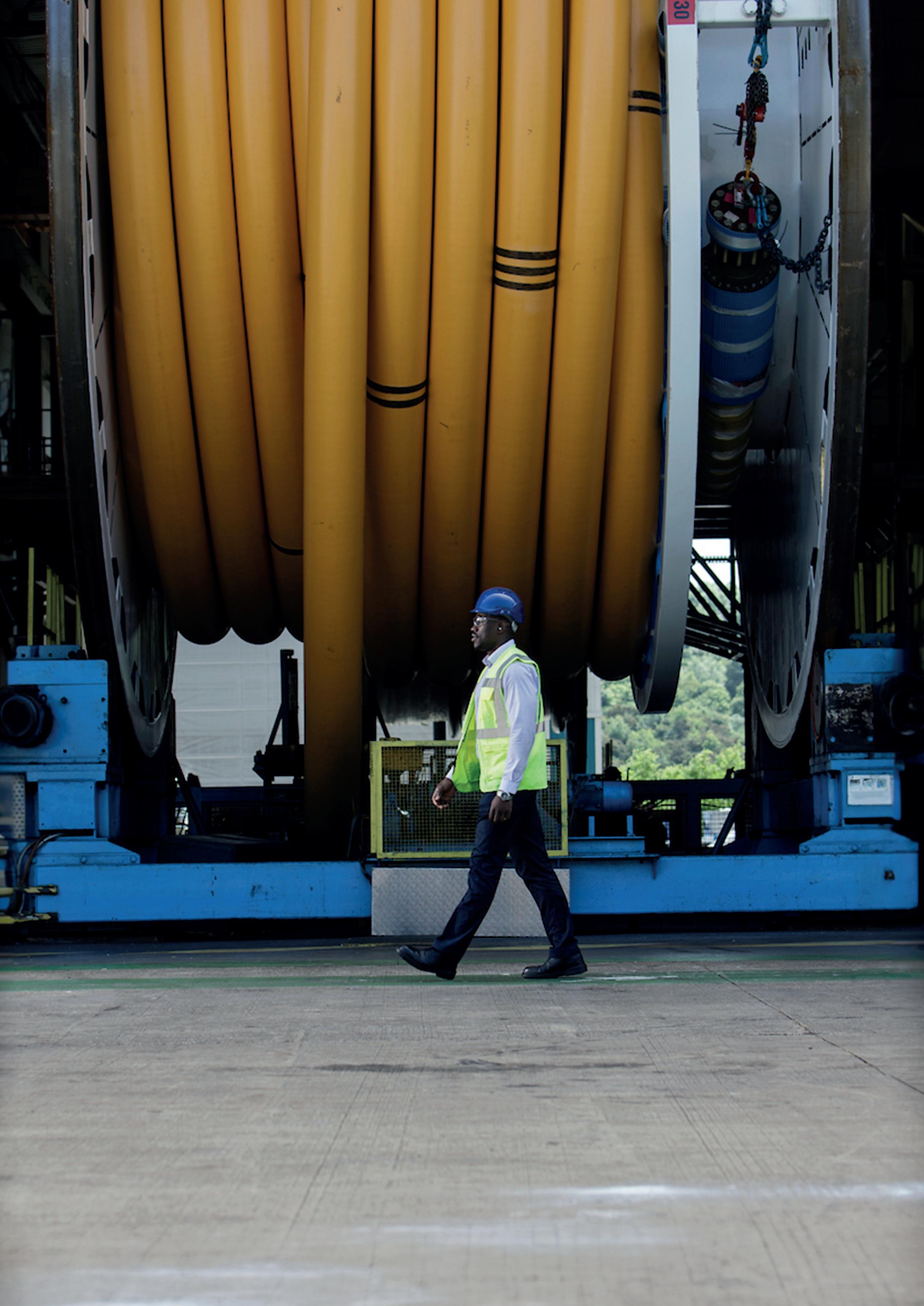
Flexible risers have been developed with reliability at the forefront and only 4% of the installed base is expected to experience some type of damage during its service life. Manufacturers and operators have also developed a keen understanding of the potential points of failure in these systems. However, monitoring the condition of these assets is critical, especially as they age. Because of the length of the risers and the danger of manned underwater diving operations, inspections have relied primarily on visual examinations utilising camera-equipped remote operated vehicles (ROVs). Periodic physical assessments are essential to managing riser health because they capture anomalies on the sheath surrounding the riser, but they have limitations. Although visual inspections can reveal external damage, they are unable to see beyond the surface, so any wear or damage beneath the sheath cannot be monitored.
The entirety of the riser must be assessed to truly understand its condition and predict the likelihood of failure. This requires inspections to take place much more frequently. New technologies are changing the way these inspections are performed, making it possible to capture asset integrity data and evaluate it in real time. As this approach gains ground, the industry is seeing the value in moving away from traditional inspection methods and approaching asset integrity evaluation in a way that is fundamentally different.
Continuous monitoring is at the heart of this approach. With real-time data, owners can identify anomalies as they happen and make informed decisions about the type and extent of repairs needed. Understanding the severity of the damage enables informed decision making. If the damaged riser is a threat to operations, it should be replaced as soon as possible, but if the damage does not prevent the riser from functioning safely and reliably, the weakness can be monitored and managed. Then, when conditions change and it becomes evident that the wear requires attention, action can be scheduled judiciously to avoid both operational disruptions and potential incidents.
When inspections were done periodically, there was no way to know precisely when an integrity issue occurred or how long it had existed. Assumptions had to be made based on when the anomaly was discovered during a scheduled inspection.
Without definitive data to pinpoint when damage occurred, engineers have to rely on conservative assumptions to determine the impact of damage on the remaining service life of the riser. Following this approach helped avoid incidents but often led to risers being taken out of service prematurely.
To maintain safety standards while operating within less conservative parameters, operators need to be able to understand how a riser is performing at any given time and be able to recognise anomalies that do not threaten riser integrity.
The continuous monitoring approach employs multiple technologies for gaining insights into riser health. New tools make it possible not only to determine the external condition of the equipment but also to look beyond what is visible on the surface to understand riser integrity at a structural level.
Access to better data leads to extended service life and better field management decisions. The process begins with acquiring more precise data about the protective covering. Recently-introduced tools for electronic breach detection are replacing traditional visual inspections to identify anomalies in the protective riser sheaths and ascertain their size. This is done by keeping an electrical signal running through the riser, using tensile wires as a conductor. Then a small ROV scans the riser with a special sensor that can capture the signal if there is water in contact with the electrified wire. This identifies if a riser has been flooded and the precise location of the breach.
Another innovative inspection tool has the ability to look beyond the outer sheath of the pipe to examine the tensile wires of the riser – the structural layers responsible for the axial load of the pipe, which are prone to fatigue due to corrosion. This nondestructive testing tool – the industry’s only integrity management tool for assessing the load bearing condition of steel armouring wires – is designed to measure changes in applied stress using an electromagnetic stress management system.
It differs significantly from other inspection methods that require removal of the sheath to assess the armouring wires. Mounted externally at any point along the riser, the tool applies a magnet sensitive to mechanical stress and measures through the sheath to identify unloaded armor wires within +/-15 metres from the mounting location. Once anomalies are identified, the affected riser can be monitored to allow for production continuity while avoiding catastrophic events. Then safety assessments can be made using the design specifications for the riser to determine if the damage compromises performance and integrity.
Asset integrity is also being improved through a process that employs a flexible pipe vent gas monitoring system to perform chemical analysis on permeated annulus gases in real time. Because risers normally are designed for a specific level of H 2S or CO 2, monitoring gas levels is critical, due to the natural tendency of wells to see changes in its gas composition throughout the production life. This multiplexing system can continuously monitor up to eight individual risers to provide valuable information from fields with corrosive gases or from areas susceptible to well souring.
Understanding the true condition of the riser and all its components and being able to monitor anomalies as they progress dramatically improve riser integrity management. With a better understanding of the health of the equipment, it is not only possible to keep a minimally damaged riser in service but also allows an undamaged riser to be kept in production safely beyond its projected design life, increasing an operator’s return on investment.
When a riser’s service life comes to an end, these tools ensure there is a much better understanding of its condition, allowing data to replace assumptions about observed damage.
Because constant monitoring allows potentially serious issues to be identified immediately and addressed swiftly, some regulatory agencies have considered data gathered through these technologies sufficient for approving the continued use of damaged risers in the field.
One of the things that makes continuous monitoring so valuable is that it is not only appropriate for brownfield developments but for greenfield installations as well.
It is not unusual for a riser to sustain damage during installation. Risers can suffer scratches, dents and cracks during transportation and installation, or damage can occur when the riser is struck by debris or an object during deployment. In other instances, hydrostatic pressure can damage a riser that is not properly installed. In many cases, there is no physical indication of a defect, yet any damage sustained during installation can impact service life.
Planning for continuous riser monitoring from installation to decommissioning addresses the full spectrum of asset integrity concerns. Investing in the technology for inspecting risers during installation and continuously monitoring them from that point forward can improve operational safety for the entire service life of the riser and reduce unplanned downtime.
The new technologies that are improving the ability to monitor asset integrity today are the first step on the journey. Soon, additional advances will enable real-time fatigue calculations using existing formulas and specially designed algorithms. In time, it will be possible to improve these models using historical performance data and apply lessons learned to deliver even greater improvements in riser integrity management.







































































































































































Tony Castillo, Dairyland Electrical Industries, USA, outlines the role that decouplers play in ensuring safe and sustainable pipeline operation.





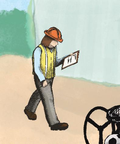

















































































n the world of oil and gas pipelines, decouplers play a critical role enabling safe and sustainable pipeline operation. In fact, decouplers perform an essential role in corrosion mitigation – ensuring safety, regulatory compliance, preventing costly damage and downtime for pipelines and related assets. They also provide shock protection to personnel and pipeline assets from safety hazards, caused by power line faults, electrical failure of equipment, and lightning strikes.
The decoupler, however, is often misunderstood and its application under appreciated. Here we demystify decouplers and explain the vital role they play.
For logistical, land access, and environmental purposes, it is a global norm for pipelines to share rights-of-way


























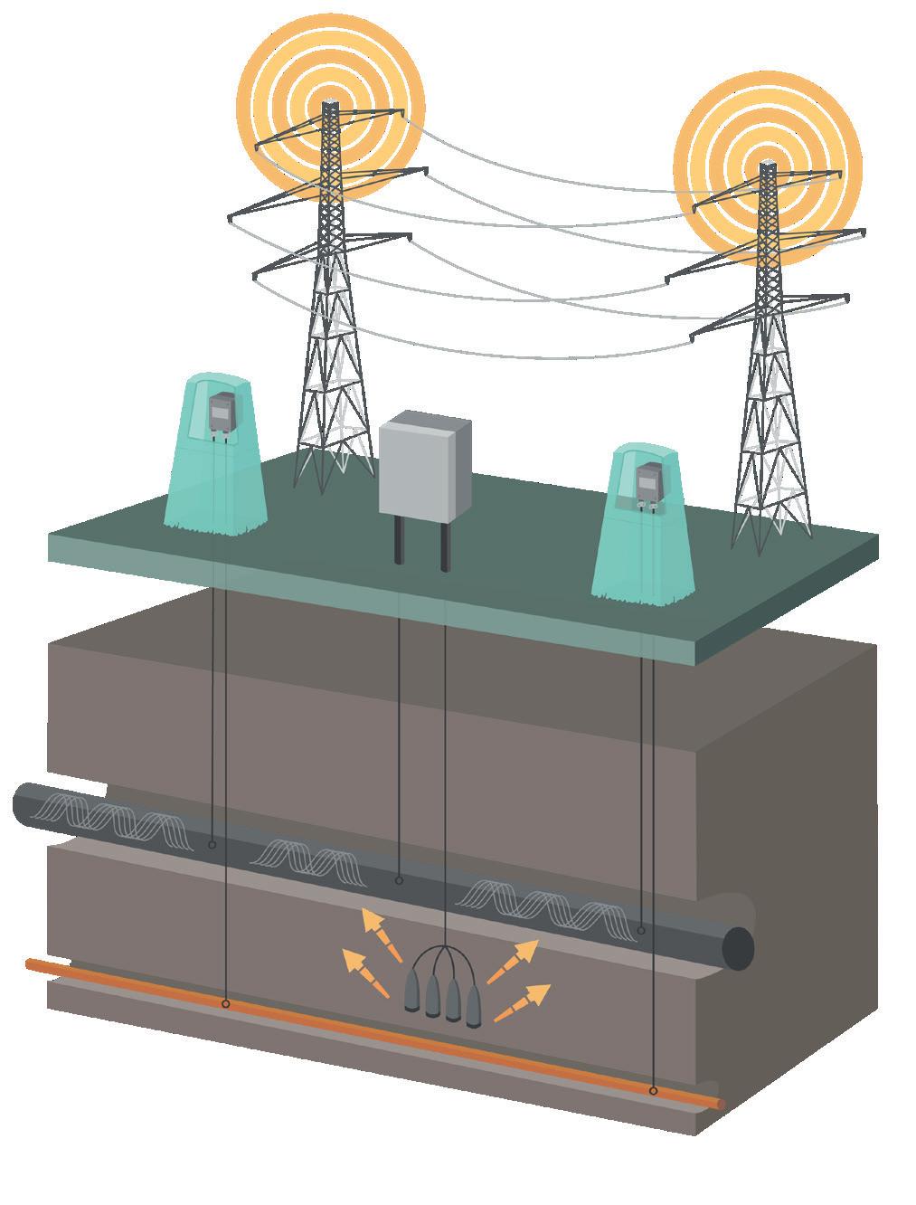
(ROW) with high-voltage power lines creating a network of utility corridors. In these multi-purpose routes that often span long distances, the phenomenon of alternate current (AC) interference risks increase due to undesirable AC influences. This is a frequent problem caused when AC induced by transmission lines creates a magnetic field that generates voltage in buried pipelines. It also increases the shock hazard risk to personnel who come into contact with the pipeline.




To mitigate the risk of galvanic corrosion to underground pipelines and other buried assets, cathodic protection (CP) is commonly used. This is the application of an electrical current to the exposed metal surface of a pipeline, and when properly applied, it is an effective technique to minimise the natural corrosion process that occurs. To maintain effective CP coverage with minimal current demand, the structure must be well-isolated from earth to optimise the CP direct current (DC) flow.
Electrical earthing is required for personnel safety and the protection of the affected structure from damage due to over-voltage conditions. The addition of earthing
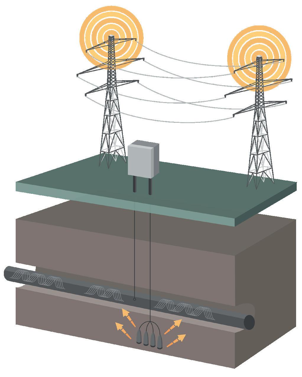
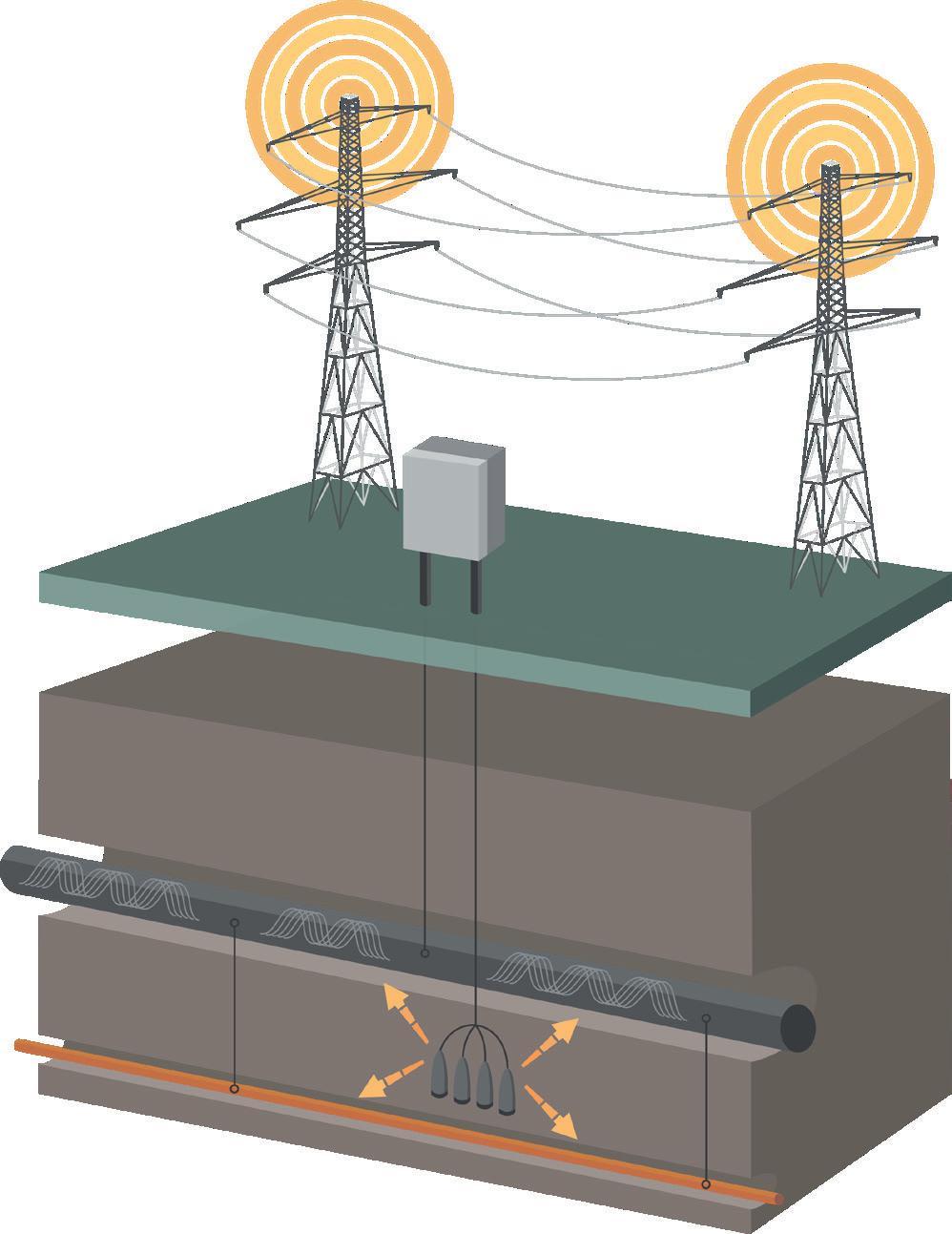
bonds requires the CP system to protect a significantly greater material surface area than it was designed to cover. As a result, it is often difficult to maintain adequate CP to protect the pipeline. Because of this, the pipeline and related equipment need to maintain effective earthing paths for safety, while also maintaining DC isolation so CP systems can effectively protect against corrosion.
This is where a decoupler comes in – maintaining DC isolation and ensuring the CP system can effectively protect against corrosion while also providing safety earthing and mitigation of induced or conducted AC.
Decouplers simultaneously perform two needed electrical functions: DC isolation and AC continuity for earthing. Installed between the protected structure and the earthing system, they isolate or block the flow of DC current (from the CP system) to the earthing system or other equipment. This thereby eliminates any negative influence on the CP system caused by the earthing system or neighbouring equipment. Yet, decouplers also provide safety earthing protection from induced AC voltage, AC faults, and lightning.
Solid-state decouplers have been industry standard since the early 2000s. A modern Dairyland decoupler consists of solid-state components in parallel with a large capacitor. The solid-state portion acts like a switch (but without any moving parts) that remains open during normal operating conditions to prevent AC and DC from passing and automatically closes during over-voltage conditions, such as AC faults or lightning. When the overvoltage condition passes, the device opens back up and continues to provide DC isolation. The capacitor allows steady-state AC current to pass continuously with very low AC voltage drop, while also preventing DC flow.
Because decouplers function with minimal need for human intervention, they are unlike other components of pipeline infrastructure. This is a significant benefit when installed in geographically remote and challenging environments.
However, not all decouplers are created equally and some will have greater maintenance requirements than others. When sourcing a decoupler, it should be certified by a credible third-party organisation as maintenance-free and fail-safe.
With these certifications in place, as Dairyland devices do, not only will your decoupler be maintenance-free, but if exposed to fault current values beyond its rating, these over-voltage protection devices will always fail safely and uneventfully in the shorted mode. This assures that over - voltage conditions will always be addressed.
) AC fault protection: AC fault current generated by a failure of nearby or connected electrical equipment is a safety hazard. This AC current can be transmitted via the pipeline, endangering nearby workers, or causing damage to the pipeline. When an AC fault occurs, the



Double Block & Bleed Line Stop System
Double Block and Bleed Safety / Single Stop Simplicity
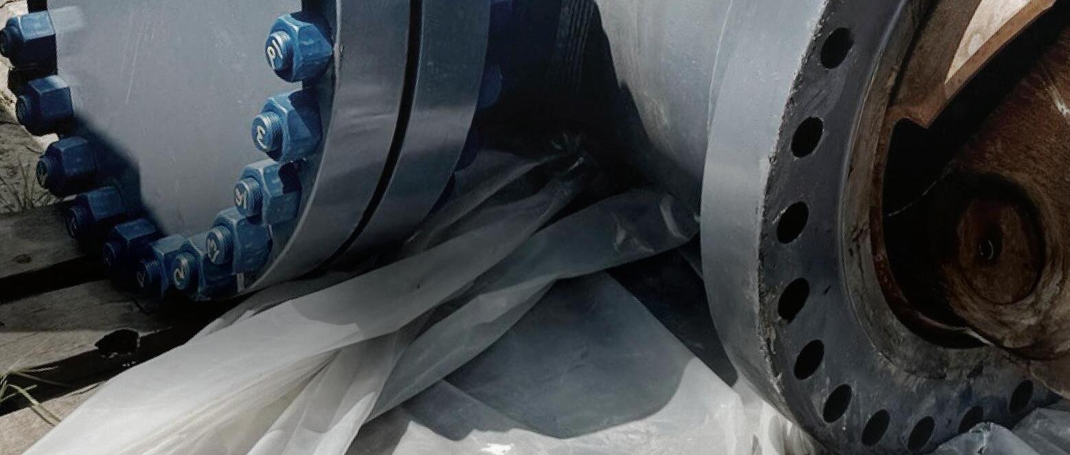
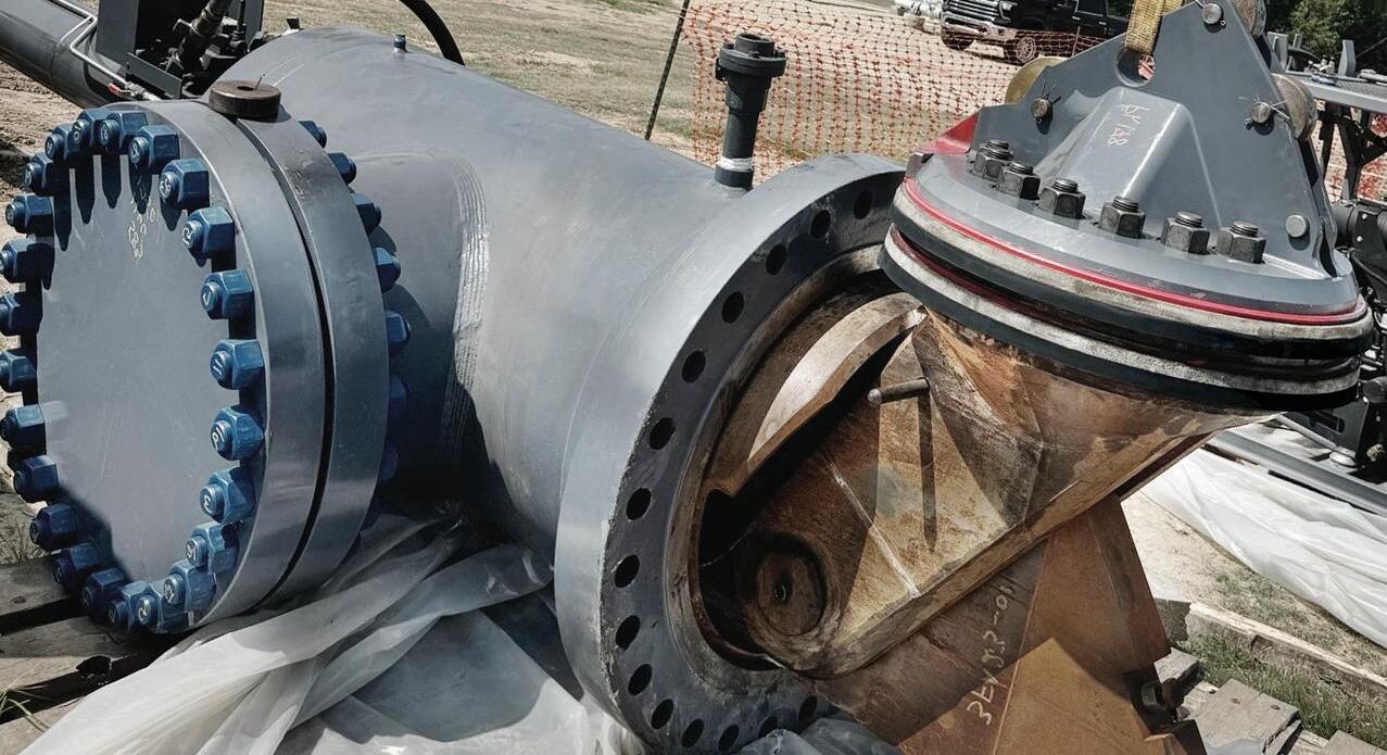
The new Dually TM Double Block & Bleed (DBB) Line Stop System combines the sealing security of DBB technology with the simplicity of a single seal line stop and avoids the downtime and rework problems DBB equipment with coupled heads or complicated hydraulics can create.
Dually’s compact design features a single, patent-pending dual seal, pivot-style plugging head with all its movement contained within the line stop fitting. The new design ensures more effective chip sweeping functionality by removing more debris that can interfere with a tight seal.
That means Dually is more maneuverable into and out of the pipeline than other DBB systems, and more reliable when it comes to first-time sealing success.
decoupler instantly conducts fault current to earthing system, carrying AC current away from the pipeline and limiting the AC voltage rise on the pipeline.
) Lightning protection: when a lightning strike occurs, it can present a safety hazard to personnel and pose
a risk to nearby pipelines. The decoupler behaves in the same way as it does during an AC fault. It safely channels the high surge current of the lightning to earthing system, protecting nearby workers and the pipeline. As soon as this event has ended, the decoupler automatically switches back to its DC isolation/cathodic protection role.
) Mitigation of induced AC current: as detailed earlier, many pipelines are buried along a shared ROW with overhead high-voltage power lines. Even during normal operating conditions, current from these power lines induces AC voltage and current flow in the nearby pipeline. This is not only a safety hazard to workers but can also cause corrosion issues.
Decoupling can be defined as: utilising a device that blocks direct current while providing alternating current continuity for safety earthing.
Globally, regulation surrounding the operation and maintenance of oil and gas pipeline infrastructure is both changing and increasing. This is not surprising when you consider that the combined length of existing pipeline infrastructure could circle the Earth 30 times. 1 These changes in regulation will only continue in response to the parallel demands of the energy transition and drive for efficiency.
In the US, the impressively named ‘Mega Rule’ is already impacting approximately 300 000 miles of existing onshore natural gas pipeline, and almost 20 000 miles of planned pipeline. The Mega Rule builds on and updates existing legislation designed to reinforce a risk management approach to the safety of natural gas transmission pipelines, natural gas distribution pipelines, and hazardous liquid transmission pipelines. Its third and final part became effective in February 2023, with a compliance deadline of February 2024. It clarifies integrity management regulations from corrosion control requirements and repair criteria to post extreme weather inspection and applies to onshore gas pipeline infrastructure spanning high consequence areas (HCA), and non-HCA.
In the European Union (EU) multiple regulations have been implemented to address maintenance of energy infrastructure; including pipeline corrosion prevention. These include the Pipeline Safety Directive (PSD), and the Seveso Directive. Regardless of jurisdiction, compliance with these regulations is firmly the responsibility of operating companies and can be challenging and costly.
Decouplers have a significant role to play in enabling pipeline operators to comply with these regulations where they apply, and to operate their pipelines in a safe, more efficient, and sustainable way. Decouplers are ensuring essential surveys are conducted effectively and safely, playing a key role in AC mitigation
applications. They effectively minimise voltage differences to safe levels for both personnel and equipment.
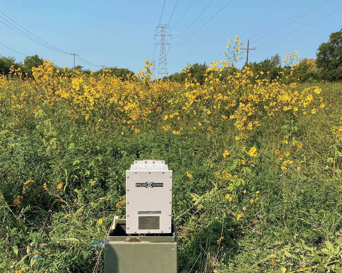
To meet these evolving demands, decouplers are becoming more advanced. Dairyland’s PCRX, for example, is the most sophisticated decoupler available globally. The PCRX provides typical decoupler functions with the additional benefit of electronically removing the effects of capacitance delays from interrupted surveys, including close-interval-surveys (CIS) – a key demand of the Mega Rule. This prevents the device from contributing to errors in potential readings. The PCRX overcomes capacitive effects, ensuring accurate and timely potential measurements. It does this without sacrificing the rugged over-voltage, AC mitigation, CP isolation, and safety earthing of Dairyland’s standard decoupling products.
Across the globe, oil and gas infrastructure is ageing, and pipelines are no exception to this. With a large percentage of US pipeline infrastructure estimated to be over 60 years old, it is not surprising that regulation surrounding maintenance has taken centre stage in recent years. 2 Similarly, in the UK, 50% of onshore pipelines are over 50 years old and subject to increased scrutiny, regulation, and good practice guidance. 3 Globally, extending the life of these assets, building them in compliance with regulation, and enabling safe sustainable operations, will require innovative technology and solutions. Decouplers can be added to a system through retrofitting –applied in pipeline upgrades and life extension projects and, of course, are essential elements of new-build infrastructure. PCRX, for example is proving to be an essential part of the modern CP system on pipelines and other protected structures for accurate CP readings while improving system performance and delivering the required safety protections.
Decouplers will continue to play a vital role in the safe and sustainable operation of pipelines around the world. Since 1983, Dairyland Electrical Industries has been applying the concepts of electrical isolation, grounding, and over-voltage protection to create standard and specialised electrical solutions to protect equipment and personnel. We will continue to champion our fail-safe, maintenance free, and
third party certified decouplers and put our expertise and technologies to work to ensure compliance, safety, and competitive edge for our customers. We are also committed to providing technical support to help you find exactly the solution you need, even if you do not end up needing our products.
References
1. https://globalenergymonitor.org/projects/global-oil-infrastructure-tracker/
2. https://us.anteagroup.com/news-events/blog/oil-gas-transportation-companiespipeline-integrity-management
3. https://www.ukopa.co.uk/wp-content/uploads/2020/05/GPG18-Remaining-LifeAssessment-Ed-1.pdf

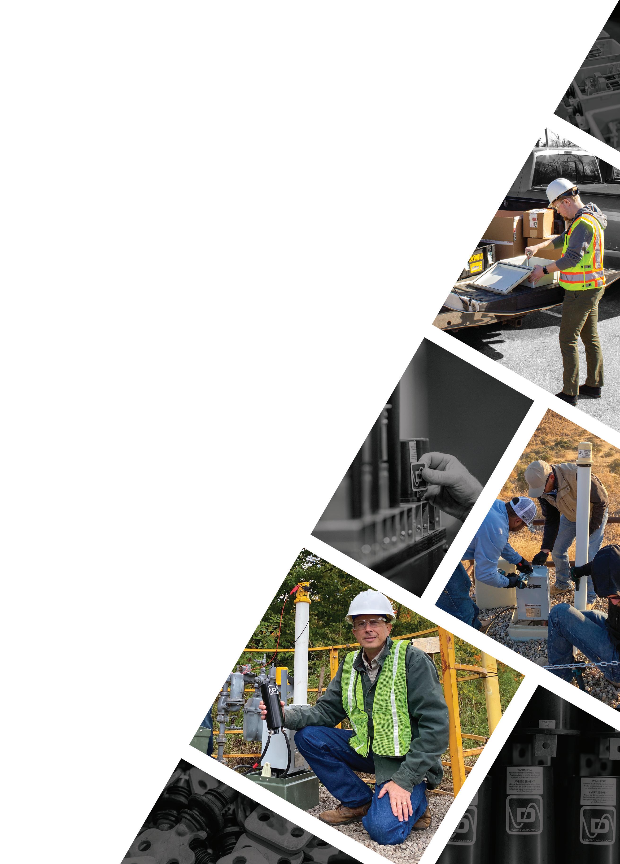

Dairyland decouplers are critical to cathodic protection systems — keeping workers and valuable assets safe from AC faults, lightning, and induced AC voltage — all while optimizing your CP systems.
We were the first company to introduce solid-state decoupling products to the industry, replacing the unreliable and dangerous polarization cells that exposed workers to shock hazards and highly caustic chemicals. In the decades that have followed, our solution-focused team ha s continued to deliver innovative decoupling products, solving critical problems across numerous applications and industries.
For more than forty years, Dairyland has pioneered new technologies and set new standards in the market. And we’re not done yet. If a solution to your problem does not yet exist, we’ll work to find one.
Let us help you find the right solution to your problem.
Matthew Green, Director of Technical Service, CSNRI, considers the past, present and future of engineered composite repair systems for pipelines.

pipe is a pipe, and they all look the same. But national transmission pipelines and piping networks within processing facilities and refineries are critical components of a country’s infrastructure. Transporting essential resources
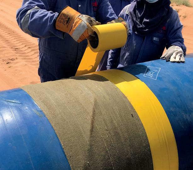
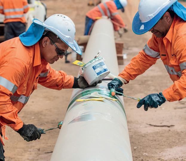
such as oil, gas, and water across vast distances, pipelines serve to provide a safe and successful journey for their contents. Maintaining pipeline integrity is paramount to ensuring safety, efficiency, and environmental protection remains at the highest levels. Traditional repair methods often involve extensive downtime, costly materials, and significant labour. However, for the past three decades, engineered composite repair systems have emerged as a solution, offering advantages in durability, cost-effectiveness, speed, and ease of application. CSNRI continues to push the boundaries on the capabilities and understanding of these highly beneficial materials.
The history of engineered composite repair systems for pipeline repair dates back to the late 20 th century, when the need for more effective, durable, and non-intrusive solutions became evident as ageing infrastructure began
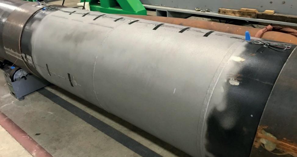
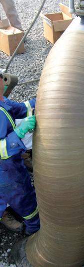
to pose significant challenges in various industries. Initially, traditional repair methods like welding and cutand-replace were common, but these approaches often resulted in extended downtime and increased costs. In the 1980s, advancements in composite materials, particularly fibre - reinforced polymers, began to transform the landscape of pipeline repair. These engineered composites offered superior strength-to-weight ratios, corrosion resistance, and the ability to conform to complex shapes. By the 1990s, standardised repair systems emerged, enabling operators to address pipeline integrity threats efficiently while minimising disruption to services. Followed in the next decade by the formalisation of industry standards such as the ASME PCC-2 Article 4 and ISO 24817, and the acceptance and use of these materials began to rapidly increase. Today, composite repair systems are widely recognised for their effectiveness and longevity, and they continue to evolve with advancements in material science and engineering, further enhancing their role in pipeline integrity management. Engineered composite repair systems consist of high - performance materials designed to restore the integrity of damaged pipelines. These systems typically utilise a combination of advanced fibres, resins, and adhesive technologies to create a composite material that is both strong and flexible. The most commonly utilised materials for these systems include:
) Fibreglass reinforced polymer (FRP): Offers a high strength-to-weight ratio and excellent corrosion resistance.
) Carbon fibre reinforced polymer (CFRP): Provides superior tensile strength and modulus, making it ideal for high-stress or high-strain applications.
The composite systems are engineered to bond to the existing pipeline substrate, effectively creating a new load-bearing structure that can withstand operational stresses. The bonding agents vary depending on the need of the repair system, but typically include polymers such as epoxies, urethanes, or polyesters.
Composite repair systems offer a range of significant advantages that make them increasingly popular as a staple in the toolbox of pipeline integrity programmes.
) Rapid deployment: One of the primary benefits of engineered composite repair systems is their quick application. Unlike traditional repair methods, which may require extensive excavation and replacement of pipeline sections, composite systems can often be applied directly in situ. This reduces downtime and allows for expedited restoration of service.
) Cost-effectiveness: Engineered composite repairs can be more economical than conventional methods. The materials and processes used can lead to significant cost savings, especially when factoring in reduced labour and operational disruption. Additionally, the longevity
of composite materials often translates into lower maintenance costs over time.
) Durability and longevity: Composite materials exhibit excellent resistance to corrosion, chemicals, and environmental factors. This inherent durability enhances the lifespan of the repaired pipeline, reducing the frequency and cost of future repairs, and in many cases, are considered permanent.
) Versatility: Composite repair systems can be applied to various types, sizes and geometries of pipelines, including those made of steel, fibreglass, and concrete. They are suitable for a range of environments, including offshore, underground, and industrial applications.
) Environmental safety: Composite systems are often less invasive than traditional methods. Their application typically requires minimal excavation, which reduces the risk of environmental disruption. Furthermore, many composite materials are designed to be environmentally friendly, contributing to safer operations.
A history of testing and validation
With three decades of testing and experience behind them, composite materials are continuing to prove their value. There have been a variety of ways in which today’s commercially available products have had their origins. Many have funded significant independent testing on their systems, but also the industry at large has had a hand in many testing programmes over the years. Multiple Joint Industry Programmes (JIPs) have been held and either fully or partially funded by pipeline owners, as well as repair system suppliers.
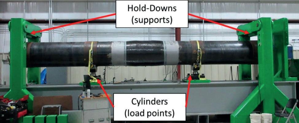
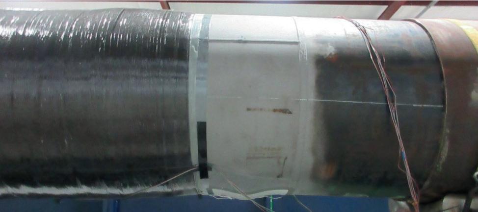
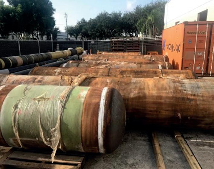
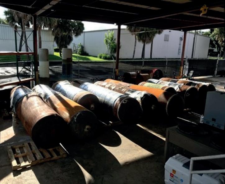
While the previously mentioned standards from ASME and ISO have a good basis of qualification testing, for the repair of transmission pipelines, there are a variety of defect-specific needs that are not fully addressed. Many of the testing programmes held over the years have been to validate the usage of composite repairs on these defect-specific scenarios, and in many cases, including the use of pressure cycling as part of the test method to determine the real-world effects on the repair system as it would be in service. This is especially critical for regulated pipelines. One such large programme was the PRCI (Pipeline Research Council International) research study, “Assuring the Permanency of Composite Systems for the Repair of Corrosion and Mechanical Damage (MATR-3-3) (MATR-3-4)” which was conducted to validate the long-term usage of composites. This project subjected a multitude of composite repairs to a 10 year study in full operational conditions, where many of the repairs maintained the integrity of 75% deep metal loss defects under 900 annual pressure cycles and then were subjected to a burst test where failure initiated outside of the repair.
Many other similar such programmes have been executed to either determine the viability of or quantify the effectiveness of composite repairs for specific defects. These have included:
) General external corrosion.
) Internal corrosion.
) Corrosion in weld seams.
) Mechanical damage.
) Cracking and crack-like defects.
testing.
) Axial reinforcement (geohazard, girth weld, and wrinkle bend).
While there have been significant programmes for corrosion and mechanical damage, some of the more recent testing mentioned has focused on crack-like defects, and axial reinforcements, specifically for reinforcing girth welds to prevent failure in potential geohazard events.
Theory and testing are a great foundation for technologies, but without real world usage, what good are they? Many independent testing programmes have been funded or co-funded by the pipeline operators who are looking to qualify or in some cases expand the scope of usage of composite repairs within their operations.
A pipeline company that had previously implemented composite repairs for various defects, including small-scale crack-like anomalies, undertook an evaluation to expand the application of composites to encompass longer defect lengths and interacting features in vintage seam welds. Composites had consistently demonstrated superior performance compared to traditional repair methods, and this extension of the application envelope for composites on seam weld anomalies was projected to yield significant economic benefits. Following a comprehensive testing programme utilising CSNRI’s Atlas carbon fibre repair system, the operator revised their Standard Operating Procedures (SOP) to include specifications for longer and interacting defects. This modification facilitated the successful execution of multiple repairs, thereby enhancing pipeline integrity and optimising maintenance expenditures.
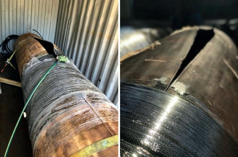
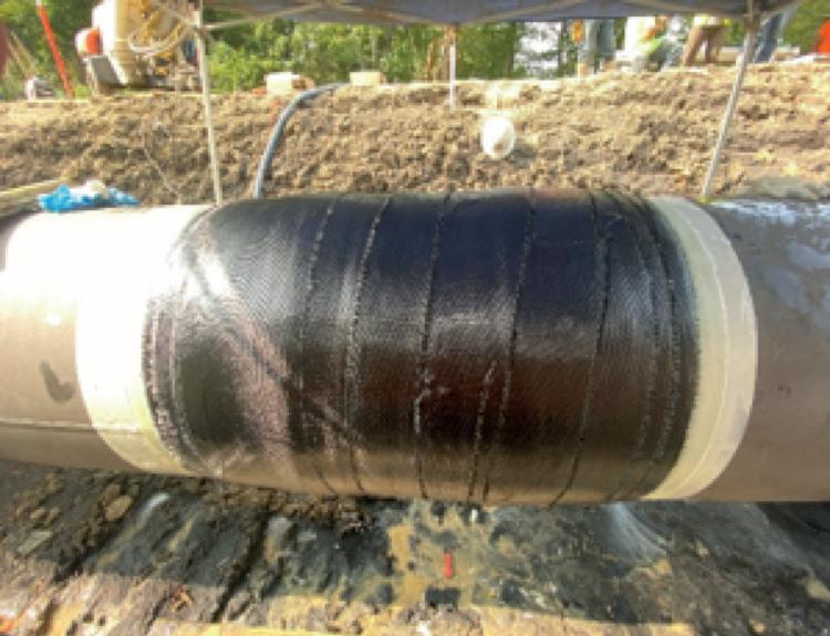
In a challenging geohazard area with multiple landslides occuring simultaeneously, a pipeline operator successfully utilised Atlas UA to reinforce its girth welds, eliminating the risk of a rupture during a landslide. Recognising the risks posed by shifting soils and potential landslides, the engineering team implemented Atlas UA’s patented advanced composite technology, which provided exceptional strength in the axial direction of the pipeline, improving the tensile strain capacity of the girth weld. This solution not only improved the welds’ resistance to environmental stresses but also streamlined the repair process, significantly reducing downtime. The application of Atlas UA exemplified a proactive approach to pipeline integrity management against emerging integrity threats, ultimately safeguarding both the pipeline’s operation and the surrounding ecosystem.
While engineered composite repair systems offer numerous advantages, there are also considerations that engineers and operators must consider to ensure their successful implementation into their procedures. Full testing validation and qualification should be a given as discussed above, but what else may need to be considered?
) Material and environmental compatibility: Composites are a versatile technology, and by implementing different types of polymers, they can accomplish a wide range of chemical and environmental compatibility. Thorough testing is essential to avoid adverse reactions that could compromise repair integrity based on the operating environment and conditions.

Environmental conditions, such as temperature and humidity, can impact the curing process and overall effectiveness of composite repairs. Proper planning and monitoring are crucial during application. Whether it is chemical or temperature, knowing the limits and functionality of the repair system and its components is vital.
) Regulatory compliance: Engineers must ensure that all repairs comply with industry regulations and standards. This may involve documentation, testing, and certification processes that can be time-consuming. By implementing a sound SOP around the use of composite repair systems, it can provide a working structure that allows for the effective implementation of these materials into integrity management plans.
) Training and expertise: Successful application of composite repair systems requires trained personnel with expertise in the materials and techniques used. Investment in time for proper training is necessary to maximise the benefits of these systems. CSNRI has pioneered this effort to provide the best training programmes and platforms for the successful training of all installers of their composite repair systems.
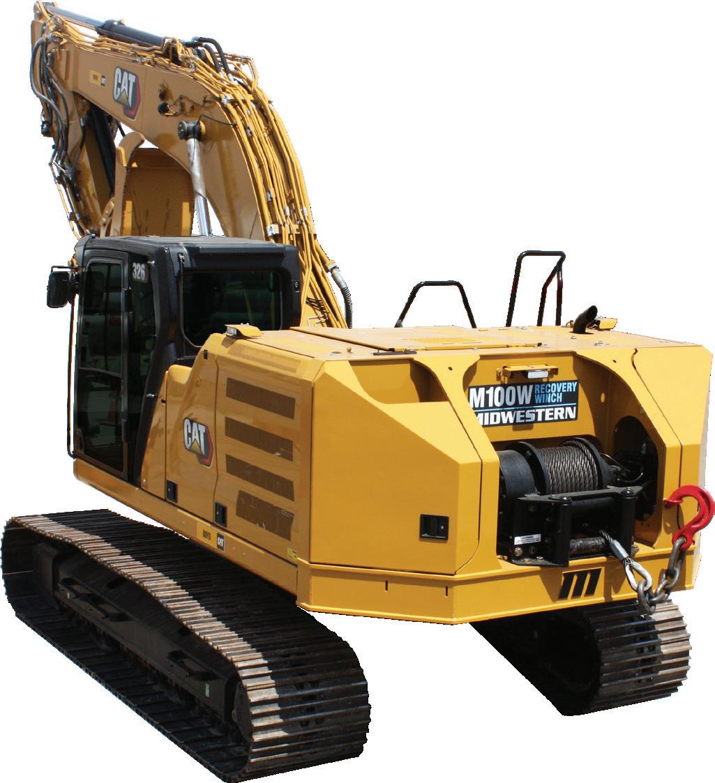
The NEW counterweight mounted M100W recovery winch is Midwestern’s latest innovation in excavator attachments. This system replaces the original counterweight, making productive use of what was literally dead weight. Advantages over mounting a winch on the track frame include greater ground clearance, and higher pull location to lift and pull at the same time. Other features include light and camera mounts, ladder and locking swing-out doors, and additional storage.
Make the most out of your excavator with a MIDWESTERN M100W winch.
The evolution of engineered composite repair systems has transformed pipeline maintenance, offering significant advantages over traditional methods. As the demand for reliable infrastructure increases, the application of these advanced materials will play a vital role in ensuring the safety and efficiency of pipelines. The successful testing and validation of composite systems have established a solid foundation for their use in a variety of scenarios, from addressing crack-like defects to reinforcing critical welds in geohazard-prone regions. As operators continue to adopt these innovative solutions, they must also remain vigilant about the considerations necessary for effective implementation. Ensuring material compatibility, adhering to regulatory standards, and providing thorough training for personnel are crucial steps in maximising the benefits of composite repairs. Ultimately, the strategic deployment of engineered composites not only enhances pipeline integrity but also contributes to long-term economic savings and environmental protection, solidifying their place as a cornerstone of modern pipeline integrity management practices. As the technology advances, further innovations are expected, promising even greater enhancements in pipeline reliability and performance.

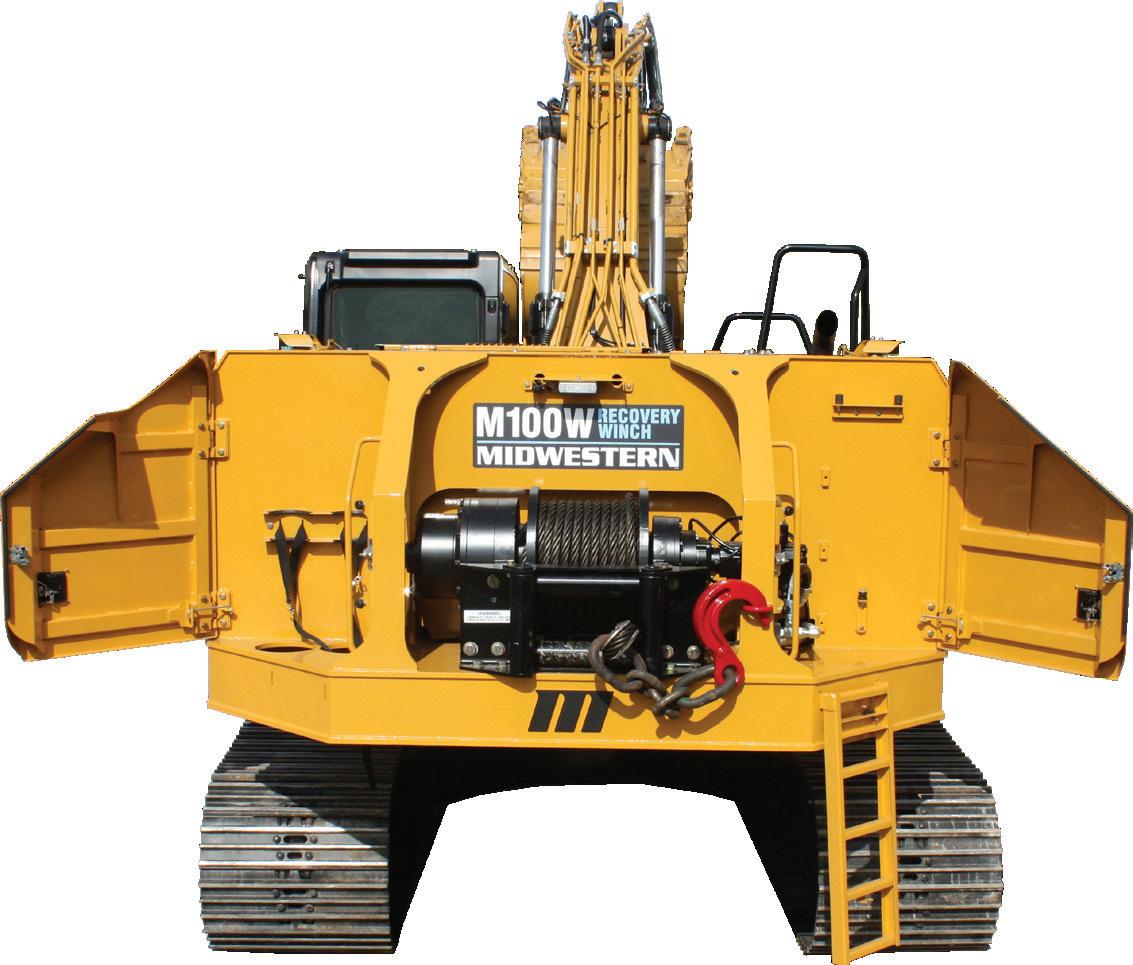
100,000 lb Line Pull
World Pipelines talks welding with some industry experts, covering recent projects, weld integrity, welder skills and safety and more.
Maxwell, Manager of In-Service Welding, Weldfit.
Jürgen Ganglbauer, Solution & Product Management Welding Automation, Fronius International GmbH.
Discuss a recent technological enhancement that has benefitted your welding equipment or welding capabilities.
Frede Maxwell, Weldfit : Advancements in induction heating technologies, wherein a magnetic field is used to heat conductive materials, have greatly expanded its use in WeldFit’s live pipeline in-service welding business. We have found in this service, which requires our specialised technicians to weld split tees for hot tapping and line stopping operations on live pipelines, that controlled heating is more often a requirement, especially on high-flow pipelines to help reduce
post weld hardness. This highly efficient technology also reduces overall heating times and requires less equipment on site than other heating methods. Additionally, computer-based finite element analysis (FEA) modelling software has enhanced the predictability of WeldFit’s in-service welding results. Our team regularly uses this technology to provide consistent guidelines for welding parameters to help mitigate potential unwanted post-weld conditions.
Jürgen Ganglbauer, Fronius International: Fronius is one of the world’s leading manufacturers of overlay welding
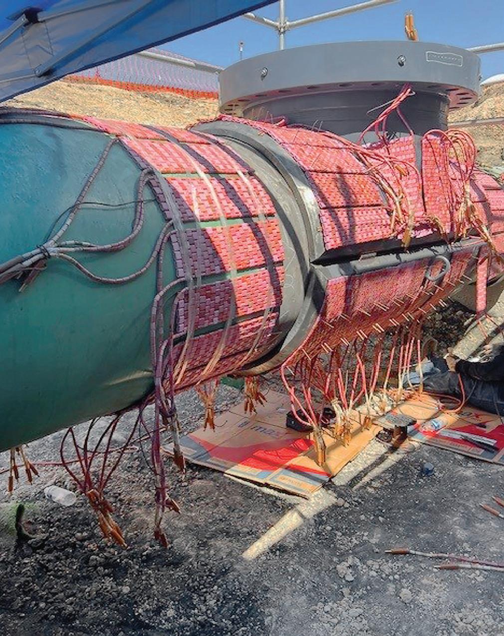
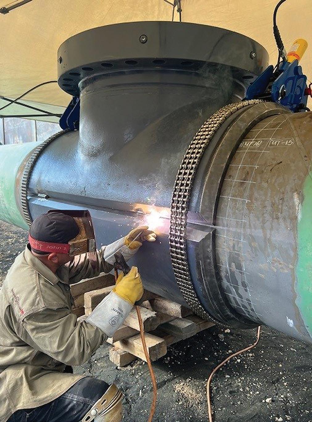
systems and continues to bring new innovations to the market, such as the retrofittable SpeedClad 2.0 process, which received the Excellence in Welding Award from the American Welding Society at FABTECH 2023. SpeedClad 2.0 is significantly more cost-effective than the pulsed TIG hot wire process. This innovation stands out due to its high deposition rate, impressive speed and low shielding gas consumption.
The HMI-T21 system control, which operates all the cladding systems, is ready for Industry 5.0 with a large, intuitive 21 in. touchscreen, multi-user accounts with individually assigned permissions, real-time process visualisation, on-the-fly parameter adjustments, and innovative functions such as X-Ray View, Component Editor, Bore-to-Bore Advanced, real-time actual value monitoring, and STEP file import. And, of course, the system offers remote maintenance capabilities. The X-Ray View provides a transparent outline of the component, giving the operator an excellent overview. The Bore-toBore Advanced function provides assistance when welding multiple offset transverse holes at non-90° angles or flanges with holes.
Outline the scope of a recent welding project (or upcoming one) for oil/gas pipelines.
Frede Maxwell, Weldfit: WeldFit successfully executed a complex in-service welding project on a high-pressure, high-flow gas pipeline. The operator was preparing to carry out an expansion project that would boost the throughput capacity of one of its natural gas transportation systems to more than 2.5 billion ft 3/d, an increase of more than 500 million ft 3/d. To support this expansion, the company contracted WeldFit to carry out 13 live-line fitting welding jobs at nine sites along the target pipeline – all while keeping product moving at an operating pressure of 1440 psi and flowrate of 42 ft/sec. without any interruptions.
Prior to executing this job, WeldFit developed specialised welding procedures and used advanced techniques to manage heat dispersion and temperature fluctuations caused by the pipeline’s operating conditions.
Jürgen Ganglbauer, Fronius International: The QMaster Editor is particularly helpful in achieving consistent weld quality. It is used to define limits (QMaster Limits) for welding parameters such as current, voltage, wire speed, and much more. Another quality-related function is AVC (Arc Voltage Control), which regulates both the electrode distance to the component during the welding process and the arc voltage. To ensure optimal starting conditions for the AVC function at the beginning of the welding process, a certain distance must be maintained between the welding torch and the component. This distance can be adjusted using the Touch and Retract function.
Frede Maxwell, Weldfit: WeldFit maintains a diligent continuity database for its in-service welders. All welder qualifications are provided by a third-party testing lab, and our welder integrity extends down to the rig truck
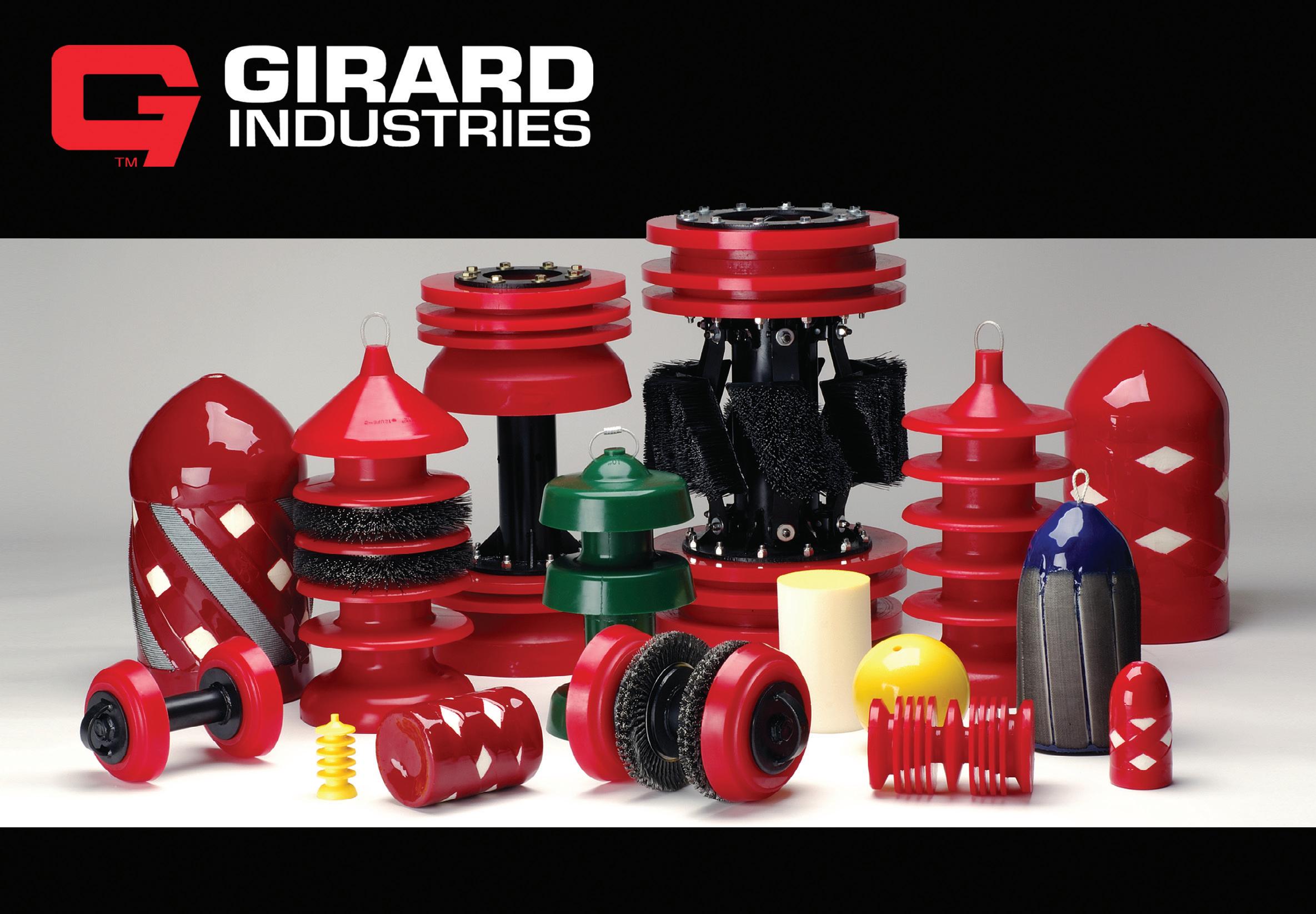

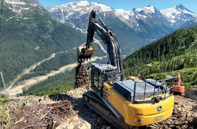
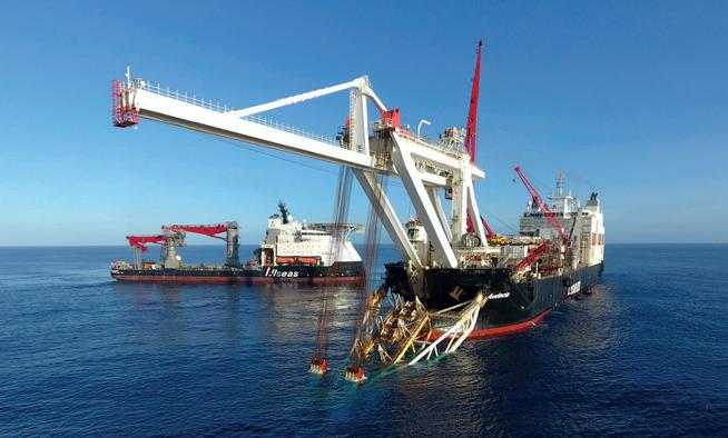
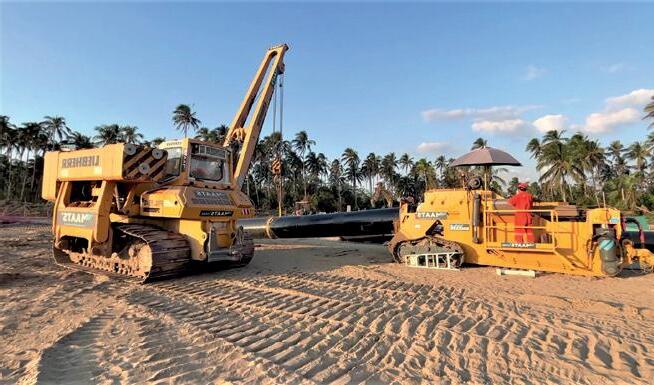
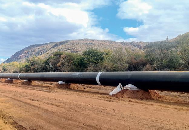
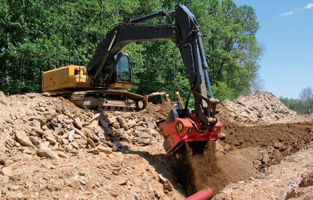

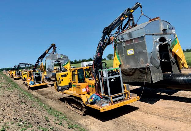
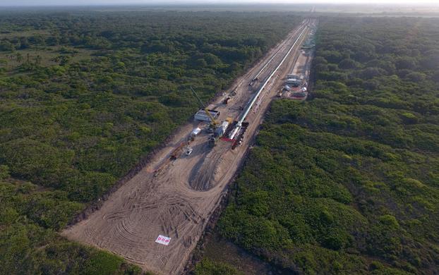
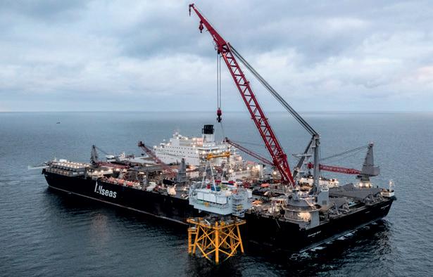
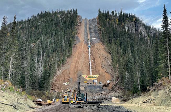
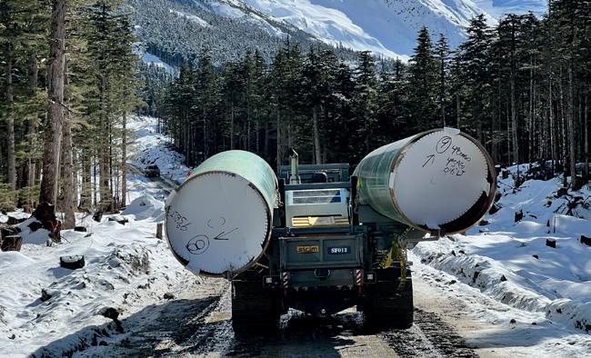
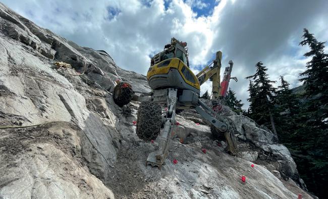
level. WeldFit has a rig truck standard and requires annual inspections to ensure all our welders meet prescribed expectations.
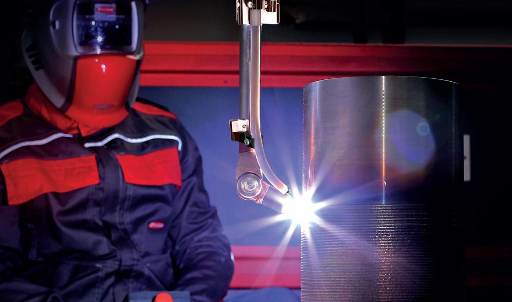
Describe an industry trend that has affected your business this year.
Frede Maxwell, Weldfit: There are a few trends that have had an impact on our business, starting with the recent uptick in pipeline operating company mergers and acquisitions. This has driven an increase in the number of pipeline crossovers and likewise, the number of in-service welding jobs associated with the required hot taps. Additionally, mechanical integrity inspections have increasingly required more anomaly repairs requiring the installation and welding of more fittings for line stops and bypasses. Lastly, pipeline operators are requiring more reliable line stops with redundant seals. Traditionally, this double block and bleed (DBB) setup has been accomplished by welding two line stop fittings on either side of the pipeline isolation. With the introduction of the WeldFit Dually DBB line stop system, only one fitting is required on each side to initiate the required isolation.
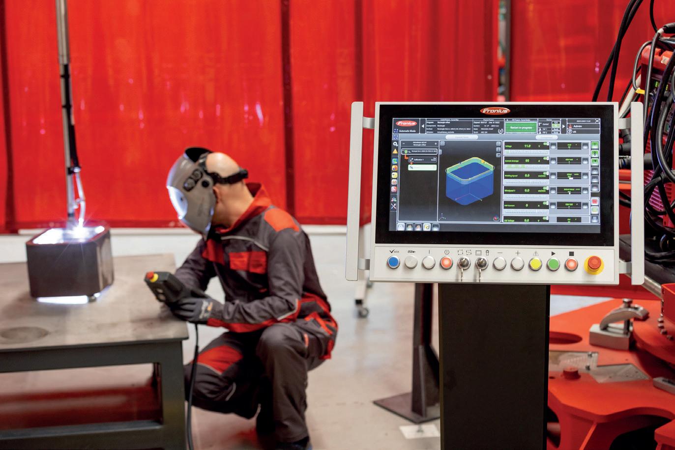
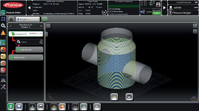
How are you addressing: improving welder skills, safety and/or documentation?
Frede Maxwell, Weldfit: WeldFit maintains mandatory safety training and in-service welder skill testing for all its welders. In addition to requiring our welders to obtain all applicable operator qualifications (OQs), we conduct background checks and perform drug screening for all technicians and welders. Lastly, WeldFit has an in-service quality programme that meets both API and ASME code requirements. In API 1104 Apx.B one of the essential variables requires an assessment of the In-Service Weld thermal severity. To meet this requirement as well as adding value to our service, we provide an In-Service Weld Assessment and Approval-to-Weld Review before each weld can begin.
Jürgen Ganglbauer, Fronius International: All Fronius cladding systems comply with the European Machinery Directive. The Machinery Directive 2006/42/EC is one of the most important pieces of legislation harmonising the essential safety requirements for machinery in the European Union. It describes uniform safety and health requirements for the interaction between man and machine. The Directive ensures a high level of protection for workers and citizens inside and outside the EU. All machines used in the European Economic Area are subject to the EU Machinery Directive and must therefore be CE certified.
Simon Bell, iNPIPE PRODUCTS, discusses what type and frequency of pigging is required in order to achieve optimum integrity and efficiency of a pipeline.
t is widely accepted that the purpose of pigging is to help maintain the integrity and optimum efficiency of a pipeline. Although this statement is accepted, the next conundrum is what type and frequency of pigging is required in order to achieve this ultimate goal and safeguard a multi-million-dollar capital investment. Like any investment, a return on the initial investment is required by the investor; in the case of a pipeline, this relies upon

additional operational investment over the course of the lifetime to maximise flow and to minimise deterioration.
To put some numbers into context, consider a 600 mm pipeline that experiences a 5% (30 mm) reduction in diameter due to debris buildup. This reduction would equate to a 10% decrease in flow. To restore the flow to its original rate, the pressure would need to be increased by approximately 30%.
These assumptions are based on the premise of a uniform deposit, which is highly unlikely. Additionally, the resulting turbulent flow can lead to an effective reduction
of nearly 15%, culminating in a total throughput reduction of 35%. To counteract this knock-on effect, the pressure would need to be increased by more than 140%, which may exceed the pipeline’s design specifications and the maximum allowable operating pressure (MAOP).
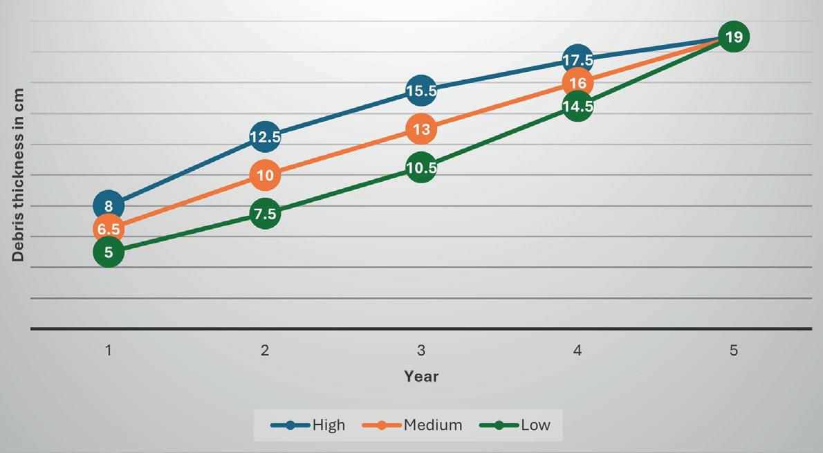
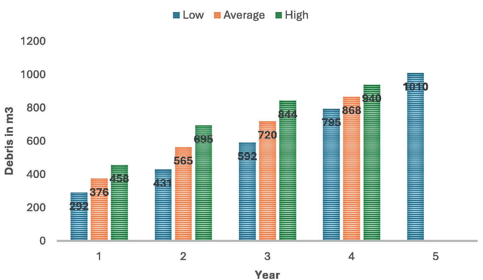
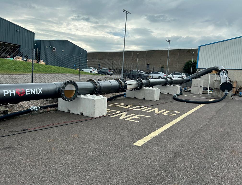
The effectiveness of any theoretical pigging programme depends upon the pigging programme and the effectiveness of the different pigs that are used. Pig type selection and frequency depends very much upon the type of deposit to be removed, and this can alter significantly with time as the pipeline ages and flow alters. A study around this problem was conducted on the Forties pipeline located in the North Sea which demonstrated that friction increased by 4.2%/d if the pipeline was not pigged.
It is widely accepted that pipelines must be cleaned to ensure optimal flow and minimise corrosion. However, the critical question is: how clean is ‘clean’? This is where the debris mapping tool can greatly assist by identifying the locations of deposits and measuring the amount of debris accumulated or the rate of accumulation from periodic runs through the pipeline.
This type of informative tool can be used throughout the lifetime of the pipeline including pre-commissioning, as it can be used to validate the as-built pipeline and validate the fit-forpurpose functionality of a new pipeline. These tools provide far more information than traditional gauging pigs, which are fitted with an aluminium gauge plate typically sized to 95% of the internal diameter. While a gauge pig indicates that there is an obstruction, it does not specify its location.
In contrast, running a debris mapping tool with high-definition (HD) caliper mapping capabilities offers numerous benefits to the operator. It establishes a datum for ovality, excessive weld penetration and valve functionality, while also providing valuable data in cases where the pipeline may have been dented or damaged during installation. Moreover, it offers peace of mind that the pipeline is clean, as the tool delivers precise information on the location, orientation and dimensions of any potential damage.
It also provides validation for the EPC contractor that the pipeline was delivered in pristine condition with the functionality validated. Once this initial run has been completed, it can be used and compared with subsequent runs, which will give real understanding of the history of the pipeline and flag up differences very quickly.
Ongoing product development and advancements in technology have made it possible for debris mapping tools to be equipped with HD video and lighting. This enhancement allows the tools to provide accurate internal measurements alongside video footage, enabling the creation of reliable location and orientation maps of features and anomalies. This visual aspect offers a high level of confidence that the reported data accurately
reflects the pipeline’s current state. This capability is particularly beneficial for inspecting compression composite seals in composite pipelines, especially in larger pipelines. Furthermore, improvements in sensor technology have led to a modular, scalable design, allowing these tools to accommodate pipelines ranging from 16 in. to 90 in. and beyond.
Debris removal and mapping needs to be carefully considered, particularly on the larger pipelines as often the volume of debris in pipelines infrequently or seldom pigged far exceeds the receiving capabilities of the system. A progressive approach to debris removal needs to be considered in this instance, and validation of the pigging tool design and pigging regime needs to ensure that exactly the correct amount of debris is systematically removed to avoid complications and potential flow interruption.
The iNPIPE PRODUCTS Phoenix mapping tool utilises ongoing innovation along with a range of the latest sensors and software to provide customers with trusted data and analysis. This assists pipeline owners in understanding the ongoing operating conditions within their pipelines.
It captures up to 144 000 data points every second where required, delivering an unparalleled volume and high-definition precision of data across a pipeline network. High-definition debris measurements are generated from hall-effect sensors. High-definition debris measurements are generated using hall-effect sensors, which detect the presence and magnitude of a magnetic field. Optimal positioning within a bespoke caliper arm design is key to the accuracy of the data recorded.
During the tool’s development, exhaustive positioning options were tested to ensure the best performance. It was discovered that positioning both the debris and caliper sensors within the same arm arrangement correlates data points in tandem, significantly enhancing accuracy. This setup eliminates inaccuracies that can arise from mapping data across multiple sensors with varying tolerances, ultimately providing more precise and reliable results. This high-definition measurement capability offers a significant advantage over other traditional caliper tools.
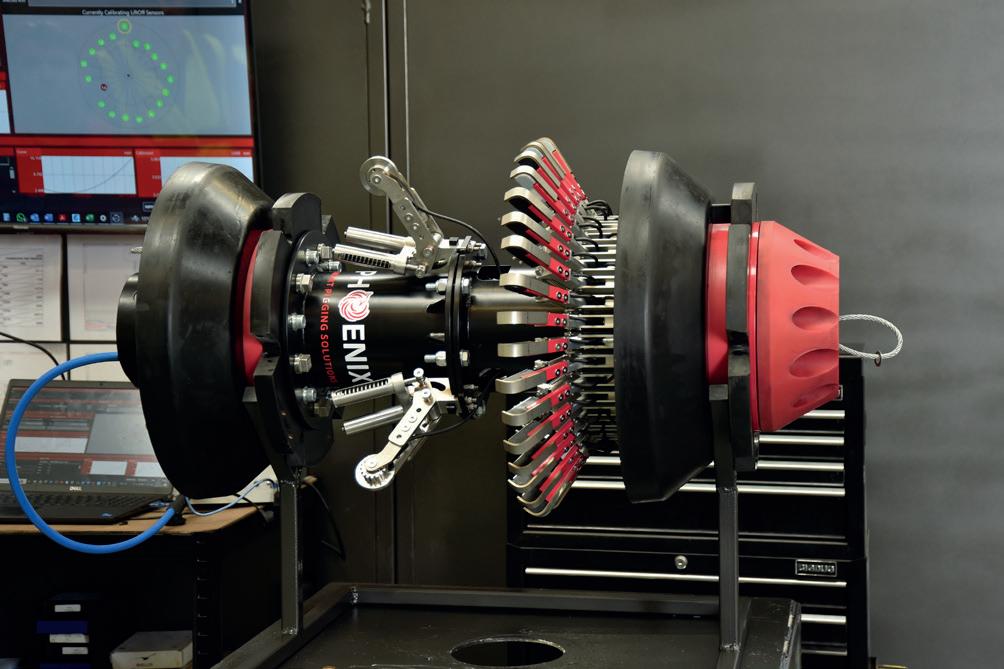
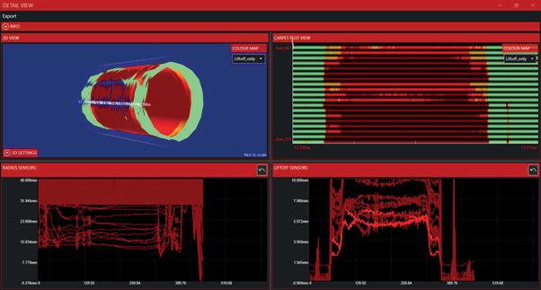
Phoenix provides pipeline operators with a comprehensive 360° internal assessment, identifying everything from debris and damage to temperature fluctuations and internal joint measurements. This allows operators to make informed and validated decisions about the effectiveness of cleaning, the type of pigging tool required, and the necessary pigging frequency. Regular runs can also help build a full understanding of potential deposition over the pipeline’s lifetime, particularly if used during the pre-commissioning stage.
The innovative software dashboard uploads live data from the logger in minutes, allowing it to be immediately interrogated and presented in a graphical format. The overview screen highlights areas of immediate concern without the need for a data analyst on-site, while also
enabling engineers to focus on specific features directly from the overview. This provides the customer with critical data almost instantly. These features offer immediate access to all data, along with the ability to explore and analyse any pipeline feature, anomaly or change in real time.
In addition to debris mapping, Phoenix Vision offers visual inspection of pipeline internals, providing both debris monitoring and assessment of pipeline condition, often as part of a pigging regime. The integrated camera and LED lights can be mounted within Phoenix or independently within mandrel body pigs or foam pigs, depending on the application.

Jeremy Silber, Eric Yang, Christopher Lepore and Yash Yadav, Delta Energy Group, USA, compare pipeline leak detection technologies and the challenges and misconception of fibre optic leak detection.

ipeline leak detection has become a critical aspect of modern infrastructure management, with far-reaching implications for safety, environmental protection, and economic stability. With over 2.5 million miles of oil and gas pipelines across the United States alone, there is an ongoing need for the safe operation and monitoring of these systems.
Leaks can occur for various reasons, and they are often the result of a combination of factors, including corrosion, mechanical damage, material defects, or thirdparty damage. As of June 2022, over 2600 hazardous gas pipeline leaks in the United States caused more than US$4 billion in damages and emergency services, killed 122 people, and released 26.6 billion ft3 of fuel such as methane or carbon dioxide into the atmosphere.1 These only included detectable major leaks reported to the government, while minor leaks can go undetected and unrepaired for years. Without proper leak detection technologies, these minor leaks will go unnoticed until it is too late to repair them.
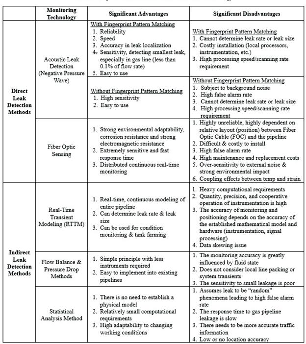
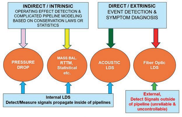
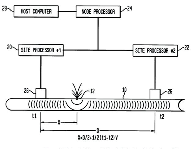
Detecting and responding to pipeline leaks immediately upon their occurrence is imperative to reducing the risk of catastrophic consequences such as environmental disasters, financial losses, and public safety. Since most of the pipelines are buried underground, it is also critically important to rapidly and accurately locate the leak and take swift action before it develops into a catastrophically large leak. The on-line real-time methods to detect and locate a leak generally fall under one of two different types of systems: indirect (intrinsic) systems which use mathematical models based on the fundamental laws of conservation and fluid dynamics, or direct (extrinsic) systems which directly detect the released fluid or measure signals created by the leak. Additionally, leak detection technology can also be classified either as internal, meaning they detect signals inside the pipeline pressure boundary, or external, which detect signals outside of the pipeline. Figure 1 shows a diagram breaking down the different leak detection technologies, including commonly used systems such as RTTM, acoustic, and fibre optic leak detection. Table 1 highlights the pros and cons of each of the systems.
Acoustic leak detection operates by detecting sound waves generated by the leak due to the breakdown of a pressure boundary. These acoustic signals are picked up by highly sensitive sensors and identified by various data processing techniques and advanced filters. The most effective data processing and acoustic leak identification technique so far is the acoustic fingerprint matching method, which requires not only a large database of leak acoustic signals to generate the matching mask, but also knowledge of the variation of mask as the acoustic signals propagate along the pipelines.2 The system continuously monitors the pipeline at an extremely high scanning rate. The data is processed within a local site processor using advanced algorithms to analyse the sound patterns to detect anomalies or matching acoustic fingerprint that suggest a leak. The central processor is responsible for confirming and locating the leak with multilayer, multi-iteration algorithms and time-of-flight computation based on GPS time stamps from two or more local processors. This method is commonly used in both liquid, gas, and multiphase pipelines due to its ability to identify subtle changes in acoustic signatures.
One of the main strengths of acoustic leak detection is its high reliability. Unlike other methods that may depend on dynamic relationships between pressure and flow, acoustic leak detection systems (ALDS) can detect leaks solely on the acoustic pressure wave generated and propagate within the pipeline guided and protected by the pipe walls. The physics-driven advanced data processing algorithms with unique leak acoustic fingerprint are effective and reliable in identifying even small leaks. Additionally, the speed of detection is another significant advantage. Acoustic systems provide near-instantaneous alerts, allowing pipeline operators to respond swiftly to leaks, minimising environmental damage and loss of product.
One limitation of ALDS is that while it can rapidly and reliably detect a leak, it can only estimate the leak rate by the signal strength and is unable to accurately quantify the size or rate of the leak.
One major challenge for ALDS is positive identification of leak generated acoustic signals under extremely noisy environments. One advanced technology involving acoustic fingerprint matching against mask developed from large databases for various transporting fluids has been proven to be the most effective and reliable approach.2 Unlike other acoustic leak detection methods that rely solely on passive background noise filtering such as frequency analysis, this approach allows positive identification of the leak based on its unique fingerprint. This method is superior as it reduces the likelihood of false positives by allowing for more precise identification of leaks, even in noisy environments or under varying operational conditions.
Fibre optics has recently emerged as an alternative technology in the field of leak detection mainly due to its combined use for communication. This technology leverages the unique properties of optical fibres, which are thin strands of glass or plastic capable of transmitting light over long distances with minimal signal loss. The most commonly used fibre optic leak detection technology is distributed fibre optic sensing (DFOS) which uses distributed sensors, detecting various environmental changes in real-time by analysing the light signals transmitted through the fibre. Fibre optic cables (FBC) transmit light signals that are scattered or reflected back due to small changes in the environmental conditions such
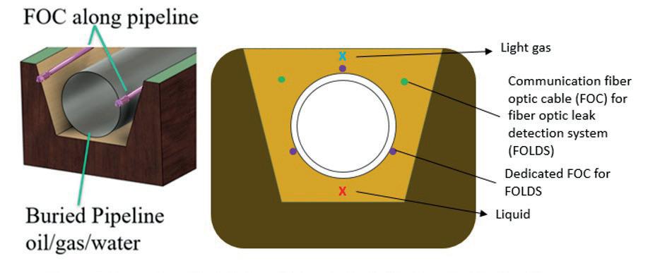
as temperature, strain, vibration, and acoustics. Several algorithms can be used to analyse the backscattered light, including Raman, Rayleigh, Brillouin, Fibre Optic Bragg (FBG) each providing unique advantages in sensing different types of changes along the fibre optic cable including light intensity, wavelength changes, frequency shifts, or phase changes. Figure 3 shows a typical installation for fibre optic cables for different applications used for leak detection.
Fibre optics are widely recognised for their speed and sensitivity in communication and sensing applications, due to their ability to transmit data at high rates over long distances with minimal signal degradation. However, fibre optic sensing is not suitable for pipeline leak detection applications as it presents several challenges that limit its effectiveness, particularly due to its sensitivity and the complex environmental conditions in which it operates. Due to the difference in material between fibre optic cable and the pipeline
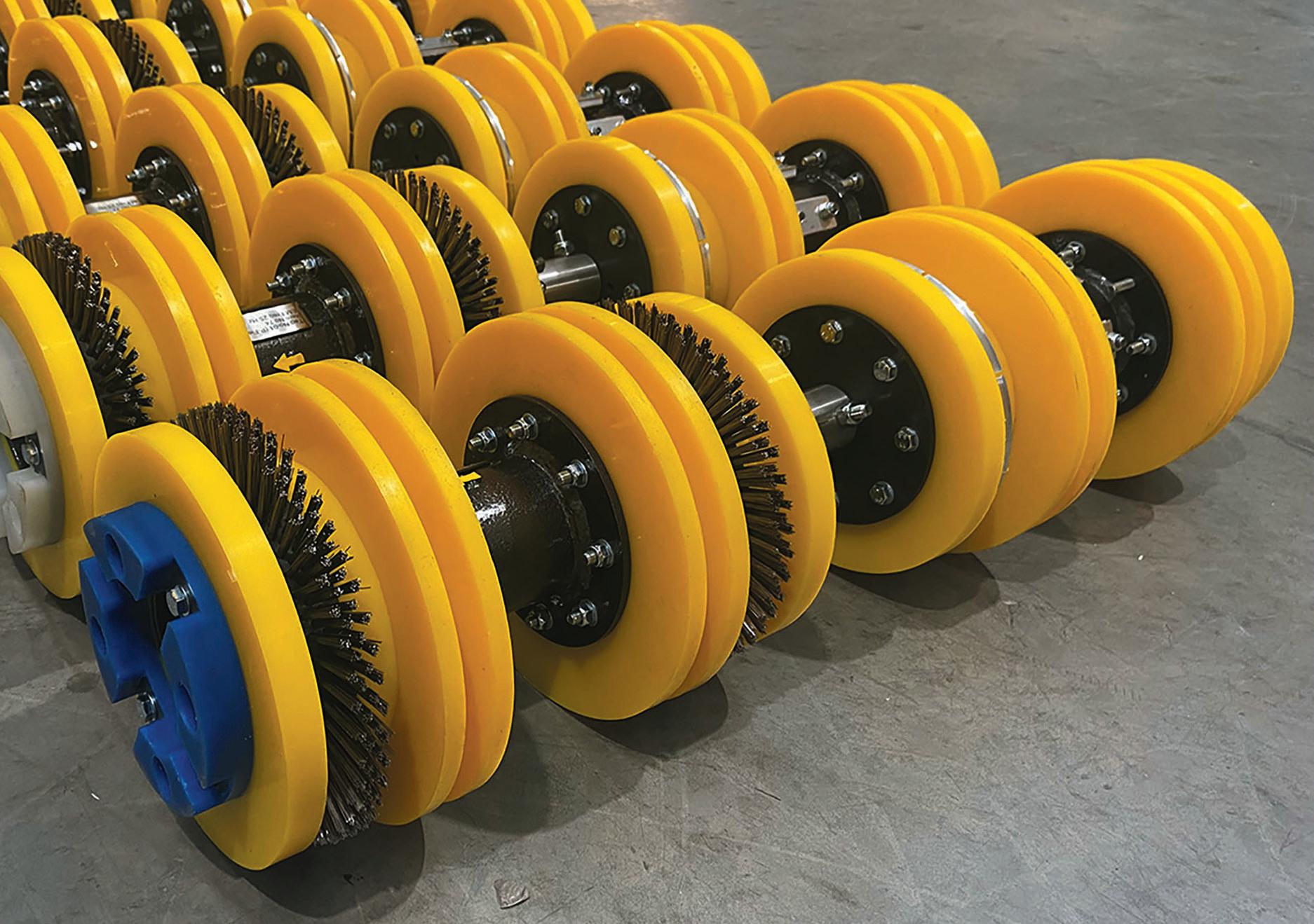

Articulated pigs are typically designed to pass pipeline wye connections whilst also negotiating tight bend radius. They are also used to pass oversized features (such as ball valves, check valves or connector hubs).
This type of pig is also highly efficient in long run, dewatering/flooding and heavy duty cleaning operations as well as dual-diameter applications.
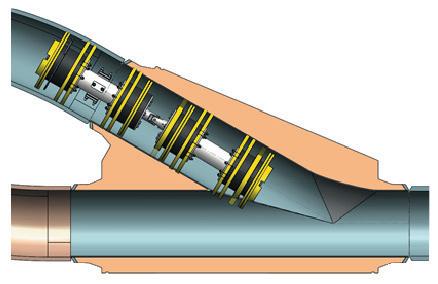
itself, attachment directly on the pipeline for strain measurement is extremely challenging over long distances. Instead, communication fibre optic cables installed at a certain distance away from the pipeline at a certain direction can be used for added leak detection function for cost saving. Unfortunately, this approach often leads to extremely unreliable performance with both high false negatives (easy to miss real leak) and false positives (false alarms). The detection process is highly dependent on the orientation and proximity of the optical cable to the leak discharge direction. Fibre optic sensors can only effectively detect leaks that discharge directly toward the buried cable, within a limited range and in a specific direction. This limitation can lead to extremely high false negative rates, with the system potentially missing up to 80% or more of actual leaks.
Moreover, the sensitive nature of the fibre optic cable makes it vulnerable to environmental noise from external factors such as rain, temperature fluctuations, any external contamination, and mechanical disturbances, all of which can result in high false positive rates. The system is also susceptible to damage from external chemicals and environmental changes such as landslides, storms, earthquakes, and railroad noise or river crossings. Under such harsh conditions, the fibre optic cable may break before the pipeline and cannot reliably provide the important leak detection and location function under these critical conditions (over 70% of leaks occur under these types of conditions).
While there are many different types of indirect leak detection technology, for the most part they all follow the same fundamental principle of using mathematical computations based on conservation laws to determine when a leak has occurred within a pipeline. A few of the most common examples of this technology are flow balance systems, real time transient modelling (RTTM) systems, and statistical based approaches. Unfortunately, each of these systems has a few key limitations that prevent them from being effective alternatives to the direct leak detection methods. Methods like the flow balance approach often struggle achieving satisfactory sensitivity requirements and can be inaccurate due to neglecting of local line packing or system transients. RTTM
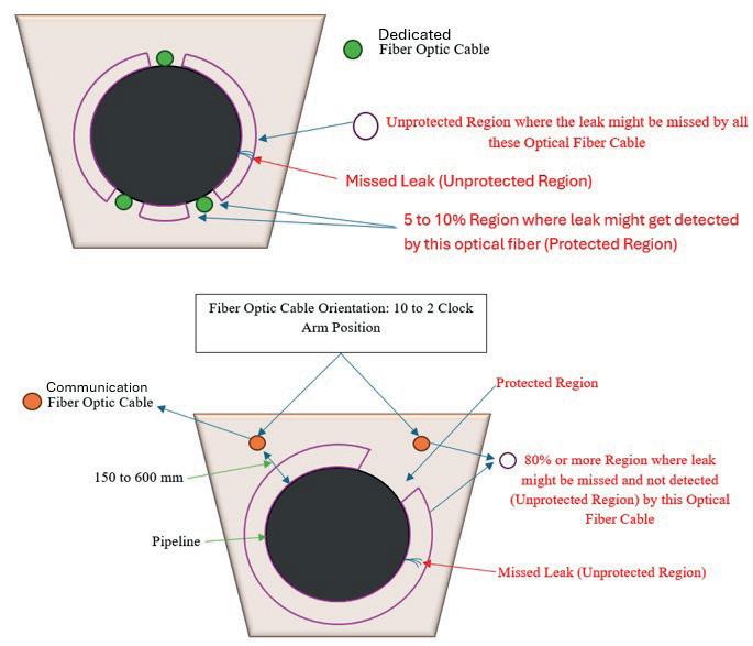
systems may account for transient characteristics and the effect of line packing, however this causes the computational load to be exceedingly high, reducing the speed at which leaks can be detected. Accuracy of the systems is also severely capped by the accuracy of the instrumentation and mathematical model being used. Statistical methods that treat the leak as a random phenomenon and use data analysis to identify changes in patterns of hydraulic parameters that indicate a leak are fundamentally flawed by the fact that a leak is a hydraulic event that cannot be analysed and reliably predicted based on probability, making such systems subject to high false alarm rates and the possibility of missing leaks.
Overall, indirect leak detection methods fail to achieve the same levels of accuracy, reliability, precision, and speed when compared to their direct leak detection counterparts. Relying on complex calculations and measurement of changing flow conditions in response to a leak introduces higher measurement uncertainty and heavy computation requirements that aren’t present in direct leak detection methods. While these systems can be highly effective for specific actions such as determining the leak rate and leak size in the case of a RTTM system, their performances as standalone leak detection systems are often insufficient when considering the requirements of modern day leak detection technology, especially in the presence of any compressive fluid such as transient gas pipelines or multiphase flow pipelines.
In comparing pipeline leak detection technologies, each method offers unique advantages and limitations. Acoustic leak detection systems, often referred to as negative pressure wave detectors, are particularly notable for their speed, reliability, accuracy, ease of use and sensitivity.
Fibre optic systems offer the ability to identify leaks based on either temperature, strain, vibration, or acoustic impacts from the released fluid on the fibre optic cable buried along and near the pipeline. However, because installation directly to the pipe wall can risk damaging the fibre optic or pipe wall, often fibre optic cables are installed away from, but in close proximity to the pipeline. This type of installation can lead to a high number of false alarms and missed leak signals. Overall, the challenges associated with the use and installation of fibre optic cables greatly overshadow the increased sensitivity that they can theoretically achieve.
Indirect, model-based methods, such as Real-Time Transient Model (RTTM) systems, are slower and rely on the precision of the instrumentation and model. While not ideal for immediate leak detection, they offer valuable insights for long-term pipeline analysis, condition monitoring, and tank farming. Ultimately, further attention should be paid towards the use of organically integrated, dual/multi-technology leak detection systems that combine aspects from multiple different technologies to achieve superior, independent and redundant leak detection.
References
1. VOLCOVICI, V. (2022, June 23). New research reveals US gas pipeline leaks have not improved. Reuters. https://www.reuters.com/business/environment/new-researchreveals-us-gas-pipeline-leaks-have-not-improved-2022-06-23/
2. YANG, B.W. et al. (2003). Pattern Matching for Real Time Leak Detection and Location in Pipelines. US Patent No. 6,668,619 B2. U.S. Patent and Trademark Office.
3. FRINGS, J., & WALK, T. (2010). Pipeline leak detection using distributed fiber optic sensing. 3R International, Special Edition (2), 57 - 61.
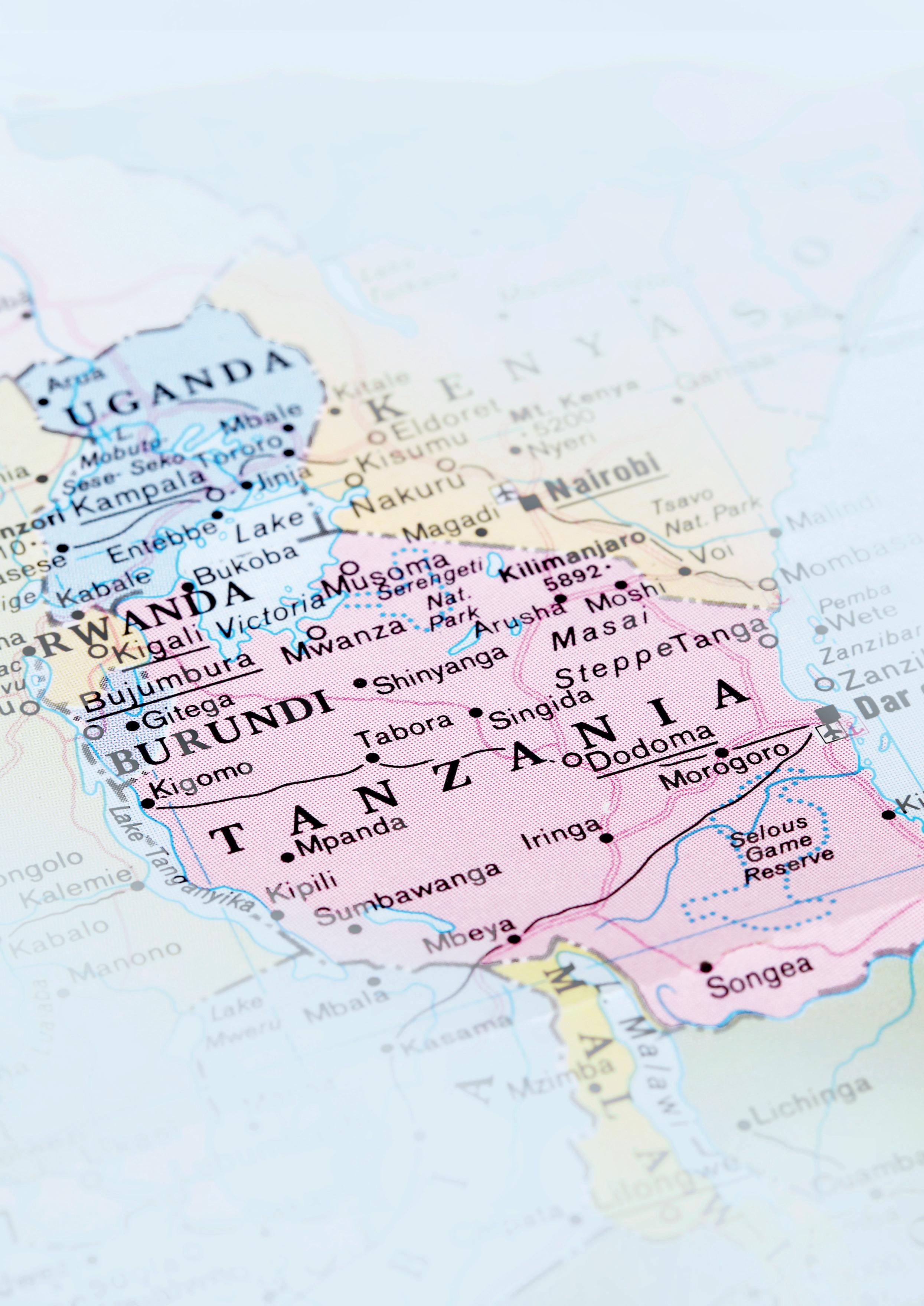
Kaikai Shu, ACIMEX, China, describes the company’s role in providing vacuum handling solutions for the groundbreaking EACOP project.
he East African Crude Oil Pipeline (EACOP) project stands as a landmark venture in East African energy cooperation, set to become the world’s longest heated crude oil pipeline. As a key equipment provider for this monumental project, ACIMEX has risen to meet unique challenges with innovative vacuum handling solutions that are proving crucial to the project’s progress. This article delves into the intricacies of the EACOP project, ACIMEX’s vital contributions, and the broader implications for the energy sector and regional development.
Project overview
The EACOP project represents a significant milestone in East Africa’s energy landscape. Aimed at transporting Uganda’s oil resources to Tanzania’s port, this ambitious pipeline will span an impressive 1443 km. The route begins in Kabale, located in Uganda’s Hoima District, and traverses both Uganda and Tanzania before terminating at Tanga Port on Tanzania’s Tangjongoleani Peninsula.
Key project details
) Total project investment: approximately US$3.5 billion.
) Pipeline length: 1443 km.
) Oil transportation capacity: 216 000 bpd.
) Expected completion: 2025.
The project brings together a diverse group of stakeholders, reflecting its international significance: Total Energy (72%), China National Offshore Oil Corporation Limited (8%), the Ugandan government (15%), and the Tanzanian government (5%).
The general contractor for this mammoth undertaking is China Petroleum Pipeline Bureau Engineering Co., Ltd., a subsidiary of China Petroleum Engineering Co., Ltd. Their contract is valued at approximately US$806 million, highlighting the scale and complexity of the project.
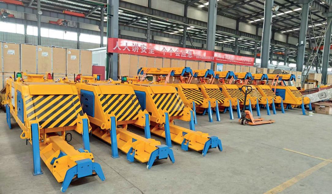
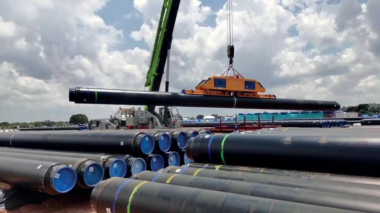
Meeting project challenges
In this groundbreaking project, ACIMEX has been entrusted to provide vacuum handling equipment. Our involvement addresses several key challenges inherent to this ambitious undertaking:
) Long-distance, outdoor construction: the project’s vast scale and outdoor nature present significant logistical and operational hurdles. ACIMEX’s equipment is designed to withstand diverse environmental conditions across the 1443 km route.
) Extended operational periods: given the project’s timeline and scale, equipment must function reliably over long durations in varying environmental conditions. This demands robust, durable solutions that can perform consistently in challenging settings.
) Stringent safety requirements: the scale and importance of the EACOP project necessitate paramount safety in all aspects of construction. ACIMEX’s equipment incorporates multiple safety features to meet and exceed these requirements.
) Precision in pipeline laying: accurate placement and adjustment of pipeline segments during installation are crucial for the project’s success and long-term operational efficiency.
Providing solutions
To address these challenges effectively, ACIMEX has deployed state-of-the-art vacuum handling equipment with several innovative features:
Self-powered diesel engine system
• Ensures long-term operation of vacuum equipment without reliance on external power sources.
• Crucial for remote areas along the pipeline route where access to consistent power supply may be limited.
• Enhances operational flexibility and reduces downtime.
Enhanced design and protection
• Equipment surpasses the stringent requirements set by China Petroleum Pipeline Engineering Co., Ltd.
• Ensures durability and reliability in challenging environments, including extreme temperatures and dusty conditions.
Multiple safety release systems
• Incorporates various fail-safes to guarantee construction safety.
• Includes emergency shut-off mechanisms, load monitoring systems, and redundant safety features.
• Ensures operator safety and protects valuable pipeline components during handling.
Hydraulic system for excavator-mounted equipment
• Allows for precise rotational adjustment of pipes during laying.
• Significantly enhances on-site construction efficiency and application flexibility.
• Enables operators to make minute adjustments, ensuring perfect alignment of pipeline segments.

ABC. See it. Believe it. Trust it. To advertise email Chris Lethbridge at chris.lethbridge@worldpipelines.com or Daniel Farr at daniel.farr@worldpipelines.com
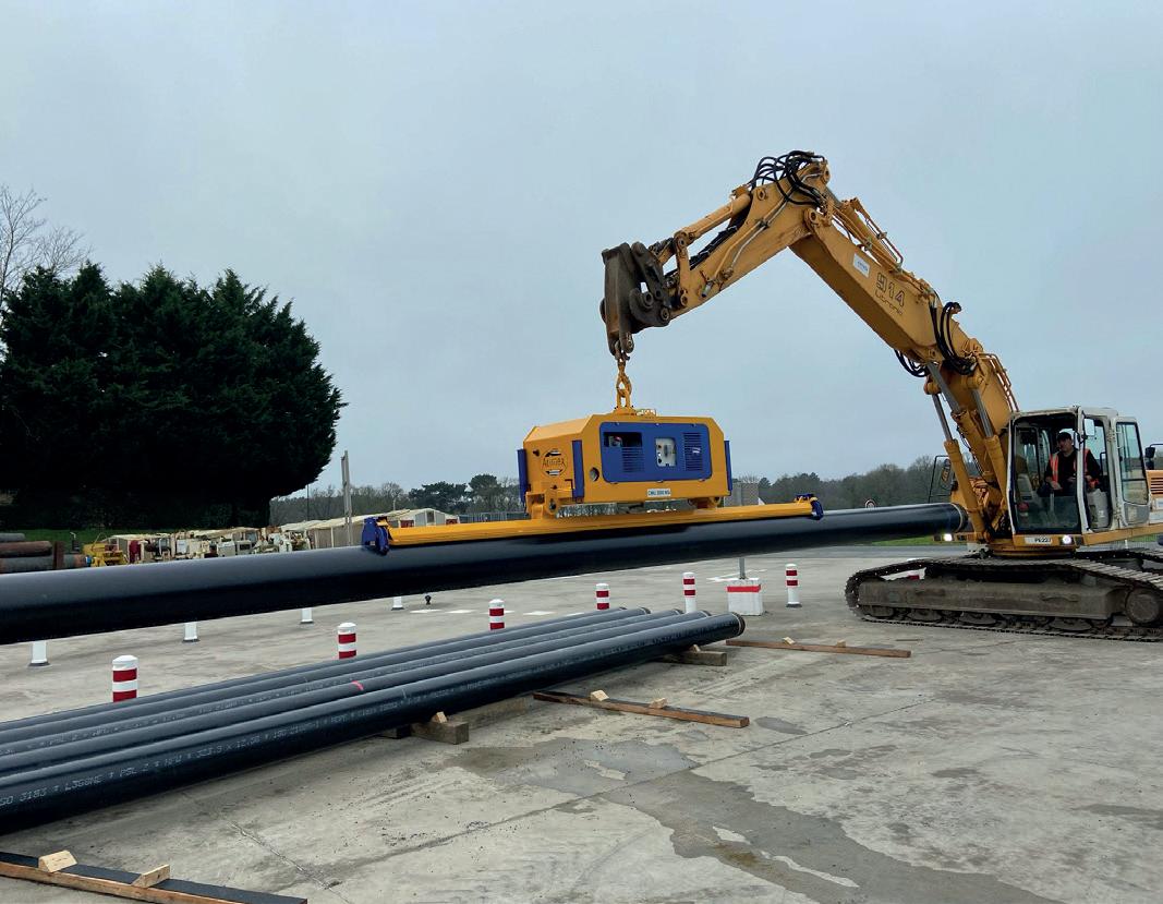
To provide a deeper understanding of ACIMEX’s contributions, here are some key technical specifications of the vacuum handling equipment deployed in the EACOP project:
) Lifting capacity: up to 25 t, capable of handling the largest pipeline used in the project.
) Paint and treatment adapted to arid conditions.
) Power source: self-powered diesel engine system, can be hydraulic or thermic depending on needs.
) Control system: controlled from the cab using the excavator’s joystick and an ACIMEX remote control for pick-up/drop-off.
China Petroleum Pipeline Engineering Co., Ltd. has strategically invested in a total of 23 sets of ACIMEX vacuum handling equipment for the EACOP project. 15 sets are dedicated to on-site pipe transfer and loading/unloading operations with truck cranes, eight sets are specifically designed for pipelaying and construction activities with excavators.
This distribution ensures efficient handling of pipeline segments at various stages of the construction process, from transportation to final installation.
As of October 2024, significant progress has been made in equipment delivery. 15 sets have been successfully delivered by ACIMEX China, and the remaining eight sets are on their way to Africa (transport by ship).
The complete array of 23 ACIMEX vacuum handling units is expected to arrive at the construction bases in Uganda and Tanzania by the end of October, ready to contribute to the EACOP project’s construction phase.
The selection of ACIMEX equipment for the EACOP project underscores the company’s global reputation in the industrial
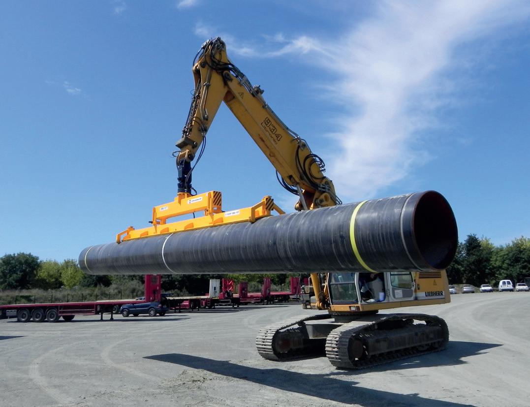
field. This prestigious project serves as a testament to ACIMEX’s expertise in providing specialised handling solutions for large-scale infrastructure developments.
ACIMEX’s vacuum handling solutions are trusted by customers worldwide, with major players in the Chinese market prioritising ACIMEX equipment for critical projects. This trust is built on a foundation of consistent product quality, innovative technological solutions, reliable after-sales support, and adaptability to diverse project requirements.
This successful partnership paves the way for future collaborations on overseas projects, further cementing ACIMEX’s position as a leader in specialised handling equipment for large-scale infrastructure projects.
ACIMEX’s involvement in the EACOP project showcases its technological leadership in several key areas:
• Vacuum technology advancements: development of highefficiency, reliable vacuum systems capable of operating in challenging environments.
• Customisation capabilities: ability to tailor solutions to specific project requirements, demonstrating flexibility and engineering prowess.
• Safety innovations: continual improvement in safety features, setting new standards in the industry.
As the EACOP project progresses, ACIMEX remains committed to supporting this vital energy infrastructure development. The company’s involvement in this project not only showcases its technical capabilities but also positions it at the forefront of innovation in pipeline construction equipment.
The successful implementation of our vacuum handling solutions in the EACOP project serves as a testament to ACIMEX’s ability to meet complex challenges in large-scale energy projects. With our proven track record in the EACOP project and our ongoing commitment to innovation, ACIMEX is poised to play an increasingly significant role in shaping the future of pipeline construction and energy infrastructure development worldwide.
Dr James Dean, CEO, Plastometrex, details the growing importance of accurate material verification in ensuring the safety and integrity of pipelines, a critical component of pipeline management in light of recent regulations.

ccurate verification of pipeline material properties is essential for ensuring the integrity of North America’s oil and gas transmission pipelines. Its importance is underscored by United States Pipeline and Hazardous Materials Safety Administration’s (PHMSA) recent Mega Rule legislation, which mandates testing of undocumented pipelines for
reconfirmation of maximum allowable operating pressure (MAOP). Given that MAOP is dependent upon the grade of metal used, which can often be determined from accurate determination of yield stress (among other characteristics), material verification has become an increasingly important component in the integrity management programmes of pipeline owners and operators.
Accurate grade determination is no trivial matter. Mechanical properties, including yield stress and tensile strength, alongside other datasets such as chemical composition, microstructural features, and historical operating conditions, can help provide a good, but not necessarily perfect, determination of a pipe’s grade. Uncertainty can arise from a multitude of angles, including overlapping material properties for various pipe grades, operational error at the point of data collection, or system inaccuracies. This is why operators are mandated by legislation, such as the Mega Rule, to proceed with caution when determining pipe grade. This more conservative approach may lead to a reduced operating pressure and a reduced volume flowrate, but prioritises asset integrity. That, of course, should be the position, since the consequences of misidentifying pipeline grade can be farreaching and devastating.
The risks of compromising pipeline safety are multifaceted, encompassing economic, environmental and safety concerns. For operators, a pipeline failure can result in substantial financial losses, not only due to the high cost of repairs and product loss, but also because of government fines, legal liabilities, and the long-term reputational damage a company may suffer. These incidents can lead to a loss of investor confidence, causing stock prices to plummet and plunging companies into financial freefall.
Pipeline failures can also have consequences for both the environment and human populations that live near affected areas. Oil or gas spills may severely pollute bodies of water and the surrounding soil, disrupting natural ecosystems and causing long-term harm to wildlife. Pipeline explosions or leaks pose significant risks to nearby communities, leading to injuries or, in the most severe cases, even death. The release of hazardous substances can also cause long-term health problems for those exposed either directly or indirectly due to water and soil contamination. Cleanup efforts are often expensive and time-intensive and may not be able to reverse all of these consequences. For operators and inspection companies, these risks underscore the critical importance of accurate material verification and grade determination.
For these reasons, regulations that enhance pipeline safety should be supported. Frameworks like the Mega Rule legislation, which covers material verification, place the onus on owners and operators to ensure that the tools used for yield stress determination are technically defensible. These tools must undergo rigorous review, testing, and validation by subject-matter experts to ensure they meet the industry standard for accuracy and reliability. Such validation programmes are essential for ensuring technical defensibility and for comparing the accuracy of competing tools, upholding the industry standard for accurate data to support grade identification.
Despite this, findings still show that some material verification testing technologies can misjudge pipe strength by more than 25%, which could severely skew grade determination calculations and have a significant impact on pipeline integrity efforts. Sub-standard accuracy should not be tolerated when the safety and integrity of critical national
infrastructure is at risk. This is something that owners, operators, and the providers of material verification services ought to be aligned on.
One key component of the Mega Rule legislation is MAOP reconfirmation – or calculation of the maximum allowable operating pressure. The calculation is straightforward, requiring a few simple input parameters, including a specified minimum yield stress (SMYS). The value of SMYS that is used in these calculations is fixed and is dependent on the grade of the pipe, with common grades including X42 (SMYS = 42 ksi), X52 (SMYS = 52 ksi), and X70 (SMYS = 70 ksi), among others. However, it’s important to note that the actual yield stress of a pipe rarely matches the nominal SMYS value exactly. For example, while X42 pipe is associated with a SMYS of 42 ksi, the actual yield stress may vary due to manufacturing inconsistencies.
As an example, if a tool inaccurately measures a yield stress of 66 ksi, it would be reasonable to assume that the pipe grade is X65, when in fact an accurate measurement would show a yield stress to be 53 ksi, which would support an X52 call on grade, leading to this number being used in the MAOP calculation. If X65 was wrongly assumed, the resulting MAOP calculation could be dangerously overestimated, leading to the potentially devastating consequences discussed above. This is a key reason why accurate material verification is essential to grade identification and, by extension, pipeline safety.
Several approaches are available for in-situ material verification of metal pipelines, each with a distinct method for determining material properties. These methods include estimating yield and tensile strength from load-displacement data; analysing a material’s response to plastic deformation caused by creating grooves across the pipe surface; and combining hardness testing with chemical analysis and microstructural examination. The most recent advancement in this field, known as Profilometry-based Indentation Plastometry (PIP), involves measuring the full profile of an indent, rather than just its depth. This method leverages sophisticated software that compares the full shape of the indent with the outcome of a finite element simulation of the indentation test.
Given the critical importance of accuracy in material verification, stakeholders in the midstream oil and gas industry have been evaluating the accuracy of material verification tools through head-to-head round-robin studies. These studies are an excellent mechanism for ensuring that the tools are technically defensible, as required by the Mega Rule legislation.
In June of 2024, the results from a highly-anticipated independent round-robin were published. This study was commissioned and overseen by the Pipeline Research Council International (PRCI), Blade Energy, and TC Energy, with additional support from other leading operators and
January 27-31 • Houston

The industry’s only forum devoted exclusively to pipeline pigging for maintenance and inspection
This event will draw engineering management and field operating personnel from both transmission and distribution companies concerned with improved operations and integrity management.
Technical papers will cover ILI data assessment, prioritization of repairs, new tools, improving tool performance, external coating inspection with ILI tools, pig launch and receiving systems, new regulations and much more.
Visit one-on-one with the world’s top providers of pigging, ILI, and integrity management services – over 170 companies will be represented.
13 in-depth, technical pipeline training courses will be held prior to the conference and exhibition. Upskill your workforce for 2025.


engineering companies. The project was focused specifically on seamless pipe and fittings. Four competing tools were tested, and the PLX-Portable, employing the PIP testing method, by Plastometrex emerged as the clear leader, setting a new industry standard with a 3.6% MAPE on yield stress for seamless pipe. This degree of accuracy is particularly important for ensuring safe grade determination, especially when compared to other solutions in the market that consistently fall short of this standard.
Another study was conducted in 2018, also via the PRCI, in which 50 samples of pipe, covering all the common grades, were blind tested by competing tools and methods. A ‘winner’ emerged, albeit only marginally, with a winning MAPE number of 7.0% on yield stress and 4.4% on tensile strength. In 2023, the PLX-Portable was granted access to the same set of samples that were tested in the 2018 round-robin. Independent reviews by RSI Pipeline Solutions LLC, confirmed that the PLX-Portable had the lowest MAPE number at 5.3% for yield stress and 3.6% for tensile strength, outperforming all previously tested methods. In addition, the PLX-Portable had the lowest maximum overprediction, and the highest proportion of all test results falling within ± 10% and ± 15% of destructive tensile test results.
The findings from both the 2024 and 2018 independent round-robins confirm PIP testing as the most accurate method for determining the mechanical properties of pipelines. The PIP technique stands out because it not only measures the depth of the indentation but also the entire profile, which provides a more comprehensive understanding of the material’s behaviour under stress. This high level of accuracy is essential for correctly identifying the grade of pipeline materials and ensuring safe and reliable operations.
Built around this underlying PIP methodology, the PLX-Portable is a non-destructive mechanical test device
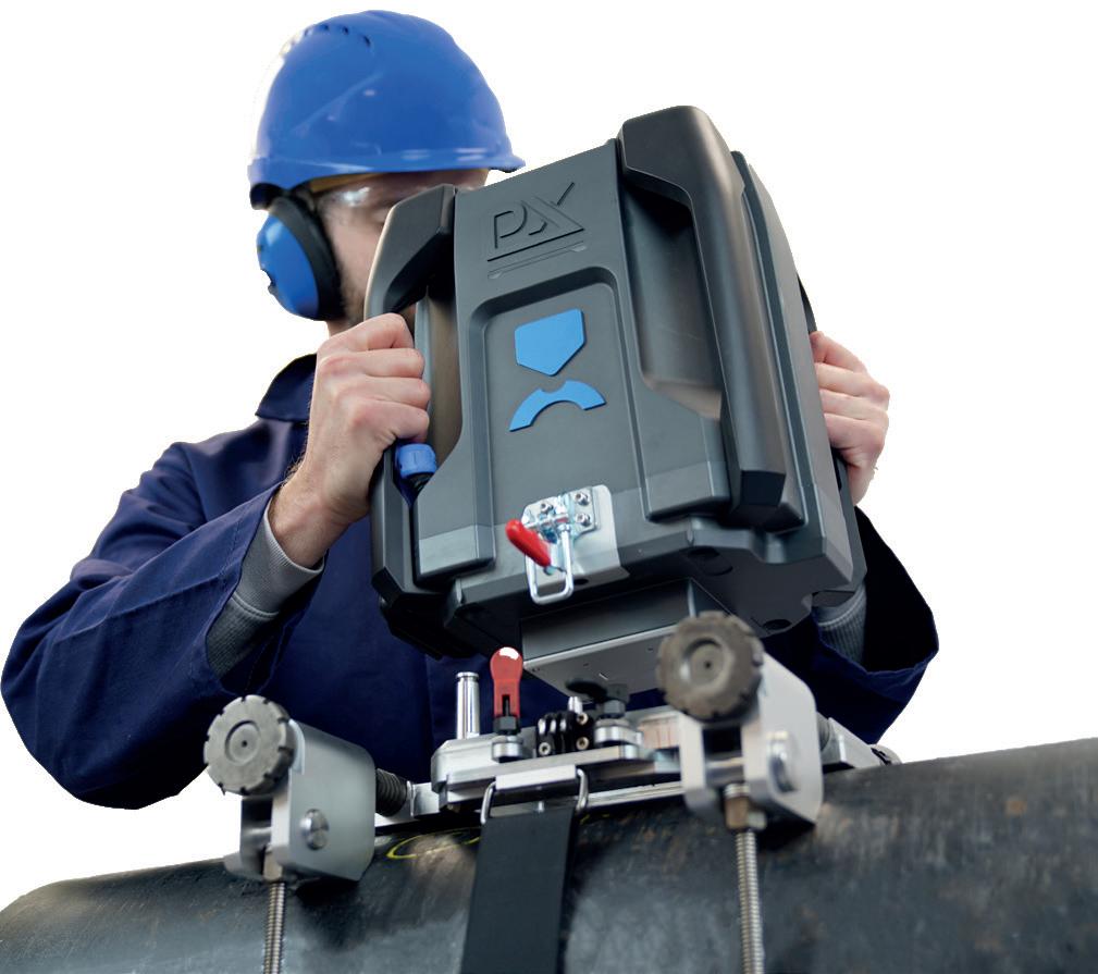
that attaches to metal pipelines and measures their yield and tensile strength. This device is derived from the company’s flagship product, the PLX-Benchtop, which is a lab-based mechanical testing device that measures the stress-strain behaviour of metallic materials using a quick and simple indentation test. The PLX-Benchtop has been globally adopted by industry leaders in aerospace, defence, automotive, energy, and manufacturing, as well as some of the world’s most prestigious universities.
The technical specifications for the PLX-Portable were developed in consultation with leading asset integrity service providers and operators, including ROSEN, Mistras, Acuren, DNV, RSI Pipeline Solutions, TC Energy, and Element Materials Technology. Across the board, accuracy was a primary requirement in these consultations. In addition, the system had to be quick and simple to deploy, with final and definitive test results available immediately in the ditch. Training also had to be simple and scalable, to support Mega Rule testing demand.
The PLX-Portable delivers on all of these fronts and has been described as being ‘technician agnostic,’ meaning that the results are consistent regardless of which technician operates the device. This consistency is due to the intuitive, software-driven user workflows and the built-in checks and balances that monitor data integrity. All test results are stored in PLXUS, an online digital platform built by Plastometrex, in a regulatory-compliant format.
Confidence is the cornerstone of effective integrity management programmes. For pipeline owners and operators, confidence in the data they rely on is nonnegotiable. The accuracy and reliability of material verification tools directly influence the decisions made regarding pipeline operation, maintenance, and safety. When tools like the PLX-Portable deliver reliable and repeatable results, operators can make informed decisions that enhance the safety and longevity of their assets.
The importance of confidence in integrity management extends beyond immediate inspections. It fosters a culture of proactive management, where potential issues are identified and addressed before they escalate into serious problems. Furthermore, this confidence bolsters the relationship between operators and stakeholders, including regulators, investors, and the public.
The integration of highly accurate and reliable material verification tools like the PLX-Portable into integrity management programmes is essential for building and maintaining confidence at every level. From in-ditch inspections to long-term asset management, this is what ultimately drives better decision-making, enhances pipeline safety, and ensures the ongoing integrity of this critical infrastructure. As the industry continues to evolve and face new challenges, the role of accurate and reliable material verification technology will only become more central to the success of integrity management programmes.
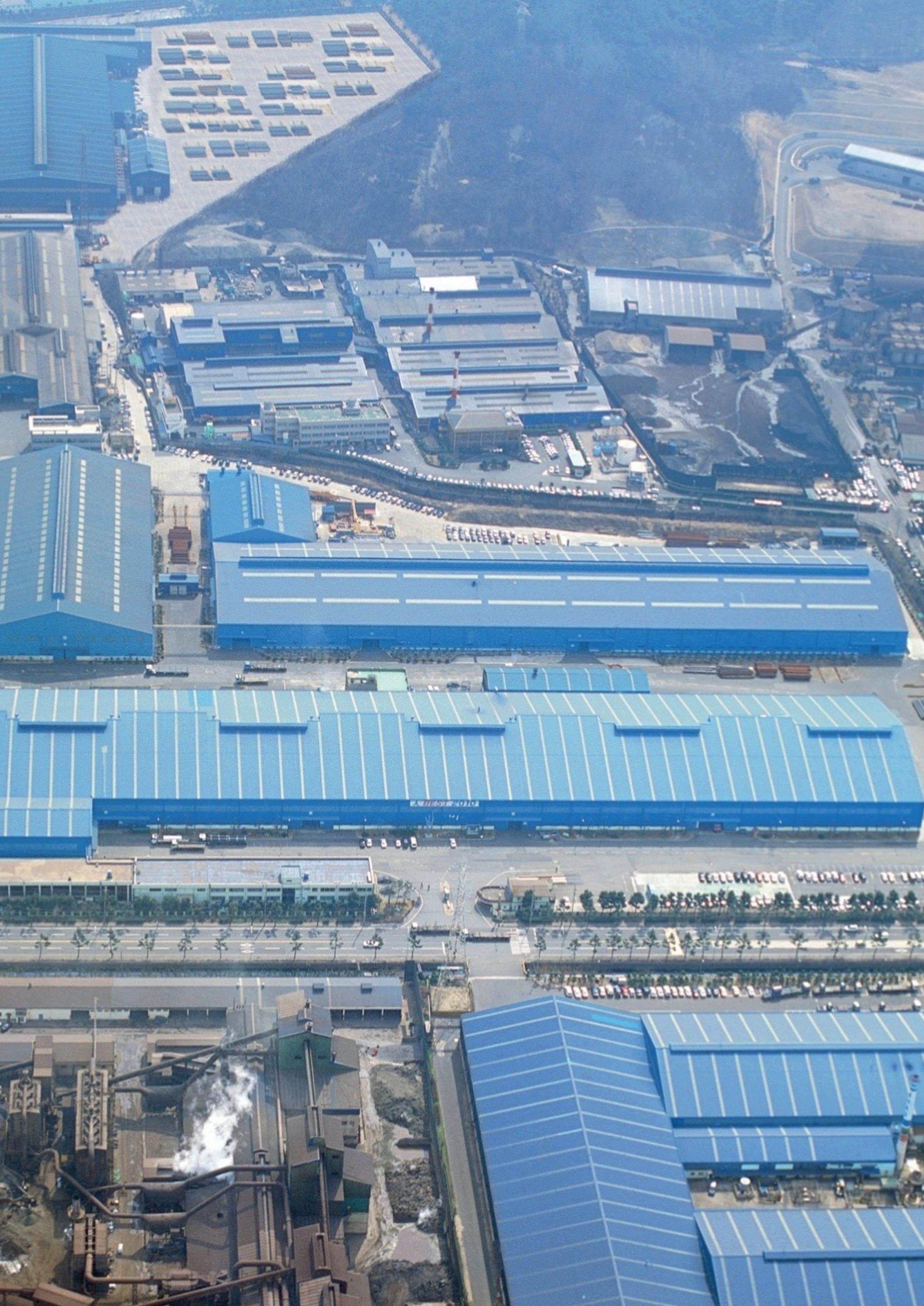
Minchan Jung, Materials Engineer, SeAH, South Korea, discusses the development of high-pressure hydrogen transport pipes for stable, large-scale hydrogen transportation.
n line with carbon neutrality policies, the demand for hydrogen, an ecofriendly energy source, is gradually increasing. According to the Global Hydrogen Review 2023 published by the IEA, the global demand for hydrogen, which was around 90 million t in 2020, is expected to reach 150 million t by 2030. It is estimated that the total length of steel pipes currently used worldwide for hydrogen transportation exceeds 4500 km. In this social context, the development of high-pressure hydrogen transport pipes for stable, large-scale
transportation of hydrogen is an essential technology for an eco-friendly society.
Characteristics of steel pipes for hydrogen transport
High-pressure hydrogen induces hydrogen embrittlement in steel. Hydrogen embrittlement refers to the tendency of metal materials to lose ductility and toughness and even fracture without plastic deformation due to absorbed hydrogen. As the smallest element, hydrogen can easily penetrate the crystal structure of metals.
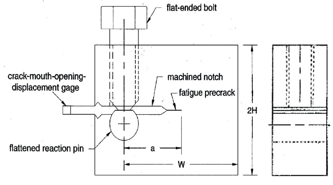
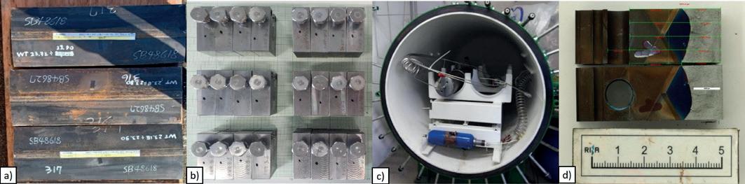
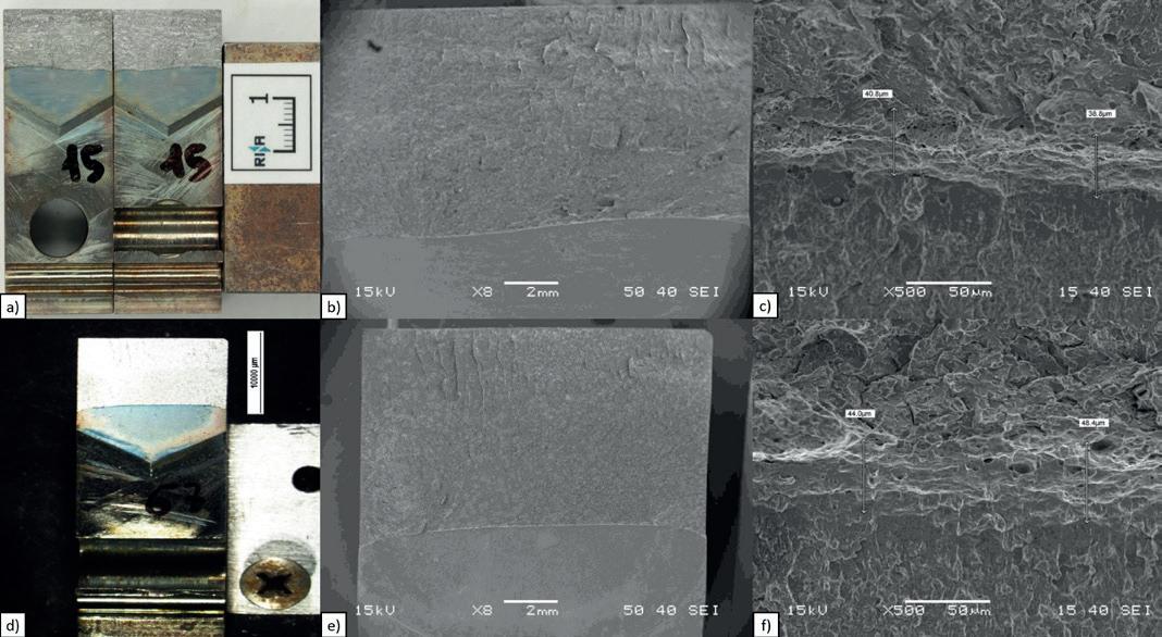
The hydrogen atoms infiltrating the metal crystal not only disperse among the structures but also accumulate in spaces such as dislocations, vacancies, and grain boundaries within the metal. The accumulated hydrogen obstructs the deformation of the metal, leading to embrittlement. Therefore, hydrogen embrittlement resistance is a critical factor for carbon steel pipes that transport high-pressure hydrogen. Various methods exist to evaluate resistance to hydrogen embrittlement, and K1H a representative indicator used to assess hydrogen embrittlement resistance is one of the essential properties required for quality evaluation of hydrogen pipelines.
SeAH Steel applied Seam QT heat treatment and JCO forming optimisation technologies to ensure the stable quality of hydrogen transport pipes. We produced API 5L
X70M PSL2 O.D 508 mm x W.T 15.9 mm ERW and API 5L
X70M PSL2 O.D 762 mm x W.T 23.0 mm SAW pipes in three heats each.
) Seam QT heat treatment technology: This technology involves performing quenching and tempering heat treatment after ERW welding to enhance the stability of the welded structure. The weld zone of ERW steel pipes tends to be less stable compared to the base metal, but by applying Seam QT heat treatment, the quality of the weld zone was secured to a level similar to that of the base metal.
) JCO forming optimisation technology: This technology monitors the JCO press forming shape in real-time through a monitoring device and derives the optimal forming conditions. By stabilising the forming shape, which can act as a variable during SAW welding, uniform SAW welding quality is ensured.
Hydrogen embrittlement resistance evaluation criteria

SeAH Steel conducted the K 1H hydrogen embrittlement resistance evaluation through RINA Consulting – Centro Sviluppo Materiali S.p.A (CSM), an expert institution in hydrogen embrittlement evaluation. This test was conducted to evaluate whether the pipes produced by SeAH Steel meet the hydrogen embrittlement resistance required for hydrogen transport pipes through crack resistance qualification. The test was conducted based on ASME B31.12, Section PL-3.7.1 Steel Piping Systems Design, Option B (PerformanceBased Design Method), ASME BPVC Article KD-10, and ASTM E1681, applying 80 bar of 100% H 2 gas for 1000 hours.


Subscribe online at: www.oilfieldtechnology.com/subscribe

) ASME B31.12, Section PL-3.7.1, Option B: This section specifies the test location, specimen orientation, and minimum K1H requirements. Tests must be conducted on the base, weld, and HAZ in three heats, with the required K1H being a minimum of 55 MPa•√m.
) ASME BPVC Article KD-10: This article provides guidelines zfor the test process. Specimen shape follows ASTM.
) E1681, and the specimen thickness must be at least 85% of the pipe thickness. The test methods include the constant load method and constant displacement method, depending on the load application method. The hydrogen gas purity should be 99.9999% or higher, and the test duration must be at least 1000 hours. After the test, the average crack growth at t/4, t/2, and 3t/4 positions is calculated, and if this value is 0.25 mm or less, the K 1H value is calculated. The method of calculating the K 1H value varies depending on the test method: in the constant load method, the test load is taken as the K 1H value, and in the constant displacement method, 50% of the test load is taken as the K 1H value.
) ASTM E1681: This standard specifies the criteria for specimen processing, shape suitability, and pre-cracking conditions. In this test, the constant displacement method was applied, and a bolt-load compact specimen was used.
The test results showed that crack growth due to hydrogen was less than 0.25 mm, with no additional anomalies observed. The calculated K 1H values were Weld >74.1 MPa•√m, HAZ >79.6 MPa•√m, and Base >74.7 MPa•√m, all of which met the minimum requirement of Min. 55 MPa•√m as specified in ASME B31.12, confirming that the pipes possess excellent hydrogen embrittlement resistance required for hydrogen transport pipes.
In line with the global expansion of the hydrogen market, SeAH Steel has conducted reliable evaluations of the quality level of hydrogen transport pipes, and has supplied 7 km of pipes for the Ansan Hydrogen City Project and 4.5 km for the POSCO Plantec Hydrogen Project in South Korea. Moving forward, SeAH Steel plans to continue developing high-quality hydrogen transport pipes, establishing a foundation for entering the global hydrogen pipeline market, including Europe and the Americas, while also contributing to urban construction projects.