9 minute read
Explaining reciprocating pumps


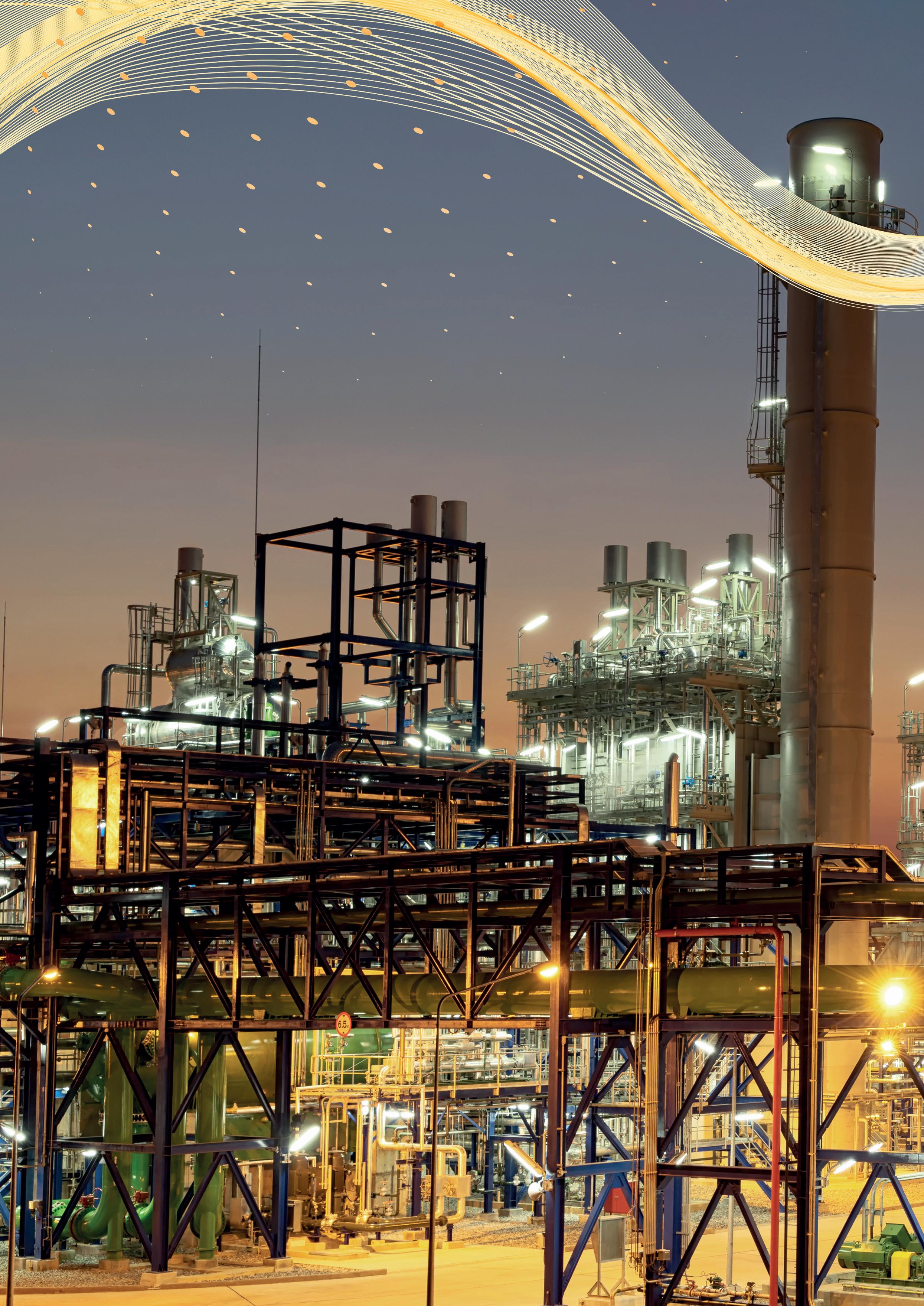
Figure 1. Reciprocating pumps bring benefits in critical flow control applications where high differential pressure is combined with relatively low flowrates.
Jeff Ortego and Alan Matthews, Celeros Flow Technology, US, explain how and when to deploy reciprocating pumps to deliver better efficiency and reduce total cost of ownership.
Reciprocating pumps offer many benefits in low flow, high pressure applications commonly found in the oil and gas sector. However, the technology is not as well understood as centrifugal pumps, which can lead to mis-specification. Every process condition needs a pump. The challenge facing pump specifiers and users is to identify the technology that will best meet the

application criteria. Commonly, such criteria will comprise efficiency, reliability and environmental impacts – including energy consumption – and regulatory requirements. The pump also has to comply with time and budget constraints. These are not limited to capital costs and installation time; the total cost of ownership and the frequency and length of essential maintenance outages are also an important consideration.
In the majority of standard duty applications, centrifugal pump technology is deployed. This technology is widely understood, proven in the field and generally reliable. However, it is not always easily scalable, and can sometimes become prohibitively expensive. Centrifugal pumps also experience poorer performance above certain viscosities and experience high erosion rates in services with entrained solids, which is where a reciprocating pump can provide a better alternative.
Reciprocal pumps are particularly suited to critical flow control applications where high differential pressure is combined with relatively low flowrates. Examples include systems for wash water, butane injection, glycol services, amine services, high pressure chemical injection, and hot oil catalyst transport. In these circumstances, reciprocating pump technology can provide a better and more efficient solution, with benefits including: ) Lower erosion rates than centrifugal technology due to lower speeds.
) Simplicity of deployment.
) High efficiency (90% reciprocating vs 50% centrifugal).
) Near-zero emissions, when correctly applied and maintained.
However, lack of familiarity with the mechanism and the need to take an entire system approach to the flow control design can prove a barrier to deployment. In this article, we will explore the technical differences between the two pump technologies and explain the simple steps that can be taken to optimise reciprocating pump performance. Operating principles There are fundamental differences in the way centrifugal and reciprocating pumps operate. It is important to understand the basic principles in order to appreciate the benefits and disbenefits of each technology.
Centrifugal (kinetic) pumps work by the conversion of rotational kinetic energy, typically from an electric motor or a turbine, to create a static fluid pressure. Flow velocity is increased in the impeller and this energy is subsequently converted to static pressure due to change in the flow area in the volute section.
Reciprocating pumps use the positive displacement method. Here, liquid is displaced, delivered, or discharged at a fixed rate per revolution of the pump. This displacement rate is dependent upon the plunger diameters, the stroke length, and the number of plungers used. A reciprocating pump is therefore a device that moves a plunger or plungers, creating a moving boundary in the pumping. Check valves ensure the direction of flow is maintained from suction to discharge during the operations of the pump changer. The reciprocating motion generated by use of the crank and the slider mechanism in the pump causes the liquid to be moved and energised from suction to discharge.
One of the benefits of reciprocating pumps is that precise capacity can be achieved with a fixed volume of fluid because the flowrate (or flowrate generation) is linearly proportional to the speed. As a result, variable capacity is achieved by changing pump speed, while the pressure on the discharge side of the system is set by the system itself. This means we can generate near constant flow regardless of pressure to match process performance.
An important distinction here is that a centrifugal pump has varying flow and varying head, resulting in a curvilinear response instead of a rectilinear response.
Following best practice As we intimated in the introduction, when it comes to correct pump specification, it’s not just about the pump. Although a vital piece of equipment, the pump needs to be considered as part of the wider system in order to achieve optimal results.
API 674 gives best practice guidelines for the correct specification of positive displacement pumps, including crankshaft-driven power pumps and direct-acting pumps driven by steam or other gases.
These guidelines require reliable operation in a wide variety of services and conditions. There are speed limits imposed based on the stroke length of the machine: these speed limits are in place to reduce the potential for piping vibration in the wider system; left unchecked those vibrations can produce water hammer, piping failures, etc. The pulsations produced by reciprocating pumps are typically also controlled by use of adequately specified pulsation equipment which reduces the magnitude (amplitude) of pulsations.
Capital costs can be greatly reduced through use of adequate pulsation equipment and pump sizing optimisation. Changing flowrates can be accomplished by changing plunger diameters to increase or decrease displaced volume at a given speed. The speed can also be varied however, providing a
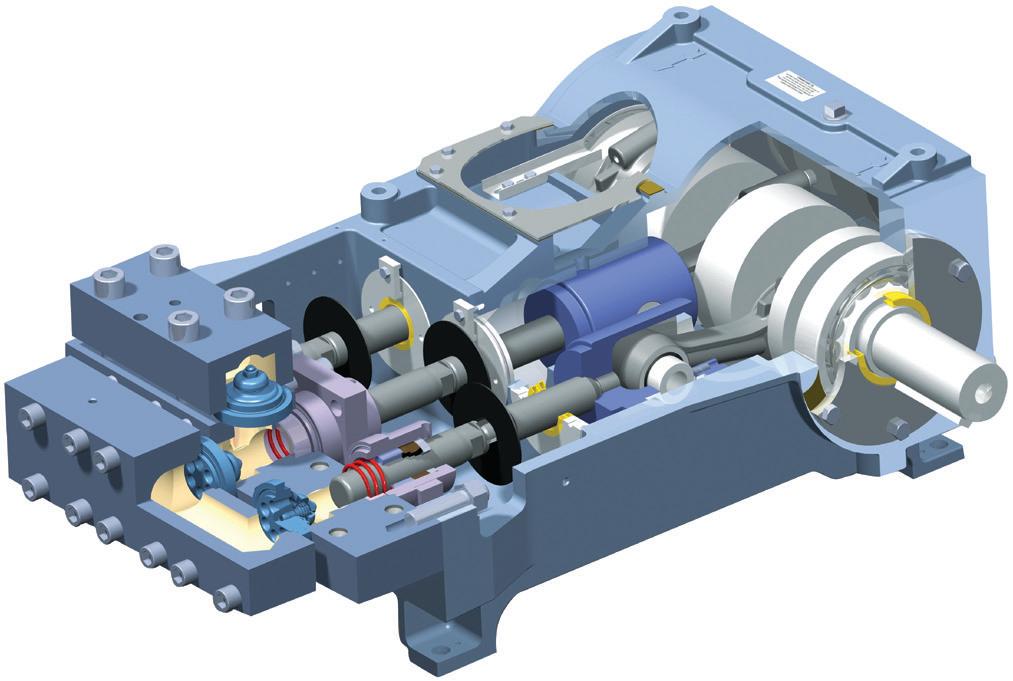
Figure 2. A reciprocating pump is essentially a device that moves a plunger or plungers in and out of the liquid.


wide operating range for a given pump. Maintenance typically consists of checks for packing leakage, but leakages can be greatly minimised, reduced, or completely controlled to mitigate release of the pumped fluid(s) to the environment.
Design specifications and installing the ‘right’ pump can make all the difference between a successful and reliable installation and a costly installation with poor performance. Here’s where we need to understand some acronyms. MAWP is the maximum allowable working pressure of the fluid allowed within the pump. NPSH is net positive suction head, which is a quantity that can be available in the system (NPSHA) and also a quantity that can be required by the pump for reliable operation (NPSHR).
NPSH is typically used in the specification and calculation of centrifugal pumps. When dealing with positive displacement pumps, however, we are actually interested in net positive inlet pressure (NPIPA and NPIPR). These criteria are more adequate descriptions of what is available and what is required in terms of how the pump physically operates – particularly with regard to the operation of the suction valves.
Design solutions Concerns around reciprocating pump technology include premature fatigue failure, noise and vibration (e.g. water hammer) in connected pipework. These phenomena can be caused by excessive speed on a reciprocating pump, which produces higher and higher frequencies within the piping surrounding it. Although difficult to control post-installation, it is readily achievable to design out the potential for such issues.
In addition to adhering to the speed ratings laid down in API 674, pulsation reduction equipment can be installed to control pulsations. Typically, these solutions are referred to as discharge dampeners and suction stabilisers.
The discharge dampener is responsible for reducing the potential for fatigue failures and mechanical vibrations from the discharge side of the system. With reciprocating pumps, there is commonly a low suction pressure entering the pump and a very high discharge pressure, typically of several thousand PSI. This high working pressure means there is a whole lot of energy available to produce damage if things go wrong. The discharge dampener greatly reduces the amount of pulsation in the piping.
On the suction side of the system the installation of a suction stabiliser is recommended to reduce the amount of acceleration head experienced by the pump in the system. This has the effect of helping to provide the best suction performance of the pump by reducing the amount of acceleration head loss, relative to what the static head is in the system. It also helps reduce phenomena like water hammer and the generation of vapour pockets.
Resolving post installation issues Of course, ideal conditions are difficult to achieve in real industrial applications, but in our experience the root cause of an issue is generally not the reciprocating pump technology itself. For example, on one application that Celeros Flow Technology (Celeros FT) was called in to investigate, a reciprocating pump was causing unacceptable downtime issues for a downstream oil and gas operation. Frequent valve spring failures were resulting in a pump shut down every two to three weeks, leading to frequent maintenance interventions and the associated costs.
The reciprocating pumps in question had been installed originally to replace smaller wash water pumps with no modification to the piping. At the time of sale, the customer had been made aware that the piping system was undersized and that reliability would be compromised. The pumps had a long history of breaking suction and discharge valves, until a modified valve design was proposed and installed. The remaining reliability issues focused around packing and valve springs.
Celeros FT conducted a site investigation to determine the cause of the frequent valve spring failures. Springs were analysed for the type of failure, repeatability of failure, and conclusions drawn regarding the cause. Analysis revealed that a fatigue failure was occurring in an area of the spring where the pitch was changed to close and grind the ends during manufacture. Surface defects in this area were produced during this pitch change, resulting in stress risers that led to a premature fatigue failure which was not displayed in other installations of the same pump model.
Solving the issue was reasonably straightforward. The existing valve spring design, material and manufacturing process was unchanged – with the exception that the completed valve springs were shot peened. This additional process mitigated the stress concentration at the surface of the spring wire produced during manufacture. Upgraded valve springs were installed at the site and the failures stopped occurring.
Tracing the cause of valve spring failure back to the point of system interaction with the pump resulted in a manufacturing improvement that restored the reliability of the reciprocating pumps. Frequent downtime is a thing of the past and maintenance costs have been greatly reduced. In this manner, Celeros FT was able to tailor component design within the pump to mitigate the issues caused by poor system design and inadequate pulsation control.
Conclusion Reciprocating pumps have much to offer in terms of improved performance, efficiency and energy consumption, particularly in low flow, high pressure differential applications where centrifugal pump technology is uneconomic due to scale or ineffective due to the process liquid viscosity.
However, proper sizing of a reciprocating pump can greatly affect the operating parameters of the machine. Several sealing arrangements can be configured based on process fluid, lubrication requirements and environmental leakage concerns. Power frame and fluid cylinder ratings are independent values from each other, but neither should be exceeded during operation. Also, pulsation equipment and the piping system around the reciprocating pump can have a large effect on long term reliability of the system.
There is a wealth of information and guidance available to help specifiers feel confident in deploying this technology effectively, ranging from API 674 to support from individual equipment manufacturers. Celeros FT has recently revised its reciprocating pumps portfolio to align it with current market conditions, reducing design complexity and making it simpler to match the pump to the application.


