

03. Editor's comment
05. Pipeline news
Global pipeline updates, and contract news.
KEYNOTE: CCS PIPELINES
08. Skylark takes flight
Hari Vamadevan, Senior Vice President and Regional Director, UK and Ireland, Energy Systems, DNV.
13. Enabling the next wave of CCUS growth
Algert Prifti, CCUS Solutions Portfolio Manager, Black & Veatch. PIPELINE CONSTRUCTION
16. Boundary conditions across the pipeline lifecycle
Dr. Awadh O. Al-Oadah, Director Projects, Pipeline Projects Department, Saudi Aramco.
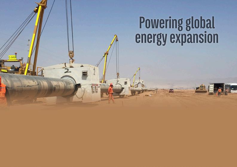
24. Powering global energy expansion
Paul McShane, President EMEAA at CRC Evans.
HEAVY EQUIPMENT
31. A safer future for pipeline construction
Etienne P., SCAIP S.p.A.
35. Redefining pipeline backfilling
Maimee Henderson, ALLU, USA.
PIG LAUNCHERS AND TRAPS
39. Barrel traps vs pigging valves
Nicolaas Ainsworth, Argus Machine Co. Ltd.
PRE-COMMISSIONING AND PIGGING SERVICES
45. Pressure testing in the modern era
Joe Van Vynckt, CEO, Charps.
HOT TAPPING AND LINE STOPPING
49. Life's simple joys
Matthew Guest and Ian Littlepage, Team, Inc.
53. Eliminating risks within pipeline systems
Fernando Arce-Larreta, Iron Gate Supply President and BridgeFlow Valve Partner.
59. Under pressure
Gary Burns, Technical Director, BEL Valves, UK.
INTEGRITY AND INSPECTION
65. A year of right-sized integrity management
Cassandra K. Moody and Chelsea La Salle, Time For Change Engineering, USA.
COATINGS AND LININGS
71. Eliminating hidden risks
Neil Wilds, Global Product Director of CUI/Testing, Sherwin-Williams Protective and Marine Coatings.
AUTOMATION
74. AI: the key to automating critical industries
Jackie Hu, Chief Operating Officer, and Michael Smith, Director, Data & AI, IMI plc.
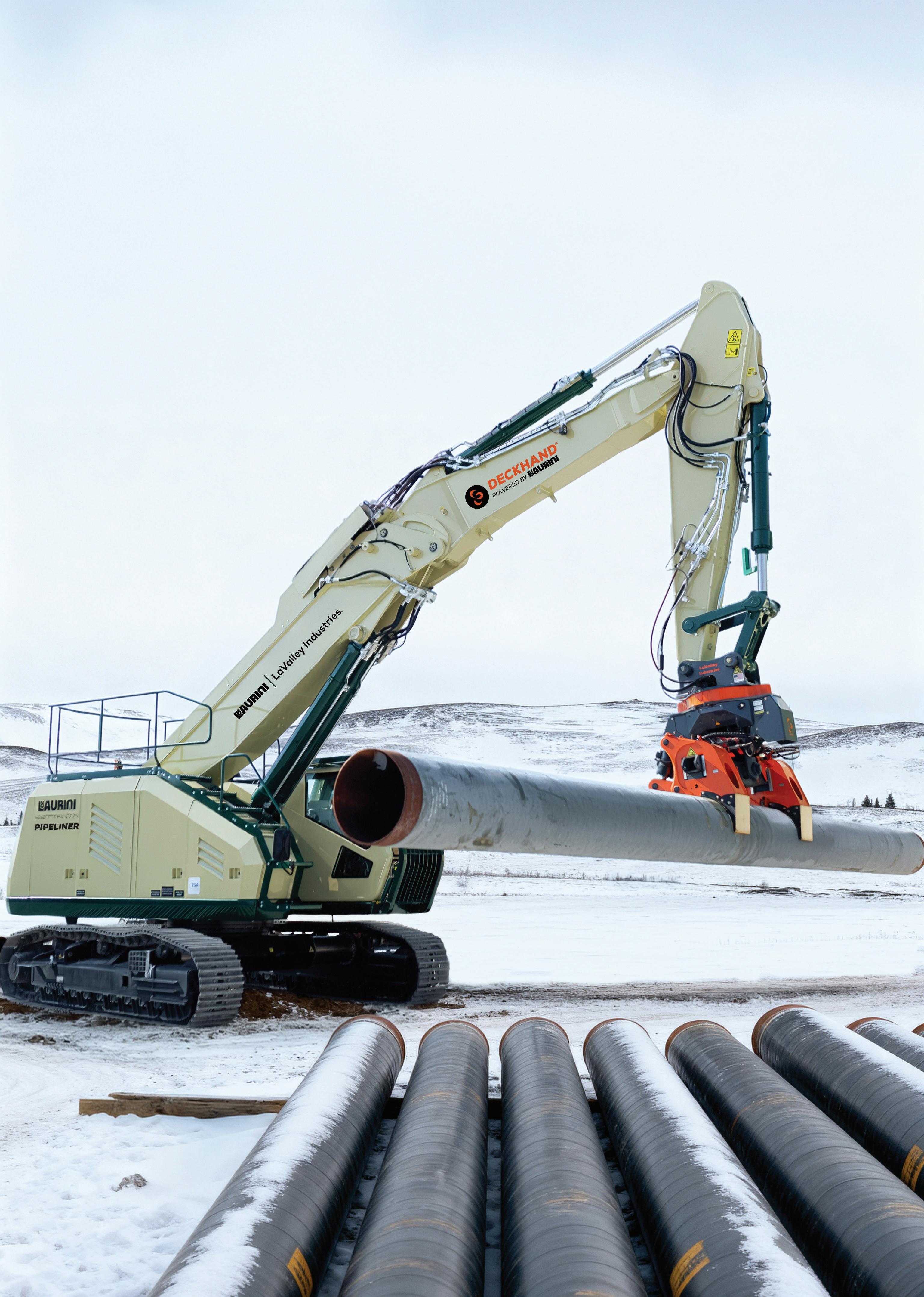
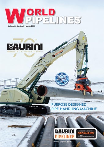
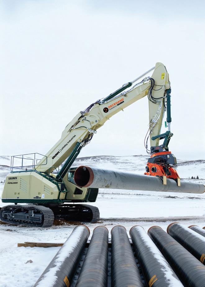
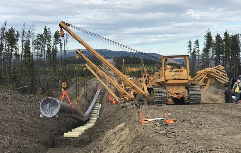
SETTANTA PIPELINER represents the next evolution in pipe handling equipment, advancing the excavator concept to perform multiple tasks in pipeline construction thanks to its interchangeable booms. Developed in collaboration between Laurini and LaValley Industries, it combines Laurini’s SETTANTA architecture with the DECKHAND system to deliver a unified, purpose-built solution for modern pipeline projects.




MANAGING EDITOR
James Little james.little@worldpipelines.com
ASSISTANT EDITOR
Emilie Grant emilie.grant@worldpipelines.com
SALES DIRECTOR
Rod Hardy rod.hardy@worldpipelines.com
SALES MANAGER
Chris Lethbridge chris.lethbridge@worldpipelines.com
SALES EXECUTIVE
Daniel Farr daniel.farr@worldpipelines.com
PRODUCTION DESIGNER
Siroun Dokmejian siroun.dokmejian@worldpipelines.com
HEAD OF EVENTS
Louise Cameron louise.cameron@worldpipelines.com
EVENTS COORDINATOR
Chloe Lelliott chloe.lelliott@worldpipelines.com
DIGITAL EVENTS COORDINATOR
Merili Jurivete merili.jurivete@palladianpublications.com
DIGITAL CONTENT COORDINATOR
Kristian Ilasko kristian.ilasko@worldpipelines.com
JUNIOR VIDEO ASSISTANT
Amélie Meury-Cashman amelie.meury-cashman@worldpipelines.com
SENIOR WEB DEVELOPER
Ahmed Syed Jafri ahmed.jafri@worldpipelines.com
DIGITAL ADMINISTRATOR
Nicole Harman-Smith nicole.harman-smith@worldpipelines.com
ADMINISTRATION MANAGER
Laura White laura.white@worldpipelines.com
Palladian Publications Ltd, 15 South Street, Farnham, Surrey, GU9 7QU, UK
Tel: +44 (0) 1252 718 999 Website: www.worldpipelines.com Email: enquiries@worldpipelines.com
Annual subscription £60 UK including postage/£75 overseas (postage airmail). Special two year discounted rate: £96 UK including postage/£120 overseas (postage airmail). Claims for non receipt of issues must be made within three months of publication of the issue or they will not be honoured without charge. Applicable only to USA & Canada: World Pipelines (ISSN No: 1472-7390, USPS No: 020-988) is published monthly by Palladian Publications Ltd, GBR and distributed in the USA by Asendia USA, 701C Ashland Avenue, Folcroft, PA 19032. Periodicals postage paid at Philadelphia, PA & additional mailing offices. POSTMASTER: send address changes to World Pipelines, 701C Ashland Avenue, Folcroft, PA 19032.

SENIOR EDITOR Elizabeth Corner elizabeth.corner@worldpipelines.com
This month, we bring to you two keynote articles about carbon capture and storage (CCS) pipelines. DNV presents Skylark on p. 8: a three year JIP designed to strengthen confidence in the safety of CO2 pipeline transport as CCS is built out globally. The project brings together partners including the UK HSE Science Division, the University of Arkansas, NCAS and DESNZ to generate high-quality empirical data on dense-phase CO2 behaviour. Through large-scale release testing at Spadeadam in the UK, dispersion modelling, terrain and weather studies, emergency response simulations, and research into impurities and monitoring technologies, Skylark aims to validate safety models, inform regulation, and support robust CCS safety guidelines. Ultimately, it seeks to provide the scientific foundation, training, and collaboration needed to enable safe, large-scale CO2 transport infrastructure worldwide.
Black & Veatch weighs in on CCS too (p. 13), outlining how, as demand for carbon removal and CCS accelerates, industries such as power generation, cement, pulp and paper, and ethanol are increasingly capturing CO2 not only to cut emissions but to create new revenue streams through utilisation, sequestration, and voluntary carbon markets. However, as Algert Prifti, CCUS Solutions Portfolio Manager at Black & Veatch, points out: limited pipeline infrastructure risks stranding otherwise viable projects.
To bridge this gap, liquid CO2 (LCO2) transport by truck or rail is emerging as a flexible alternative, to connect dispersed emitters to centralised storage or utilisation hubs. By capturing, liquefying, transporting, and then recompressing CO2 for pipeline injection or direct sequestration, operators are finding they can monetise emissions while overcoming current infrastructure constraints.
Yet while interim logistics solutions are valuable, large-scale decarbonisation ultimately depends on dedicated, well-planned pipeline networks. Transport infrastructure is the backbone of any CCS system: it links capture to storage, underpins investor confidence, and determines whether projects move beyond pilot stage. Without sufficient pipeline capacity – and the regulatory clarity and public confidence that must accompany it – the pace of deployment will inevitably slow.
Around the world, the most hard-to-abate sectors, including steel, cement, aviation, shipping and chemicals, need a clear, commercially viable path to decarbonisation. Wood Mackenzie forecasts that while absolute emissions from hard-to-abate sectors will fall through to 2050, they will do so more slowly than other sectors, and their combined share of global carbon emissions will rise from 21% today to 27% by 2050.1 In a recent blog post – ‘Is there still life in decarbonising hard-to-abate sectors?’ – Wood Mackenzie writes that: “Low-carbon fuels – including biofuels (aviation), hydrogen or electrification (steel), or calcined clays (cement) – are one option. Carbon capture, utilisation and storage (CCUS) bolted onto legacy fossil fuel-based operations (steel, cement) is another. High costs, however, remain the major hurdle to commercialisation and industrial scalability. Policy shifts, not least in the US after 2025’s One Big Beautiful Bill Act, have also dampened the industry’s appetite for investment.”1
The message is clear: ambition alone does not carry CCS. Delivering it properly requires integrated transport systems designed for growth, resilience, and long-term safety. The endeavour requires collaboration with pipeline stakeholders, and it requires confidence: in the data, in the safety case, and in the commercial model.
These themes will sit at the heart of the upcoming World Pipelines CCS Forum, where we will bring together operators, engineers, decision-makers and technology providers to examine what it really takes to build out CO2 pipeline networks nationally in the UK.2 From materials selection and fracture control to routing, regulation and phased capacity expansion, the focus will be firmly on execution. If CCS is to move from policy aspiration to industrial reality, pipelines must move with it.
1. www.woodmac.com/blogs/the-edge/is-there-still-life-in-decarbonising-hard-to-abate-sectors/ 2. www.worldpipelines.com/ccsforum2026
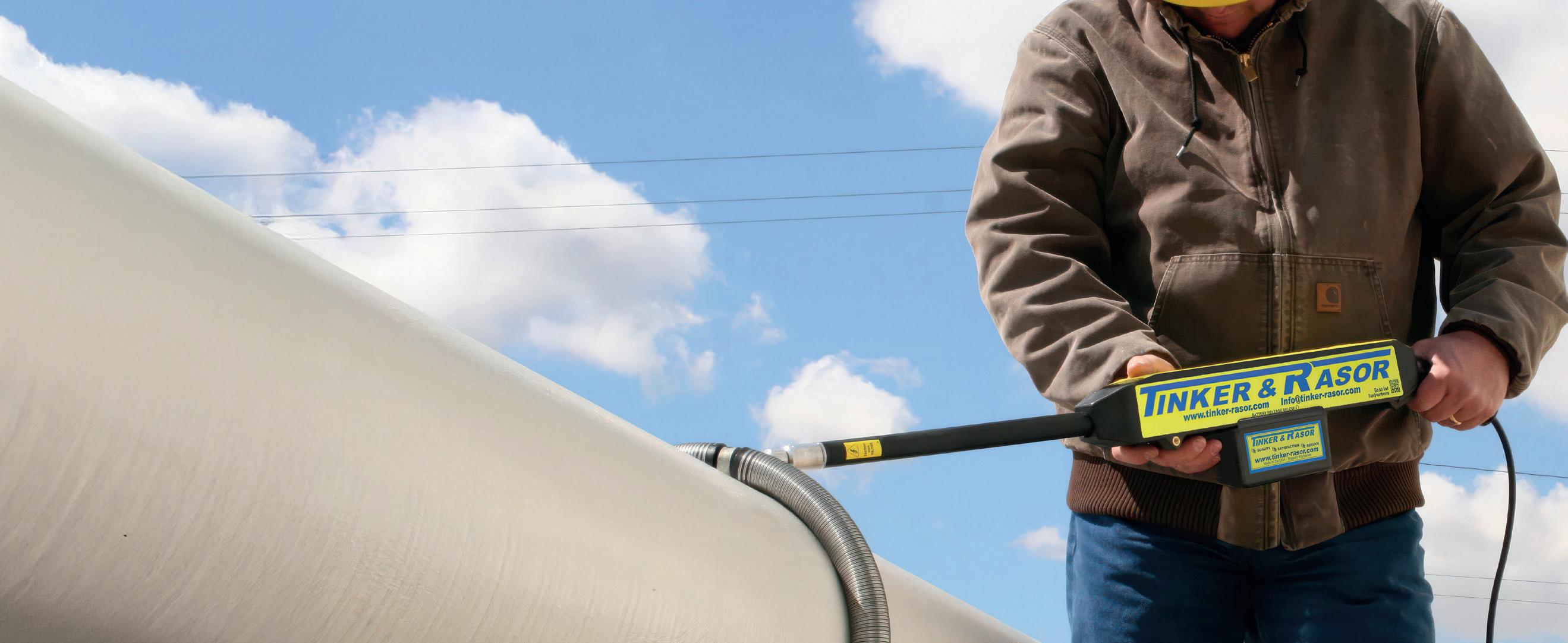
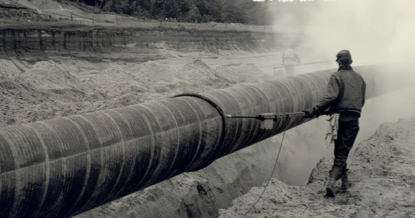
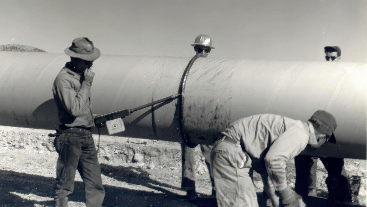
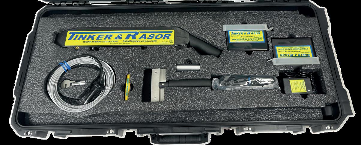
Since 1948, Tinker & Rasor has been a trusted name in holiday detection, relied upon by pipeline professionals worldwide. For over 76 years, our holiday detectors have set the benchmark for performance and reliability, ensuring the integrity of protective coatings by detecting coating flaws with precision. With a legacy of innovation and toughness, Tinker & Rasor continues to lead the industry, delivering cutting-edge solutions to safeguard pipeline coatings and maintain quality standards across the globe.
A rethink of the European Union’s (EU) Arctic policy could keep Norway’s Barents Sea gas in play in the 2030s, offering Europe a nearby, low-emission supply option as its reliance on the global LNG market grows, according to new Rystad Energy research and analysis.
The European Commission is reviewing its 2021 Arctic policy and has opened a public consultation until 16 March 2026. With Barents projects typically needing five to 10 years to move from discovery to steady output, the signal the EU sends now will determine whether additional volumes from already-open Norwegian acreage are ready for the mid-2030s, or whether Europe will lean even more heavily on global LNG in the next decade.
Rystad Energy’s analysis suggests that the EU could boost production in the Barents Sea by drawing a clearer boundary, both geographically and operationally, without necessarily weakening its climate stance. By defining the ‘Arctic’ scope more narrowly and tying any eligibility to explicit emissions and environmental requirements, the EU could avoid treating Norway’s already-open Barents acreage the same as frontier areas. The approach would still be contested among environmental groups, and it wouldn’t change the underlying trade-offs around Arctic drilling, but it could influence how buyers and policymakers weigh supply options during the 2030s. In Rystad Energy’s base case scenario for the EU27 plus
the UK, Norway supplies about 20 - 30% of gas demand through 2050, with LNG rising from 30 - 50% during the same period, increasing Europe’s exposure to global markets.
The resource base is substantial, but converting it into deliverable supply is less than straightforward. The parts of the Barents Sea already open to exploration, according to Norwegian Offshore Directorate estimates, hold around 3.5 billion boe of natural gas, or about 22 trillion ft3. Rystad Energy estimates producing fields and projects expected to be sanctioned by 2030 will contribute combined output of roughly 2.25 billion boe through 2050. Additional output beyond that would likely depend on new discoveries, coordinated development across multiple fields and, crucially, export capacity.
Infrastructure is a significant swing factor and could limit long-term scalability. A 2023 study by Gassco and the Norwegian Offshore Directorate found that new Barents export capacity can be socio-economically profitable if sufficient volumes are proven. Today, the region’s main outlet is Hammerfest LNG, an export terminal in the far north, but it remains largely tied to the Snøhvit field, which limits flexibility to absorb any new volumes. A pipeline connection south into the Norwegian Sea network is one potential route, but it would require enough scale and synchronised timelines across projects to be financeable.
Romanian oil pipeline operator Conpet discloses cyberattack
Romania’s national oil pipeline operator, Conpet, disclosed a cyberattack in February that disrupted its corporate IT systems and temporarily took its website offline.
The incident did not impact pipeline operations or the company’s ability to meet contractual obligations. Conpet is investigating the breach and restoring systems with support from national cybersecurity authorities, and has notified
DIICOT, filing a criminal complaint. Although Conpet has not confirmed the attack type, the Qilin ransomware gang has claimed responsibility, listing the company on its dark web leak site. The group alleges it stole nearly 1TB of data and has published sample documents, including financial records and passport scans, as proof.
Wood Mackenzie: UK Energy Transition Outlook shows 12-point gap on 2030 climate target despite £1.5 - 2.1 trillion investment pathway to 2060
The UK has reached crunch time on climate commitments, with nearly all 2030 energy transition targets now out of reach despite cutting emissions in half since 1990, according to Wood Mackenzie’s ‘United Kingdom Energy Transition Outlook 2025’.
The analysis shows the UK must close a 12-percentagepoint gap by 2030, requiring an additional £75 billion in accelerated investment this decade, while cumulative lowcarbon spending needs will reach £1.5 - 2.1 trillion by 2060. A ban on North Sea exploration has locked in structural dependence on oil and gas imports, even as offshore wind deployment lags 20% behind government targets.
The UK slashed energy-related CO2 emissions from approximately 600 million tonnes per year in 1990 to 294 million tpa in 2025, a 51% reduction over 35 years. The government followed this success with an ambitious 2035 Nationally Determined Contribution target. However, Wood Mackenzie’s base case projects only a 56% reduction by
2030 against the NDC target of 68%.
Amidst what the analysis describes as a “new world order,” national security priorities and economic pressures now compete with climate policy for government attention and budget allocation. Defence spending and cost-of-living concerns are pulling resources away from climate initiatives, and the climate-motivated energy transition is losing urgency. Yet domestic low-carbon energy has become central to UK autonomy and global influence, creating a strategic imperative that extends beyond emissions targets.
Oil demand falls 24% and gas demand declines 18% by 2035 in Wood Mackenzie’s base case, yet fossil fuels remain critical. Transport accounts for 72% of oil demand, while residential, commercial and agriculture sectors represent 54% of gas demand. Gas still generates 22% of power in 2030 and 10% in 2035 despite clean power targets.
10 March - 11 March 2026
StocExpo 2026
Rotterdam, The Netherlands
https://www.stocexpo.com/en/
Northern Endurance Partnership and The Crown Estate sign lease for UK’s first CCS project ahead of offshore construction
The Northern Endurance Partnership (NEP) and The Crown Estate have signed a lease paving the way for the UK’s first and largest commercial-scale CO2 transportation and storage asset.
15 - 19 March 2026
AMPP Annual Conference + Expo
Houston, USA
https://ace.ampp.org/home
18 March 2026
World Pipelines CCS Forum
London, UK
https://www.worldpipelines.com/ccsforum2026
20 - 24 April 2026
PLCAC convention
Maui, Hawaii
https://pipeline.ca/
27 - 30 April 2026
Pipeline Technology Conference (PTC)
Berlin, Germany
https://www.pipeline-conference.com/
4 - 7 May 2026
Offhore Technology Conference (OTC)
Houston, USA
https://2026.otcnet.org
2 - 3 June 2026
Gas, LNG & The Future of Energy 2026 London, UK
https://www.woodmac.com/events/gas-lngfuture-energy/
9 - 11 June 2026
Global Energy Show 2026
Calgary, Canada
https://www.globalenergyshow.com/
14 - 17 September 2026
Gastech 2026
Bangkok, Thailand
https://www.gastechevent.com
The landmark agreement establishes the UK’s first commercial-scale lease of the seabed for permanent offshore CO2 storage and associated pipeline infrastructure, providing a template for future carbon capture and storage (CCS) projects around the UK’s coastline.
Following an Agreement for Lease in September 2023, the lease signing is a critical milestone towards installing the infrastructure for the Endurance carbon store – a saline aquifer located approximately 140 km offshore in the southern North Sea which, together with
Penspen awarded major CO2 pipeline study in Switzerland
Penspen has been awarded a pre-FEED study by CO2 Pipeline Schweiz AG to support the development of a national CO2 transport system in Switzerland.
The study focuses on the high-level design of a CO2 pipeline corridor between Basel and Zurich, with consideration of onward connections across eastern and central Switzerland.
Penspen’s scope covers the technical design of the pipeline backbone and associated hubs, including intermediate valve stations, compressor stations and supporting infrastructure. The project will also provide routing support, site selection input, support to the economic evaluation and guidance on regulatory and standards alignment for CO2 transport within the Swiss context. The project is scheduled to complete in March 2027.
A key objective of the study is to help shape consistent technical and assessment standards for CO2 pipelines in Switzerland. These standards are intended to support future project development and provide a common reference for operators, regulators and stakeholders. Penspen has extensive engineering experience in long-length pipeline projects for the transportation of CO2, with recent work including the HyNet CO2 transportation pipeline at Liverpool Bay in the UK and a dense phase CO2 pipeline in the United Arab Emirates.
nearby stores, provides NEP with access to up to 1 billion t of CO2 storage capacity.
The lease, the first of its kind in the UK, covers NEP’s offshore pipeline corridor and storage site. It will run until injection at the store is complete, currently expected in the mid-2050s.
In December 2024, NEP reached financial close on the first phase of Teesside’s onshore infrastructure – serving NZT Power and future Teesside-based projects – and on the 145 km offshore pipeline to the Endurance Carbon Store. NEP was simultaneously awarded the UK’s first-ever carbon storage permit by the North Sea Transition Authority (NSTA). With all necessary consents secured, construction is underway, and start-up is expected in 2028.
• DNV launches Industrial Services to support rapidly expanding energy and infrastructure markets
• UCC Holding and PIPECARE Group sign JV at LNG2026
• Cadent unveils plans for new UK hydrogen pipeline to supply industry across the Humber, Lincolnshire and Nottinghamshire
• Shelli Myers elected Chair of Texas Pipeline Association; first woman to lead TPA
• Wood and Kellas Midstream extend operating partnership at the CATS facility
Follow us on LinkedIn to read more linkedin.com/showcase/worldpipelines

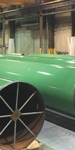

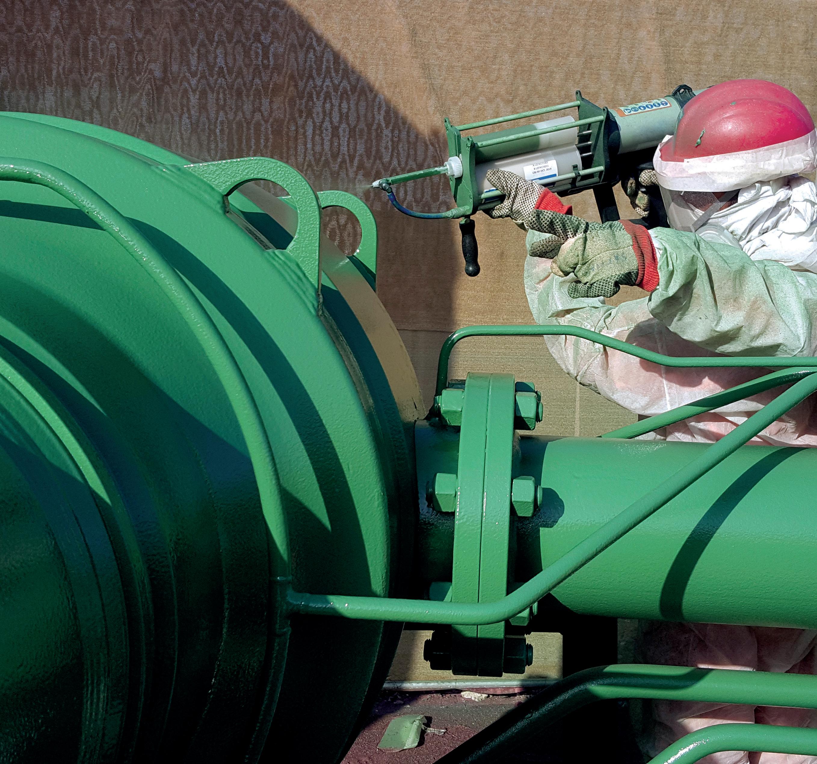
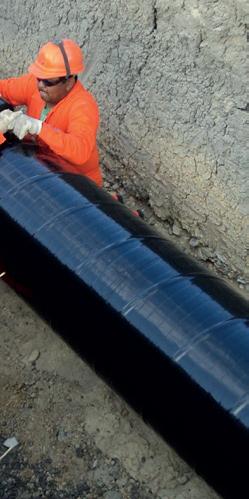
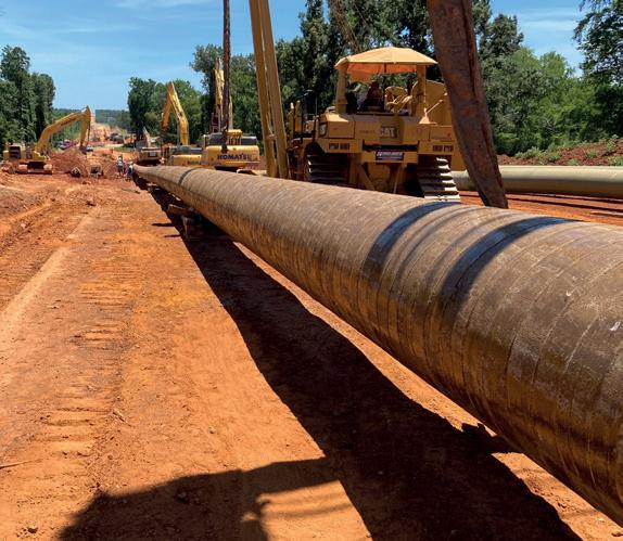
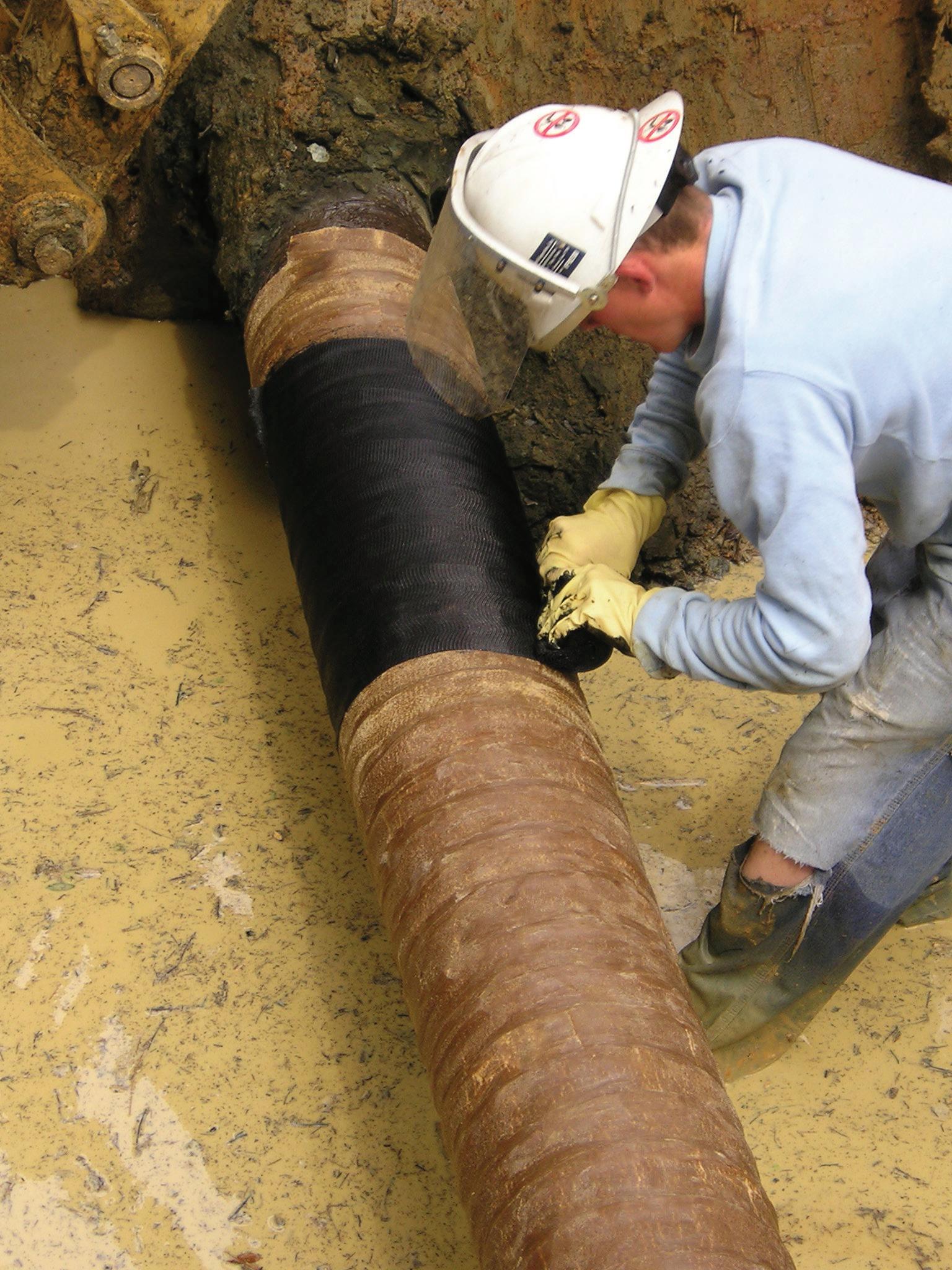
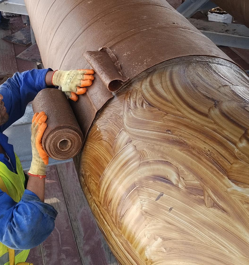
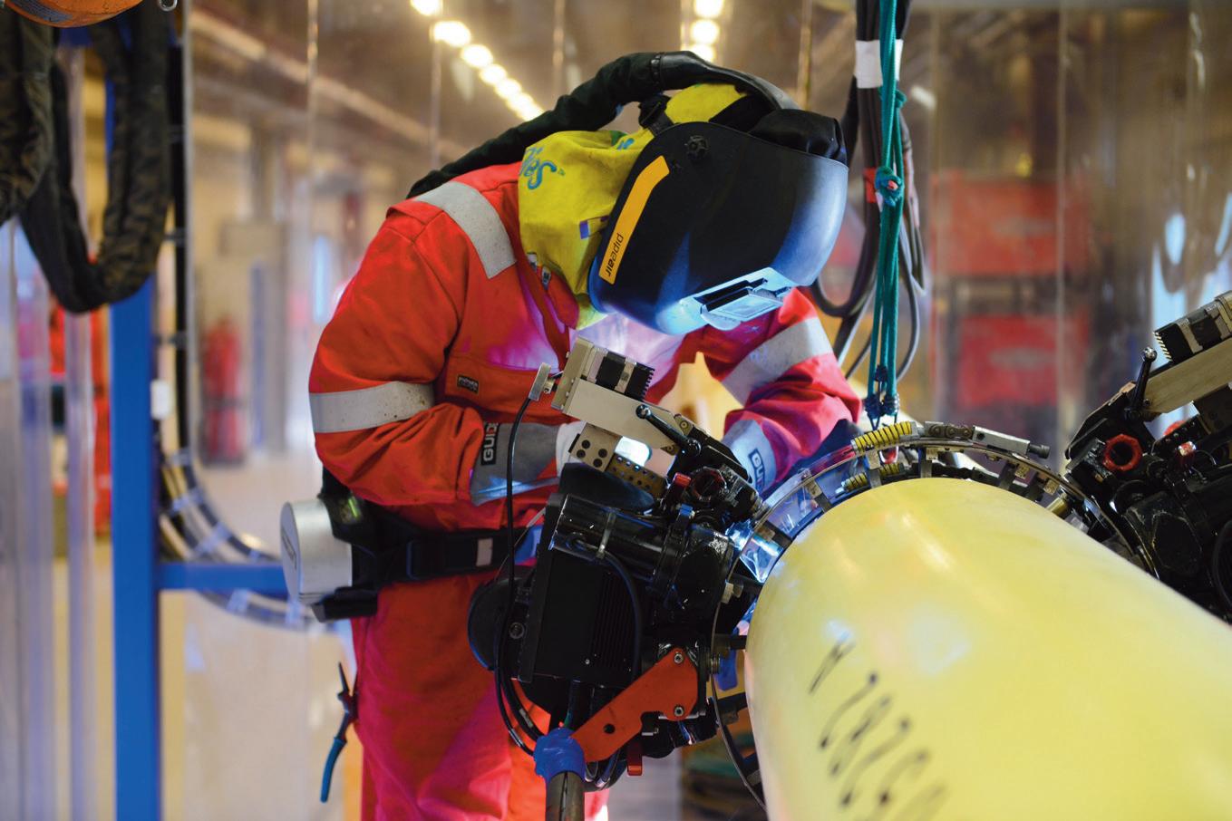
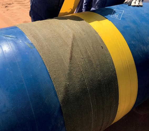
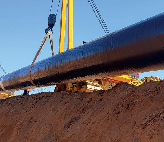
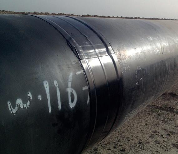
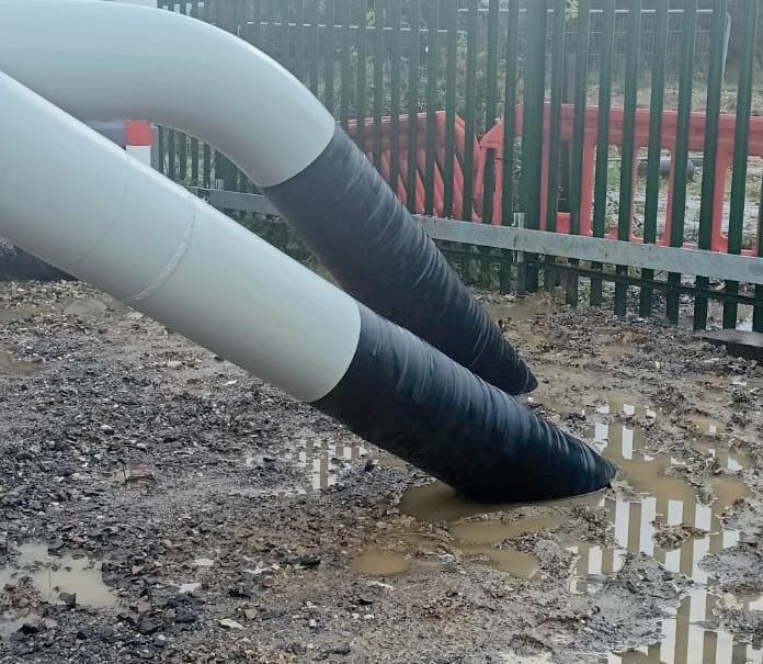
PROTECTIVE OUTERWRAPS
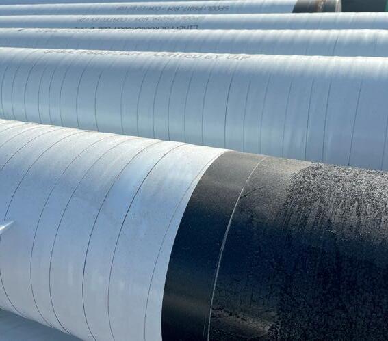
VISCOELASTIC COATINGS
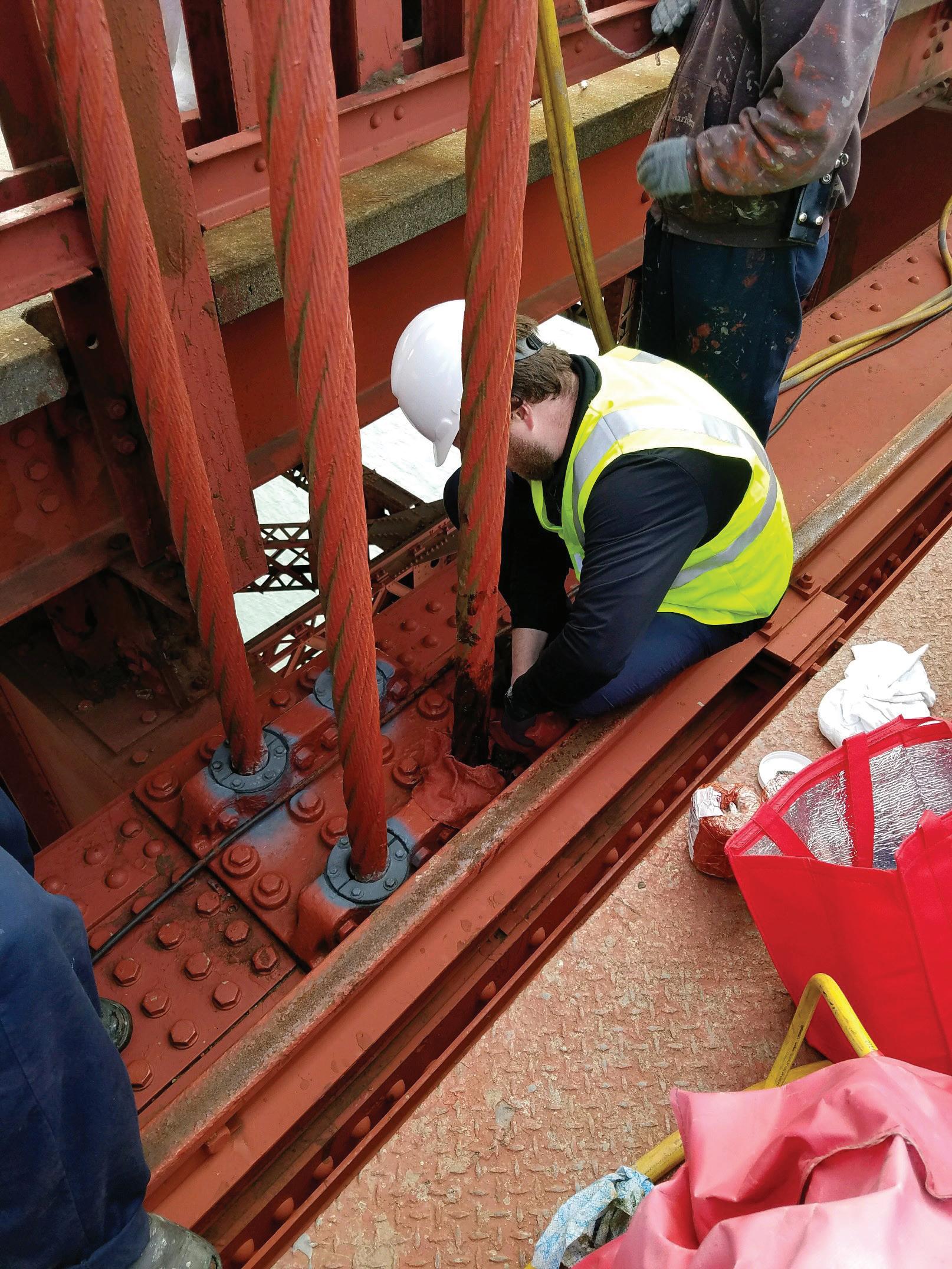
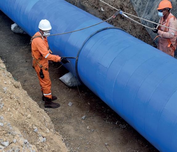
SOIL-TO-AIR
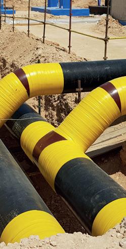
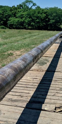
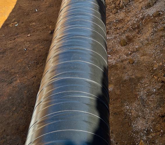
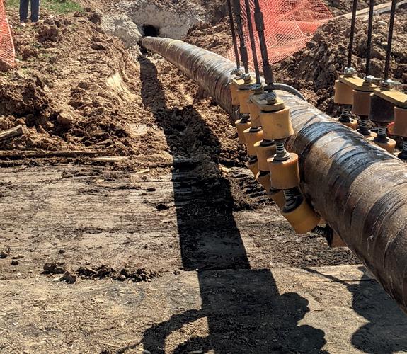
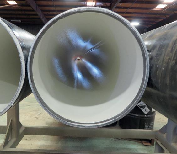
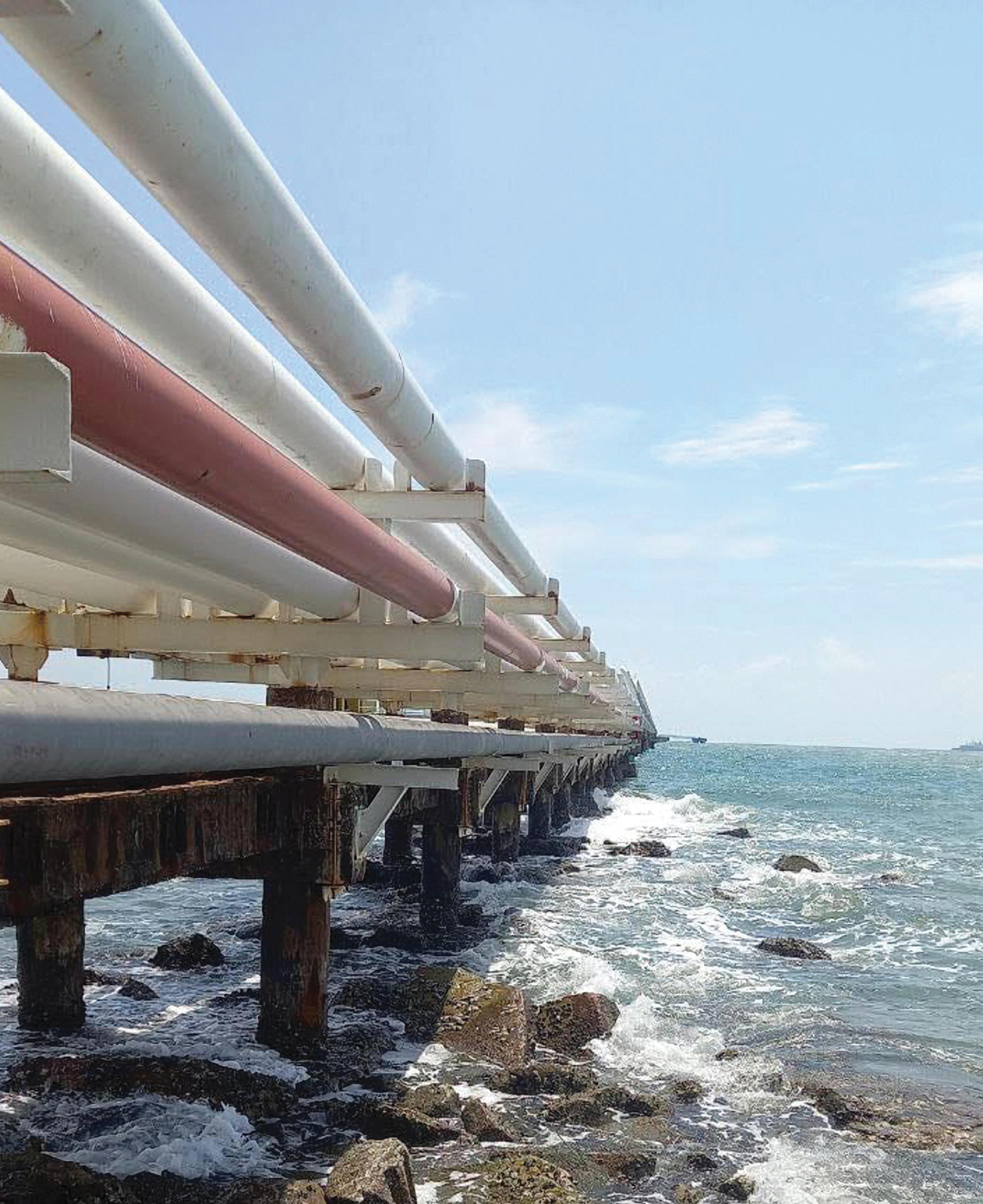
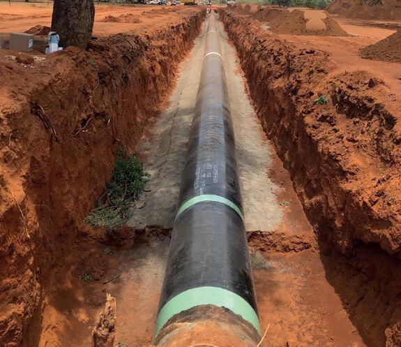
INTERNAL PIPE LININGS

Hari Vamadevan, Senior Vice President and Regional Director, UK and Ireland, Energy Systems, DNV, outlines the Skylark JIP as it leads the global effort to advance CO2 pipeline safety.
As the global community intensifies efforts to meet net-zero emissions targets, carbon capture and storage (CCS) is emerging as a cornerstone of industrial decarbonisation.
From cement and steel, to chemicals and power generation, CCS offers a viable pathway to reduce emissions from sectors where electrification or fuel switching is not yet feasible. But capturing carbon is only part of the equation: transporting it safely and efficiently is equally critical.
Recognising this challenge, DNV has launched Skylark, a pioneering Joint Industry Project (JIP) aimed at advancing the global understanding of CO2 pipeline operations.
This three year initiative is designed to equip regulators, operators, and emergency responders with the highest quality data and insights to support safe, scalable CCS deployment.
A collaborative effort for a complex challenge
Skylark is being developed in collaboration with a consortium of leading scientific and regulatory bodies, including the UK Health and Safety Executive Science Division (HSE SD), the University of Arkansas, Ricardo’s UK National Chemical Emergency Centre, the National Centre for Atmospheric Science (NCAS), and the UK Department for Energy Security and Net Zero (DESNZ).
This multidisciplinary partnership reflects the complexity of CO2 pipeline safety. Unlike natural gas, CO2 behaves as a dense phase fluid under pipeline conditions and can form ground-hugging vapour clouds when released. These clouds pose unique risks to human health and the environment, particularly in the event of accidental releases.
Skylark addresses one of the biggest barriers to CCS adoption – confidence in safe operations at scale. By combining decades of pipeline expertise with new technologies, we’re helping build the infrastructure needed to meet net-zero targets.
According to DNV’s Energy Transition Outlook 2024, the global CO2 pipeline network must expand from approximately 9500 km today to over 200 000 km by 2050. This represents a more than twentyfold increase in just 25 years – a scale-up that is unprecedented in the history of pipeline infrastructure.
This expansion will require not only massive investment in materials, engineering, and construction but also a robust safety framework grounded in empirical evidence. Skylark is designed to provide that foundation.
Four pillars of research and innovation
Skylark is structured around four core research pillars, each addressing a critical aspect of CO2 pipeline safety:
1. Crater formation and dispersion modelling
Understanding the physical consequences of pipeline failure is essential for designing safe systems. Skylark will conduct large-scale experiments at DNV’s Spadeadam Research and Development Facility in Cumbria, UK, to simulate highpressure CO2 releases. These tests will examine crater formation, jet dynamics, and dispersion patterns under controlled conditions.
The data generated will be used to validate computational fluid dynamics (CFD) models, which are critical for predicting the behaviour of CO2 in real-world scenarios. These models will inform pipeline routing decisions, setback distances, and emergency planning.
2. Terrain and weather effects on dense vapour clouds
CO2 dispersion is highly sensitive to terrain and meteorological conditions. Unlike lighter-than-air gases, CO2 tends to stay close to the ground, especially in low-lying areas or under stable atmospheric conditions. This can lead to prolonged exposure risks in the event of a leak.
To study these effects, Skylark will combine field experiments with wind tunnel testing at the University of Arkansas. These tests will simulate various topographies –such as valleys, hills, and urban environments – and weather patterns to understand how CO2 clouds behave in complex environments.
3. Emergency response protocol validation
Effective emergency response is a cornerstone of pipeline safety. Skylark will work closely with first responders, emergency planners, and public safety officials to test and refine response protocols. Real-world simulations will be conducted at Spadeadam, involving live CO2 releases and coordinated response drills.
These exercises will help identify gaps in current procedures, improve communication strategies, and ensure that responders are equipped with the knowledge and tools needed to manage CO2 incidents safely.
4. Early engagement and industry momentum
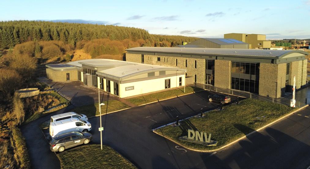
Skylark has already attracted significant interest from industry, with ten organisations currently participating. A major milestone was the 2024 workshop held at DNV’s Spadeadam
facility, which displayed prototype testing equipment, preliminary dispersion models, and the project’s research roadmap.
The event drew a diverse audience of engineers, regulators, emergency planners, and academic researchers, highlighting the broad relevance of Skylark’s objectives. Feedback from participants emphasized the value of empirical data, cross-sector collaboration, and the need for harmonised safety standards.
With major experiments beginning in 2026, we invite additional industry partners to join this collaborative effort. The findings will directly inform DNV’s CCS Safety Guidelines and help operators worldwide deploy pipelines with confidence.
One of Skylark’s most important contributions will be its role in shaping regulatory frameworks for CO2 transport. By generating high-fidelity data and validated models, the project will provide a scientific foundation for safety standards, risk assessments, and permitting processes.
CO2 pipeline safety presents unique technical challenges. For example, CO2 can transition between gas, liquid, and supercritical phases depending on pressure and temperature. These phase changes affect flow dynamics, leak behaviour, and dispersion characteristics.
Moreover, impurities in captured CO2 – such as water, nitrogen, or sulfur compounds – can influence corrosion rates, phase stability, and safety risks. Skylark will explore how these impurities affect pipeline integrity and release scenarios, contributing to more accurate risk assessments.
The project will also investigate the use of advanced sensors, remote monitoring technologies, and predictive analytics to enhance pipeline safety. These innovations could enable real-time leak detection, automated shutdowns, and improved incident response.
Beyond research, Skylark will play a key role in training and capacity building. The project will develop educational materials, simulation tools, and training
modules for engineers, regulators, and emergency responders.
Workshops, webinars, and field demonstrations will be organised to share findings and promote best practices. These efforts will help ensure that the knowledge generated by Skylark is widely disseminated and applied across the CCS value chain.
A model for collaborative innovation
Skylark exemplifies the power of collaborative innovation. By bringing together academic institutions, government agencies, emergency services, and private industry, the project ensures that its findings are not only scientifically rigorous but also practically applicable.
The involvement of the UK’s National Chemical Emergency Centre and NCAS ensures that atmospheric modelling and chemical hazard expertise are integrated into the project’s outputs. Meanwhile, the University of Arkansas contributes cutting-edge wind tunnel research capabilities, enabling controlled studies of CO2 dispersion under varied conditions.
This multidisciplinary approach ensures that Skylark’s outputs are robust, comprehensive, and globally relevant.
Over the next two years, Skylark will deliver a series of technical reports, safety guidelines, and training materials. These outputs will be made available to project partners and, where appropriate, to the broader CCS community.
Key deliverables will include:
) Validated CO2 dispersion models for varied terrain and weather conditions.
) Emergency response best practices, including training modules and simulation scenarios.
) Recommendations for pipeline routing and setback distances, based on empirical data.
These deliverables will feed directly into DNV’s CCS Safety Guidelines, which are widely used by operators, regulators, and engineering firms around the world.
The path to net zero is not just about ambition – it’s about execution. As industries and governments invest in CCS as a climate solution, ensuring the safety and reliability of CO2 transport infrastructure is nonnegotiable.
Skylark represents a bold and necessary step toward that goal. By combining empirical research, advanced modelling, and real-world testing, DNV and its partners are not only advancing the science of CO2 pipeline safety – they are building the trust and confidence needed to scale CCS globally.
Skylark is about more than pipelines. It is about enabling the energy transition with confidence, clarity, and collaboration.

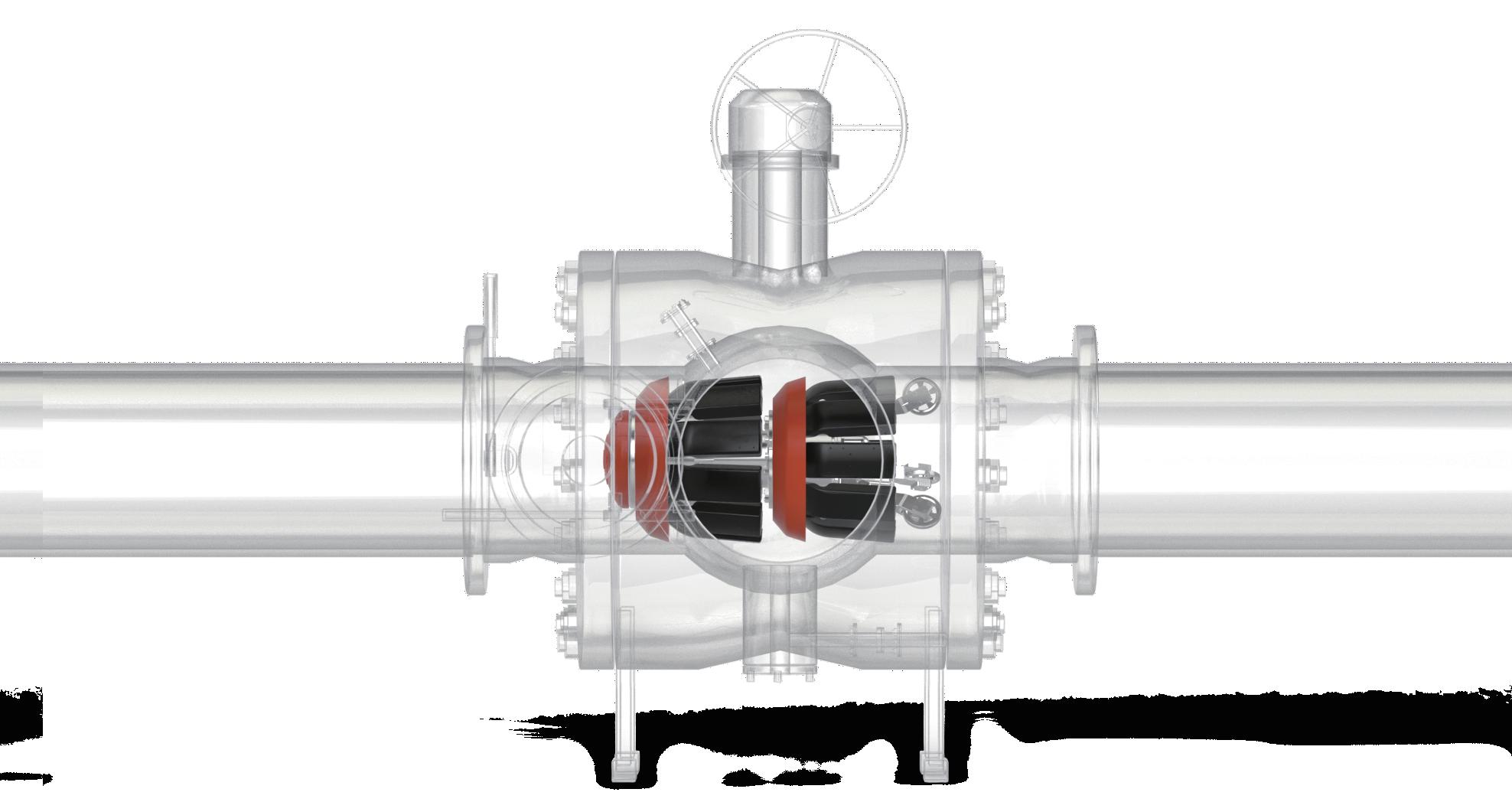
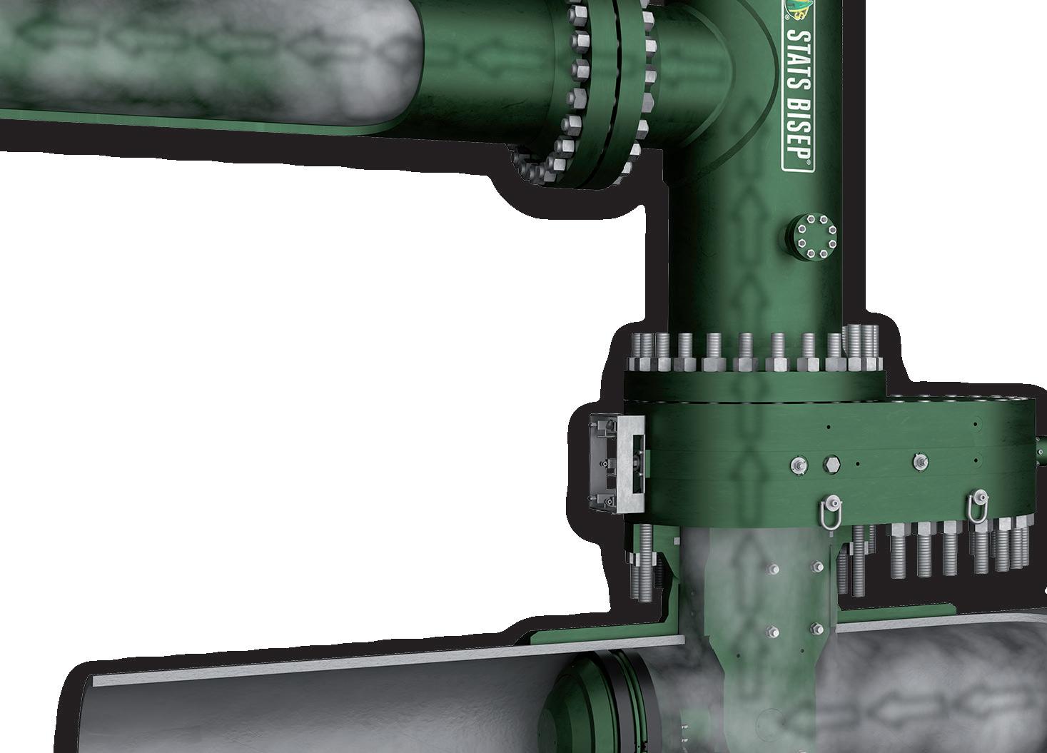
integrated bypass maintains production during isolation











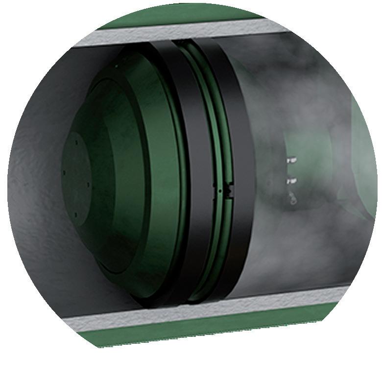
Dual Leak-Tight Seals
Double Block & Bleed Isolation


















Isolated Pipeline






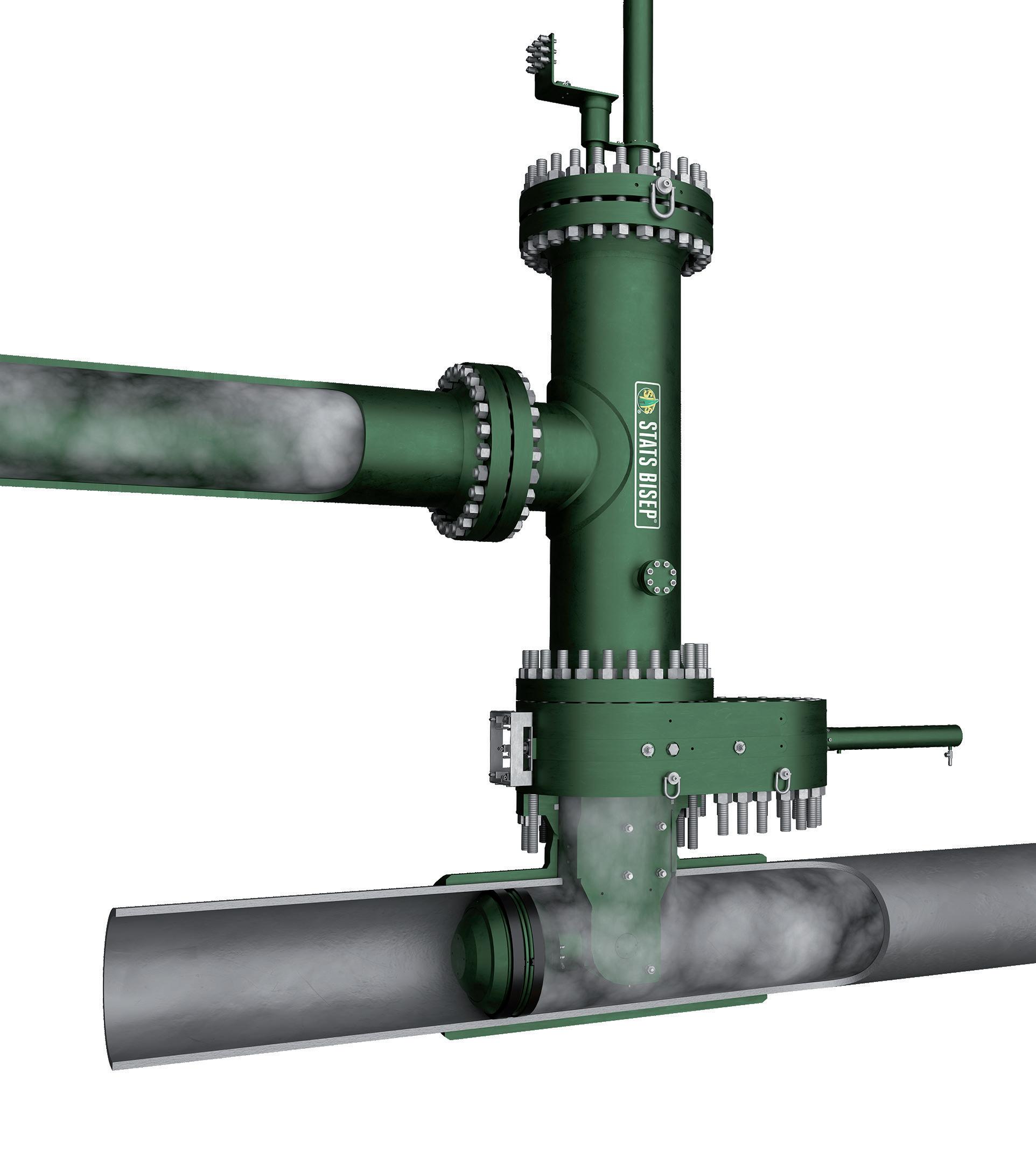



Monitored Zero-Energy Zone
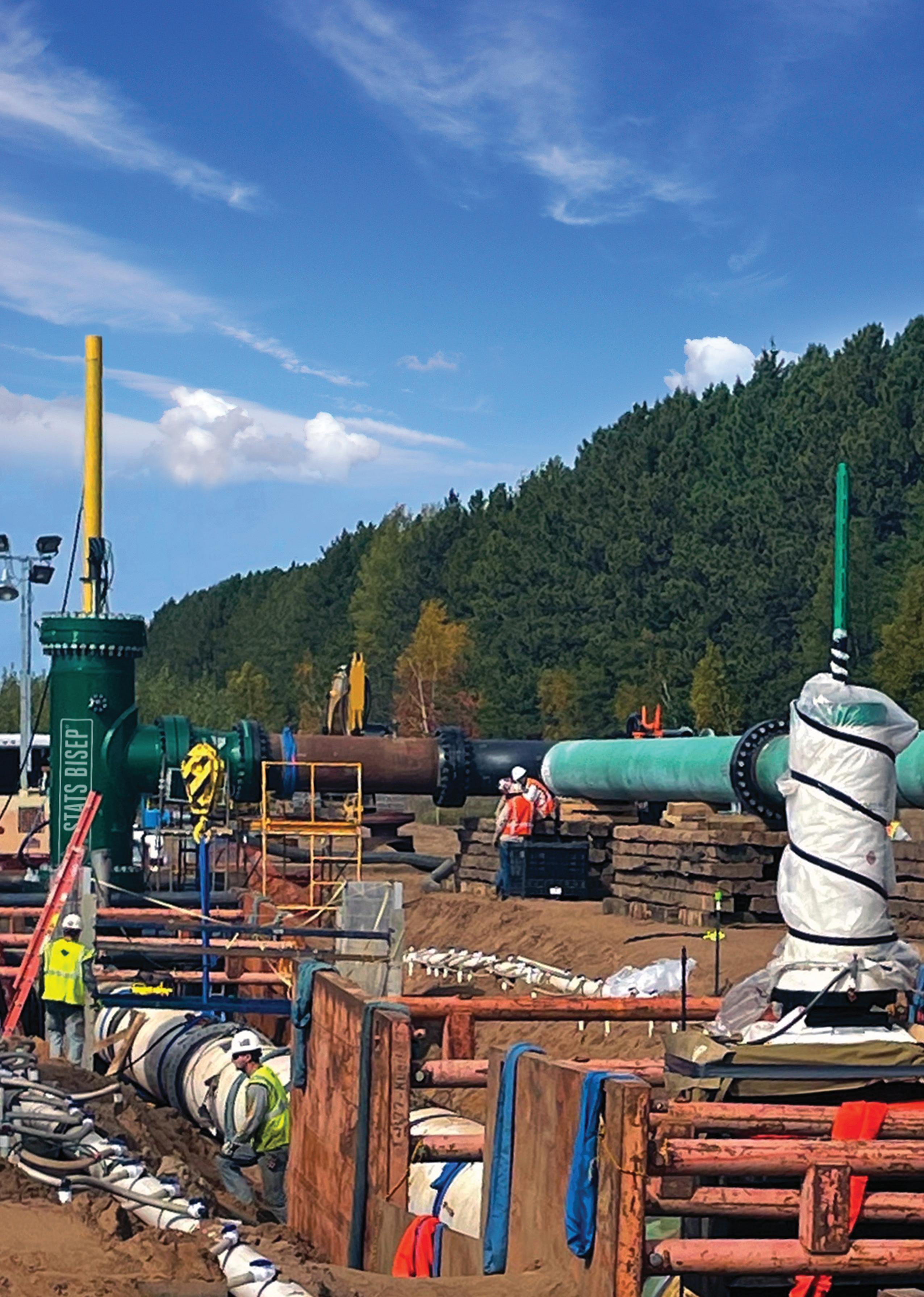
The BISEP® has an ex tensive track record and provides pioneering double block and bleed isolation while
dual seals provide tested, proven and fully monitored leak-tight isolation, ever y time, any pressure.























Algert Prifti, CCUS Solutions Portfolio Manager, Black & Veatch, presents flexible CO2 transport to maximise revenue, reduce emissions and monetise new and existing CO2 management infrastructure.
World economies, leading organisations and large corporations are pursuing carbon dioxide (CO 2 ) removal (CDR) and capture (CCS) solutions to deliver environmental
benefits, support near-term decarbonisation goals and create economic value through sustainable operations. Proven CDR and CCS solutions can be deployed across many industry sectors to reduce carbon intensity.
This includes industries such as energy utilities and power providers, cement production, pulp and paper and ethanol production. These sectors can now meet market demand for low-carbon intensity energy, including power and steam, paper products as well as low carbon fuels.
In addition to producing low carbon intensity products, these operations can generate a secondary revenue stream through financially attractive CO 2 offtake opportunities tied to transportation, utilisation and/or sequestration. Not all CO 2 is equally suitable for capture at the source, however. The viability of CO 2 offtake depends on the type and location of CO 2 source; the availability of pipeline infrastructure; readiness for CO 2 utilisation (such as CO 2 -enhanced oil recovery [CO 2 -EOR]); and/or the ability to sequester CO 2 through Class VI well injection into underground saline-reservoirs.
When captured using proven carbon capture technologies or processes, biogenic CO 2 from pulp and paper and ethanol operations can generate additional revenue through demand in the voluntary CDR market. This is a viable alternative to sequestering CO 2 with biogenic CO 2 currently being valued at up to US$1000/t.
This strong market demand for CDR and CCS is driving global scaleup efforts, which in turn require parallel near-term expansion of CO 2 transportation and sequestration infrastructure. While buried pipeline transportation of CO 2 has been successfully used for decades as part of the CO 2 -EOR operations, challenges remain in deploying new supercritical CO 2 pipelines. These include high costs, risks associated with long interstate pipeline conveyance, acquisition of land rights-of-way and public pushback related to environmental and community acceptance.
As such, the lack of new CO 2 pipeline availability or adequate capacity in existing CO 2 pipelines poses a risk to the feasibility of deploying economically viable low-carbon intensity projects. CO 2 sources at various sites may be economically viable but are effectively stranded due to their distance from existing or greenfield CO 2 transportation and sequestration.
To address this challenge, alternative CO 2 transportation methods using liquid CO 2 (LCO 2 ), such as truck or rail, are being considered, particularly to connect stranded assets across North America. LCO 2 can also provide the logistical flexibility and capacity versatility needed to support market deployment.
LCO 2 truck and rail transport solutions are not seen as competing alternatives to the new and/or
existing CO 2 pipeline transportation, but instead as an effective way to connect various CO 2 sources for monetisation of centrally and regionally located and scaled CO 2 capture infrastructure.
CO 2 truck and rail transport solutions focus on deploying commercially available, proven CO 2 processing facilities along with loading and unloading terminals and the additional infrastructure required for truck and rail access. Depending on emissions source and CO 2 concentration, flue and off-gas can be captured using approaches ranging from simple mechanical separation and blower-based routing to proprietary CO 2 capture technologies.
This approach is applicable to low concentration, post-combustion emission sources, as well as highconcentration process gases such as those present at ethanol facilities. After capture, the CO 2 product is dehydrated and routed through a liquefaction unit, where it is compressed and cooled into the liquid phase. In some cases, further purification of the CO 2 may be required prior to transfer to the necessary on-site, above-ground storage. Standardised LCO 2 loading systems for either truck or rail transport are readily available in the market.
Typically, this consists of a multi-bay approach for either top (rail) or rear-loading (truck). This configuration is used to facilitate the safe transfer of the LCO 2 into Department of Transportation (DOT)approved truck or rail carriers. Upon arrival at the unloading terminal, the LCO 2 is unloaded using the same multi-bay approach to transfer to LCO 2 to an above-ground storage. The stored LCO 2 is then further compressed via process pumps to reach a supercritical state. The supercritical CO 2 is then injected into a CO 2 pipeline lateral or directly into an injection well at the wellhead. The CO 2 is either utilised for CO 2 -EOR operations or sequestered deep in saline reservoirs for permanent geological storage.
Based on recent design experience at Black & Veatch, there is a demonstrated sweet spot among product storage, throughput capacity and transportation logistics and how these factors affect overall project economics. Larger LCO 2 truck and rail loadout capacity and increased onsite LCO 2 storage can streamline operations; however, these benefits must be balanced against transportation logistics, overall project capital and O&M costs. Achieving the right balance among these parameters is critical to making a project economically viable.
By monetising new and existing CO 2 management infrastructure, organisations can turn captured emissions into incremental revenue through transportation, utilisation, and sequestration pathways. Leveraging flexible solutions like liquid CO 2 logistics unlocks stranded assets, maximises the value of proven infrastructure and accelerates deployment of economically viable low carbon projects.
Dr. Awadh O. Al-Oadah, Director Projects, Pipeline Projects Department, Saudi Aramco, discusses how pipeline boundary conditions evolve during construction and commissioning rather than remaining fixed as assumed in design, and how recognising them as construction-dependent variables improves pipeline performance, safety, and lifecycle integrity.

Pipeline engineering analyses traditionally rely on boundary conditions defined early in the project lifecycle and treated as fixed throughout design, construction, and operation. Field experience from cross-country and facility-based pipeline projects, however, demonstrates that many construction-stage challenges and early operational issues arise not from incorrect calculations, but from boundary conditions that evolve differently in the field than assumed during design. Soil restraint, support behaviour, construction tolerances, installation sequencing, temporary works, site practices, and commissioning activities frequently redefine system constraints, influencing pipeline response in ways not fully captured by conventional design analyses. This article examines how boundary conditions develop throughout pipeline project execution, why pipeline systems are often highly sensitive to these effects, and how treating boundary conditions as constructiondependent variables can improve design robustness, reduce rework, enhance safety, and support long-term pipeline integrity and lifecycle performance.
Pipeline engineering is supported by mature international standards, established analytical methodologies, and increasingly advanced software tools. Stress analysis, hydraulic modelling, geotechnical assessment, and constructability reviews are routinely performed to demonstrate compliance and fitness for service. These analyses depend fundamentally on the definition of boundary conditions, which enable engineers to convert real systems into solvable models.
Despite the maturity of pipeline engineering practice, many projects experience difficulties during construction, commissioning, or early operation. These difficulties often manifest as unexpected stresses, unanticipated movement, support overloading, hydrotest challenges, difficulties during tie-ins, or early integrity concerns. In many cases, these issues arise even though the design meets all applicable code requirements and has been reviewed and approved.
Post-project reviews frequently reveal a common theme: the governing assumptions were not incorrect equations or inappropriate material properties, but boundary conditions that did not form in the field as assumed during design. The pipeline behaved differently not because the physics was wrong, but because the constraints defining that physics evolved during construction.
This article argues that boundary conditions in pipeline projects should be understood not as fixed design inputs, but as construction-dependent variables that develop over time. Recognising this distinction provides a more realistic framework for anticipating pipeline behaviour and managing risk across the project lifecycle.
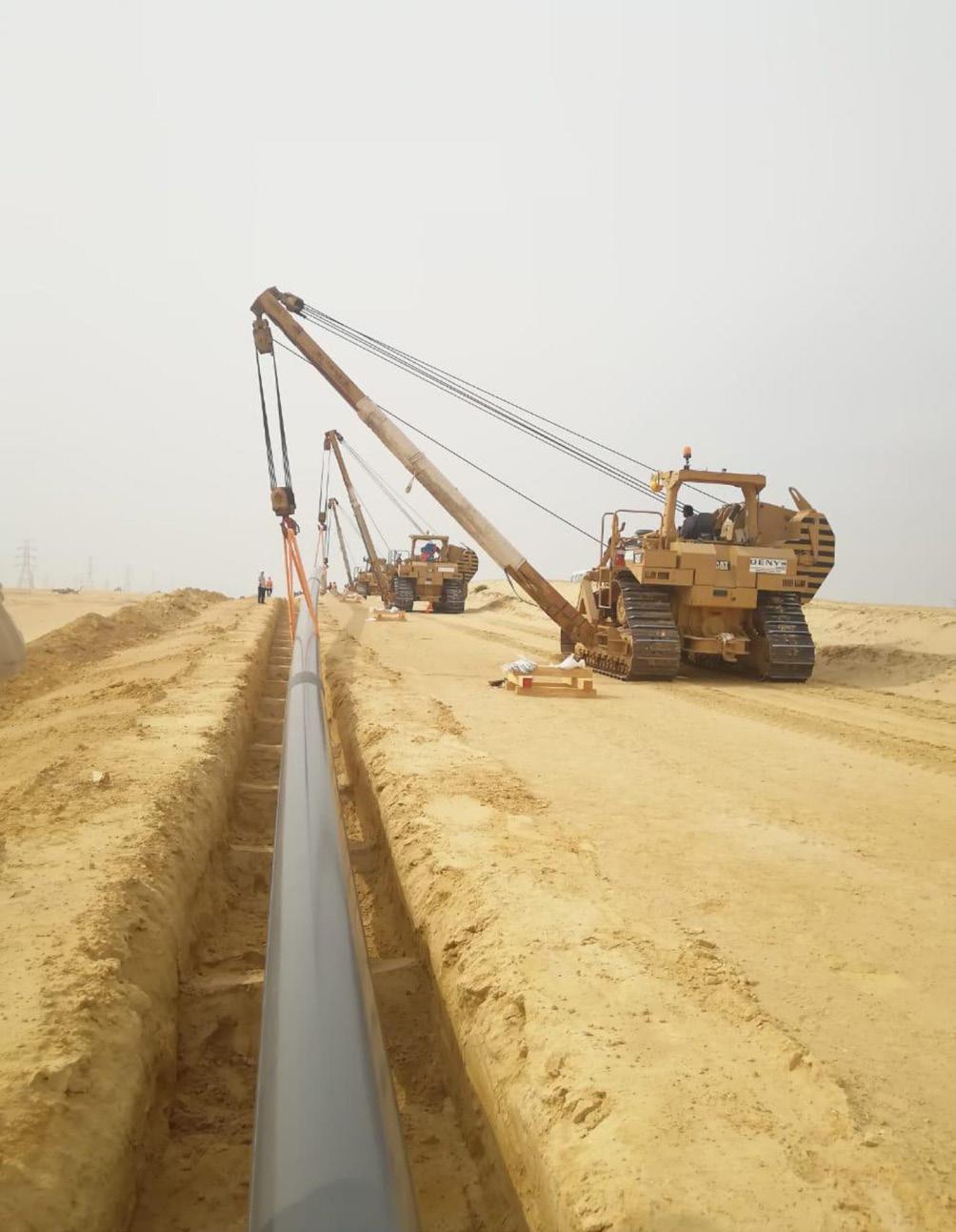
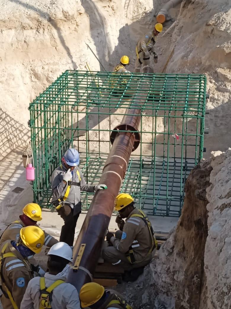
In pipeline engineering, boundary conditions describe how the pipeline interacts with its environment, adjacent equipment, and operational systems. They define how loads are applied, how movement is restrained, and how responses are transmitted through the system.
Common pipeline boundary conditions include:
) Axial, lateral, and vertical soil restraint.
) Support type, spacing, stiffness, and orientation.
) Anchors, guides, stops, and expansion allowances.
) Pressure and temperature limits.
) Hydraulic inlet and outlet constraints.
) Interface conditions at tie-ins, crossings, and facilities.
) Constraints imposed by valves, fittings, and appurtenances.
These conditions are typically idealised to enable analysis. Idealisation is both necessary and unavoidable; however, it introduces an implicit assumption that the defined boundary conditions will exist in reality in approximately the same form.
Unlike pipe diameter, wall thickness, or material grade, many boundary conditions are not intrinsic properties of the pipeline. They are emergent properties of how the pipeline is installed, supported, restrained, commissioned, and operated.
A key distinction often overlooked in pipeline engineering is that boundary conditions are time-dependent. They do not all exist simultaneously at the design stage, nor do they appear instantaneously at commissioning.
Boundary conditions typically evolve across several phases:
) Design definition.
) Construction formation.
) Commissioning stabilisation.
) Operational modification.
At each phase, constraints are added, removed, or altered. The pipeline experiences different load paths, restraint conditions, and deformation states as it progresses through these stages.
Design analyses often represent the final operating condition, but the path taken to reach that condition –including intermediate boundary states – can significantly influence residual stress, deformation, and long-term behaviour.
Design and construction are often treated as sequential activities. While constructability reviews attempt to bridge this gap, many construction-dependent boundary conditions are difficult to define accurately during design.
Several structural features of pipeline projects contribute to this challenge:
) Construction methods are finalised after design freeze.
) Temporary works are developed independently of permanent design.
) Sequencing decisions are driven by schedule, access, and logistics.
) Site conditions evolve during construction.
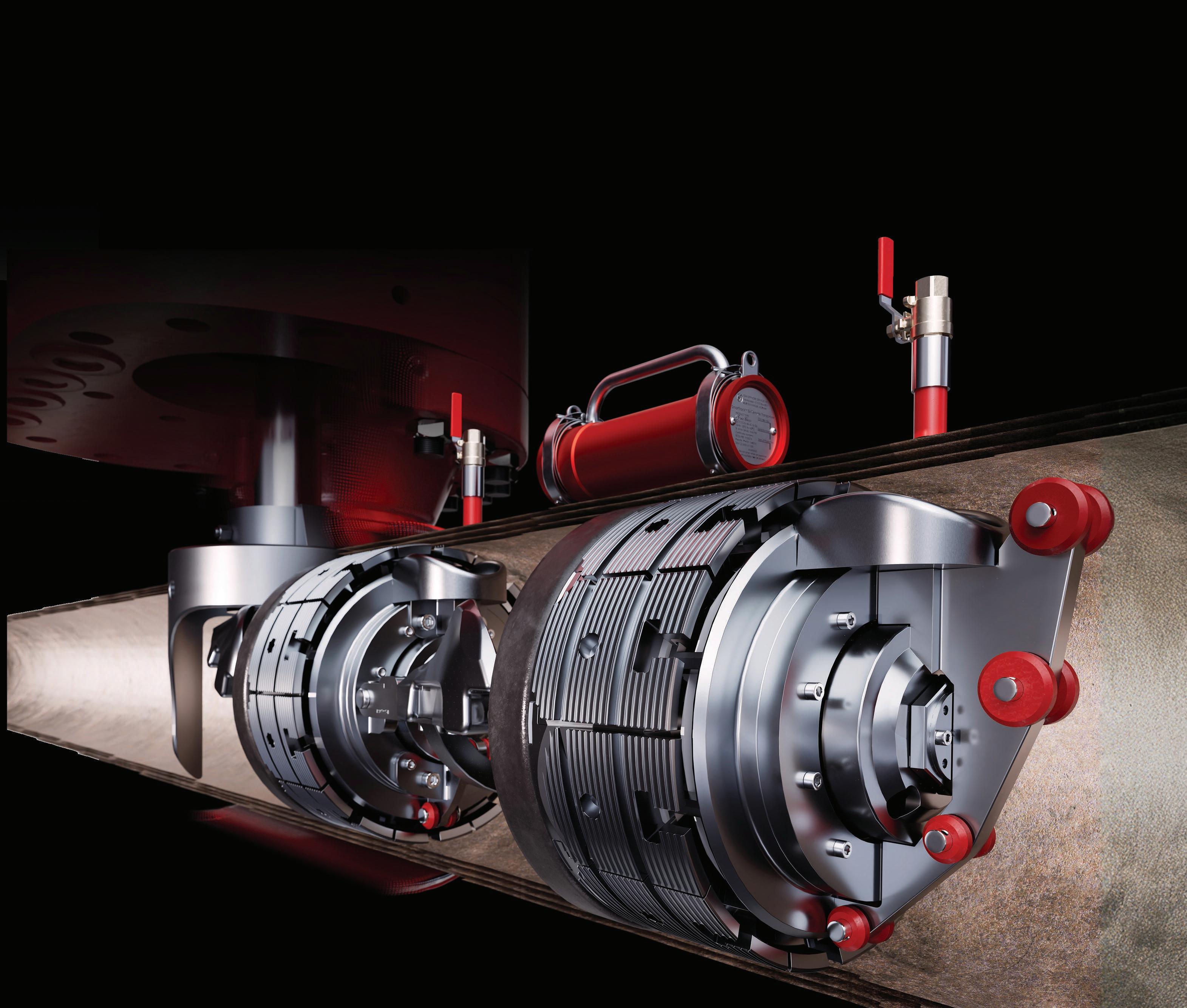
Uncompromising safety. Unmatched throughput.
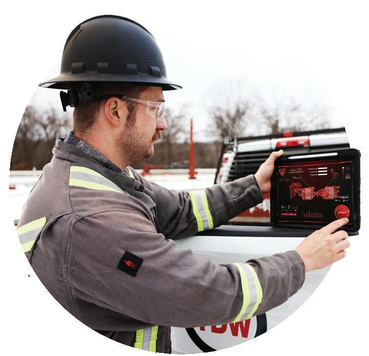
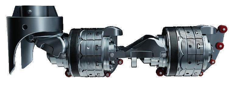
The TDW SHiiELD™ is the safest isolation tool on the market, eliminating emissions with a continuously monitored, leak-proof seal. The integrated bypass reduces flow restrictions, delivering more throughput without additional fittings or hot taps. SHiiELD sets a new industry standard exceeding traditional double block and bleed systems by independently anchoring each pressure boundary ensuring isolation integrity.

See it in action.
tdw.red/SHiiELD
) Field adjustments are made within allowable tolerances.
None of these factors necessarily violate design assumptions individually. However, collectively they can redefine the boundary conditions governing pipeline behaviour.
Soil-pipe interaction in cross-country pipelines
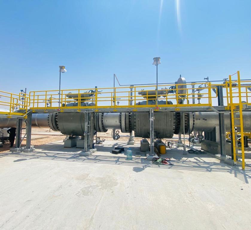
For buried pipelines, soil-pipe interaction is one of the most influential boundary conditions. Design models typically rely on representative soil stiffness values derived from classification tests, assumed compaction levels, and conservative envelopes.
In the field, soil restraint is affected by:
) Variability in backfill material.
) Differences between native soil and imported fill.
) Non-uniform compaction along the route.
) Moisture content and drainage conditions.
) Groundwater presence and fluctuation.
) Seasonal temperature and moisture variation.
) Trench geometry and bedding practices.
These factors influence axial restraint, lateral resistance, and vertical support. As a result, the pipeline’s ability to accommodate thermal expansion, pressure-induced strain, and external movement may differ significantly from design assumptions.
In long cross-country pipelines traversing varied terrain, soil restraint can change dramatically over short distances. Localised reductions in restraint can lead to strain concentration, while locally high restraint can inhibit intended movement and increase stress elsewhere in the system.
Aboveground pipelines and support behaviour
Aboveground and supported pipelines are particularly sensitive to construction-dependent boundary conditions. Supports idealised in design models often exhibit behaviour in the field that differs from assumed conditions.
Construction-related influences include:
) Foundation settlement and variability.
) Grouting, shimming, and levelling practices.
) Fabrication and erection tolerances.
) Support alignment and orientation.
) Installation sequence.
) Differential stiffness between supports.
Temporary supports introduced during construction may inadvertently become permanent constraints. Even when removed, they can influence residual stress states by restraining movement during critical load application phases.
Small changes in support behaviour can shift load paths and stress concentrations, particularly in thermally sensitive systems or pipelines with limited expansion allowance.
Construction tolerances and as-built geometry
Boundary condition Origin Governs Typical consequences in mischaracterised
Soil restraint Construction
Construction tolerances are an inherent aspect of pipeline installation. Horizontal and vertical alignment deviations, weld shrinkage, and fit-up adjustments contribute to as-built geometry that differs slightly from design intent. While these deviations are typically within allowable limits, they can:
Axial/thermal response Strain localisation/buckling
Support stiffness Construction Load paths
Overstress anchors
Tie-in temperature Construction Residual stress Unexpected tensile/ compressive strain
Flange rating Design/interface Pressure envelope Reduced MAOP, surge limits
Valve type
Design/procurement Transients Surge damage
Area classification Regulatoy Allowable stress System pressure
Sequencing Construction Residual loads Early-life integrity issues
Temporary works Construction Restraint Locked-in stresses
Operating philosophy Operations Load spectrum Fatigue, SCC risk
) Introduce unintended curvature.
) Increase local bending stresses.
) Influence fatigue performance.
) Modify support reactions.
) Affect local buckling susceptibility.
Because these effects are distributed and often subtle,

























they are rarely captured explicitly in design analyses. However, they form part of the realised boundary conditions governing pipeline response.
Pipeline systems experience a variety of load states during construction that differ from final operating conditions. These intermediate states can significantly influence residual stress distribution and long-term behaviour.
Examples include:
) Hydrotesting prior to full backfill.
) Tie-ins completed under partial restraint.
) Thermal loads applied before final support installation.
) Differential settlement occurring during staged construction.
) Commissioning activities performed before system stabilisation.
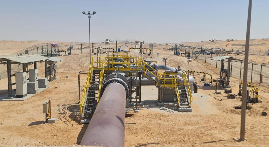
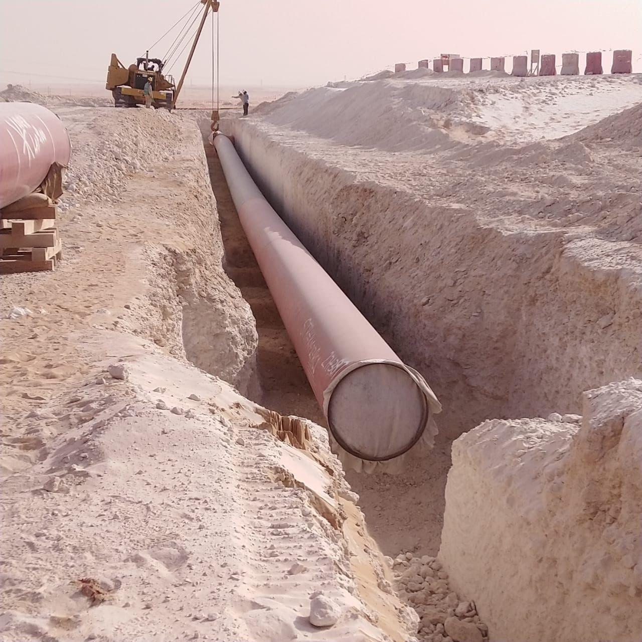
These intermediate conditions may impose load paths not explicitly analysed during design. If not recognised, they can lead to unexpected responses during commissioning or early operation.
Temporary works are often treated as outside the scope of permanent design. However, temporary supports, restraints, anchors, and construction aids can modify boundary conditions in lasting ways.
Examples include:
) Temporary anchors that are not fully released.
) Construction supports that remain in place.
) Temporary backfill with different stiffness characteristics.
) Sequencing constraints that lock in residual stresses.
Recognising temporary works as part of the boundary condition landscape allows engineers to better anticipate system behaviour and manage risk.
In addition to continuous mechanical and geotechnical restraints formed during construction, pipeline systems are also governed by discrete interface and regulatory boundary conditions that often define system-wide limits. Construction-stage tie-in temperature establishes the thermal reference state of the pipeline and can introduce residual stresses that persist into operation. Flange pressuretemperature ratings often impose hard limits on allowable operating envelopes, particularly in mixed-rating systems or interfaces with existing facilities. Valve selection influences both hydraulic and mechanical behaviour, with closure capability defining transient severity and local stiffness affecting load transfer. Area or location classification further constrains allowable stress utilisation and operating pressure based on land use and regulatory requirements. Although these conditions are often treated as local checks, they frequently govern system-level behaviour and should be considered explicitly when assessing pipeline performance across the project lifecycle.
Boundary conditions influence not only mechanical behaviour, but also hydraulic and thermal performance. Support conditions, soil properties, and exposure affect heat dissipation, temperature gradients, and pressure profiles.
In long pipelines, small changes in thermal or hydraulic boundary assumptions can interact with mechanical constraints to produce system-level effects. Integrated consideration of these interactions becomes increasingly important as pipeline systems grow in length and complexity.
Experience across pipeline projects indicates that system response is often more sensitive to boundary condition
variation than to changes in internal parameters such as material strength or operating pressure.
Small changes in axial restraint, support stiffness, or soil behaviour can produce disproportionate changes in stress and strain distribution. This sensitivity explains why pipelines that satisfy design criteria may still exhibit unexpected behaviour once constructed.
The governing uncertainty is frequently located at the interfaces between the pipeline and its environment, rather than within the pipeline itself.
Conventional pipeline stress analyses focus on defined load cases and assumed boundary conditions. While this approach is essential for compliance, it may not fully capture the range of possible system behaviours.
Recognising boundary conditions as variables suggests value in:
) Sensitivity studies focused on restraint assumptions.
) Evaluation of alternate construction sequences.
) Identification of boundary conditions with disproportionate influence.
) Explicit documentation of critical assumptions.
This perspective complements existing methodologies rather than replacing them.
Design-construction collaboration
Projects that actively integrate design and construction perspectives manage boundary condition uncertainty more effectively. Early involvement of construction teams, explicit discussion of sequencing, and recognition of temporary works as part of the system all contribute to improved outcomes.
Feedback loops between site observations and engineering analyses allow assumptions to be revisited before issues escalate.
Boundary conditions established during construction influence long-term integrity. Residual stresses, strain localisation, and restraint patterns affect fatigue life, corrosion behaviour, and response to external loads such as ground movement.
Understanding how boundary conditions develop enables more effective integrity management strategies, targeted inspection planning, and informed lifecycle decision-making.
Mischaracterised boundary conditions increase risk across multiple dimensions:
) Safety risk during construction and commissioning.
) Schedule risk due to rework and delays.
) Cost risk associated with retrofits and mitigation.
) Integrity risk during operation.
Recognising boundary conditions as constructiondependent variables provides a structured way to address these risks proactively.
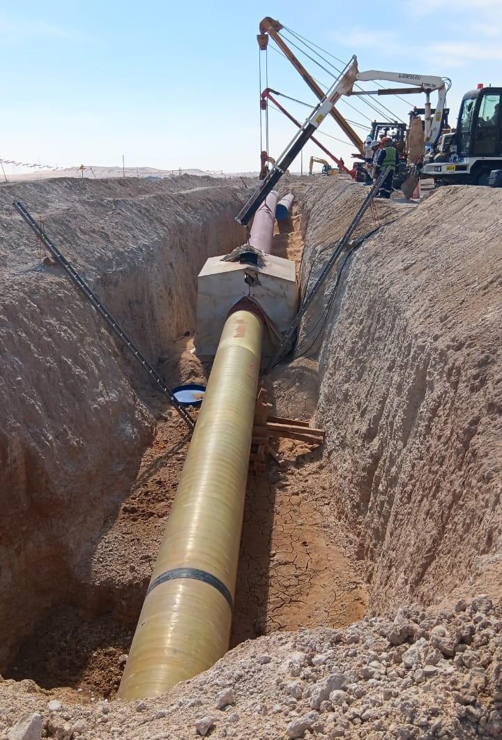
As pipeline routes become longer, terrains more complex, and schedules tighter, the consequences of boundary condition uncertainty increase. Treating boundary conditions as evolving variables encourages engineers to focus on how systems are assembled and constrained, not only on component design.
This perspective supports more resilient project execution and improved long-term performance.
Pipeline challenges encountered during construction and early operation are rarely the result of incorrect calculations. More often, they stem from boundary conditions that evolved differently than assumed during design.
Recognising boundary conditions as constructiondependent variables, rather than fixed inputs, provides a more realistic representation of pipeline behaviour. Incorporating this perspective into pipeline design and project execution improves robustness, reduces rework, enhances safety, and supports long-term reliability.
As pipeline systems continue to increase in scale and complexity, this approach becomes not only beneficial, but necessary for successful project delivery.
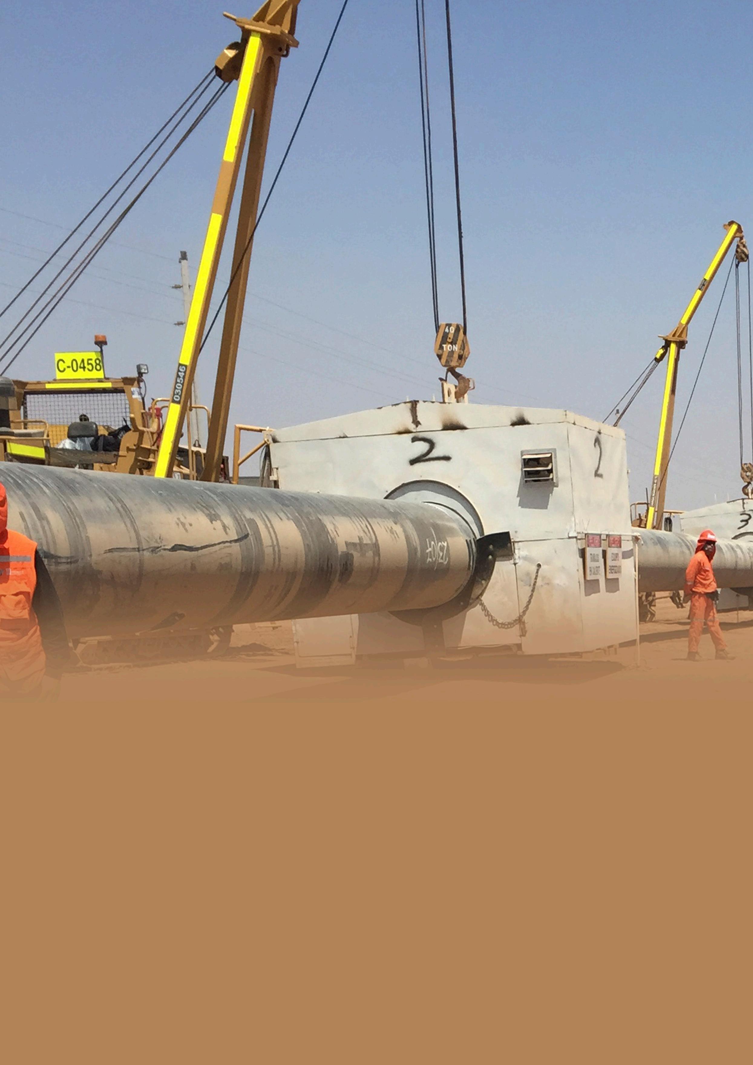
Paul McShane, President EMEAA at CRC Evans, explores the strategic and technical importance of advanced welding technologies in Saudi Arabia’s energy infrastructure transformation under Vision 2030.
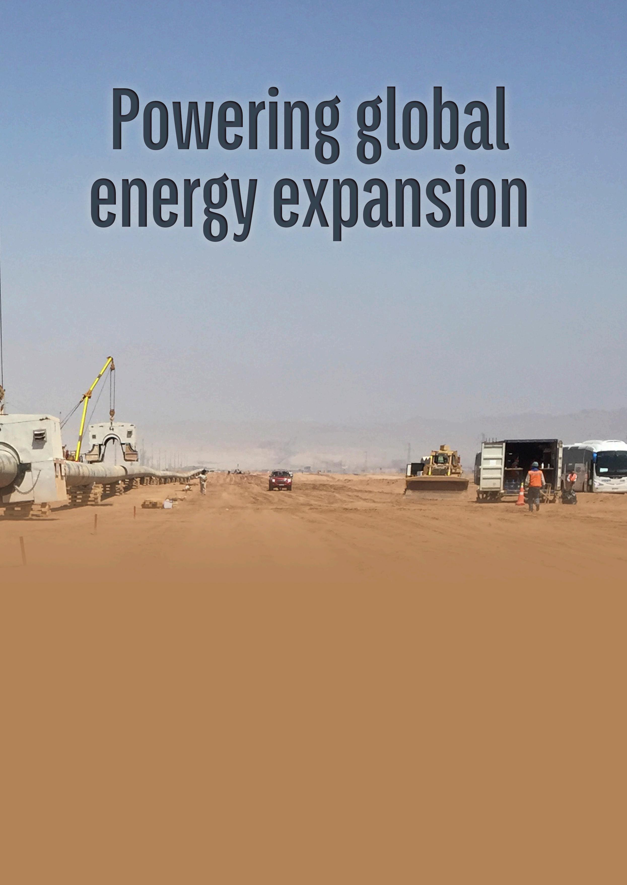
Saudi Arabia is undergoing a profound transformation under Vision 2030, its national strategy to diversify the economy, attract investment, and modernise critical infrastructure. At the heart of this shift lies the Kingdom’s energy sector, not only as an engine of global oil supply, but increasingly as a source of domestic energy security, industrial competitiveness, and sustainable growth.
One of the most important enablers of this transformation is critical energy infrastructure. For instance, by expanding and modernising gas transmission systems, Saudi Arabia aims to reduce its reliance on liquid fuels for power generation, free up more crude oil for export, and provide cleaner, more affordable energy for industries and households alike.
Behind the pipelines, compressor stations, and processing plants that make this vision possible is an often-overlooked engineering sector: welding. Welding and coating are fundamental to building the backbone of the Kingdom’s energy infrastructure, ensuring safety, reliability, and longevity.
Welding and national infrastructure: an overlooked pillar
Despite its low visibility, welding is one of the most indispensable elements of modern energy infrastructure. From oil and gas
pipelines to refineries, LNG terminals, and even desalination plants, virtually every high-pressure system depends on precision welds to maintain integrity and performance.
In pipelines, welding is the link that transforms individual steel segments into continuous arteries of energy supply. The quality of those welds directly affects:
) Safety and structural integrity: poor-quality welds can create vulnerabilities that lead to leaks, ruptures, or catastrophic failures. In contrast, robust welding practices ensure that pipelines withstand pressure fluctuations, temperature extremes, and decades of operation.
) Efficiency of flow: smooth, defect-free welds minimise internal turbulence, reducing energy losses and maintaining throughput efficiency.
) Lifecycle costs: high repair rates or premature failures can add enormous costs over a pipeline’s life. Investing in advanced welding from the outset reduces maintenance requirements and extends service life.
Saudi Arabia’s infrastructure expansion demands rapid execution at scale without compromising safety or durability. This is where advanced welding technologies make a measurable impact. Automated and semi-automated welding systems deliver
consistency across thousands of joints, while innovations such as multi-torch root pass machines increase productivity and reduce the risk of human error.
As the Kingdom accelerates infrastructure growth under Vision 2030, welding excellence is no longer a background concern; it is a strategic enabler of energy reliability and industrial development.
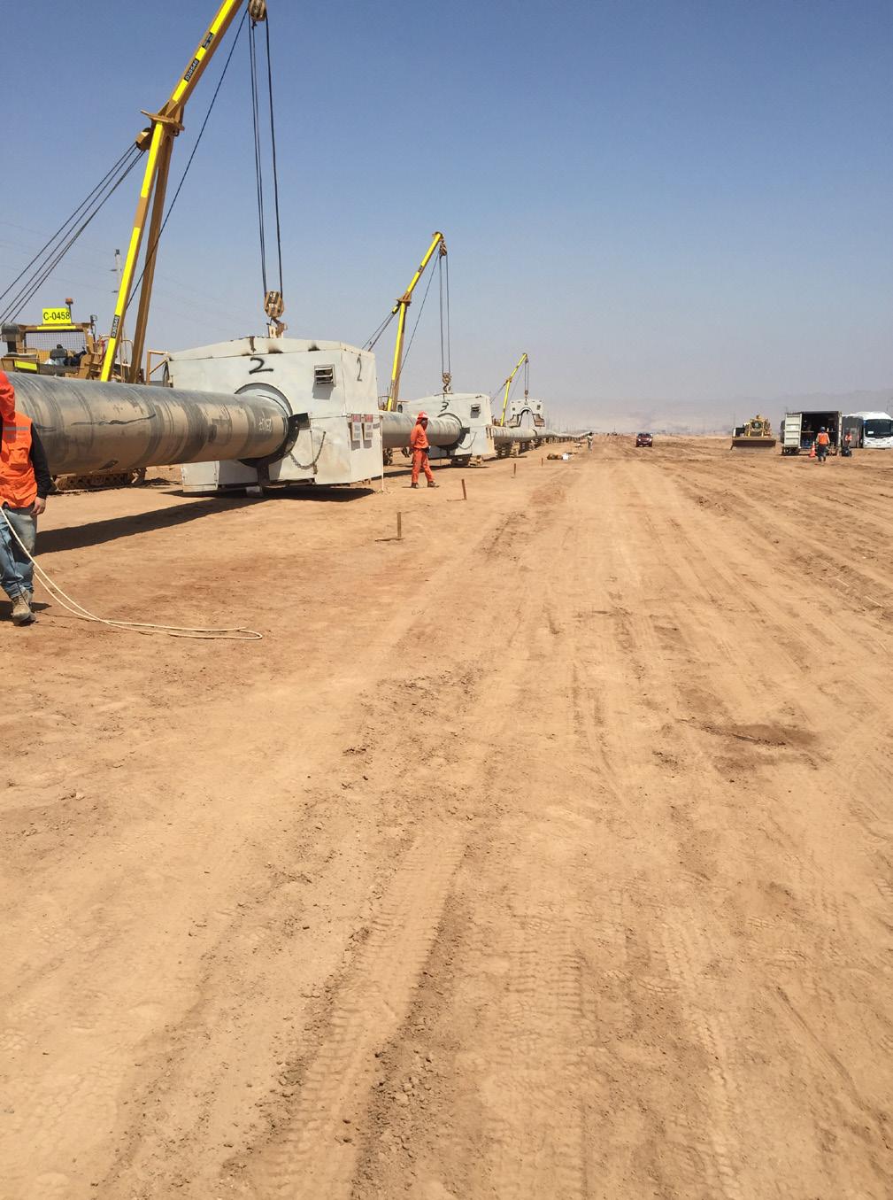
The Master Gas Expansion Phase 3 (MGS III) is one of the most significant infrastructure undertakings in Saudi Arabia’s energy sector. It involves the construction of more than 3970 km of onshore pipeline, including both 56 in. and smaller-diameter pipelines, designed to increase natural gas supply capacity across the Kingdom. The project is central to the national strategy of reducing reliance on liquid fuels for power generation, thereby freeing crude oil for export and supporting a lower-carbon energy mix.
One of the critical technical challenges in MGS III is the welding of large-diameter, high-pressure pipelines under demanding desert conditions. Welding is not only the process that physically joins the pipeline but also the factor that determines its safety, reliability, and operational life. Even slight variations in weld quality can have consequences for efficiency, maintenance requirements, and long-term integrity.
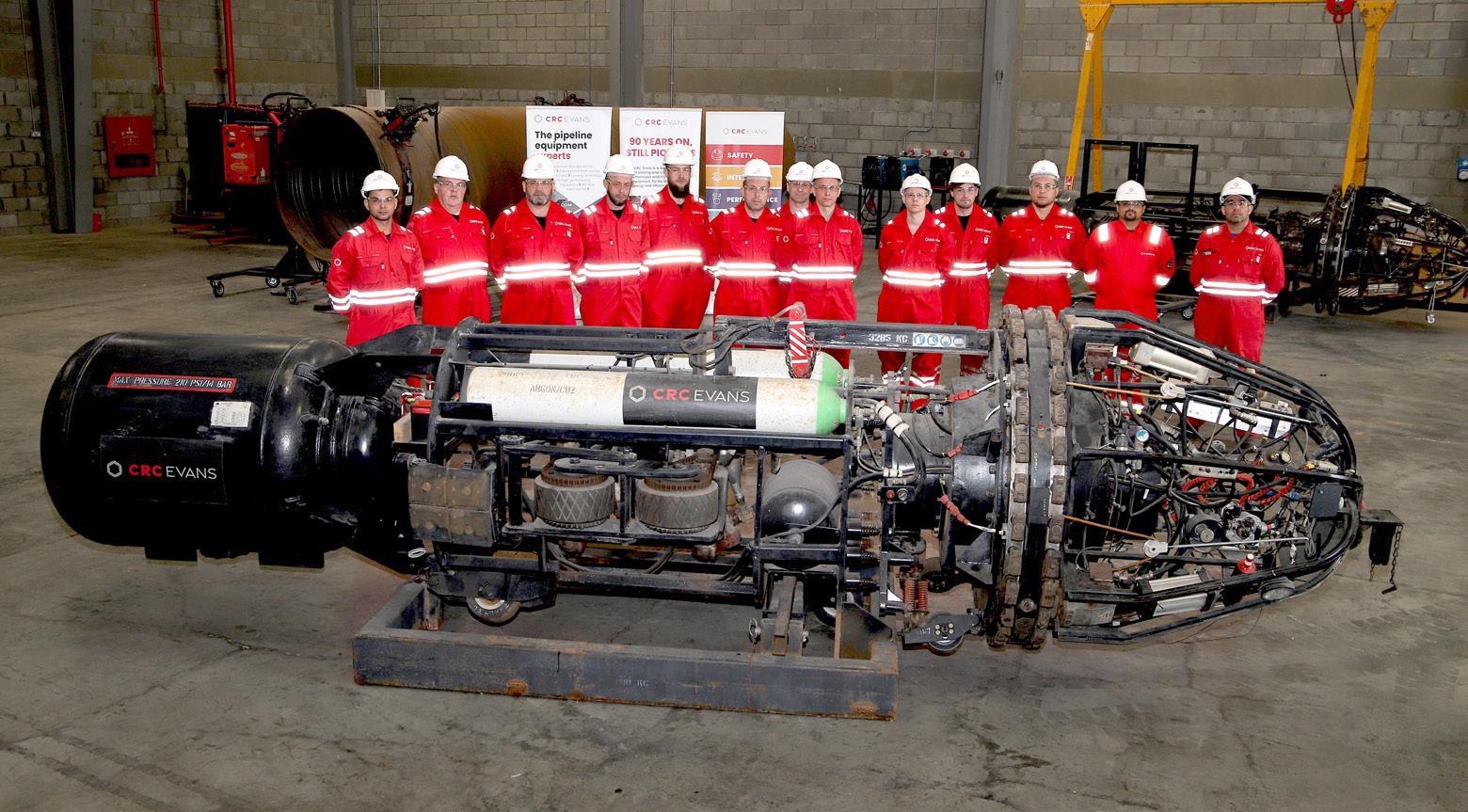
In this context, CRC Evans has deployed its specialised technologies, including internal welding machines (IWMs) with multi-torch root-pass capability. This system allows for the simultaneous operation of multiple torches, producing highly consistent welds and significantly increasing daily welding rates. Following an internal root pass, CRC Evans utilises the P-625 Dual Torch system. This system uses two torches, lead and trail, to allow for dual welding. The torches are independent, with separately programmable movement for each torch. The system supports both vertical tracking and cross-seam/horizontal tracking of the torch head relative to the bevel/profile.
While construction is ongoing within the MGS III, CRC Evans has secured scopes within this pipeline that cover more than 80 000 welds, including procedure qualifications, welder qualifications, and production welding. CRC Evans supports clients from the shack design through right-of-way layout and project management, aiming to enhance efficiency.
For a project of this scale, with thousands of joints to complete, such innovations are vital in meeting schedule demands without compromising quality. CRC Evans provides technical support, welding technicians, and mainline personnel for all aspects of the pipeline.
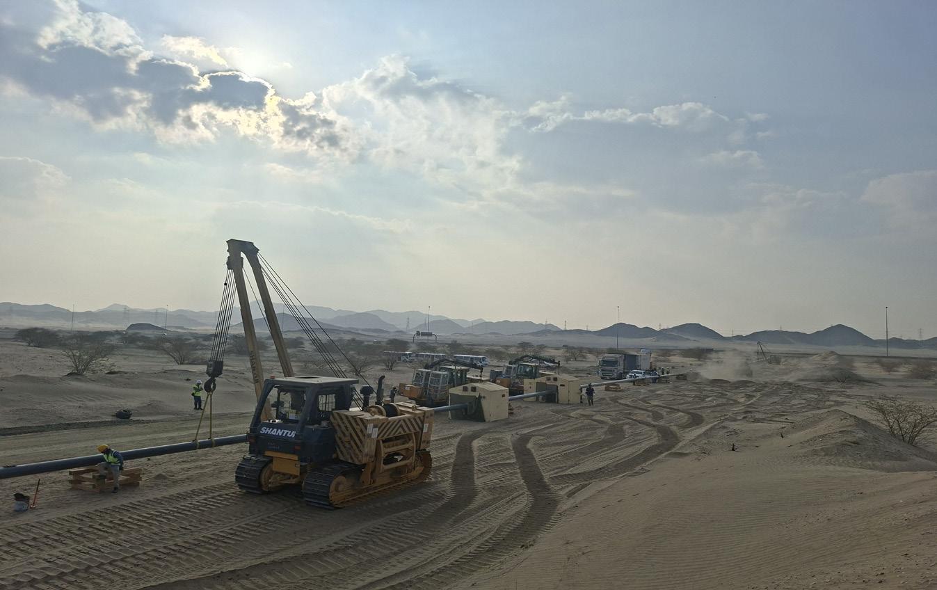
Safety and quality assurance remain the number one priority. On major pipeline projects worldwide, weld repair rates can be a significant source of cost and delay. By employing rigorous QA/QC measures pre-welding, along with post-welding non-destructive testing. MGS III Phase 3 demonstrates how advanced welding practices help maintain low repair rates and high project efficiency. On safety, CRC Evans ensures all its personnel are appropriately equipped for the onsite conditions and remain committed to maintaining its safety procedures and standards.
The project illustrates the strategic role of welding in the development of energy infrastructure. Beyond the technical achievement, it shows how welding excellence contributes to national goals: reliable energy
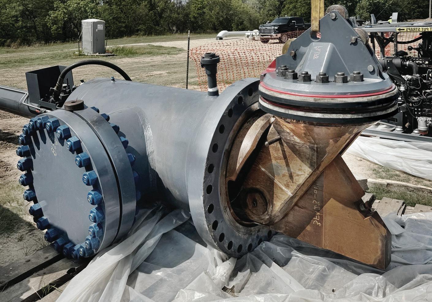
downtime and rework problems DBB equipment with coupled heads or complicated hydraulics can create.
Dually’s compact design features a single, patented dual seal, pivot-style plugging head with all its movement contained within the line stop fitting. The new design ensures more effective chip sweeping functionality by removing more debris that can interfere with a tight seal.
That means Dually is more maneuverable into and out of the pipeline than other DBB systems, and more reliable when it comes to first-time sealing success.
®
delivery, reduced carbon intensity, and infrastructure built to the highest international standards. MGS III Phase 3 is not just about adding pipeline capacity, it is about ensuring that this capacity is constructed to last, enabling Saudi Arabia’s long-term energy ambitions.
Constructing a 56 in. pipeline in desert conditions presents significant technical challenges. Pipes of such scale demand welds with precise alignment, penetration, and heat input control. Variations in any of these parameters can lead to defects that jeopardise the entire system.
The most critical stage is the root pass, where the initial weld establishes the foundation for all subsequent layers. In largediameter pipes, inconsistencies in the root pass can propagate into serious integrity issues. Multi-torch root pass systems, such as CRC Evans’ Internal Root Technology, address this by delivering uniform welds around the circumference with exceptional repeatability. These systems are designed with the capacity to accommodate higher Hi-lo tolerances, while ensuring excellent root transition and smooth bead edges, characteristics that improve coatability and long-term corrosion resistance.
Traditional methods often required copper shoes to control the root bead, introducing risks of inclusions and defects. Advanced internal welding solutions eliminate this step, reducing the chance of trapped impurities. At the same time, using multiple torches lowers overall heat input, which minimises distortion and preserves the metallurgical properties of the steel. By combining lineup and root pass welding in a single system, efficiency improves, and sources of variability are reduced.
Heat management is another vital concern. Excessive heat input can distort the pipe geometry or weaken the steel’s metallurgical properties. Advanced automated welding systems regulate current, voltage, and travel speed with precision, ensuring optimal weld profiles.
Environmental factors also play a role. Desert environments expose welds to high winds, dust, and extreme temperatures, all of
which can compromise quality. Automated welding units provide shielding and process stability that manual methods cannot consistently achieve under such conditions.
Every weld undergoes non-destructive testing (NDT), including radiographic and ultrasonic inspections, to detect defects before the pipeline is commissioned. The result is a repair rate that not only meets but often outperforms industry benchmarks, a crucial advantage on a megaproject where even small percentages of rework can translate into weeks of delay.
In sum, advanced welding technologies matter because they reduce reliance on human variability, enhance productivity, and deliver repeatable quality at scale. For Saudi Arabia’s energy infrastructure, this is the difference between timely, cost-effective delivery and costly setbacks.
The MGS III exemplifies how welding excellence underpins Saudi Arabia’s broader economic and energy goals.
First, it strengthens energy reliability and cost-effectiveness. Phase 3 of the programme is expected to add more than 3.15 billion ft3/d of additional gas capacity to the Kingdom’s network. By unlocking these volumes for power generation and industry, Saudi Arabia can displace significant quantities of diesel and heavy fuel oil currently burned in utilities. This not only lowers the cost of domestic energy but also frees up hundreds of thousands of barrels of crude oil per day for export.1
Second, the project accelerates the transition to cleaner fuels in line with Vision 2030’s sustainability agenda. Natural gas produces around 30 - 40% less carbon dioxide emissions than oil when used for electricity generation. By expanding the gas grid, MGS III supports the Kingdom’s climate commitments while also aligning with wider regional targets, as neighbouring Gulf states face similar challenges in reducing reliance on liquid fuels.
Third, infrastructure megaprojects such as MGS III are drivers of employment and knowledge transfer. Construction requires thousands of skilled and semi-skilled workers, with advanced welding playing a pivotal role. Programmes under In-Kingdom Total Value Add (IKTVA) ensure that Saudi nationals gain training and experience in cutting-edge pipeline technologies, building a workforce capable of sustaining future hydrogen, carbon capture, utilisation, and stoage (CCUS), and water infrastructure projects.
Finally, completing the project to the client’s stringent standards reinforces Saudi Arabia’s reputation as a dependable energy supplier. For the broader Middle East region, this reliability matters: a more flexible and resilient Saudi Arabian gas grid can underpin regional energy trade, support cross-border industrial growth, and stabilise supply amid global market volatility.
While gas pipelines are today’s priority, the future of welding in Saudi Arabia spans a much broader spectrum of opportunities.
The Kingdom’s hydrogen economy roadmap envisions largescale production, transport, and export of hydrogen. Hydrogen pipelines will require new welding techniques to address unique challenges, such as hydrogen embrittlement, and will demand even higher levels of precision and metallurgical control.
Similarly, carbon capture and utilisation infrastructure will involve extensive pipeline networks and high-pressure containment systems, all dependent on advanced welding practices.
In the water sector, Saudi Arabia continues to invest in desalination and water distribution systems, which also rely on robust welded joints for durability under corrosive conditions. Mega-refinery upgrades and petrochemical expansions will further increase demand for cutting-edge welding solutions.
Equally significant is the role of welding in workforce development and localisation. Companies such as CRC Evans are not only deploying automation but also investing heavily in technology knowledge transfer to local communities. By training local welders, operators, and inspectors in modern technologies, it ensures that localisation is not limited to project execution but extends to building long-term capabilities. This approach supports the Kingdom’s vision of developing a highly skilled pipeline of professionals who can sustain its infrastructure ambitions
Looking ahead, intelligent automation, combining robotics, machine learning, and real-time quality monitoring, will become central to welding in the Kingdom. By adopting these innovations early, Saudi Arabia can position itself as a global leader in energy infrastructure construction, with welding as a cornerstone capability.
Welding is far more than a technical trade; it is a strategic enabler of Saudi Arabia’s energy transformation. From safeguarding the integrity of gas pipelines to supporting the development of hydrogen networks and carbon capture infrastructure, welding forms the unseen backbone of the Kingdom’s critical energy systems.
The convergence of advanced technology, global expertise, and rigorous execution is essential to deliver projects at the scale demanded by Vision 2030. The rapid expansion of energy megaprojects, such as the Master Gas Expansion Project, illustrates how advanced welding not only meets immediate construction objectives but also underpins broader national priorities, including energy security, sustainability, and industrial development.
As Saudi Arabia continues to build its energy future, welding will remain a vital foundation, silent yet precise, technical yet strategic, and indispensable to the Kingdom’s long-term progress.
Reference


September 21-24, 2026 | BMO Centre, Calgary, Canada
The World’s Pipeline Industry Meets Here
Organized by:
Attendees
1,300+
8,000+ Delegates
300+
Exhibitors
300+
Expert Speakers
20
80+ hours of networking

Countries Attending Registration









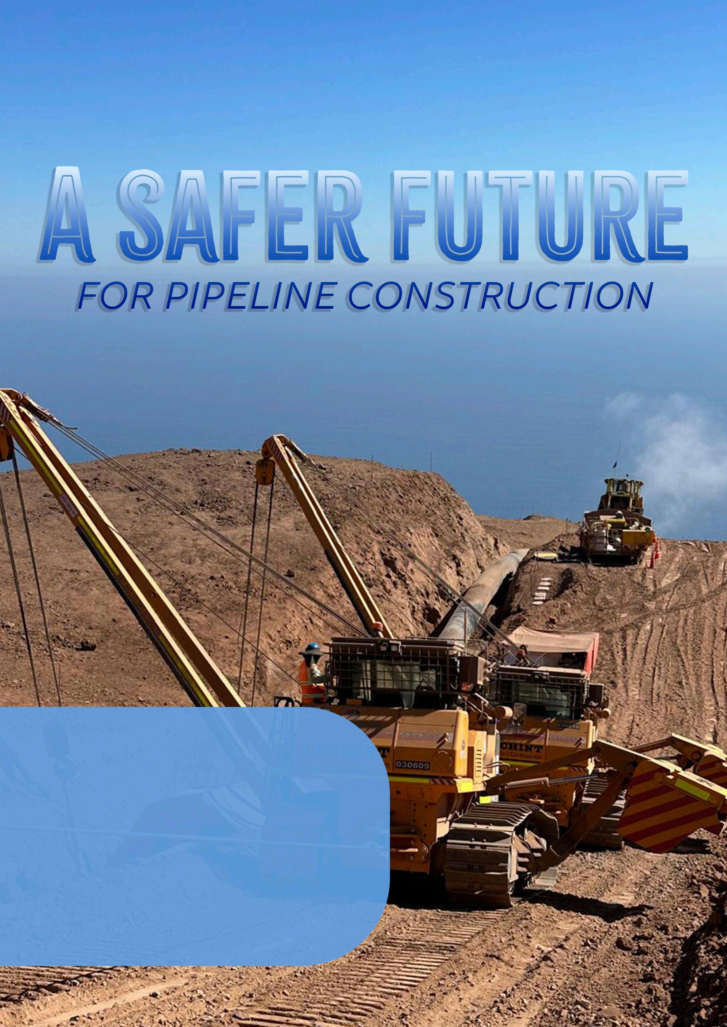
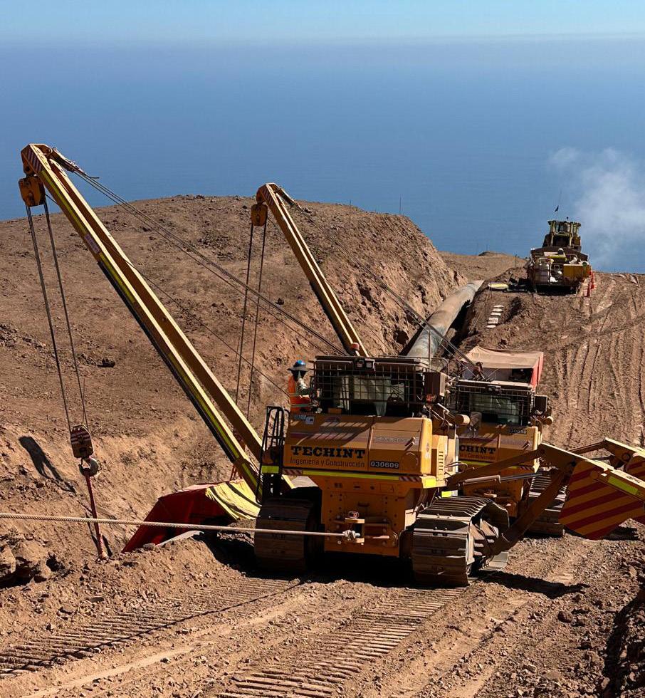
Etienne P., SCAIP S.p.A., explains how SCAIP’s SPX pipelayers combine heavy-duty engineering with advanced safety, monitoring, and communication technologies to make modern pipeline construction safer, more precise, and better coordinated.
Pipeline construction is one of the most demanding industrial environments in the world, requiring absolute coordination among operators, supervisors, engineers, and heavy machinery. What was once a worksite dominated by brute force has evolved into a highly specialised operational
environment where safety, precision, and reliability must coexist seamlessly. As global pipeline projects expand into remote and challenging regions – from the deserts of the Middle East to the rugged slopes of South America and the frozen ground of Canada and Alaska – the role of the pipelayer has become more essential than ever. It is no longer enough for these machines to lift and position massive pipe sections; they must do so in a way that actively prevents accidents, improves communication, and enhances the decision-making ability of the crew.
For more than 60 years, SCAIP has dedicated itself to the design and development of machinery that meets these expectations. The company’s roots stretch back to the late 1950s when Franco Grassi began his mechanical workshop in Parma. In those early years, SCAIP built its expertise by repairing and overhauling
tracked tractors and construction equipment produced by major manufacturers. Soon after, a partnership with a leading Italian pipeline company transformed the organisation, steering it firmly into the specialised world of pipeline machinery. From those beginnings emerged an engineering philosophy that guides SCAIP to this day: machines should be intuitive, durable, and above all, safe.
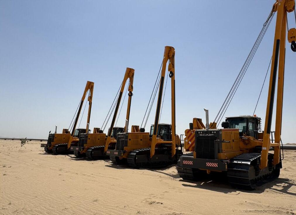
This philosophy is fully expressed in the SPX Series of pipelayers – a range developed to meet modern demands with the latest safety and hydraulic technologies available. Since their official introduction in 2007, SCAIP’s SPX pipelayers have been deployed worldwide, appreciated as much for their stability and lifting performance as for their sophisticated safety systems. They represent a convergence of mechanical robustness and intelligent control, combining high-capacity lifting capability with an operator environment designed to reduce risks and enhance awareness.
Safety begins where information begins, and SCAIP has equipped every SPX pipelayer with a full-colour LCD display that provides the operator with real-time data about the machine’s working conditions. This is not merely a panel of gauges but a central information hub that continuously reports hoisted weight, boom angle, operational limits, slope angles, and the status of all major safety systems. In an industry where operator decisions can affect dozens of personnel in the immediate vicinity, the importance of a clear, precise, and constantly updated view of the lift cannot be overstated. The LCD panel becomes an extra set of eyes – one that never fatigues, never overlooks changes, and never stops monitoring conditions.
The SPX Series integrates several advanced electronic safeguards that work together to reduce human error and anticipate potential hazards before they escalate. Among the most significant of these is the ATP system, a highly responsive antitipping technology that observes the machine’s centre of gravity, load position, and operational configuration at all times. Should the pipelayer approach a situation where tipping becomes likely –perhaps due to excessive load, uneven ground, or an unsafe boom position – the ATP system immediately alerts the operator and advises corrective actions. By intervening early, it helps prevent precisely the sort of incidents that have historically caused serious injuries and project delays.
Complementing ATP is the LAS system, a longitudinal slope monitoring solution that delivers continuous information about the machine’s inclination. Pipeline rights-of-way are rarely level; they often traverse complex terrain that challenges even the most experienced operators. When lifting heavy pipe sections, a small increase in slope angle can dramatically alter the machine’s stability profile. The LAS system provides accurate and immediate warnings when slope conditions become unsafe for lifting operations, allowing operators to halt the lift or adjust positioning before risk develops. Together, ATP and LAS form a dual safety net that elevates the operator’s awareness beyond what is physically visible. Another important system that enhances both safety and machine longevity is SCAIP’s anti-two-block technology, which prevents the hook block from striking the boom tip block – a dangerous event known to cause cable failures, structural damage, and potential injury. The SPX machines automatically enforce a
minimum safe distance between these components, intervening if the operator inadvertently brings them too close. Similarly, the boom kick-out system prevents the boom from being overlifted into unsafe angles, protecting both the machine’s structural integrity and the stability of the lift.
These systems work in harmony to support operators, but SCAIP has not limited its safety innovations to the cab alone. One of the company’s most distinctive contributions to modern pipelaying is the external ‘traffic-light’ style visual indicator system – a simple yet extraordinarily effective communication tool for laying supervisors and ground crew. The concept is straightforward: a highly visible light mounted externally on the machine displays green, yellow, or red to indicate the pipelayer’s safety status. When conditions are normal, the supervisor sees green. As the machine approaches its operational limits, yellow appears. And if the machine reaches the rated lifting capacity, the system displays red, stopping immediately some of the functions.
This colour-coded communication assists supervisors in coordinating multiple pipelayers simultaneously, especially during challenging operations such as lowering-in large-diameter pipelines where several machines must work together. Rather than relying solely on radio communication or experience-based judgment, supervisors can visually confirm machine status from a distance, even in noisy environments or low-visibility conditions. It is a highly efficient method of communication that enhances situational awareness across the entire team.
Inside the cab, operators benefit from a suite of controls designed for precision and ease of use. SCAIP has streamlined its interface so that a single joystick manages both winches and engine throttle, allowing operators to perform complex lifting movements with minimal physical effort. Travel is controlled by a separate joystick, enabling highly accurate positioning even on difficult terrain. Additional pilot levers provide fine adjustment capability, making it easier to align and manipulate pipes without overcorrection. This thoughtful combination of ergonomic design and control responsiveness allows operators to focus on safety and positioning rather than struggling with machine mechanics.
Most recently, the company supplied one model with a remote control that allows to control all machine functions (winches included). The operator can drive the machine from the ground in a very safe and easy way. This is an experiment to understand how far we can go in working without the operator on board.
Underneath these systems lies the robust mechanical engineering that has long been SCAIP’s hallmark. The SPX Series utilises hydrostatic transmissions for smooth and predictable power delivery, high-torque final drives for challenging terrain, and hydraulically powered winches engineered for endurance and precision. Quick-disassembly counterweights (QD-CS) simplify transportation logistics, reducing downtime between job sites and improving fleet mobility. Heavy-duty booms, pivot pins, and protective structures (including optional enclosed cabins with heating and air conditioning) reinforce durability and operator safety even in harsh environments.
Together, these features give SCAIP’s pipelayers the unique ability to support safe lifting as an active process rather than a
passive set of precautions. The goal is not simply to prevent failure but to create a machine that encourages safer habits and delivers better feedback to the team. In an industry where multiple pipelayers often work in tandem, coordination is everything. When operators are fully informed by real-time data and supervisors can visually confirm machine behaviour at a glance, the risk of miscommunication drops significantly. This contributes to a more confident work environment – one where operators spend less time questioning machine limits and more time focusing on precision and situational awareness.
The SPX Series includes several models ranging from compact 26 t units to powerful 97 t machines capable of supporting largediameter pipeline installations. Though each model differs in lifting capacity, they all share the same safety systems, control philosophy, and diagnostics platform. This consistency is invaluable for contractors who operate multiple machines on the same project. Training becomes more efficient, operators move easily between models, and supervisors benefit from standardised communication tools across the fleet.
Over the year, SCAIP followed the market request in terms of transportability, designing different models of big size pipelayer (80 t and 90 t), that can be disassembled and fit into two containers, or where the overall width can be narrowed under 3 m (117 in.).
As pipeline construction evolves, regulatory environments have become stricter and expectations for safe operating practices have increased accordingly. Clients and contractors alike now demand equipment that reduces risks not only through structural strength but also through intelligent design. SCAIP’s SPX pipelayers meet these expectations by combining mechanical robustness with digital precision, delivering a platform where safety and efficiency reinforce each other rather than compete.
With greater emphasis placed on environmental responsibility, project timelines, and workforce well-being, the SPX Series represents more than just an incremental improvement – it represents a shift toward a more proactive, technology-driven approach to pipeline lifting operations. By giving operators the information they need the moment they need it, and by giving supervisors a clear and unambiguous view of machine status across the right-of-way, SCAIP has redefined what modern pipelaying machinery can contribute to jobsite culture.
From its origins as a small mechanical workshop in Parma to its current role as a global manufacturer of specialised pipeline machinery, SCAIP has retained its dedication to building machines that are both powerful and protective. The SPX Series is the culmination of decades of experience, innovation, and fieldproven engineering. In an industry where the margin for error is small and the consequences significant, SCAIP has chosen to meet the challenge not with complexity for its own sake, but with technology that supports real people doing demanding work.
In the SPX Series, the company has created machines that not only lift pipe but elevate the entire standard of pipeline safety –one careful lift, one informed operator, and one well-coordinated team at a time.
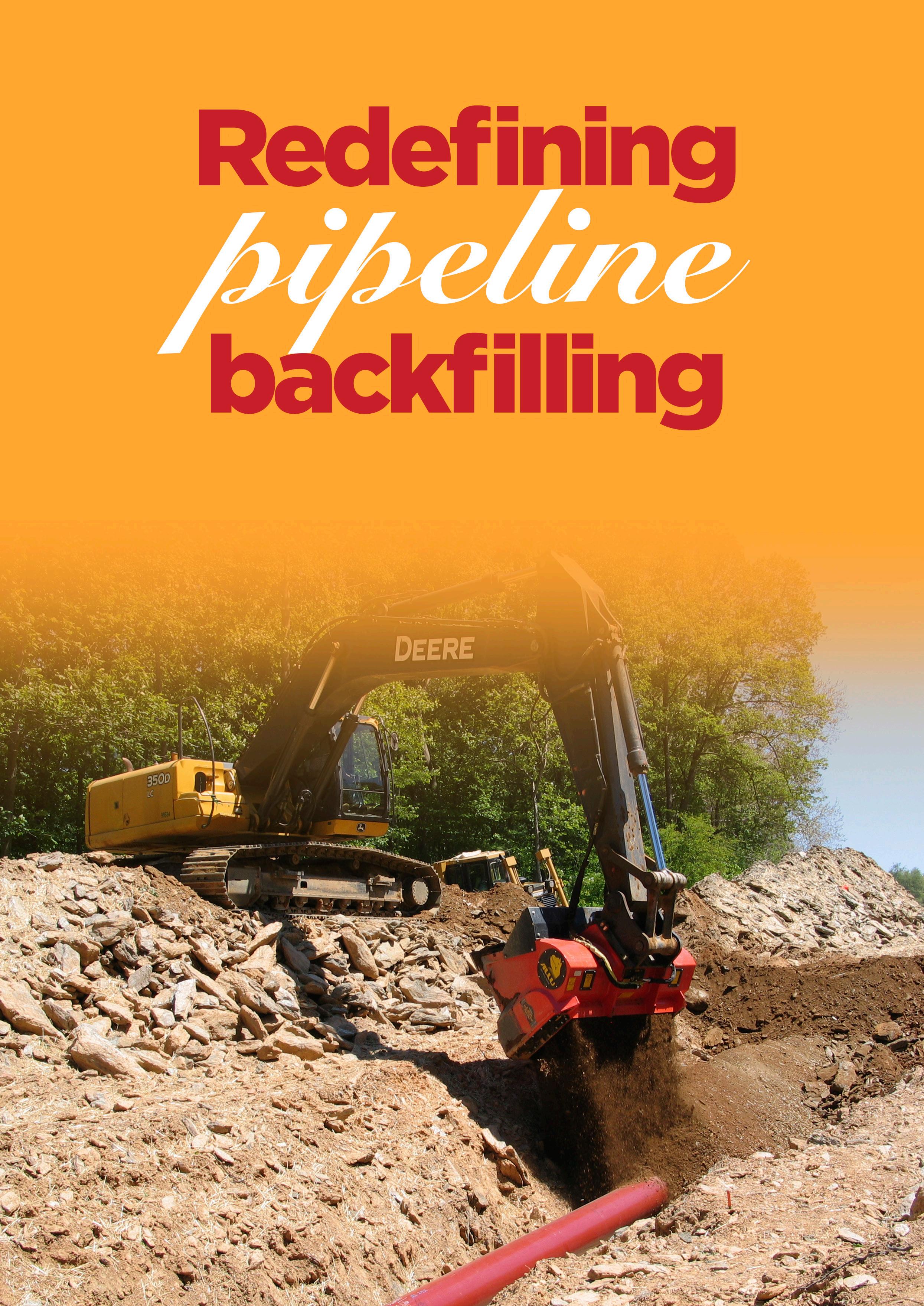
Maimee Henderson, ALLU, USA, discusses how on-site screening with ALLU buckets is redefining pipeline backfilling.
Pipeline construction requires teams to analyse costs while balancing productivity with regulatory requirements. Among all the stages required to install a safe, high-performing pipeline, padding and backfilling have traditionally been viewed as routine tasks. Yet in the last decade, this phase has undergone a re-evaluation. Owners, contractors, and regulators increasingly recognise that properly sourced and installed padding influences installation speed, long-term integrity, and overall cost.
In today’s construction environment, imported padding material has become more expensive and less predictable. Hauling, stockpiling, and sourcing challenges add complexity, especially in remote regions. Environmental expectations
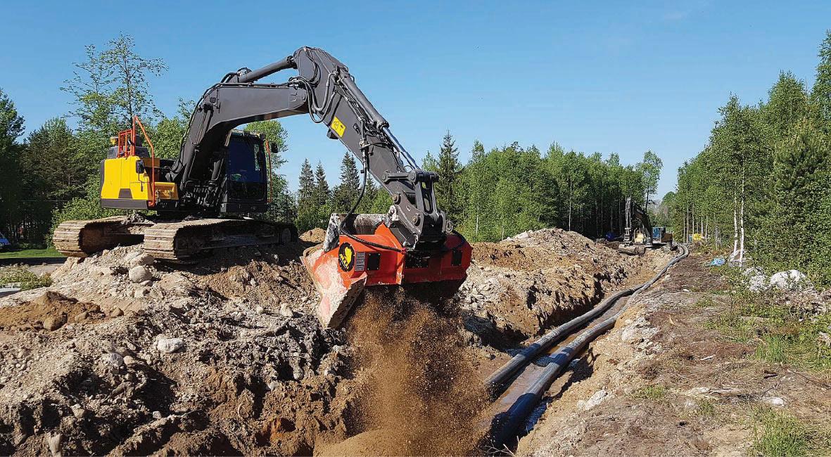
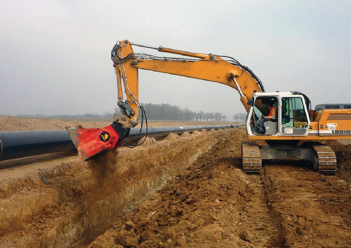
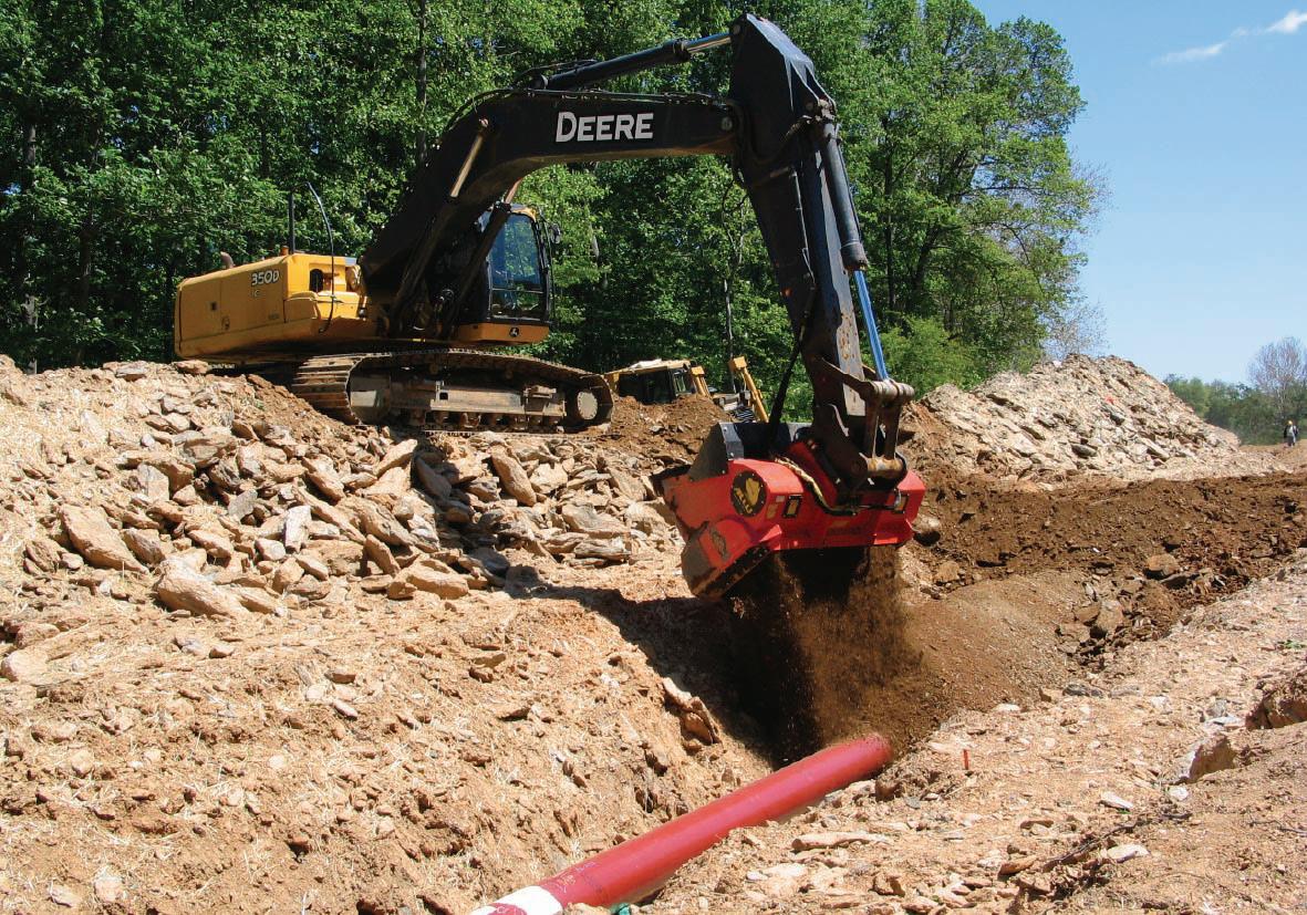
have also risen, and trucking thousands of cubic yards of material now conflicts with sustainability goals. As a result, the industry is seeking better ways to control material production and reduce reliance on external suppliers.
This is where ALLU’s on-site material processing approach is reshaping pipeline workflows. The ALLU Screening Bucket enables efficient processing during the backfilling phase, allowing contractors to achieve the required particle-size distribution directly at the trench. Rather than treating excavated soil as a waste burden, the system turns on-site material into a resource ready for immediate use.
Padding and backfilling influence material quality, coating protection, settlement performance, and overall construction cost. Natural soils often contain clumps, stones, and inconsistencies that make them unsuitable without processing. Teams therefore rely on imported engineered fill, which introduces cost volatility, haul logistics, and delays tied to aggregate availability.
This traditional approach requires additional machines, operators, staging areas, and truck traffic. In environmentally sensitive areas, these factors complicate compliance and minimise opportunities for reuse. With growing scrutiny on emissions and waste reduction, the industry increasingly sees traditional padding methods as misaligned with modern expectations.
ALLU screening and crushing buckets address these challenges directly. By attaching to excavators, wheel loaders, or backhoes, the bucket transforms the carrier into a processor capable of screening, crushing, and separating material in one step.
Excavated soil enters the bucket and passes through rotating blades that break down lumps and oversized particles. This results in fine, uniform outputs that meet padding specifications and can be placed directly back into the trench. This continuous workflow eliminates dependence on off-site processors or imported aggregates.
Case studies show projects achieving cost reductions as high as 80%/yd3 when using on-site screening instead of imported material. These savings stem from reduced trucking, lower fuel use, fewer operators, and improved schedule predictability. Environmental benefits follow naturally from reduced haul distances and minimised disturbance.
ALLU technology integrates naturally into pipeline construction. As the trench is excavated, spoil becomes the raw material source. The bucket processes this material immediately, producing uniform padding ready
for placement. This creates a self-sustaining cycle that reduces delays and improves crew coordination.
With fewer machines and less traffic in the corridor, the right-of-way becomes safer and more efficient. Material quality improves when teams control the processing themselves, on-site. Owners appreciate the reduced risk of coating damage and settlement issues, and inspectors see more consistent results across the project.
Remote projects experience some of the greatest benefits. Where aggregate sources are limited or distant, traditional padding workflows can result in massive hauling costs and schedule disruptions. With ALLU, the trench becomes the material supply, making the operation largely independent of outside constraints.
Examples from the field: proven results in real conditions
One pipeline team achieved an 80% reduction in padding cost by processing trench spoil directly with an ALLU screening bucket. The reduction in hauling reshaped the project budget and improved workflow consistency.
Another example from Arizona demonstrates the system’s precision. A utility contractor used an ALLU DN 3-12 with TS08 blades to generate 3/8 in. minus bedding material. The screened output met specifications on the first pass and was placed directly into the trench, eliminating dependence on external suppliers and keeping the crew on schedule.
These outcomes reflect a broader industry trend: teams value solutions that give them more control over material quality, cost, and production speed.
On-site screening provides strategic advantages beyond daily production. Companies gain predictable padding costs, reducing exposure to fluctuating aggregate prices and transportation constraints. This stability improves bid accuracy and project planning.
Owners benefit from enhanced quality assurance. Consistent, fine padding protects pipe coatings more reliably, reducing long-term maintenance risks. Sustainability targets are easier to meet when emissions and disturbances decline. The approach aligns well with
industry-wide goals for responsible, resource-efficient construction.
Successful adoption of ALLU technology begins with understanding soil characteristics such as moisture, clay content, and particle distribution. These factors help determine the appropriate screening or crushing configuration.
Matching the bucket to the correct carrier machine ensures optimal throughput and efficiency. Proper site layout enhances workflow, and operator training ensures consistent, high-quality output. ALLU’s dealers and support teams assist

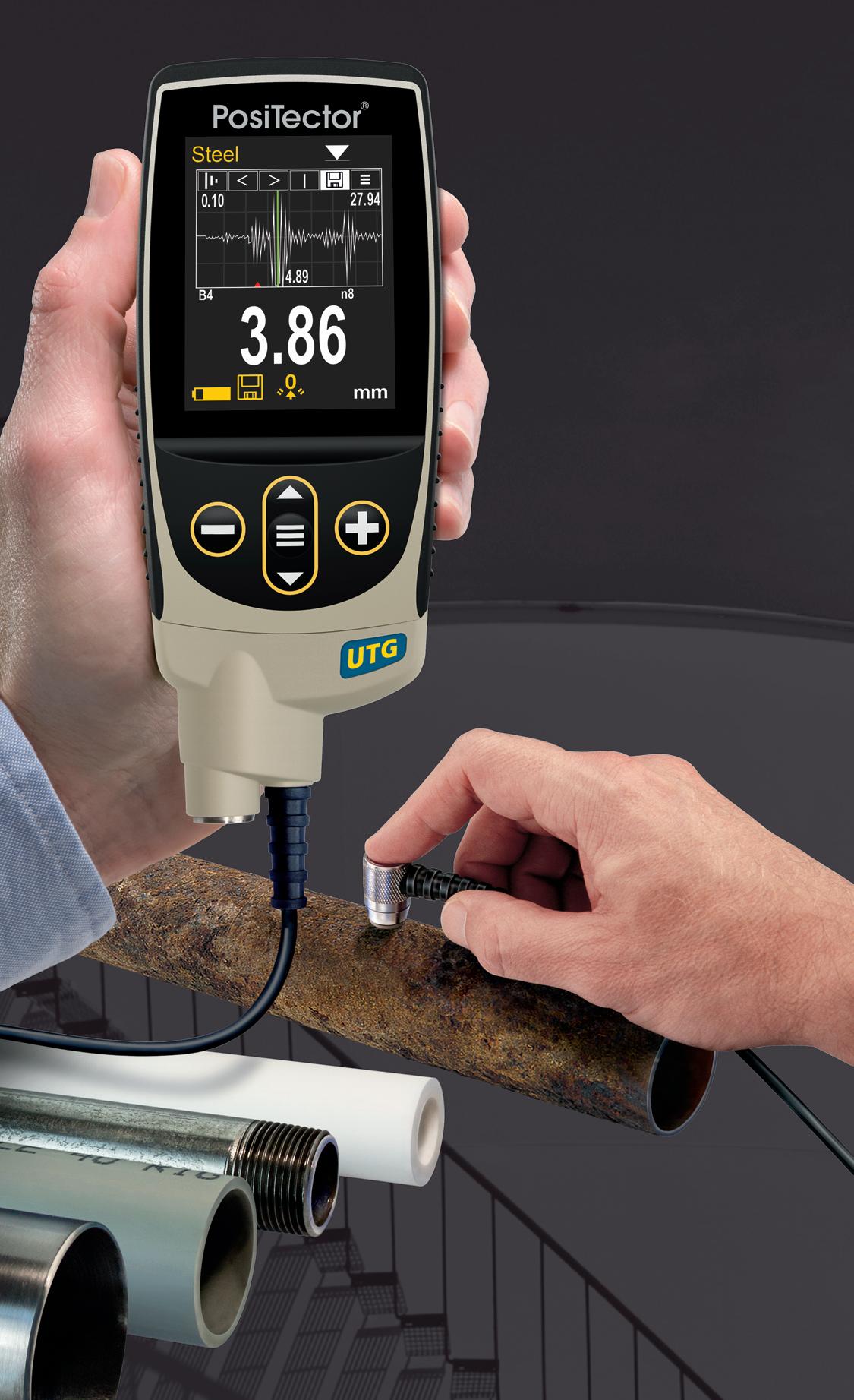
Ideal for measuring the remaining wall thickness and the effects of corrosion or erosion on tanks, pipes, or any structure
n 6 Models available including Corrosion, Xtreme, Multiple-Echo, Low Frequency, and Precision
n All models include Min Scan mode, memory, statistics, and USB
n Advanced models include: A-Scan, B-Scan, Bluetooth, and WiFi
n Weatherproof, dustproof, and waterresistant—IP65-rated enclosure
Scan here to learn more

PosiTector UTG M features Thru-Paint capability to quickly and accurately measure the metal thickness of a painted structure without removing the coating.
PosiTector gauge body accepts ALL ultrasonic wall thickness, coating thickness, surface profile, environmental, soluble salt, gloss, and hardness probes manufactured since 2012.
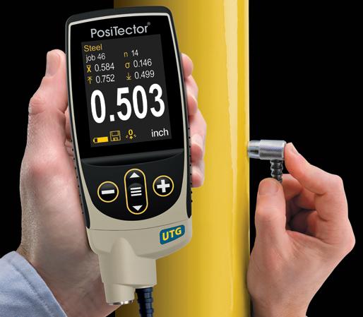


+1-315-393-4450 n 1-800-448-3835 techsale@defelsko.com n www.defelsko.com


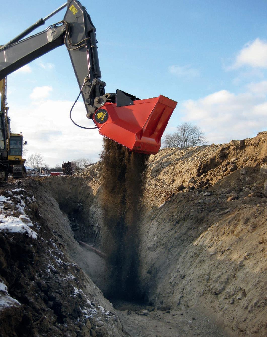
with setup, training, and operational best practices to maximise value.
The industry is steadily shifting away from the traditional ‘import and place’ method. On-site screening aligns with modern expectations for efficiency, environmental responsibility, and cost control. Producing engineered padding at the trench simplifies logistics, reduces emissions, and minimises equipment footprints. With demonstrated success across varied projects, this approach is poised to become a new standard.
Pipeline padding and backfilling influence construction speed, cost, and long-term integrity. Traditional material sourcing introduces risks and inefficiencies that no longer match the industry’s priorities. ALLU’s onestep on-site screening solution offers teams a way to produce consistent, high-quality padding while reducing environmental impact and improving economic performance.
By transforming excavated soil into engineered padding, companies gain control, predictability, and efficiency. As the industry moves toward sustainable and resource-efficient practices, ALLU technology is helping reshape pipeline construction, one trench at a time.
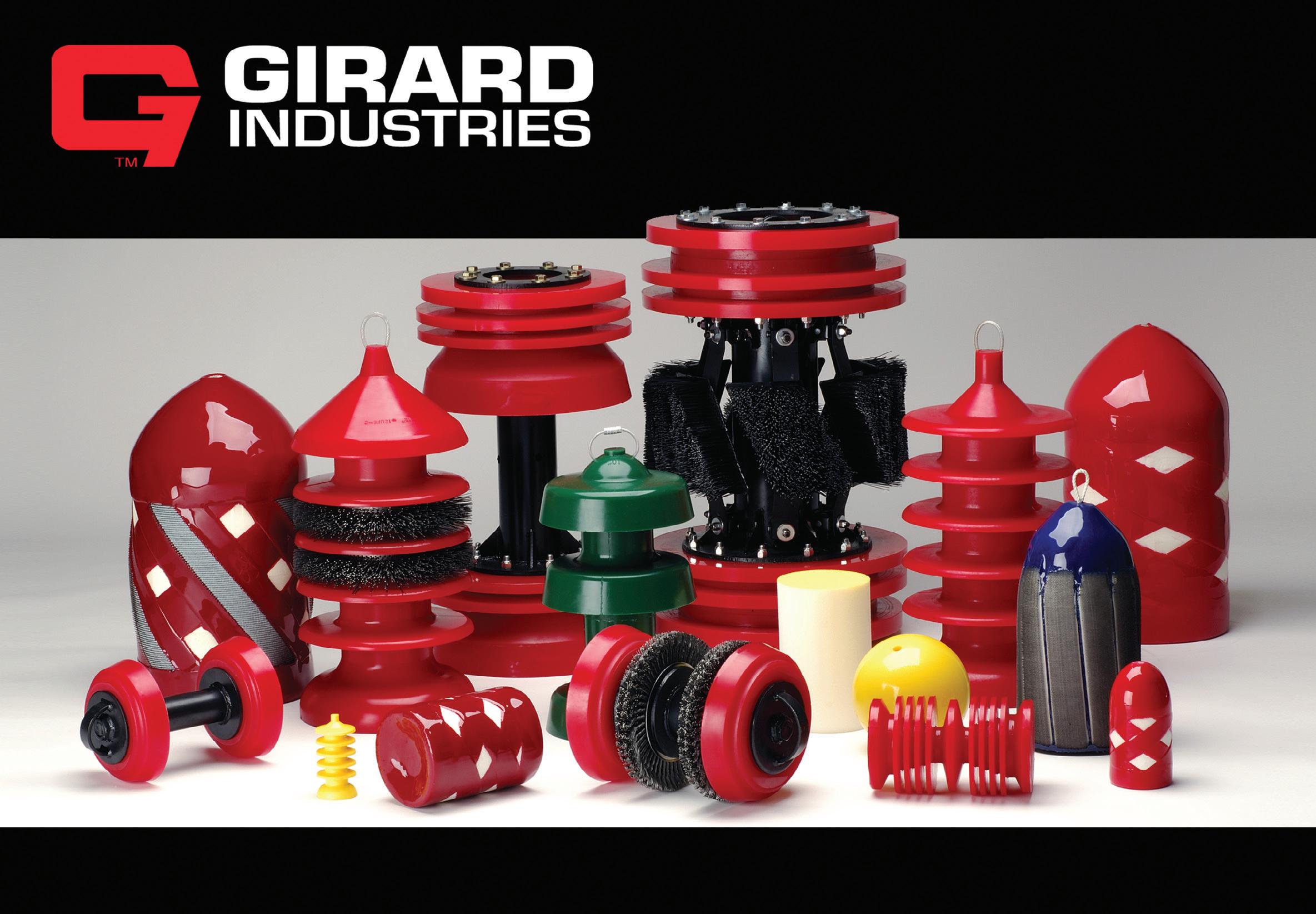

Nicolaas Ainsworth, Argus Machine Co. Ltd (Argus), discusses barrel traps and pigging valves, explaining where each works best, and why.
Operators use pipeline pigs to clean, batch, dewater, and inspect lines, with pig launchers and receivers as the core equipment for launching and retrieving those pigs.1 Two common launcher/receiver systems are barrel traps and pigging valves. Both accomplish the same objective, but with fundamentally different constructs that lead to distinct practices and best use cases. This article will explore those practices, and differences, to derive where each thrives and where each is weaker.
Barrel traps are often considered the conventional system for launching and receiving pipeline pigs as they have been widely used for decades.1 A typical barrel-trap station is built around a cylindrical vessel (the barrel) consisting of a major barrel, a reducer, a minor barrel nominally sized to the mainline pipe, and a closure for loading and unloading pigs.2 The trap also includes branch connections,
piping, and valves/nozzles such as vent, drain, kicker, and pressure equalising connections that connect the trap to the mainline and support launching and receiving operations.2 In simple terms, barrel traps are an isolated side chamber connected to the mainline that operators can isolate and load/ unload pigs into.
Barrel trap operation
The operation of a barrel trap relies on the line pressure to move pigs in and out of the previously noted isolated chamber (or barrel). Exact steps and sequences vary depending on operating conditions, standards, codes, product-specific designs, pig types, and other variables; however, while there is not necessarily a universal SOP, there are some common steps for operating barrel traps found in most designs.3,4 The following sections outline the general phases a barrel
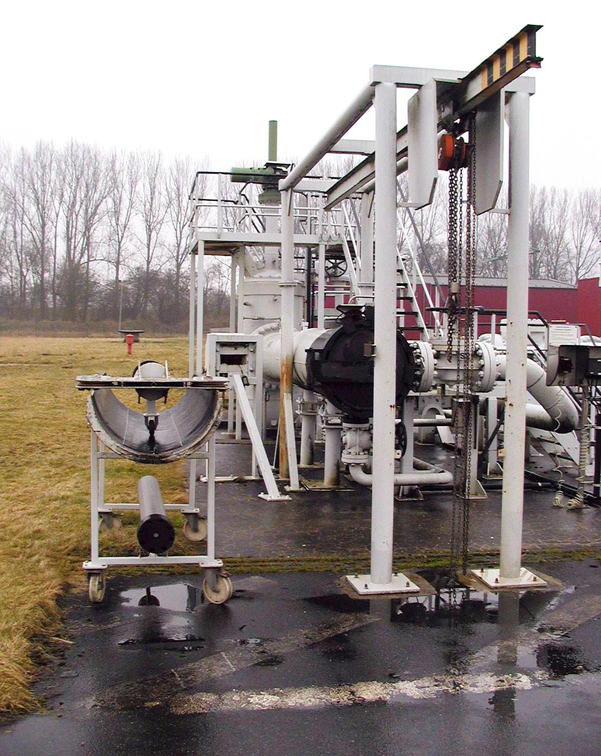
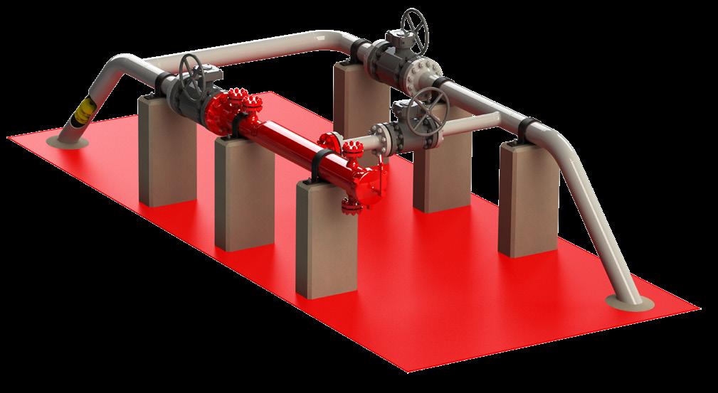
trap undergoes during its launch and receipt operations, respectively.
Barrel trap launching sequence
The objective of barrel trap launching operations is pig insertion. These four phases outline how operators send pigs inline using a barrel trap launcher.
) Isolate and make safe: the trap is first isolated from the mainline and then brought to a safe condition for opening by depressurization (gases) and/or draining (liquids) from the chamber.4
) Load and secure: with the trap at safe pressure, the closure is opened, and the pig is loaded into the main barrel, typically pushed nose-first all the way up against the reducer. The closure is closed and secured.4
) Pressurise and equalise: once the closure is secured, the trap is slowly refilled from the mainline and equalised to the same pressure as that mainline. During filling/equalising, trapped air is also removed from the trap through vent nozzles.4
) Establish flow behind the pig and launch: a pressure differential is then created using kicker/bypasses that push the pig through the major barrel, reducer, and the minor barrel, and into the mainline. Pig signallers are used to confirm that the pig has moved out of the traps and into the pipeline. Once confirmed, the station is returned to its normal set-up.4
Receiving through a barrel trap is somewhat the reverse logic: catch the pig, isolate the chamber, make it safe and open, and remove the pig.
) Prepare the receiver and equalise: first, the receiver is brought to conditions compatible with the mainline so the pig can enter without issue (this differs by operators and how their station’s normal configuration is set up).4
) Receive and retain: the pig enters the receiver and is held in the trap. Like launching, pig signallers are often used to indicate whether the pig has entered or not.4
) Isolation and depressurise: once the pig is confirmed to be inside the trap, the receiver is isolated from the mainline. The receiver is then depressurised and/or drained to a safe condition.4
) Opening and removal: once safe, the closure is opened, and the pig is removed. The closure is then secured, and the station is returned to its regular configuration (whether left on-stream or isolated).4
A pigging valve (also known as a scraper valve or simply pig valve) is an alternative to the barrel trap. The pig valve replaces the cylindrical vessel with a specialised hollow, trunnionmounted, quarter-turn ball valve.5 Like the major barrel, the ball is the cavity/chamber that the pig is inserted into or removed from. There is also a stopper plate in the valve, usually between the internal ball and tail pieces.5 Whether the valve functions as a launcher or a receiver depends on the placement of the stopper plate. Launchers have the plate downstream of the

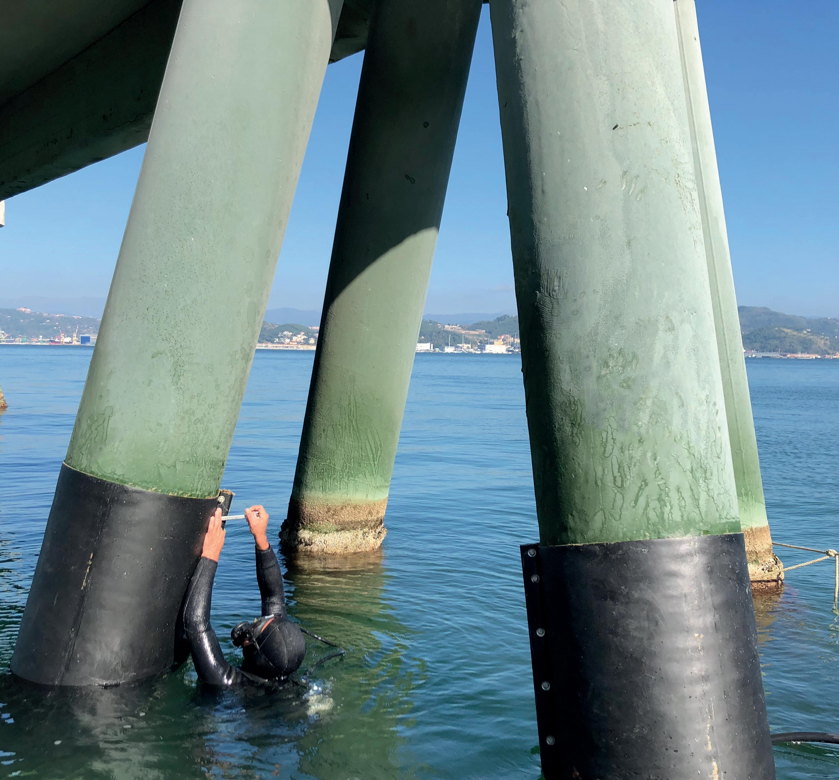

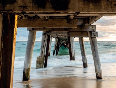
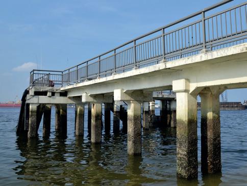
flow (preventing the pig from accidentally moving in the wrong direction).5 The receiver, on the other hand, has it upstream, preventing the pig from continuing down the line after it is received.5 While there are more vital components that make up a pigging valve, these pieces provide the essential understanding of how the design works.
The main components consist of:
) The trunnion-mounted ball valve.
) An opening on either the side or top for pig extraction/ introduction.
) A catcher/stopper plate located within the valve’s body.5
One notable difference between trap and pig valve designs is that certain elements, such as bypass lines, are not always essential for pig valves to operate as they are for traps.3,5 Many operations do install a bypass line to preserve flow during pig loading/unloading. Some operators also add upstream and downstream isolation valves to provide true double block and bleed.6 While this article’s scope does not cover an in-depth
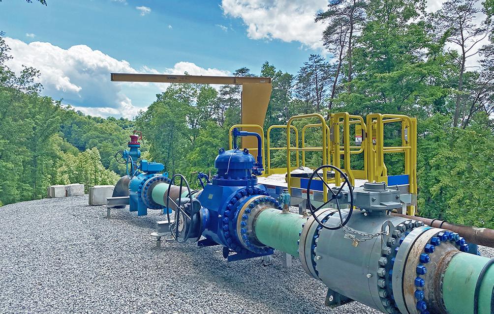
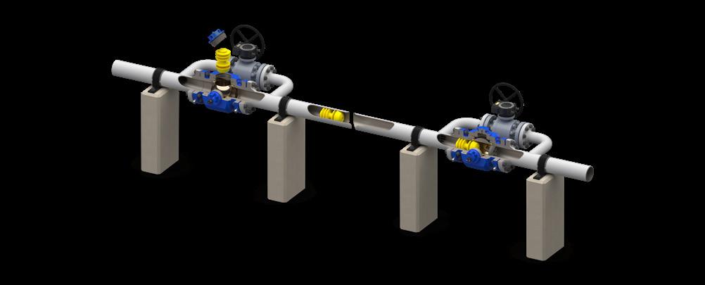
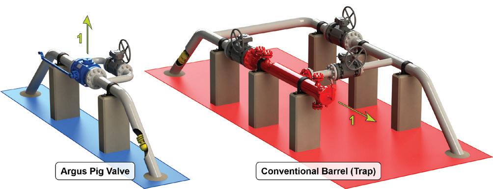
review of these different station setups, it is a noteworthy feature.
Pigging valves follow a similar operational logic to the barrel trap: create a safe cavity, load the pig, equalise, and then release the pipeline’s flow to launch it into the mainline.
How each phase is done, and the overall complexity of the operation, however, are inherently very different between the two stations because of their designs.
The following are general steps for the pigging valve launch sequence. Like the trap, these steps may vary depending on operator codes, design layouts, and other factors.
) Preserve flow (if a bypass is installed): the first step is to note whether the station has a bypass line in its configuration, or not. When the station configuration includes one, the first step is to open the bypass to preserve flow during pig loading.5
) Isolate the cavity and make it safe: once the bypass is open (assuming one is present), the pig cavity is isolated from the mainline by rotating the valve to the manufacturer’s defined ‘closed’ position. The valve is then depressurised and put to a safe condition using its vent and drain ports.5
) Load and secure: once safe, the access point is opened, any restrictor/restraining features are removed, the pig is inserted, and the restrictor is replaced. The access point is then closed and secured.5
) Equalise and launch: cavity pressure is equalised to the line pressure using the valve’s equalisation feature (often a level). The valve is then opened, rotating it to its original position. The flow from the mainline will then push the pig into the pipeline, like a trap launch.5
Once the pig is in the line, the operator can close the bypass and return the valve to its normal configuration
Inverting the order, we have the receiving processes for the pigging valve.
) Capture: the pig is first caught within the valve using its stopper plate. The stopper plate prevents the pig from moving past the ball and down the line.5
) Isolate and make safe: once the pig is captured, the valve is rotated to its ‘closed’ position, isolating the cavity. Vent/drain ports are then used to bring the cavity to a safe pressure.5
) Remove and restore: once safe, the access point is opened, the restrictor is removed if applicable, and then the pig. The restricted is then placed back into the valve, and the entry point is closed. Once closed, the cavity is equalised back to line pressure, opened, and the valve is returned to normal operation.5
As we have seen, although barrel traps and pigging valves serve a similar purpose, their architectures differ significantly. These
We are running out of space...
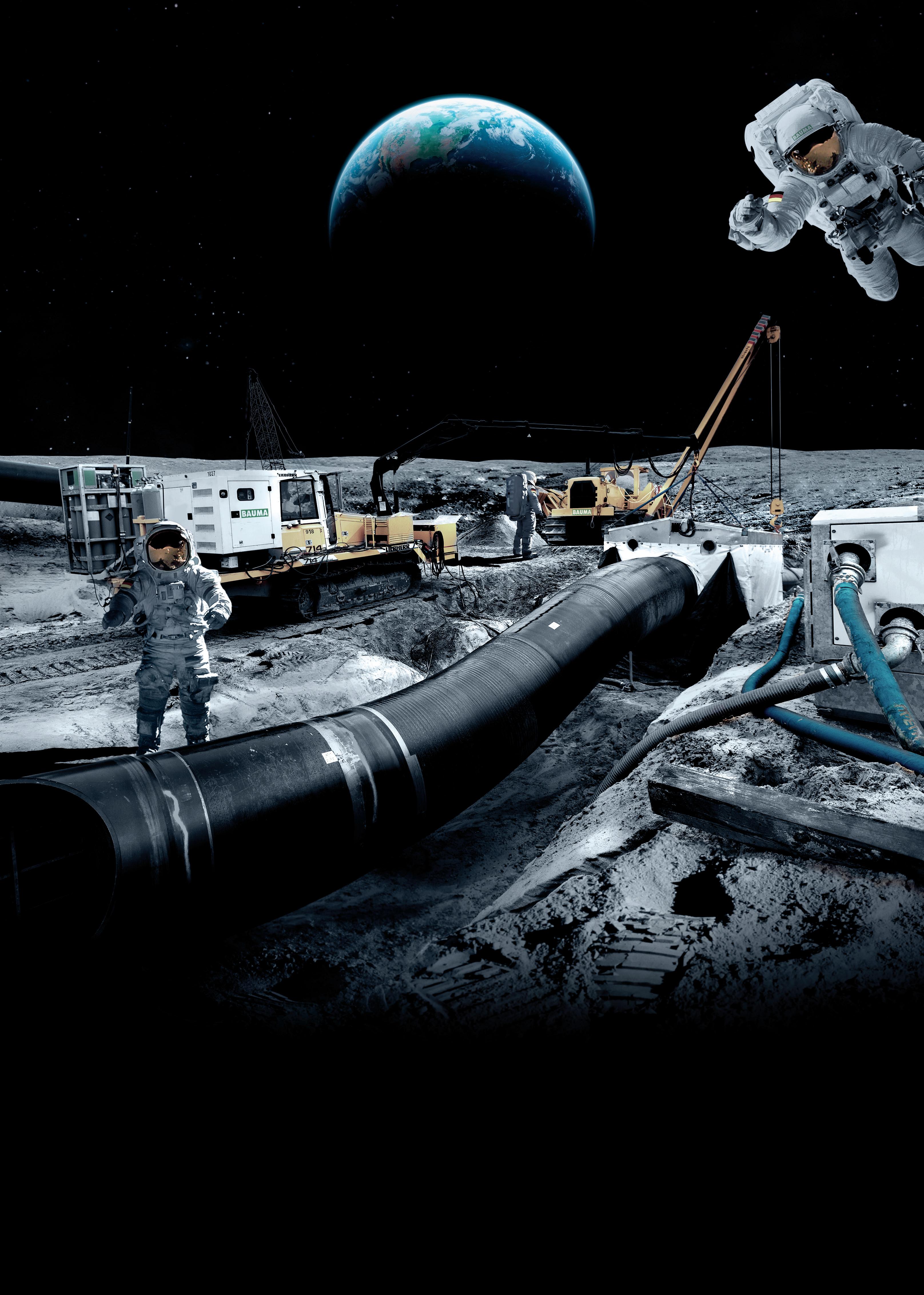
Our inventory in sales & rental in pipeline equipment is out of this world. We have a huge amount of machines from all the big brands that are ready for worldwide delivery, or even further if you want...
You can build on BAUMA!
differences create inherent differences in how operators use them, as we have seen. With those differences in mind, we will now examine how they shape each style’s advantages and disadvantages, and, together, how these factors influence the operating conditions under which each is best suited.
Pig tool compatibility
The first notable difference is the pig tool compatibility of each style. Obviously, this is important to operators, as they may need to send a range of ILI or maintenance pigs through a specific line. Those tools can vary greatly in design and geometry, and they need a trap that can accommodate them. In this aspect, barrel traps clearly have an advantage. The large chamber that barrel traps use to house the pigs is specifically sized to accommodate the longest tools the operator expects to run.7 Accordingly, the volume can be designed with relatively few practical limits on what pigs it can hold, beyond footprint and cost constraints. Pigging valves, on the other hand, are built with a much smaller internal cavity. The small cavity limits the variability in the pig geometry it can accommodate. Accordingly, this generally limits pig valves to accommodate maintenance pigs and single-module ILI tools.8
Footprint and installation flexibility
Ironically, the design aspect that enhances tool compatibility also limits the station’s retrofitting versatility. As we have seen, the conventional launcher/receiver station typically includes a major barrel, minor barrel, reducer, closures, and connected lines, valves, and nozzles.2 The complex layout and many components demand significant space to implement.2 As a result, this can make them very challenging for operators, especially when they are up against footprint constraints in areas such as offshore, flow lines, facility piping, or some gathering lines. Pigging valves, however, are compact and can often be integrated anywhere an operator can reasonably install a shutoff valve.9, 10 This makes pigging valves attractive when the operating conditions have space limitations.
The cavity/barrel size also significantly influences the GHG emissions each produces. During loading/unloading, the chambers housing the pigs must be depressurised through venting. Venting releases greenhouse and other toxic gases into the atmosphere, and the size of the chamber determines how much gas must be vented for safe depressurisation. The volume of venting required by the pig valve, therefore, is significantly smaller than that of a conventional barrel trap due to the smaller cavity.10 The EPA supports this claim, reporting that using a pig valve instead of a conventional barrel trap can reduce the volume of gas vented during depressurisation by approximately 80 - 95%, specifically because the pig valve cavity is much smaller.10 Therefore, for operators focusing on emissions reduction, pigging valves provide a clear advantage over barrel traps.10
Somewhat related to the previous point is safety and risk. The volume captured inside each station’s vessel poses inherent
safety risks from the toxicity and flammability of what is vented, as well as the stored energy of the pressurised vessel. Larger volumes vented put operators at increased risk of exposure to flammable or toxic environments and to oxygendeficient environments, which can lead to fatal incidents.11 As for stored energy, the high-pressure volumes within traps, if not properly isolated and depressurised, can eject pigs or materials at high velocity.12 The National Energy Board has several well-documented cases of such incidents happening.11
Both barrel traps and pigging valves can be operated safely when safety procedures are properly followed. However, the barrel trap houses a significantly larger volume of gas, which increases the risks noted above.10 In addition, pigging valves are often designed for top-entry access.5 Topentry access puts operators in a safer position during loading and unloading, as the horizontal opening of a barrel trap can put workers in the line of fire in the event of an incident.4,9 Altogether, pigging valves reduce operator exposure during launching and retrieving operations, providing clear safety benefits to workers and operators.9
Both barrel traps and pigging valves serve the same essential purpose of sending and retrieving pigs from inline. Their designs and procedures, however, are very different, leading to inherent differences in where their strengths and weaknesses lie. Barrel traps often offer more versatility in what pig geometries they can accommodate, but trade this for larger space and higher venting requirements. Pigging valves, on the other hand, sacrifice some tool compatibility for a compact valve design that allows for more versatility in installation and lower venting volumes, providing both safety and emission benefits. Ultimately, the right choice of station depends on your tool needs, available space, and operational priorities.
1. CORDELL, J. and VANZANT, H., Pipeline Pigging Handbook, Houston; Louisianna: Clarion Technical Publishers, 2003.
2. Pipeline Engineering & Supply Co. Ltd, ‘Standard Pig Launcher/Receivers’, Richmond.
3. SUTTON, I., ‘Pig Launching and Retrieving’, Golf Professional Publishing, 2017.
4. Girard Industries, ‘Girard Industries’, 7 July 2020. [Online]. Available: https:// girardindustries.com/pdf/Launching_Retrieving_Procedures.pdf. [Accessed 9 February 2026].
5. Argus Machine Co. Ltd, ‘Pig Valve 6” - 12” Model D installation, operation, and maintenance’, Argus Machine CO. Ltd, Edmonton, 2023.
6. Argus Machine Co. Ltd, ‘Pig Valve - Typical Double Block and Bleed Installation with Bypass Line’, Argus Machine Co. Ltd, Edmonton, 2022.
7. Society of Petroleum Engineers (SPE), ‘Pipeline pigging’, 29 January 2025. [Online]. Available: https://onepetro.org/spe/general-information/1936/ Pipeline-pigging. [Accessed 9 February 2026].
8. Argus Machine Co. Ltd, ‘Compatible Pigs for Argus Pig Valves’, March 2025. [Online]. Available: https://www.argusinnovates.com/public/download/ files/216199. [Accessed 10 February 2026].
9. Argus Machine Co. Ltd, ‘Pigging Products Brochure’, Argus Machine Co. Ltd, Edmonton, 2024.
10. US Environmental Protection Agency (EPA), ‘Enforcement Alert: Natural Gas Gathering Operations in Violation of the Clean Air Act’, US Environmental Protection Agency, Washington, DC, 2019.
11. Energy Safe Canada, ‘Controlling Chemical Hazards: Pipeline Management Pigging (Guidance Sheet)’.
12. National Energy Board, ‘Pipeline Pigging Operations: Open to Injury’, National Energy Board, Calgary, 2007.
13. Alnitak3, ‘Pigging station’, Wikimedia Commons. Available: https://commons. wikimedia.org/wiki/File:Pigging_station.jpg (accessed 18 Feb 2026). License: CC BY-SA 4.0.
Joe Van Vynckt, CEO, Charps, addresses how pre-commissioning integrity is being redefined.
For more than half a century, pressure testing, also known as hydrotesting, has been a cornerstone of pipeline pre-commissioning. Before any new pipeline, or pipeline that transports hydrocarbons, can operate, it must prove that it can safely handle its intended operating pressure without leaks, structural compromise, or integrity concerns. Existing or ‘in-service’ pipelines are often required to be pressure tested under specific conditions to verify integrity, satisfy regulatory requirements, or re-establish maximum allowable operating pressure (MAOP).
It’s a simple concept on paper: fill, pressurise, hold, and verify. But in practice, it’s one of the most technically demanding, time-consuming, and risk-sensitive operations in the entire commissioning sequence.
Historically, the procedure has relied on manual observation, pressure charts, and subjective interpretation – methods that, while serviceable, have changed little since the 1970s. Yet the pipeline industry around it has transformed. Digital twins, real-time data feeds, and predictive analytics are now standard elsewhere in the life
cycle. It was only a matter of time before pressure testing caught up.
That transformation is now underway.
Pressure testing is more than a regulatory checkbox; it’s the final proof of construction integrity before a pipeline goes live. Conducted after fabrication, welding, and cleaning, the test simulates the pipeline’s operational conditions and verifies its ability to maintain pressure without leaks or material deformation.
Regulators such as the Pipeline and Hazardous Materials Safety Administration (PHMSA) and standards like API RP 1110 and ASME B31.4 mandate pressure tests as part of a commissioning programme. For operators, the test not only validates workmanship and design but also provides baseline data that informs future integrity assessments. In highconsequence areas, this process is critical to environmental protection and community safety.
The traditional workflow is well known; fill the pipeline, raise pressure gradually to the specified test value, hold it for a defined duration (often eight hours), then depressurise and dewater. Throughout the process, pressure and temperature are monitored, with data logged and interpreted to confirm whether any drop indicates a true leak or a natural thermal shift.
Yet this simplicity masks a complex challenge: the relationship between pressure and temperature is nonlinear. A 1˚ temperature change can mimic a pressure loss that appears to signal a leak. Engineers have spent decades trying to distinguish the two through manual corrections and experience. That guesswork has often led to unnecessary re-tests, project delays, and millions of wasted costs.
For decades, pressure testing technology has stagnated. Operators relied on analog gauges, periodic digital readings, and hand-written notes that were later entered into spreadsheets. Data density was low, interpretation was delayed, and conclusions were sometimes ambiguous. If a pressure drop was seen, teams might halt the test, suspect a leak, and re-pressurise, only to discover the issue was thermal contraction.
In this outdated paradigm, testing outcomes depended heavily on operator judgment. The margin for error wasn’t just scientific; it was human. In large, multi-segment projects, a single retest could mean several days of schedule slip, additional labour mobilisation, and costly water management activities. The environmental footprint and safety exposure from repeating fill-and-bleed cycles also grew with each uncertainty.
This was the environment that Charps set out to change.
For over 25 years, Charps has been a trusted name in pipeline construction, maintenance, and integrity management across North America. From coating rehabilitation to valve replacements, anomaly digs to system upgrades, the company has earned its reputation by executing with precision, transparency, and safety at scale. Our philosophy is simple: integrity management is a continuous lifecycle, not a one-time project.
The teams approach each pressure test as both a verification event and a learning opportunity. Every weld, every joint, every piece of documentation contributes to a larger integrity story. Our commitment to disciplined project management and rigorous QA/QC ensures compliance with 49 CFR Parts 192 and 195, while our emphasis on safety aligns with API RP 1173 and ISO 45001 frameworks.
Yet even the most experienced contractors knew that the testing process itself, including data collection, interpretation, and approval, was overdue for innovation. The opportunity came when Charps partnered with PipeSense to integrate advanced sensing and analytics into their field operations.
PipeSense was founded with a mission to eliminate the uncertainty that has long defined leak detection and hydrotesting. The company’s PipeTest service, featuring its HydroView dashboard, reimagines the pressure test from start to finish. Instead of sparse manual readings, PipeTest captures ultra-high-frequency data – pressure, temperature, and stabilisation trends – every second, all visualised in real time through a client dashboard.
Where a traditional hydrotest produces a few dozen data points, PipeTest generates hundreds of thousands. And with that granularity comes insight.
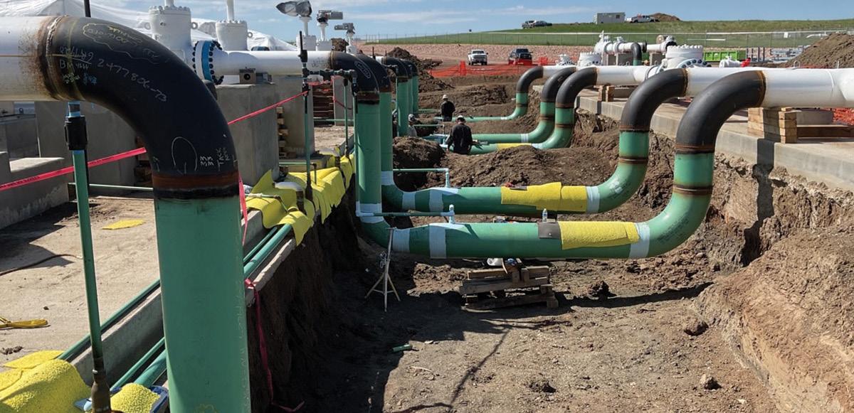
PipeTest integrates:
) Real-time temperature correction, using ground and fluid sensors to distinguish true pressure loss from thermal drift.
) AI-driven leak detection and localisation, pinpointing leak events often within ±30 yards in under two minutes.
) Interactive visualisation, allowing inspectors and engineers to monitor every aspect of the test live from any connected device.
The collaboration between Charps and PipeSense represents a convergence of field expertise and data science. Charps brings decades of practical experience executing pressure tests safely and efficiently, and PipeSense adds advanced analytics and automated intelligence that remove ambiguity from the process.
Together, the companies have created a system where every stage of pressure testing – planning, execution, verification, and reporting – is digitised, traceable, and instantaneous. Engineers no longer wait hours to interpret charts. Supervisors no longer debate whether a pressure decline is thermal or structural. The answer is right there, in the data. For operators, this partnership means:
) Integrated planning tests are developed and reviewed between all parties, ensuring safety, efficiency, and cost-effectiveness of execution by aligning resources, schedules, and controls.
) Faster turnaround times – tests can be approved or flagged in real time, often saving full days on the schedule.
) Reduced resource use – fewer retests mean less water handling, less energy consumption, and smaller environmental impact.
) Improved compliance – digital records are auditable and align with PHMSA documentation requirements.
) Increased confidence – clear, temperature-corrected data removes the guesswork from pass/ fail decisions.
This approach transforms what was once a reactive process into a predictive one. It brings the same level of intelligence that operators expect from leak detection or pig tracking into the pre-commissioning phase, closing the loop on lifecycle integrity.
How pressure testing actually works – and how it’s changing
At its core, a pressure test involves four key phases:
The pipeline is cleaned, filled, and instrumented with pressure and temperature sensors. Valves are secured, and test limits are set.
Pressurisation and hold
Pressure is raised gradually to the target test level and held for a defined period, during which stability is monitored.




Pressure and temperature data are collected continuously to assess stability and identify anomalies.
Once the test passes, pressure is released, and data are compiled for final reporting.
Traditionally, the monitoring and verification phase relied on intermittent manual readings. Now, with systems like PipeTest, data is captured continuously, analysed in real time, and correlated automatically to ambient and fluid temperature. This innovation virtually eliminates false indications and allows operators to see the precise moment of stabilisation.
Instead of waiting until after depressurisation to determine success, test engineers can make data-driven decisions during the test itself. This real-time visibility not only accelerates commissioning but also strengthens safety by enabling immediate response if a true leak event occurs.
The benefits of modernised pressure testing extend well beyond engineering convenience. The implications touch every aspect of project delivery and asset management:
) Schedule efficiency: eliminating retests can shorten commissioning timelines by days or weeks – an advantage that compounds across multi-segment projects.
) Cost reduction: accurate, temperature-corrected analysis prevents unnecessary re-pressurisation and resource waste.
) Regulatory readiness: the HydroView dashboard’s digital audit trail simplifies compliance documentation and third-party review.
) Environmental stewardship: less water usage, fewer emissions from retesting, and minimised site disturbance align with corporate ESG goals.
) Stakeholder confidence: operators, regulators, and contractors share one transparent dataset, ensuring mutual understanding and accountability.
In short, what was once an opaque, uncertain process is now a transparent, data-validated demonstration of pipeline readiness.
Charps and PipeSense have collaborated on multiple live projects across North America, applying PipeTest technology alongside Charps’ field expertise. Results have included:
) Retests were reduced by more than 70%, thanks to early identification of micro-leaks and temperature-related anomalies.
) Real-time approvals, with test outcomes verified immediately upon stabilisation.
) Fewer false positives, leading to measurable savings in time, water, and labour.
A data ecosystem for the entire pipeline lifecycle
The modernisation of pressure testing is only one piece of a broader transformation. Additional technologies for continuous leak detection, blockage identification, and pig tracking extend the same real-time visibility into every stage of pipeline operation.
For Charps, this integration enhances our core mission of maintaining safe, reliable, and compliant pipelines throughout their service life. What begins as a pressure test evolves into a continuous data stream that supports future inspections, maintenance, and regulatory reporting.
This ecosystem approach – combining field execution with edge computing and AI analytics – creates a future where pipeline integrity is not just validated periodically but monitored continuously.
The human element: expertise still matters
While technology has transformed pressure testing, success still depends on skilled professionals who understand the nuance of pipeline behaviour. Certified crews, with decades of field experience, remain essential in ensuring tests are performed safely and in compliance with regulations. PipeSense’s systems don’t replace that expertise; they amplify it.
By equipping technicians with real-time insight, they can make better, faster, and safer decisions in the field. It’s a synergy of human judgment and digital precision –one that keeps people and assets protected.
Looking ahead: the future of precommissioning
As the energy sector accelerates toward lower-carbon operations, emerging fuels like hydrogen and CO2 demand even more stringent verification protocols. Pressure testing will only grow in importance and complexity. Modernised, data-driven systems are already proving essential in these new applications, providing the accuracy and transparency regulators and communities now expect.
For Charps and PipeSense, the mission is clear: bring clarity where uncertainty once ruled, and efficiency where delays were inevitable. Together, they prove that pressure testing doesn’t have to be a slow, manual ritual. It can be a precise, intelligent process that accelerates safe startups and ensures long-term integrity.
Pressure testing remains the unsung hero of pipeline commissioning – a critical safeguard before the first molecule of product ever moves. But like so many legacy practices in the energy sector, it was overdue for reinvention.
By combining field excellence with advanced analytics, pressure testing has entered the digital age. The result is faster startup, better data, lower costs, and –most importantly – greater safety and confidence. In an industry built on precision, the message is simple: pressure testing has finally caught up with the 21st century.
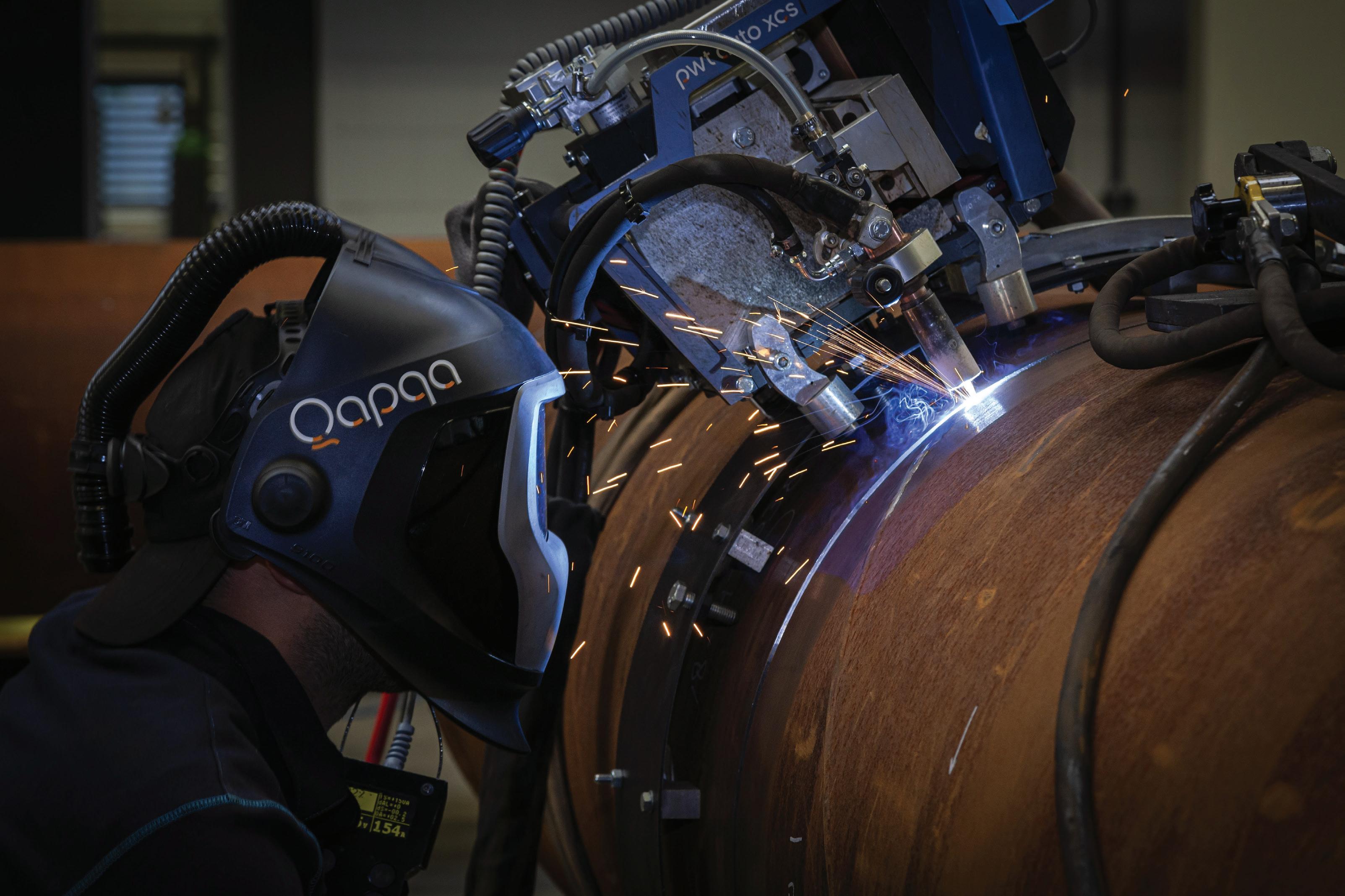
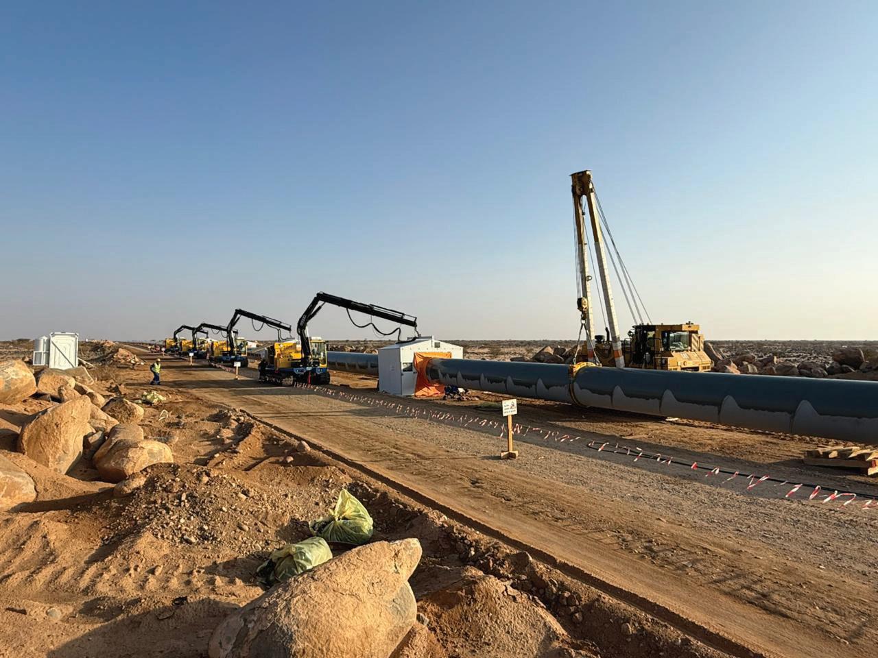
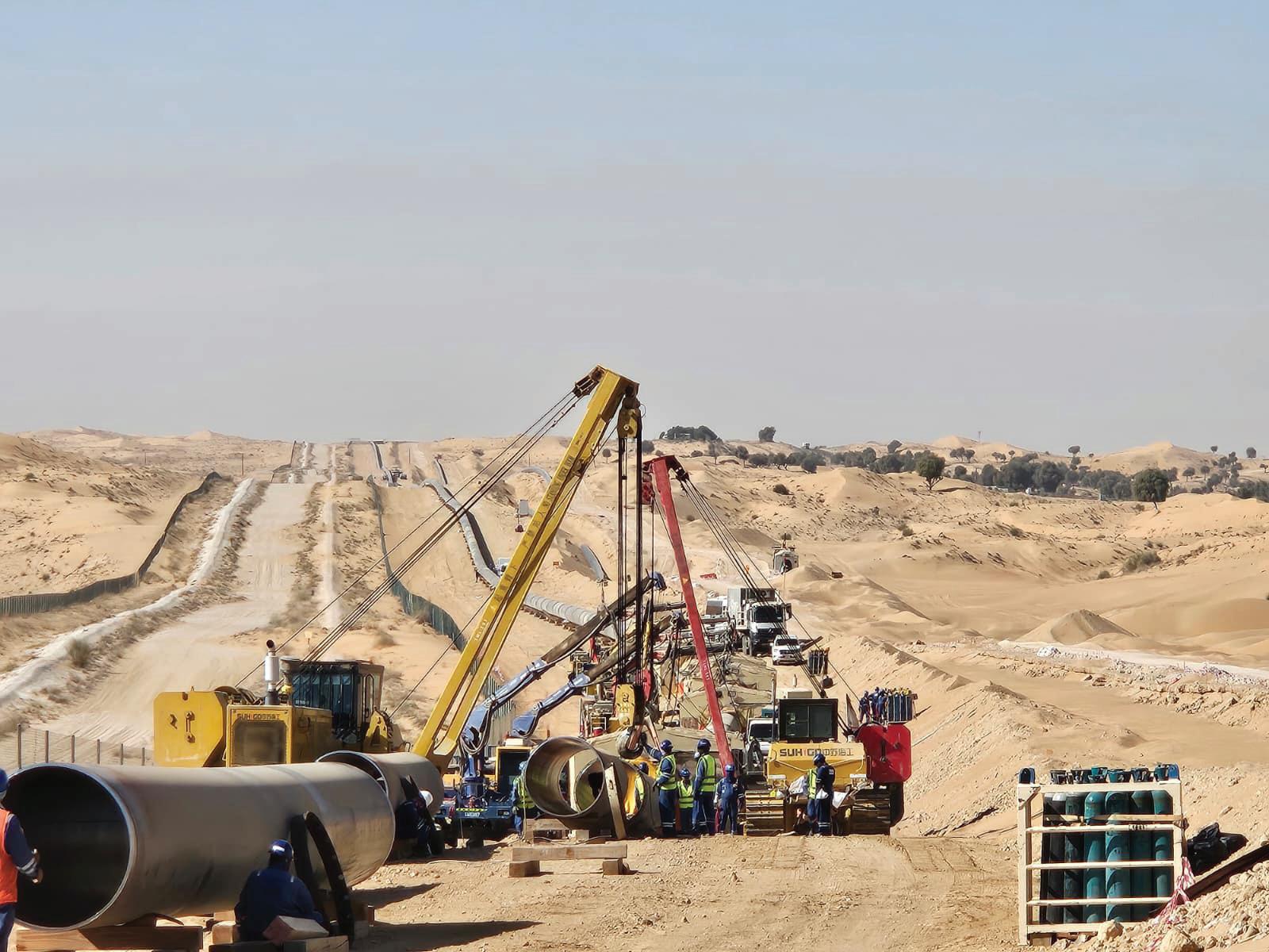
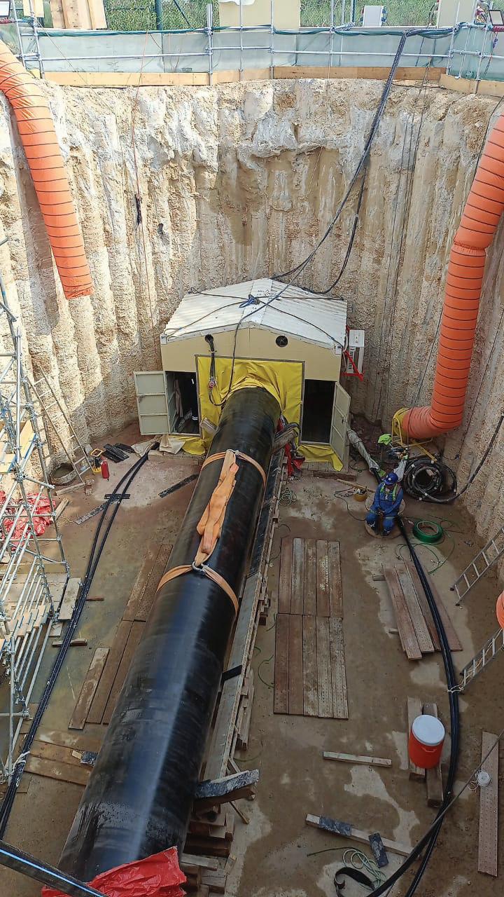
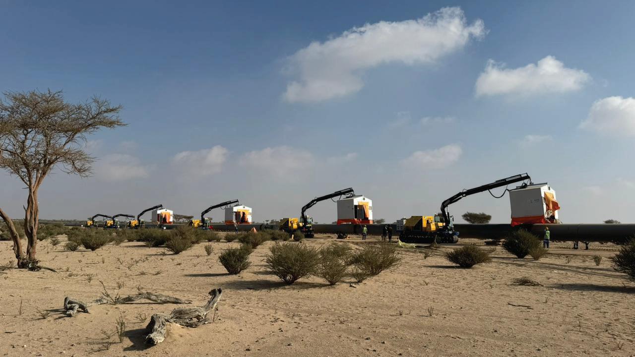
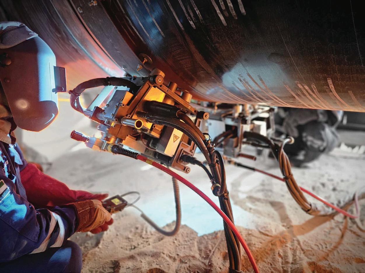
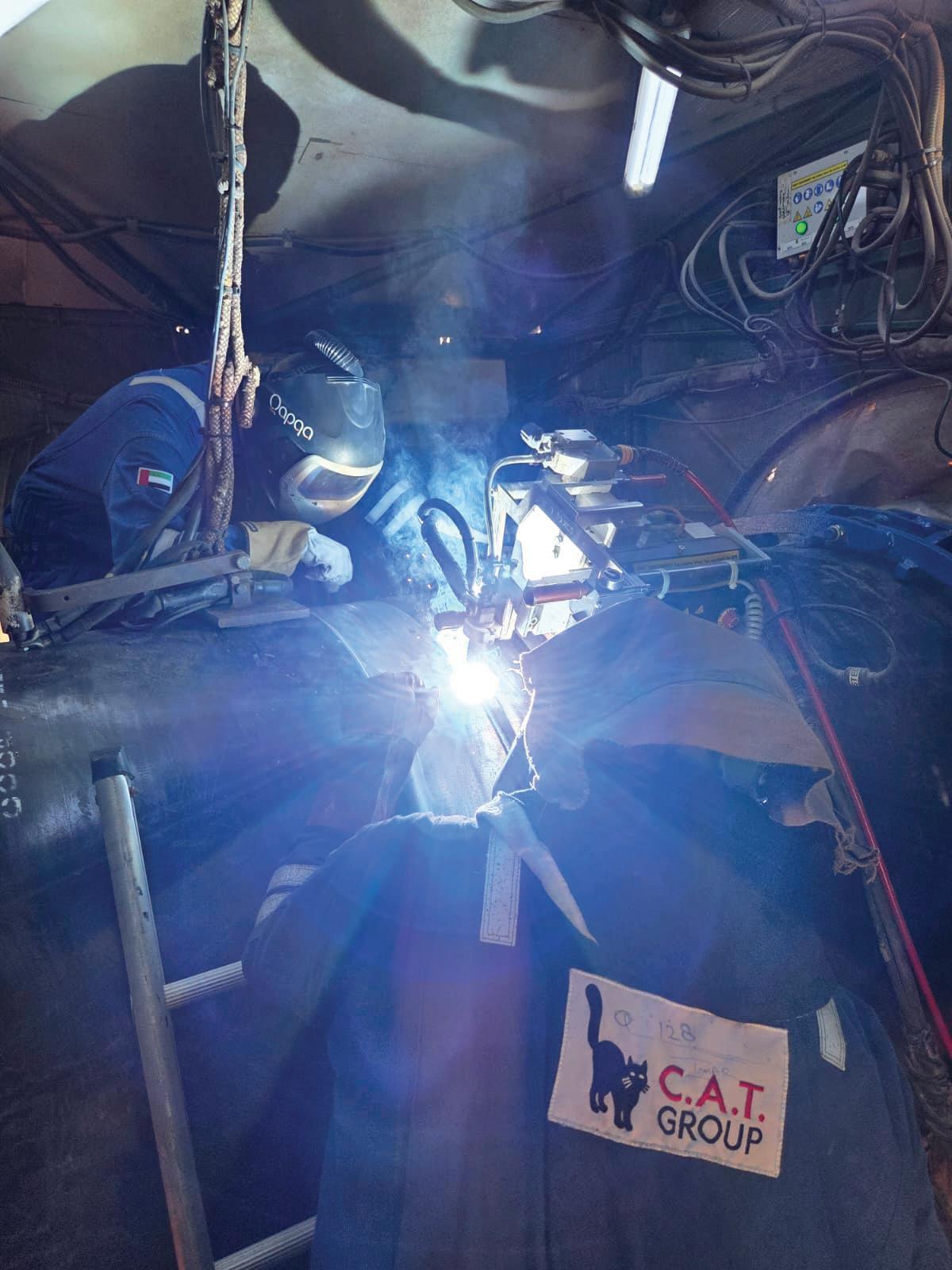
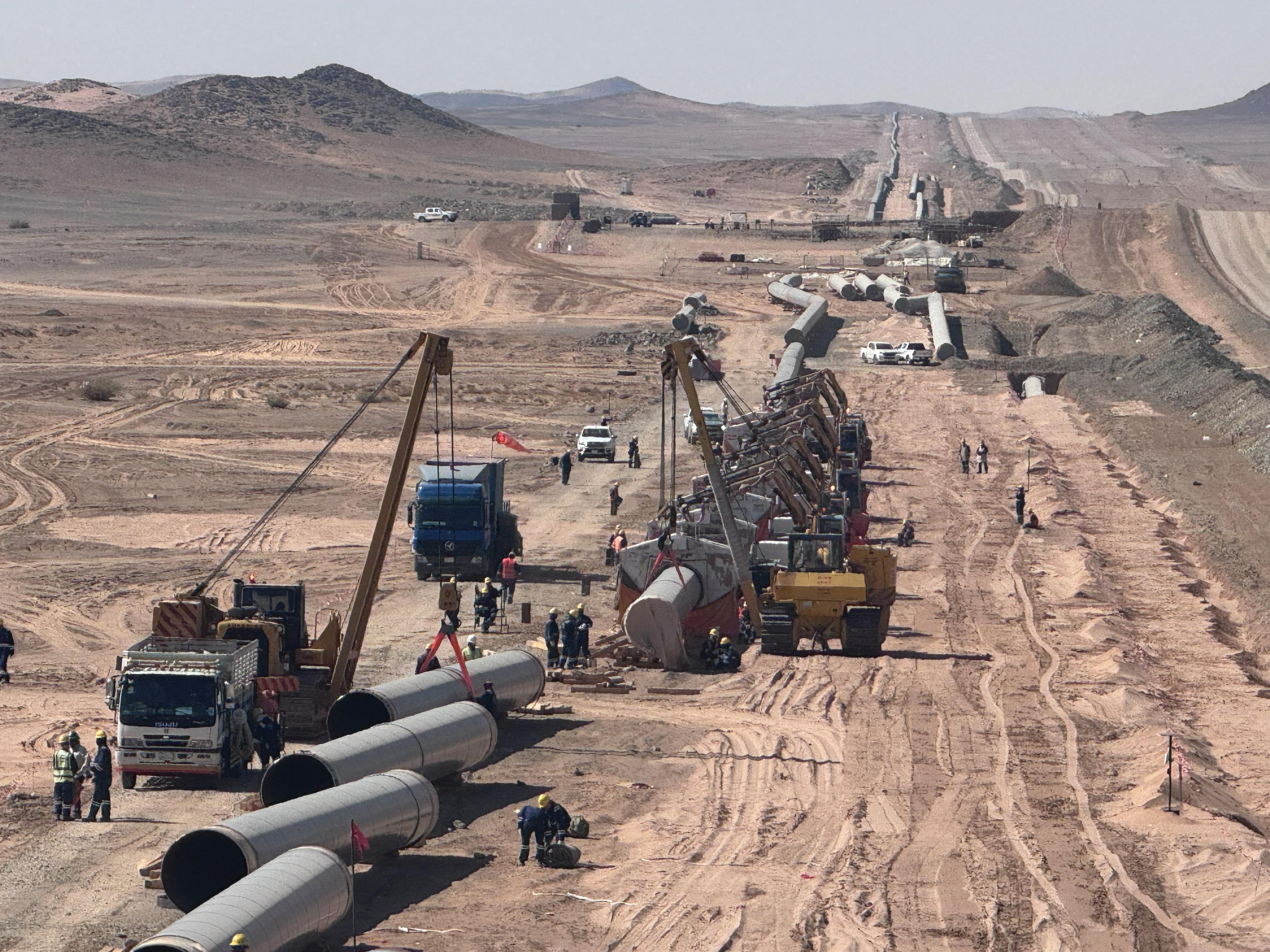
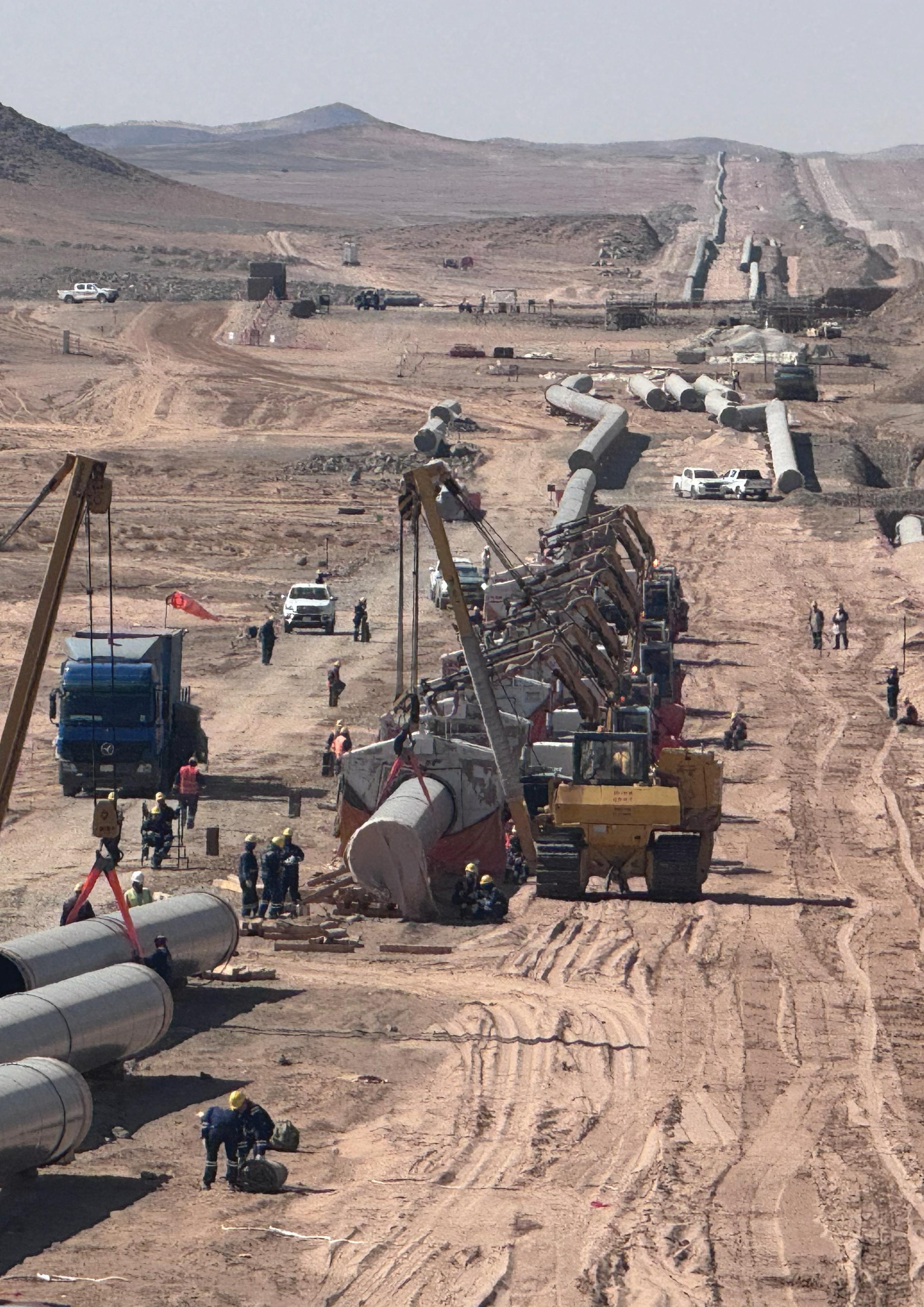

Matthew Guest and Ian Littlepage, Team, Inc., explore how to redefine isolation with fewer steps, lower risk, and greater reliability for pipeline operators.
Pipeline operators live in a world defined by paradox. They are asked to extend the life of ageing infrastructure while simultaneously adopting innovations to prepare for tomorrow’s energy landscape. They must protect people and the environment while keeping throughput high and downtime minimal. And at the centre of this balancing act lies one of the most deceptively simple yet operationally vital tasks: isolation.
For decades, double block and bleed (DBB) has been a necessary but complex process. Operators have been conditioned to expect multiple hot taps, reinforcement sleeves, and precise spacing requirements, all of which add cost, time, and risk. The work got done, but not without friction.
What if DBB didn’t have to be complicated? What if the safest way forward was also the simplest?
Enter Team’s SmartStop® system, a reimagined approach to line intervention that has the potential to shift the way our industry thinks about pipeline integrity.
Why isolation still keeps executives awake at night
Let’s be candid. Isolation is a headache.
) For executives, it represents cost, downtime, and liability exposure.
) For engineers, it requires juggling technical standards, reinforcement requirements, and safety protocols.
) For field crews, it means exposure to risk while verifying that seals hold as planned.
Traditional DBB asks a lot from everyone involved. It demands precision and patience in environments where both are in short supply. It is no surprise that many executives view
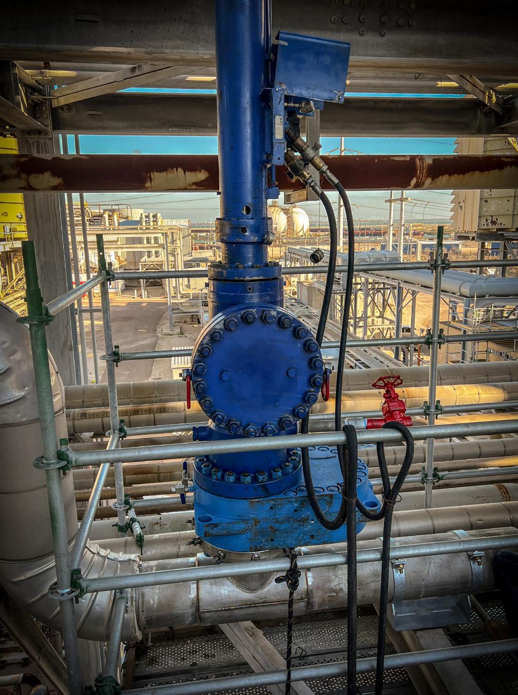
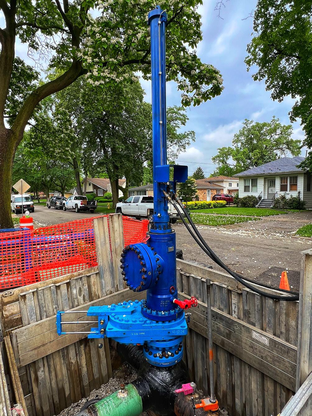
isolation as one of the most unpredictable line items in their maintenance budgets.
And yet, without it, no tie-in, retrofit, or repair can move forward. That makes DBB one of the most critical and one of the most ripe for disruption processes in the entire pipeline ecosystem.
Team’s SmartStop is not just a tool; it is a philosophy. It challenges the industry’s assumption that ‘more fittings’ and ‘more steps’ equal ‘more safety’. Instead, it achieves double block and bleed isolation through a single standard fitting which dramatically reduces the complexity operators have long accepted as the cost of doing business.
Key features include:
) One fitting, two barriers: a single fitting deploys primary and secondary seals, eliminating the need for multiple welds and hot taps.
) Integrated bleed port: operators can monitor and vent the space between seals in real time, proving zero energy without secondary interventions.
) Under-flow capability: thanks to a rigid rail system, SmartStop can be deployed even under significant flow
) Self-energised seals: seals engage automatically, not through external hydraulics or pressure differentials. Fewer moving parts mean fewer potential failures.
) Robust ratings: fully rated to ANSI 900# and tested up to 2220 psig, with NACE MR0175 compliance, SmartStop is built to handle the toughest conditions.
It strips complexity away. Reliability is achieved by reducing the degrees of freedom: fewer parts, fewer steps, fewer uncertainties.
For executives weighing the future of their integrity programmes, SmartStop offers more than a technical upgrade. It is a strategic asset.
) Reduced downtime means higher throughput and lower costs.
) Built-in monitoring reduces liability and reassures regulators.
) Simplified process reduces labour demands on already stretched crews.
) Safer field execution protects both people and brand reputation.
In other words, it is not just solving a technical problem. It is solving a business problem.
Operators who have deployed SmartStop often remark on the psychological shift it creates in the field.
Traditionally, verifying seal integrity was one of the most stressful moments of an intervention. Crews would stand exposed, conducting extra taps just to prove zero energy. Each tap meant more cutting, more welding, more risk.
With this system, that stress disappears. The integrated bleed port and zero-energy monitoring provide immediate,
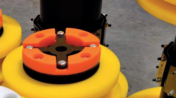
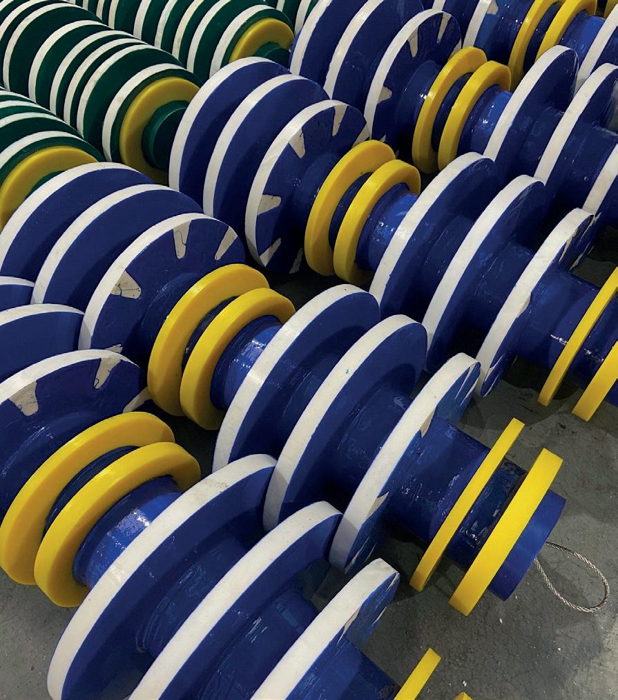
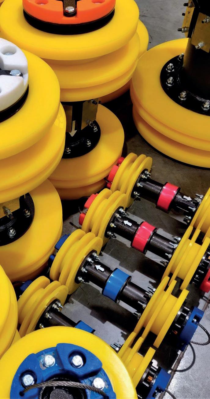
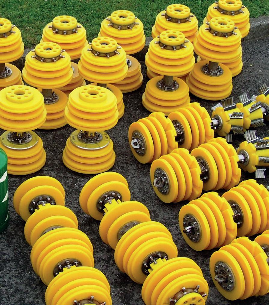
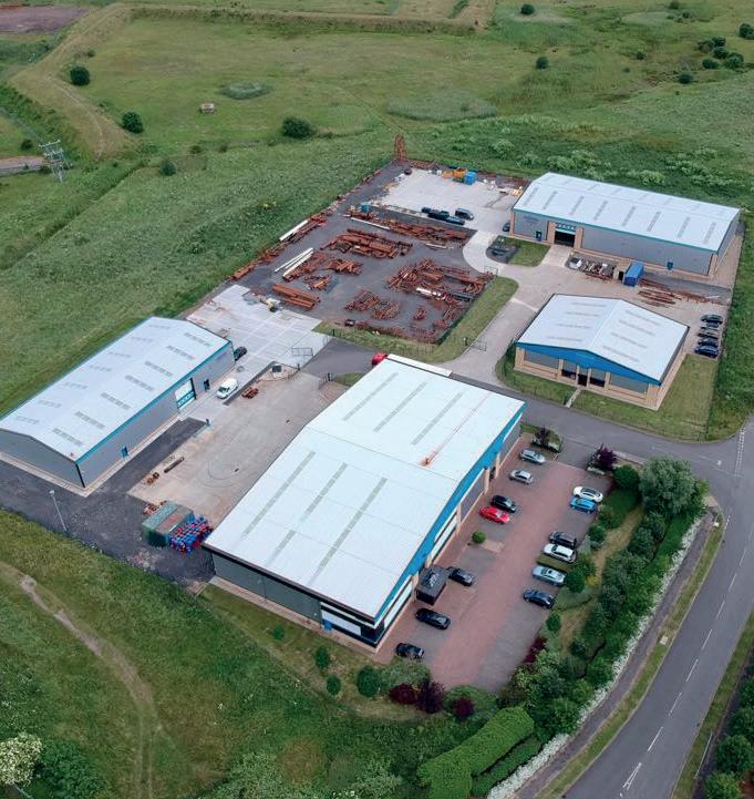
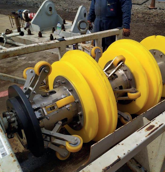
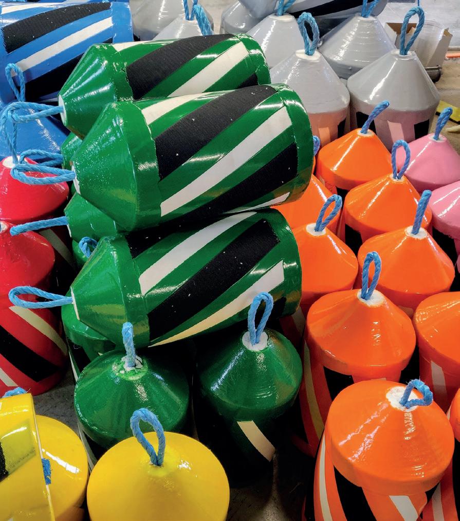
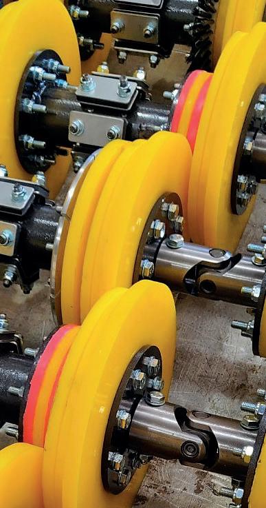

continuous confirmation. Crews can focus on the job at hand rather than the anxiety of whether the isolation will hold.
Executives, too, notice the difference. Projects run smoother, schedules hold tighter, and risk registers shrink. It has the potential to change the cultural relationship between operators and isolation, from dread to confidence.
The bigger picture: integrity in an era of scrutiny
Our industry is operating under a microscope. Regulators are tightening requirements. Investors are asking tougher questions
about ESG. Communities are more vocal about safety and environmental risk.
Against this backdrop, innovations like SmartStop do more than improve operations; they strengthen trust. An operator who can demonstrate that they are adopting forward-thinking, safety-first solutions is not just reducing downtime. They are showing regulators, investors, and the public that they are serious about doing the right thing.
That kind of credibility is priceless in today’s operating environment.
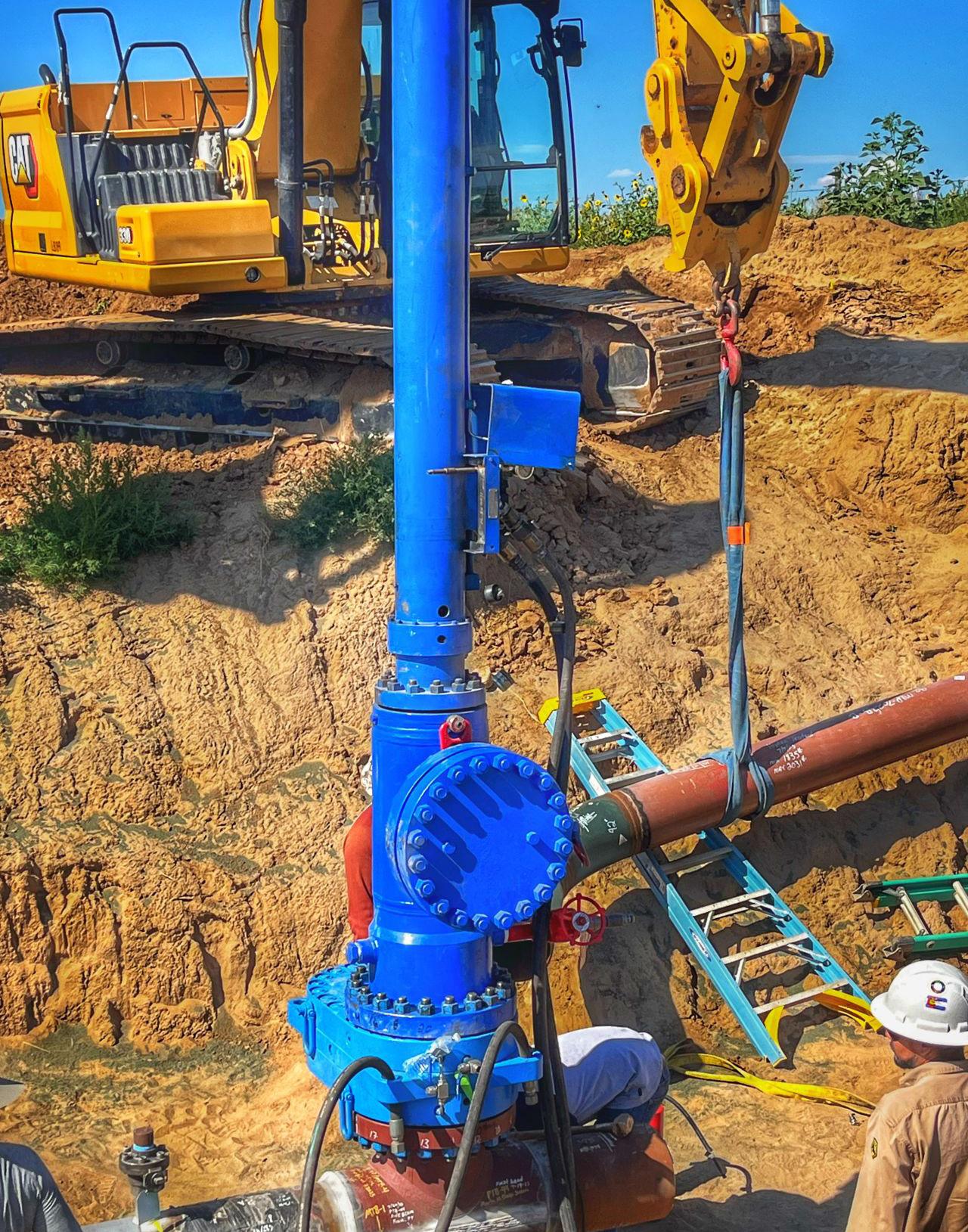
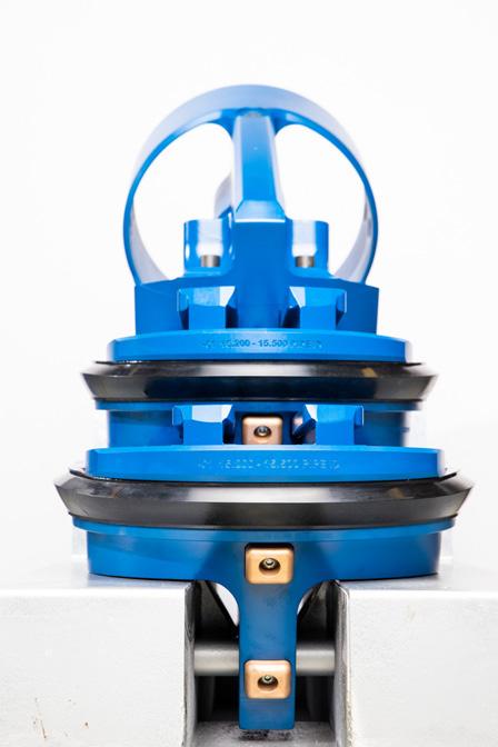
bridge to the future
Pipeline infrastructure is aging, but demand is not slowing down. That puts tremendous pressure on maintenance strategies. Operators need solutions that can help them safely extend the life of their assets while also preparing for whatever the future of energy holds: hydrogen, carbon capture, or fuels yet to come.
SmartStop is built for that future. Its adaptability across a range of diameters (currently 4 - 24 in., with larger sizes in production) and applications makes it a long-term investment in resilience. Its ability to re-enter existing fittings ensures that today’s work lays the foundation for tomorrow’s needs.
This is not just about solving today’s isolation problem, it is about future-proofing your pipeline programme.
Thought leadership in pipeline integrity is no longer just about keeping up with regulations. It is about staying ahead of them. It is about running leaner, safer operations that protect people, the planet, and the bottom line.
SmartStop represents forward-thinking innovation. It is a solution born from decades of field experience, engineered with relentless focus on reliability, and designed to meet the realities of 21st century operations.
For executives making decisions about where to invest in integrity management, the message is clear: the future of isolation is not complicated. It is smart.
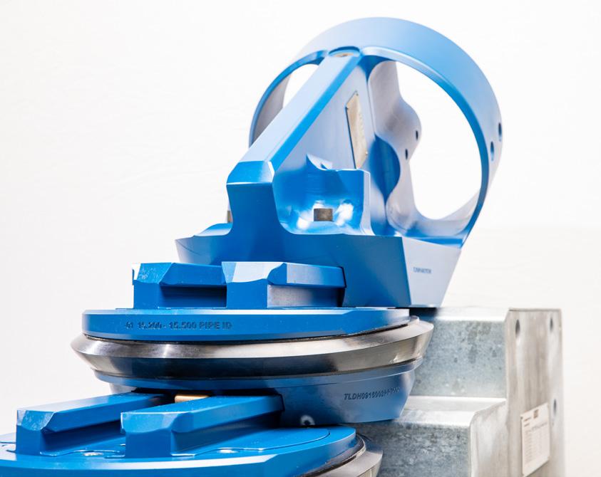
There is a saying in engineering: simplicity is the ultimate sophistication.
For too long, the industry has tolerated unnecessary complexity in one of its most vital processes. Team’s SmartStop shows us another path, one where safety, reliability, and efficiency are designed in, not bolted on.
In doing so, it does not just change how we isolate pipelines. It changes how we think about pipeline integrity altogether.
The future of isolation has arrived. And it is simpler, safer, and smarter than we ever thought possible.
Fernando Arce-Larreta, Iron Gate Supply President and BridgeFlow
Valve Partner, considers the inherent risk posed by traditional single blind flange and DB&B systems, and the measures that operators can undertake to mitigate the dangers while introducing more contemporary integrated isolation technologies that eliminate these risks.
Within worldwide pipeline networks single blind flanged and double block and bleed (DB&B) isolation connections have traditionally been accepted as the established practice for isolation tie-in and maintenance opportunities. While these designs have historically met industry needs, they no longer align with today’s standards for safety, emissions, reliability, and total cost of ownership. Operators are under growing scrutiny with methane emissions, safety, and working conditions. This is driving the need to re-think traditional isolation design approaches.
Recent events within the oil and gas industry have highlighted that flange handling, gasket failures, and trapped pressure have been and will continue to be contributing factors to leaks and serious safety incidents.
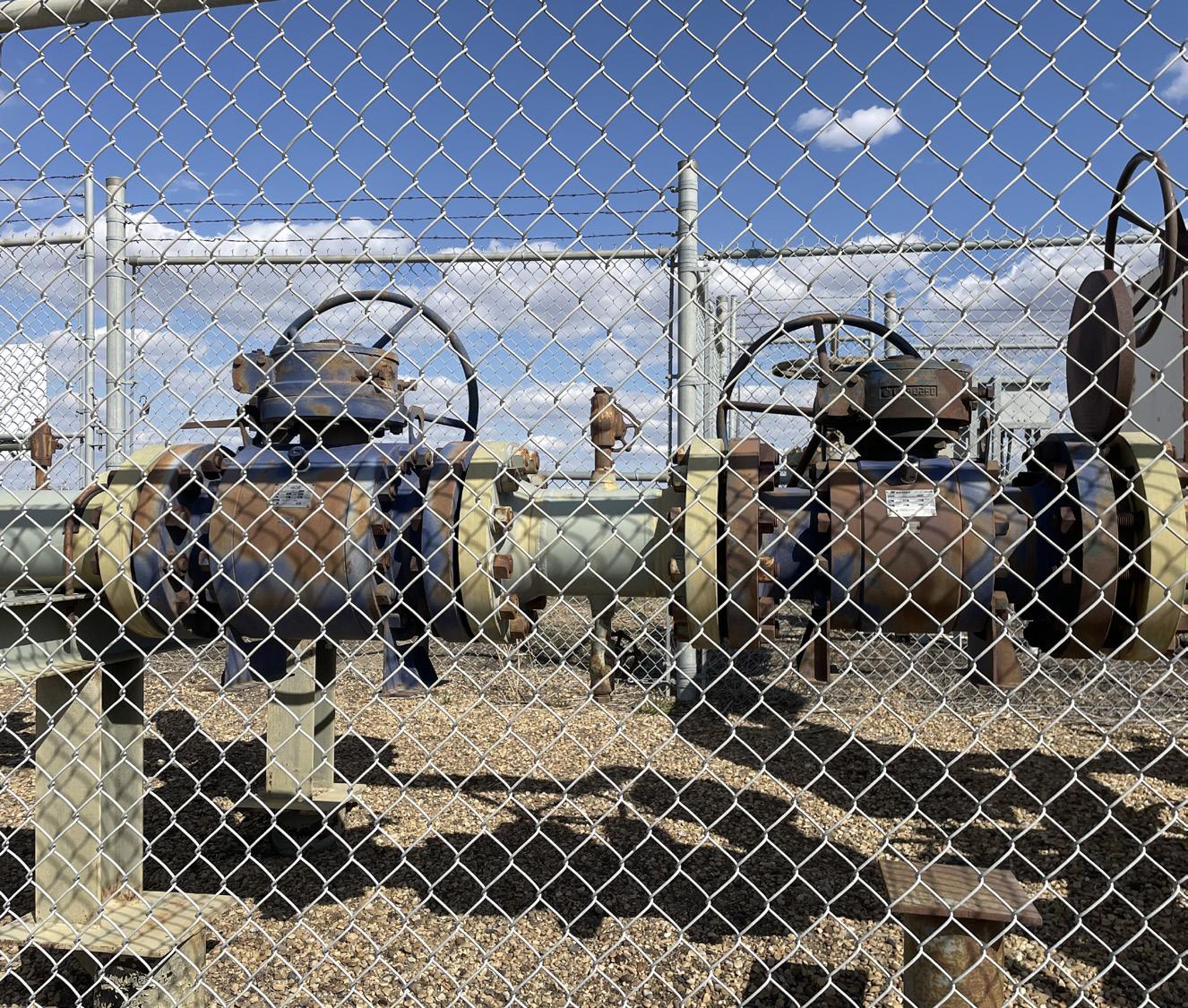
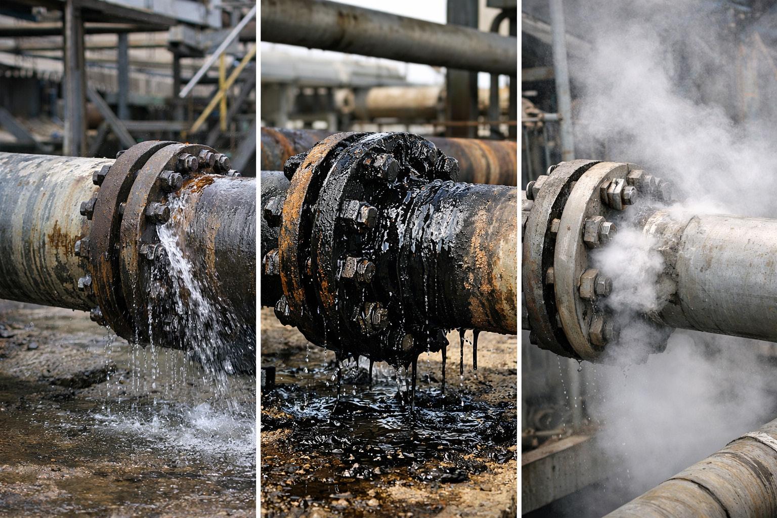
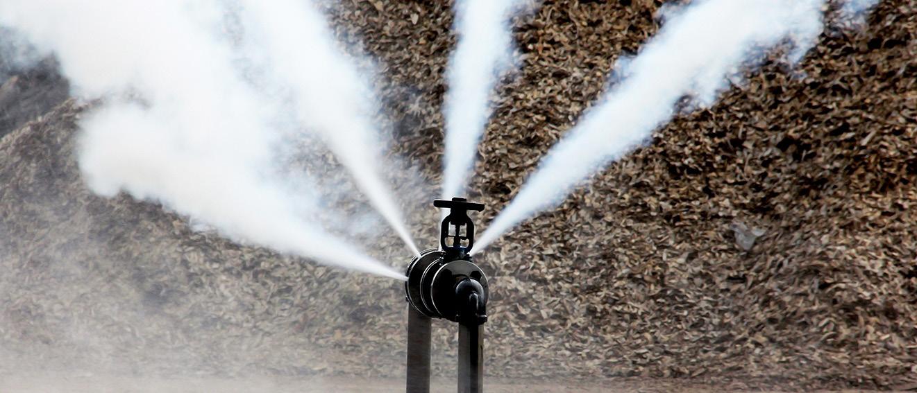
This article intends to discuss the inherent risk posed by traditional single blind flange and DB&B systems. With a focus on the measures that operators can undertake to mitigate these dangers while introducing more contemporary isolation technologies that eliminate these risks. In conjunction, this effort aligns with the industry’s broader shift towards simplification, decarbonisation, and safer pipeline infrastructure.
The hidden risk profile of legacy isolation configurations
Single blind flange and double block and bleed assemblies add numerous mechanical interfaces into a pipeline pressure boundary. A single blind flange gasket bleed valve and a threaded connection can create a leak path. A number of these connections have been incorporated into constrained space locations like valve vaults, compressor stations, and offshore towers.
Recent industry expert insights on pipeline integrity and safety sources have highlighted that flanges are still a very common source of fugitive emissions and unplanned releases. Incorrect bolt torque, gasket damage, and pressure transients remain factors that contribute towards leaks. The inclusion of bleed valves on pipelines can also lead to more modes of failure. This is primarily due to valve seat leakage, stem packing, and obstructed bleed paths.
A DB&B coupling is commonly considered to offer safety and redundancy. In fact, it offers false confidence. Experience across many facilities has shown that it is possible for both isolation valves do not seal properly due to debris, seal misalignment, or pressure differential effects. Should valve isolation be checked with the bleed valve, trapped pressure may not be detected leading to potentially serious consequences for the maintenance crew.
Industry incident reports have included instances associated with trapped pressure within a closed DB&B assembly that caused uncontrolled releases when loosening flange connections. These incidents put operators directly at risk from high-pressure hydrocarbons that can result in serious injuries, fatalities, and environmental releases.
Methane emissions have emerged as an area of prime concern for regulators, investors, and operators. Recent environmental agency
Maintain continuous, reliable cathodic protection with Dairyland decouplers.
Dairyland decouplers optimize cathodic protection systems by isolating the flow of DC current to a grounding system or other equipment. Simultaneously, they provide a path to ground for AC faults and lightning, keeping assets and personnel safe from hazardous events. Dairyland decouplers deliver rugged and reliable protection, without compromising CP performance.
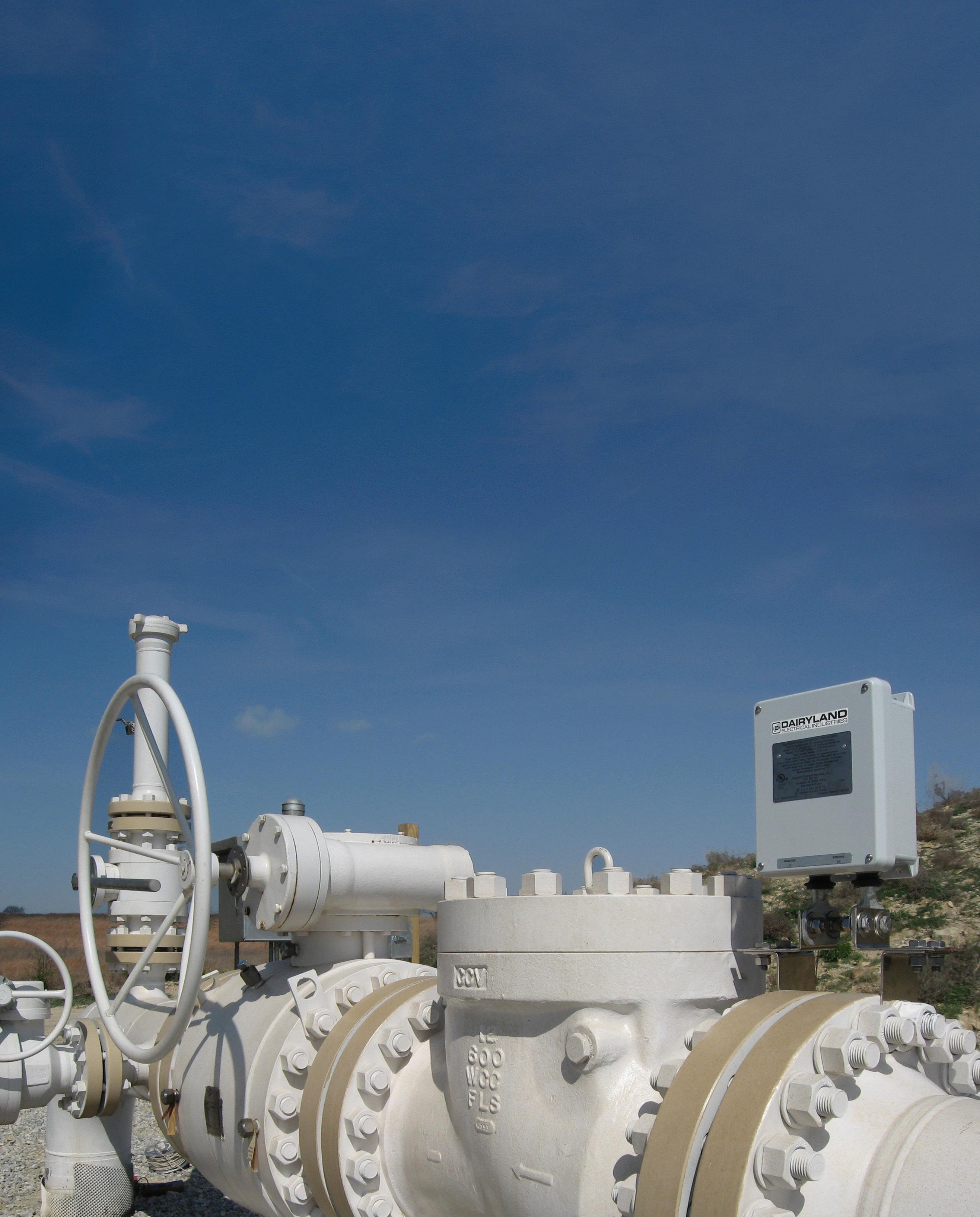
Explore our product line and learn more at Dairyland.com/Decouplers
reports and third-party studies identify flanges and valves as major contributors to fugitive emissions. A cumulative effect of low leakage rates among the thousands of flange connections contributes substantially to emissions.
Thus, single blind flanged and DB&B designs are more likely to raise the number of emission sources within a given system, due to the increased number of valves. Each gasket seal and bleed valve represents an unbroken source of leakage that needs to be continuously monitored. This is critical to operations given the changes taking place within morerestrictive measurement and reporting obligations. Single blind
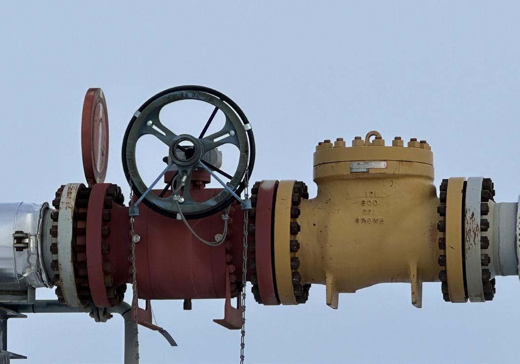
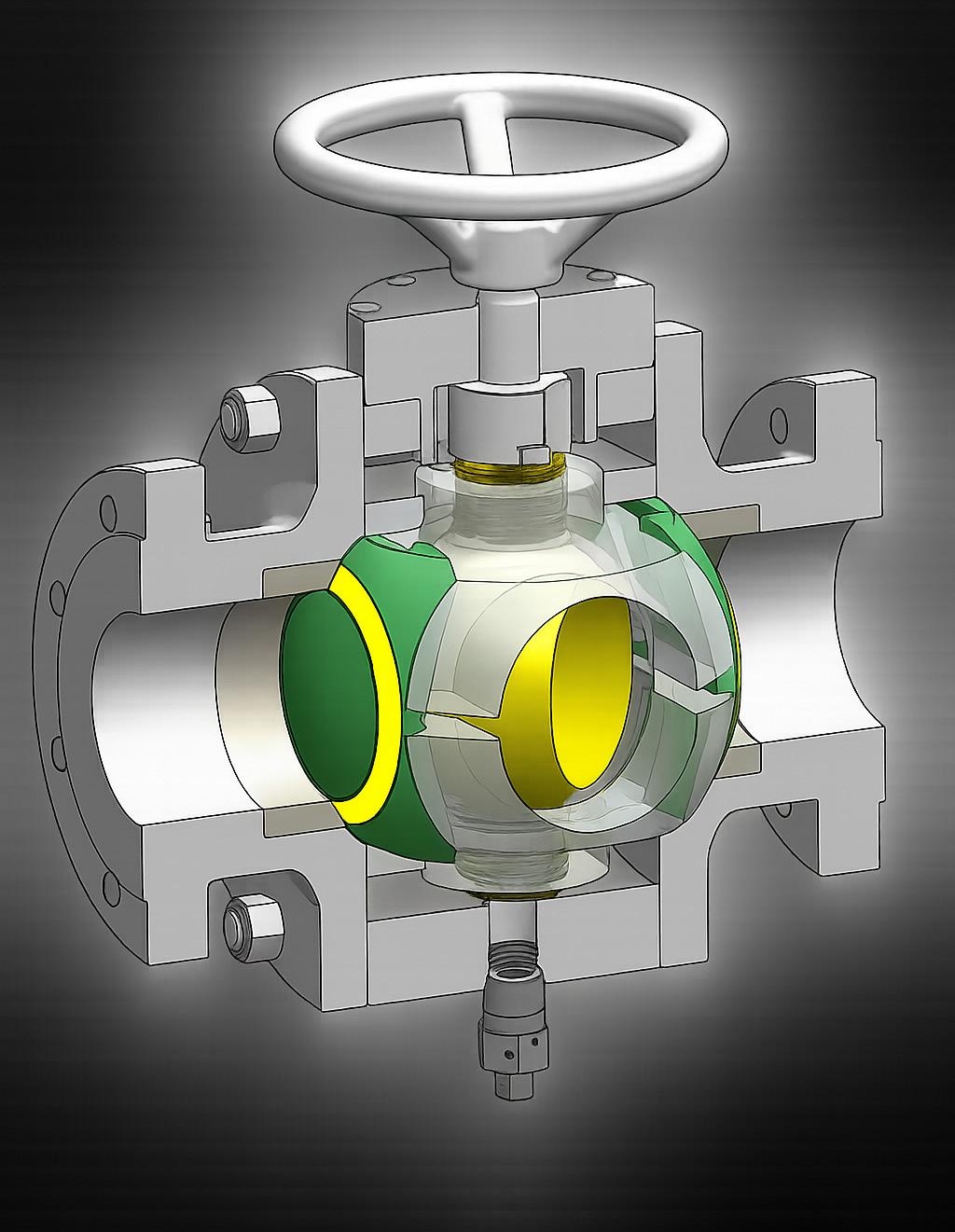
flanges and DB&B systems will also become increasingly more impractical and expensive.
Operators need to be proactive with regard to reducing emissions as opposed to reactive. There is a renewed focus on simplification and eliminating unnecessary interfaces as a basis for emission control.
Apart from safety and emissions, there are many unnecessary complexities and costs associated with traditional isolation assemblies. For example, DB&B designs have several valves, flanges, gaskets, studs nuts, and bleed piping. Their installation requires strict alignment and torque sequences, which have an added cost of materials, man-hours, and chances of improper setup.
From a lifecycle perspective these assemblies require ongoing services such as inspection, leak detection, and valve maintenance. Access and maintenance costs associated with these connections, particularly in offshore and remote locations, are very high.
A number of recent published project case studies demonstrate a simplification of valve assemblies at a conceptual level will reduce cost by as much as 30 - 40% while at the same time enhancing reliability and safety.
The problem with single blind flange and DB&B connections is not the workmanship and procedures. The issue is based on its design philosophy. Conventional isolation involves several components working together for its given functionality which is then incorporated into a unified system.
Pipeline design emphasises safety and is focused on minimising risk. From an isolation perspective, it means minimising pressure at interfaces and eliminating the need for opening flanges.
A number of operators have begun working on updating their internal engineering standards with regard to single blind flange connections. They are either making it prohibitive or non-preferred except in necessary projects and high-risk applications.
The role of integrated isolation technologies
Valve and isolation technologies have progressed to enable more integrated systems with new implications on how isolation can be realised. The approach no longer requires isolation capabilities to be assembled with multiple components outside but instead integrates isolation verification and pressure functionality into a single valve.
A case in point would be the BridgeFlow Valve, which has been designed precisely with a focus on eliminating the need for external flanges and DB&B assemblies. The innovative solution includes a barrier that enables positive isolation on both sides without either opening the pressure boundary or using external bleed valves.
By eliminating paths for leaks outside the valve it directly reduces fugitive emissions. The single-body valve


also eliminates failure points common with gaskets and lowers the costs associated with installation.
Moreover, this method provides a fully passive mechanical solution, incorporating optional tag-in and tag-out accessories. It exceeds current safety and emissions standards while maintaining the high reliability expected of traditional pipeline systems.
An integrated isolation system presents various benefits to the workforce. The removal of flange breaking operations lessens employee risk from high energy releases during maintenance and modification procedures. Employees will not be required to relieve bolts in the vicinity of trapped pressure.
It has been highlighted in recent safety notices that the most serious accidents have occurred during normal operating and maintenance procedures. New isolation technologies remove these risks and eliminate the need for any operator intervention at flanged connections.
Reduced contact with pressure boundaries within offshore operations, which have limited access and complex emergency response, becomes more desirable. Easy isolation helps make rig and barge operations safer and allows localised shutdowns as opposed to total depressurisation.
As governments and regulatory agencies tighten methane intensity goals, pipeline operators are finding it increasingly challenging to showcase measurable cuts in emissions. Adoption and usage of technologies are emerging as a differentiating factor among pipeline operators.
A unified isolation strategy fits more closely with efforts for decarbonisation because it removes sources of emissions instead of trying to detect and counteract them. It also builds compliance with regulations and financial interests associated with ESG.
A number of recent published articles have pointed out that emissions reduction via design optimisation will frequently produce more rapid and enduring outcomes compared with
solely operational projects. By shutting down leakage paths within designs there will be no need for constant repair and reporting.
Elimination of single-flange and DB&B connections would not demand a complete replacement of existing infrastructure. Adoption on a more application and risk-specific basis can be initiated.
The operators can begin with identifying the regions where frequent maintenance operations pose high emission risk or have limited accessibility. New projects and brown field developments offer opportunities to incorporate isolation technologies without interfering with existing infrastructure.
The next key step will be an upgrade on engineering standards and specifications. By articulating specific expectations with regard to simplification and isolation integrity, operators will be able to encourage widespread adoption.
Involvement with EPCs and skid builders also needs equal consideration. It will help to incorporate integrated solutions into designs and cost estimates at an early stage instead of considering any changes at an advanced stage.
The pipeline industry stands at a crossroads. The intersection of safety standards on emissions, cost constraints, and safety demands focuses a spotlight on traditional piping design practices. Single blind flange and DB&B assemblies have been viewed as optimal designs but are no longer seen as unnecessary risk sources.
Contemporary integrated isolation technologies prove that safer, simpler, and lower emission solutions can be not only achieved but commercially better as well. It will soon be seen that the industry is on a path towards safer pipeline systems as more operators start practicing these methods.
The removal and replacement of legacy isolation solutions present a tangible and worthwhile opportunity to mitigate worker risk, lower emissions, and reduce costs. It is an area that represents progress based on sound engineering knowledge and experience.
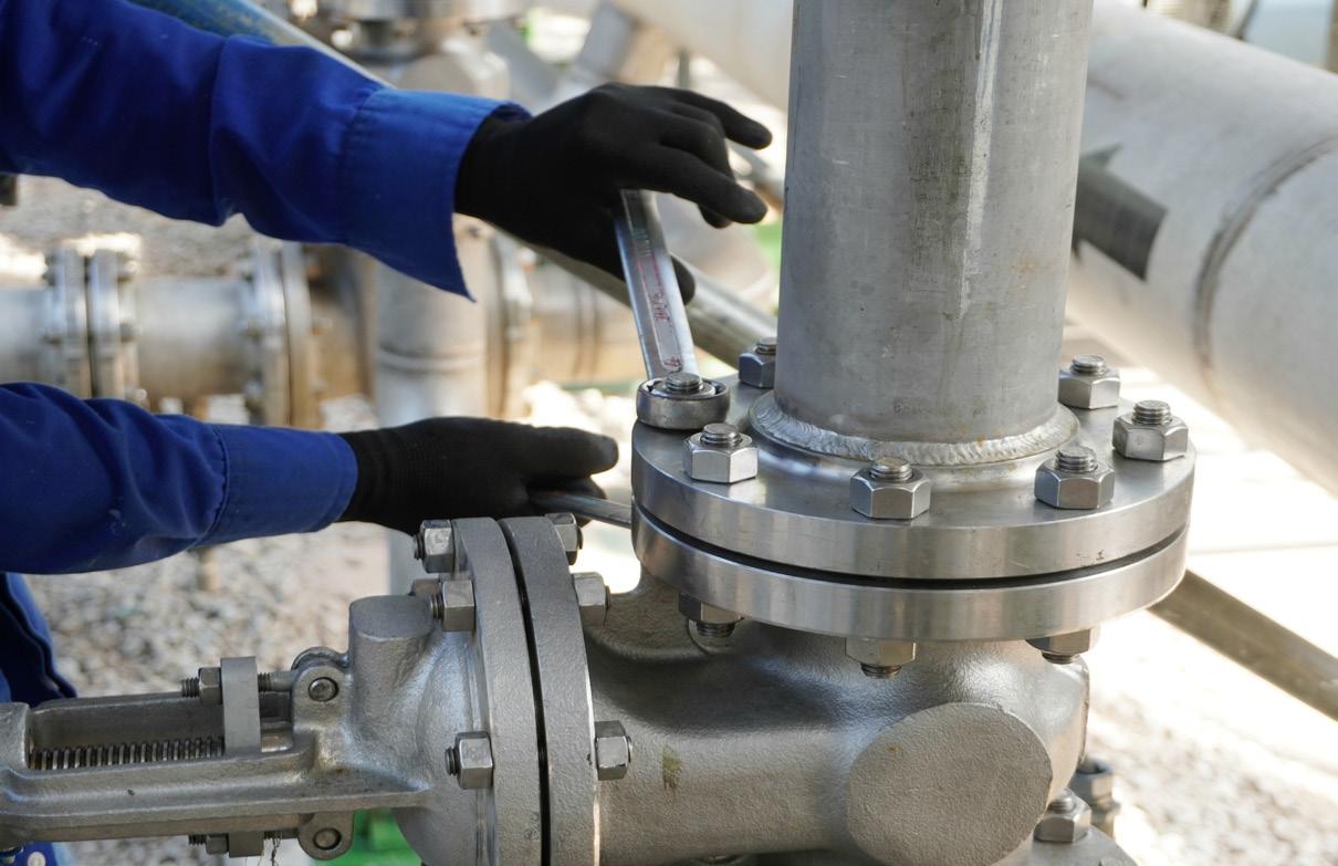
The regular use of single blind flange and DB&B connections serve as an added risk that pipeline systems do not need to be exposed.
Regular incidents within various industries, regulatory pressures, and safety emission rates seem to agree by adopting design simplification, better isolation practices, and technologies like the BridgeFlow Valve, these deficiencies can be eliminated at the source. It will enable a safer operation, lower emissions, and a more reliable pipeline system.
Looking ahead, it becomes clear what needs to be done. It is no longer an option but a requirement that unnecessary interfaces be eliminated and safety be engineered into the system.

Gary Burns, Technical Director, BEL Valves, UK, talks about the pressures involved in ensuring these safety critical products can be installed with confidence and will operate without risk of failure.
Valves play a vital role wherever they’re installed – controlling and isolating fluids and gases at extreme pressures and temperatures in a variety of different installation locations.
The most common places you’ll find our valves and actuators in use are in offshore topside facilities and deepwater production systems; and subsea manifolds and pipelines; our safety critical isolation valves are used for high integrity pressure protection systems (HIPPS), emergency shutdown (ESDV), boarding shutdown (BSDV), and subsea isolation (SSIV).
The installation locations, product type and size – we’ve manufactured valves from ½ in. diameter right up to 56 in. – may differ greatly, but the common ground they all share is that they need to be uncompromisingly reliable, as they are there to safeguard operations, people, assets and the environment.
That translates to a lot of pressure on each and every valve, and so it’s clear that the standards they’re manufactured to need to be exacting to say the very least. And when you consider just what we need to comply with, it’s clear that no stone has been left unturned.
Our valves are engineered to comply with a variety of requirements, which can comprise BS, EN, API and ISO series’ standards (e.g. API 6A, 6D, 6DSS, 17D; ISO 15848, 10497); UK Pressure Equipment Safety Regulations (PESR); the European Pressure Equipment Directive (PED); relevant regional
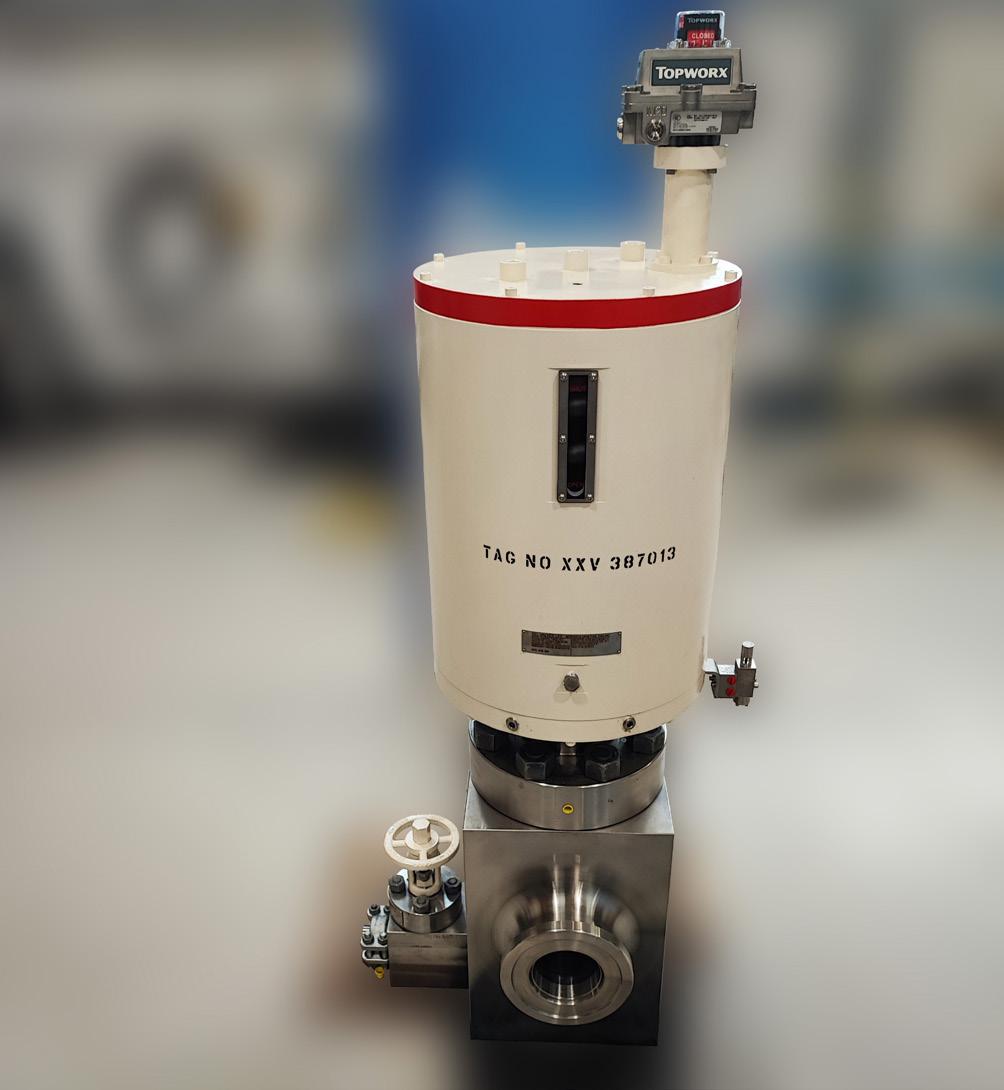
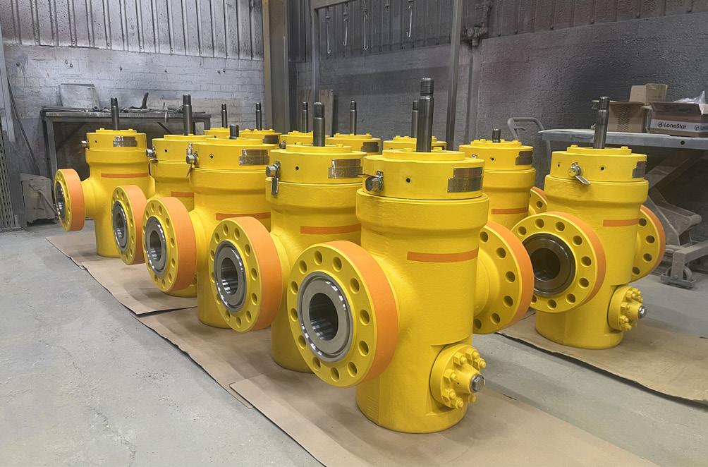
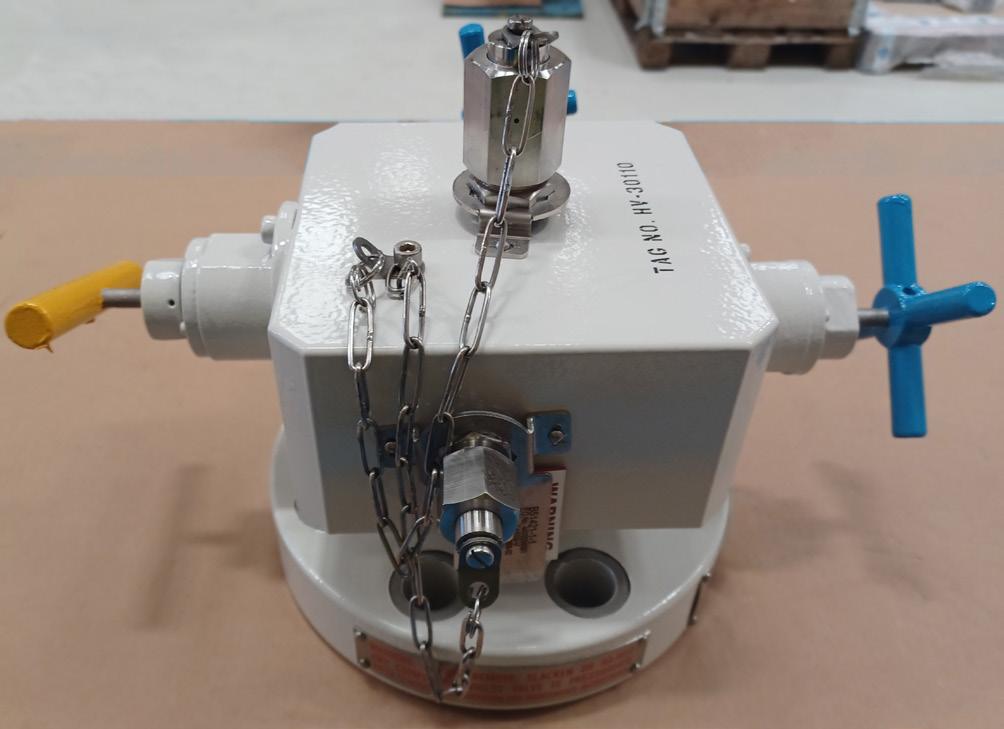
specifications such as NORSOK; and any client/end userspecific requirements.
To achieve this, BEL Valves’ valves undergo a tailored sequence of qualification and production tests depending on end use and function, which can comprise:
) Hydrostatic testing is crucial in ensuring the safety and reliability of pressure systems. It involves filling the system with water and applying pressure, typically at 1.5 times the rated working pressure, and checking for leaks or deformation. It’s carried out to provide confirmation that the equipment can operate to its required limits.
) Gas testing confirms a valve’s leakage performance at the seats, stem packing and pressure retaining joints as well as through wall leakage to defined limits, ensuring it seals properly in service. It uses air or nitrogen to verify sealing integrity because gases are compressible and can reveal finer leak paths than water. Gas tests validate real world performance and often detect leaks that a hydrostatic test may not.
) Fugitive-emissions testing assesses leakage to atmosphere from the stem packing and body joints under pressure and thermal/mechanical cycling. Most often performed with helium as the test medium, its small molecule size reveals ultra fine leak paths. It demonstrates environmental compliance and low emission design.
) Endurance/cycle testing evaluates the performance and durability of valves by subjecting them to repeated opening and closing cycles under strictly controlled conditions. The testing is essential for identifying potential failures and ensuring the valves will withstand the demands of their intended applications.
) Hyperbaric testing verifies valve integrity and operation under pressures simulating subsea depth. In a pressure chamber, the valve is cycled and checked for ingress (external to internal) and egress (internal to external) leakage, plus actuator performance, proving sealing and function at depth.
) Temperature testing assesses the performance of valves in extreme temperatures – typically from cryogenic lows of -150°C to extreme highs of 315°C.
) Fire testing, as the name suggest, is carried out to demonstrate a valves ability for containment and operability under fire conditions.
If that wasn’t sufficient, advanced non-destructive examination (radiography, ultrasonics, PMI, dye-penetrant and more) supports each stage of manufacture. Along with safety integrity level (SIL) capability assessments for our safety critical valves and actuators.
All type, qualification and factory-acceptance testing is carried out in our purpose-built, high-integrity facilities in Newcastle upon Tyne. This means we’re in a position where feedback on testing is rapid and continuous improvement is a key element of the product development lifeline of every single valve we design, engineer and manufacture.
And we don’t merely comply with regulations; we frequently surpass them. For projects with extreme operational scenarios – ultra-deepwater or hydrogen service, for example


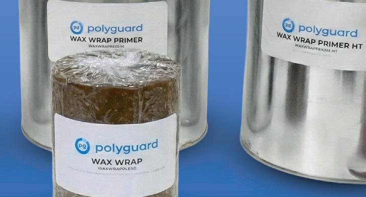

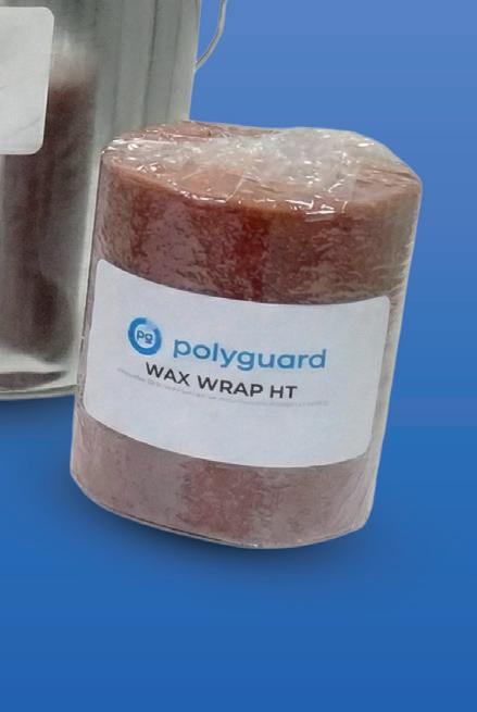


– valves are tested well beyond the minimum requirements. Working closely with clients, we design bespoke type tests that replicate field conditions more severe than any standard demands.
Of course, not every product we test ends in success. Occasionally a prototype is pushed past its limits – that’s the point. Whether it’s minor seat leakage or unexpected actuation torque, every anomaly feeds directly into our continuousimprovement loop; driving the development of safer, more reliable products.
The world though doesn’t stand still and so the onus is on manufacturers like ourselves to keep pace with technological developments and changing industry requirements. The shift towards hydrogen, CO2 and, other low-carbon fluids is certainly the key focus for us, our competitors and the industry as a whole and is one that is being discussed amongst various industry working groups – the majority of which we participate fully in. The aim of them all being to identify and develop new working practices and drive standardisation – ensuring all new
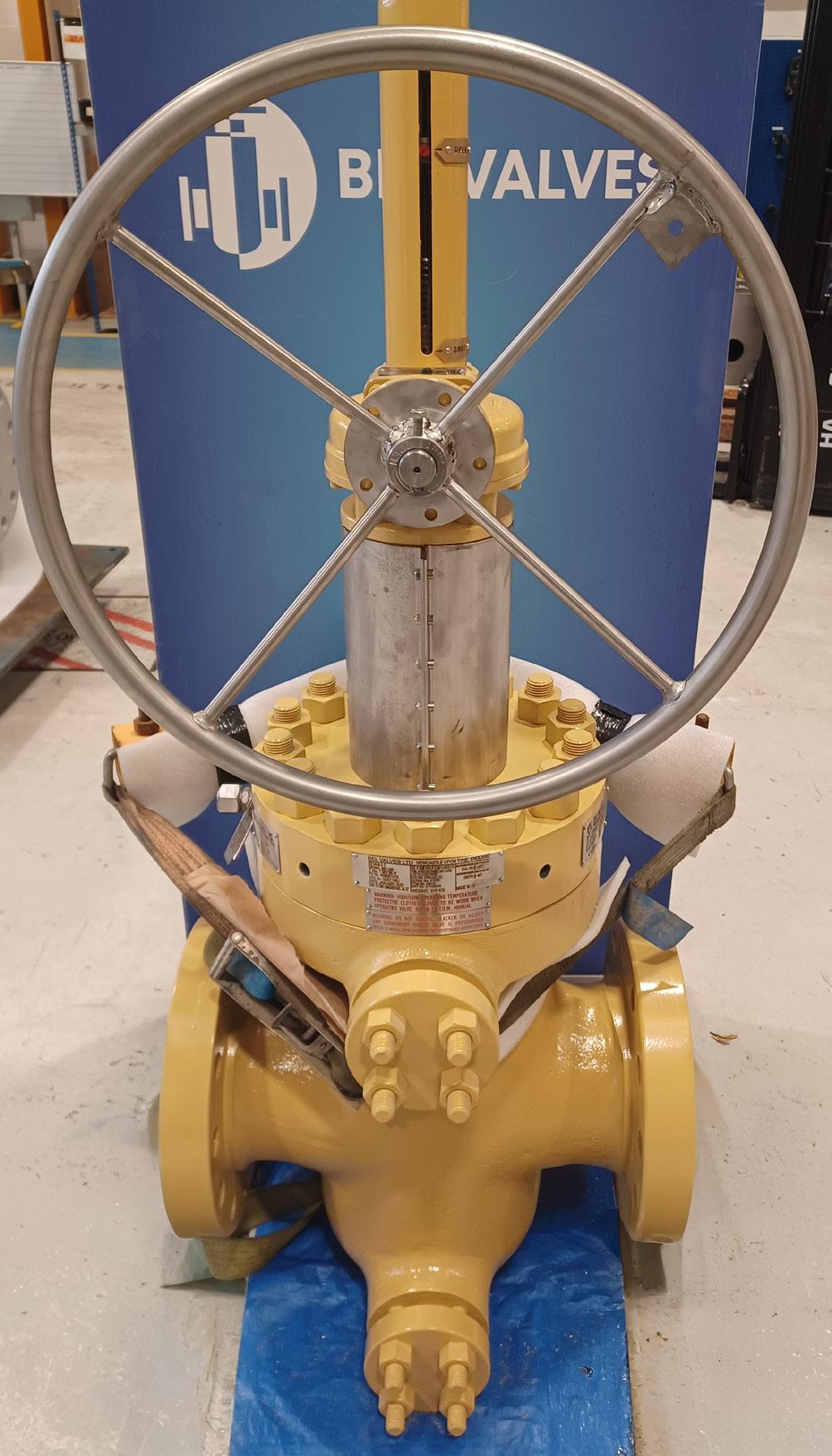
standards are created by those who can rightfully lay claim to being experts in the field.
At present, the creation of valves that deliver greater control of seat leakage and tight shut-off performance; fugitive emissions; fire safety; and metallic and nonmetallic material qualification is high on everyone’s agendas.
What’s certain during this period of change is that new standards will be developed and ratified, new products engineered and existing ones modified – ensuring the safety critical operation of the valves used in these high value, high importance installations is never compromised.
We manufacture high integrity valves, complete with actuation and control systems for oil and gas and hydrogen and carbon capture installations – and our products are in demand around the world. Most recently we designed, developed, manufactured and supplied bespoke small bore needle valves and gate valves for two major North Sea oilfield developments.
The valves were specified by Subsea7 for Dana Petroleum and Serica and have been installed on subsea elements of the Belinda and Bittern oilfields, both of which are situated 190 km east of Aberdeen and will supply the Triton floating production storage and offloading (FPSO) vessel when they become operational in early 2026.
Designed for heavy duty on/off applications in the challenging subsea environment, our subsea Gate Valve range can be supplied in bore sizes from ½ in. to 36 in. Meanwhile, our Needle Valves suit bore sizes of ½ in., ¾ in., and 1 in., and have a pressure rating up to 15 000 psi.
The performance of these products is guaranteed by the tests they were put through prior to being put into production. This included hydrostatic and submerged gas shell and seat testing in full compliance with API 6A PSL 3G – including the stringent zero allowable leakage requirement. These factory acceptance tests are supported by earlier validation of the valve types, with 600 endurance cycles incorporating temperature and hyperbaric cycling.
It wasn’t just product performance that secured the Subsea7 order. Our ability to deliver fast-track orders and meet lead times far shorter than our competitors played a huge role in landing the order. As did our provision of full life cycle support on all products.
A BEL Valves valve embodies decades of engineering expertise, a culture of safety and relentless innovation. By exceeding global standards, pioneering new test methods and validating performance under the harshest conditions, the company fulfils one simple promise – its vales are safe, reliable and built to last.
Founded in 1964, BEL Valves is a global leading manufacturer of high-integrity oil and gas valve technology and is looking to replicate this success across carbon capture and hydrogen services. The Newcastle, UK-based company is renowned for the durability and performance of its bespoke products, its fast lead times, full life cycle service options and tailored engineering solutions.
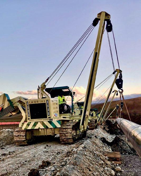
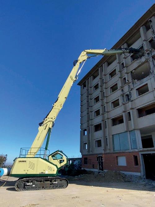
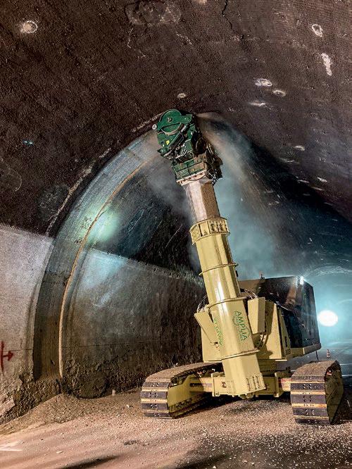
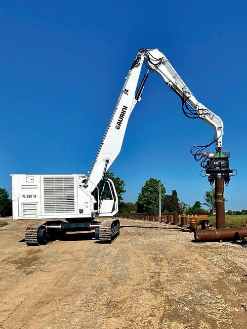
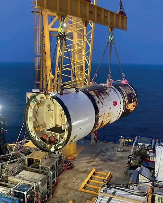

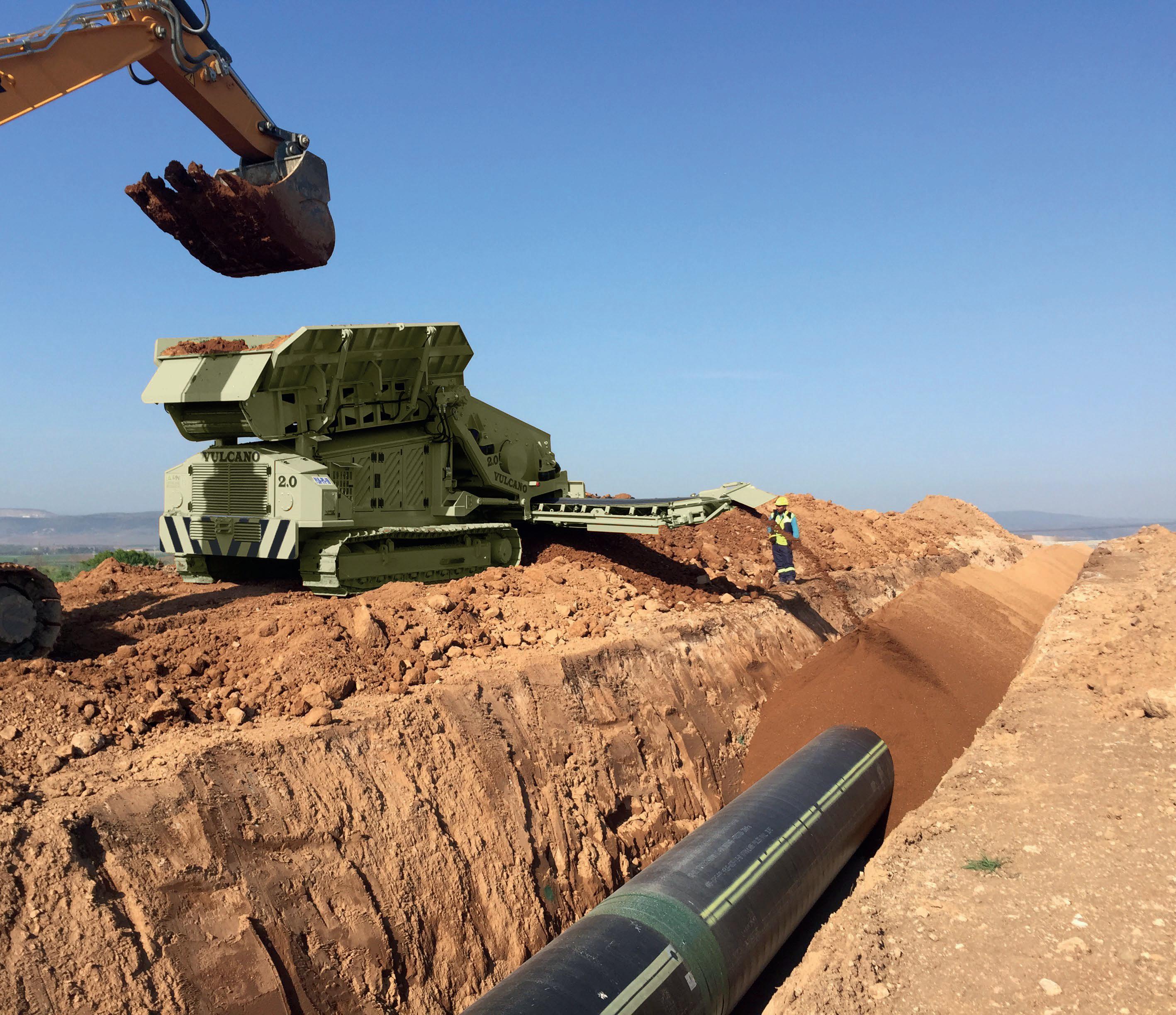


remote control The material is fed by means of an excavator The screen grids are interchangeable, and the apron feeder is speed adjustable The side-to-side rear conveyor belt is retractable and foldable These features together with the high reliability make Vulcano a versatile machine, fitting for any sort of soil and suitable for different right of way conditions VULCANO SMART is the more compact version, while VULCANO XXL has the highest productivity





Cassandra K. Moody and Chelsea La Salle, Time For Change Engineering, USA, explain how pipeline and facility operators can improve their asset integrity management programmes using a straight forward approach: the ADD method –Assess, Design, Do.
Asset integrity is a complex, expensive, and timeconsuming aspect of a pipeline system, but it is vital to operate safely and ensure reliability. Does your company face any of these problems regarding pipeline and facility integrity management systems?
) Lack of time.
) Lack of expertise among in-house company personnel.
) Insufficient number of personnel resources.
) Competing priorities of safety and budget.
The solution to this problem is simple: an integrity programme focused on right-sized solutions to your regulatory compliance needs. The first step in this programme is prioritisation. If you do not have the resources or expertise

in-house to assess the entire programme, then you can use the quiz in Table 1 to help focus your yearly review, and to provide an assessment of your current integrity management programme. For the assessment and improvement of your integrity management programme, use the ‘Assess, Design, Do’ (ADD) method!
The ADD method
The ADD method is a simple way to assess and improve your integrity management programme. The ‘assess’ portion involves analysing your assets, including your current integrity management programmes. The ‘design’ portion involves scheduling future activities, such as remediation activities. The ‘do’ portion involves implementing any changes to your
integrity programmes, and completing any scheduled activities. It is important to note that this is not a linear process, as shown in Figure 1. As circumstances change, such as a leak, your priorities need to shift.
Using Table 1 can assist you in focusing your yearly review, and to provide an assessment of your current integrity management programme. For each question, select one of the three answers that you believe aligns with your company’s current asset integrity programme. Based on your selection, put your score for that question in the ‘your score’ box for that row. After answering all the questions, add up your points to determine which tier your company’s asset integrity programme falls into.
The ‘assess’ activities are critical to the completion of the ‘design’ and ‘do’ phases of the asset integrity quiz. Informed decisions ensure that the proper priorities are set. Without proper prioritisation, essential tasks – like repairs – can be overlooked or delayed, increasing the risk of an incident. The following actions should be completed in the ‘assess’ phase of the asset integrity quiz:
) Compile a list of all assets.
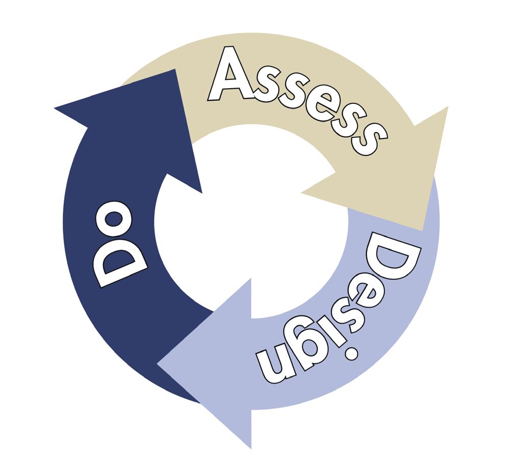
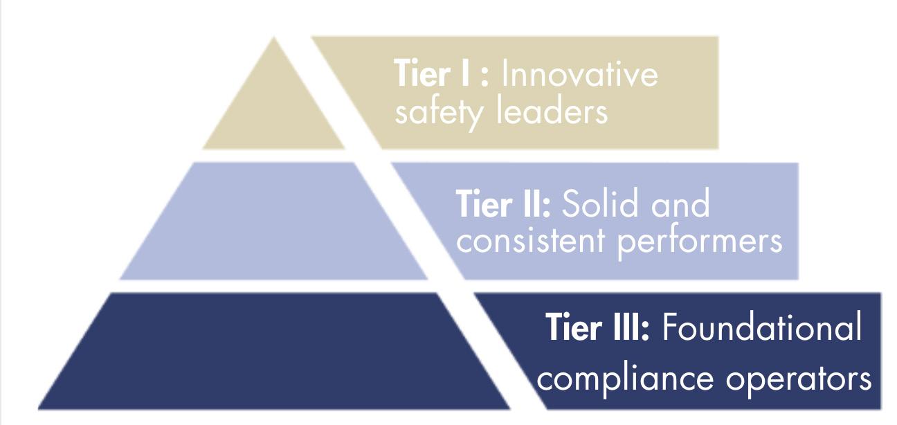
) Identify, assess, and compile a list of the threats to each asset.
) Identify the threat level of each asset to the surrounding area.
) Assess the risk of each asset.
) Review current integrity assessment plans and programmes.
) Analyse current trends in industry and regulatory notices.
) Determine the need for any remediation activities, mitigative activities and/or any additional activities.
) Using the actions above, determine the integrity of each asset and prioritise the list of required activities. Documented Asset Integrity Plans, per asset, are common for Tier II and Tier III operators.
An example of the type of trends to analyse can be seen in Figure 3, which shows the flagged incidents categorised by eight common causes of incidents for gas distribution pipelines. These trends published by PHMSA indicate not only the most common causes of incidents, but assist in prioritising which threats to address during the ‘design’ and ‘do’ phases. When beginning a fresh ADD Method review of an integrity programme, starting with industry data is a reliable starting place in the absence of accurate or complete operator data. The quality of the completion of each stage is an indicator of the tier an operator falls into. For an operator initially employing the ADD Method, consider completing the foundational compliance items listed in Tier 3 before aiming at tackling Tier 2 activities. An example description for each tier from the integrity assessment for the ‘assess’ phase is as follows:
) Each individual asset has documented and up to date asset integrity plans with detailed risk and threat analysis.
) All of the company’s assets, both jurisdictional and nonjurisdictional, are included in the risk method assessment and results drive informed decision-making leveraging data analytics and operator knowledge.
) The operator has systems in place to collect and update reliable data to be used in predictive analytics to identify potential integrity concerns well in advance of anomalies becoming critical conditions.
) Threat assessments of individual assets are incomplete or outdated.
) Only some assets have asset integrity plans documented, perhaps just those in High Consequence Areas (HCAs).
) The risk assessment methodology is present, but does not produce meaningful results to drive decisions.
) Assessments and repairs are mostly reactionary, but are completed on time with documentation.
) Operator does not have an asset list available and jurisdictional determinations are incomplete.
) There is not a single, reliable schedule for their required integrity assessments.
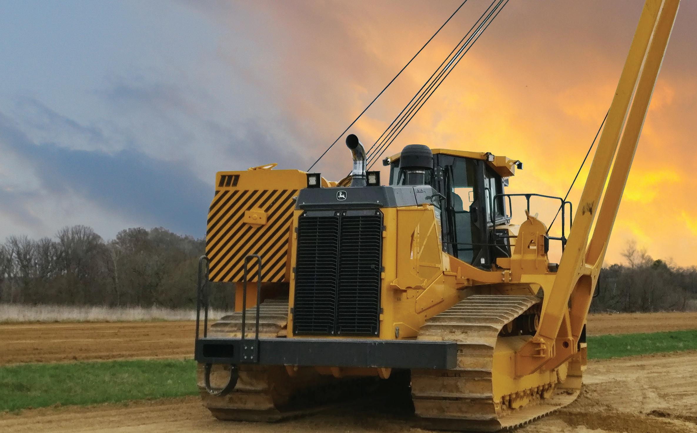


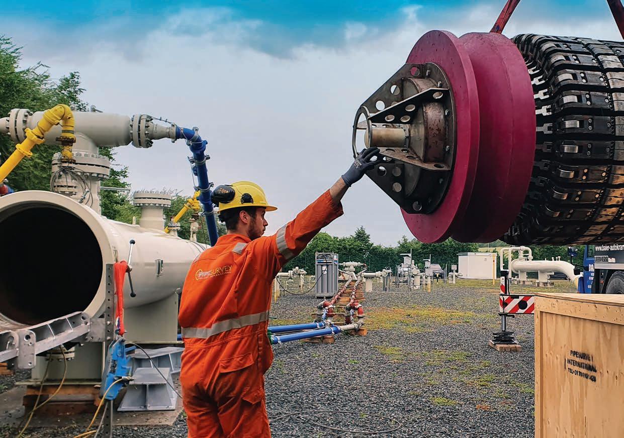

) Specific threats to assets are unknown.
) The operator does not have or use an effective risk methodology in place.
Plan any inspections/reporting that are necessary for the year, prioritising required timed conditions. Proper planning is essential to completing any integrity-related activities. Whether it is reporting to a government agency or making required repairs, planning ensures your company maintains regulatory compliance throughout the year while realising cost-savings where possible. See below to know what tier your company falls into during the design phase:
Innovative operators leverage emerging technology, such as artificial intelligence (AI) tools, to prioritise and evaluate digs to prevent unnecessary digs, and predict problems before they arise while still ensuring all assessment requirements and repairs are completed in a timely manner. Their procedures are detailed and cross-reference procedures across the company, avoiding silos in activities and data which directly impact integrity performance.
These operators are consistent by leveraging the right tools to assess for specific threats, and coordinating efforts to accomplish their goals. For example, they are intentional when scheduling in-line inspection (ILI) verification digs to coincide with digs to meet new mega-rule MAOP Reconfirmation and Material Verification requirements. Cost savings are
What is the status of your company’s procedures?
What is the status of your company’s data records?
Basic code-regurgitation procedures saying ‘what’
Records are incomplete with siloed and unorganised data
realised in these planning instances. Another example includes specialised threat-specific ILI tools for crack and geohazard threat management are deployed. Procedures exist but do not cross reference other functional groups within the company. Redundant activities and data sets exist.
These are ‘Pig and Dig’ operators. These operators schedule the minimum required assessments and repairs per the prescriptive regulations. Procedures simply copy the minimum requirements and do not provide detail on how activities are conducted.
The final phase of the ADD method is the implementation of all necessary changes. The following actions are required for the completion of this phase:
) Implement any changes to the integrity programmes/plans.
) Complete all scheduled activities from the ‘design’ phase.
) Schedule a check-in with the operations team to determine the effectiveness of changes.
) Address any emergent projects, such as addressing an incident or audit-findings.
) Attend industry organisations to share lessons learned with other operators.
Without action, even the best integrity management plans become meaningless. Having procedures in place without the proper execution and training in the field is an opportunity for negative audit findings and may lead to incidents. Followthrough of your plans is the only way to safeguard our communities and the environment. Ensuring the IMP are
Some written procedures without cross-references to other documents identifying ‘what’ and maybe ‘who’.
Records are decent and data is located in a single database
Comprehensive procedures stating ‘who, what, where, when, why, and how’ that cross-reference other documents, and are annually updated
Records are in great shape, TVC accuracy, and well organised across the organisation with visualisation
How many incidents has your company had in the last 3 years? > 5 incidents 1 - 4 incidents 0 incidents
How many state and/or federal inspections has your company had in the last year? < 10 inspections
How many assessments (ILI, Hydro, etc.) does your company conduct per year on average? < 5 assessments
- 20 inspections
21 inspections
- 50 assessments > 51 assessments
Which option best describes your company’s risk management programme? SME qualitative programme Semi-quantitative or QRA programme
Which option best describes your company’s training programme? Basic training
Moderate training with hands-on skills assessments
Comprehensive risk and threat management program with meaningful results and riskinformed decision making leveraging data analytics
Industry-leading training and proactive table-top drills
Note: this assessment is for informational purposes only, based on self-reported information Total points Grading
right-sized and compliant through risk-informed decision making, prioritisation, and planning can help your operation realise cost savings. Take action and be a Tier I operator:
Operator is an active industry leader in regulatory and standards committee development and industry conferences. The supporting teams including operations, corrosion, integrity, risk, information technology, and capital projects work cooperatively and often as part of an effective Management of Change (MOC) process. More often than annually, procedure changes, lessons learned, and integrity-focused initiatives are proactively discussed throughout the company. Company performance metrics are meaningful and show results over time. The operator has developed specialised programmes to target real threats to their assets and have the resources to support such efforts for deadlegs, geohazard threats, Process Safety Management (PSM), facilities, corrosion, and cracking. The proactive safety leader, conducts its own in-house audits to ensure proactive compliance and results from their asset management programmes.
The operator completes inspections, repairs, and a few resulting preventative and mitigative measures (P&MMs). Company performance metrics are not integrated in company activities. Communication of integrity activities is fragmented across the company. A basic annual review of programmes and procedures is conducted and documented. The operator attends and participates industry events. Audits by regulatory bodies and incident responses are reactionary, but with few findings. Many opportunities for improvement, efficiency, and risk-informed decision making across the company exist.
The minimum foundational requirements copied from the applicable federal regulations are met. Documentation of operator activities and records are lacking. The activities conducted remain within the operational silo of the company without leveraging other group’s perspectives. Industry participation, lessons learned, and incident response are lacking. While the minimum safety standards pipeline and facility operators face coupled with their own company policies and procedures may seem overwhelming, by taking a systematic approach towards continuous improvement of an asset management programme, progress can be realised and measured to evaluate a company’s investment. A sample 12 month approach to the ADD Method of an operator’s programme is provided on the following page. The activities suggested within the three stages of the ADD Method are spread out over a
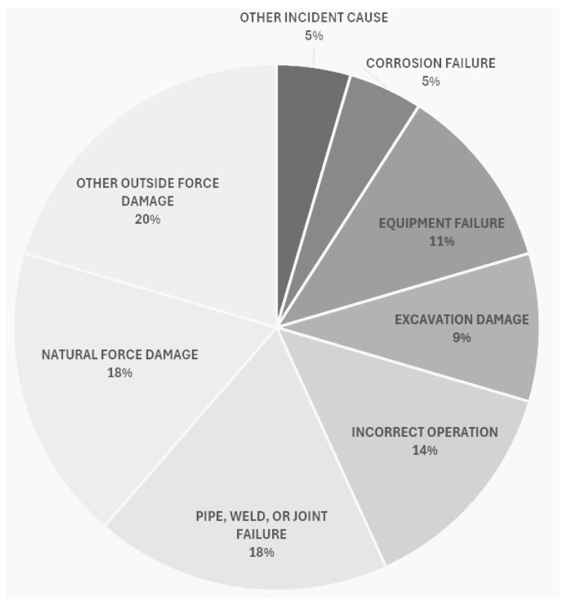
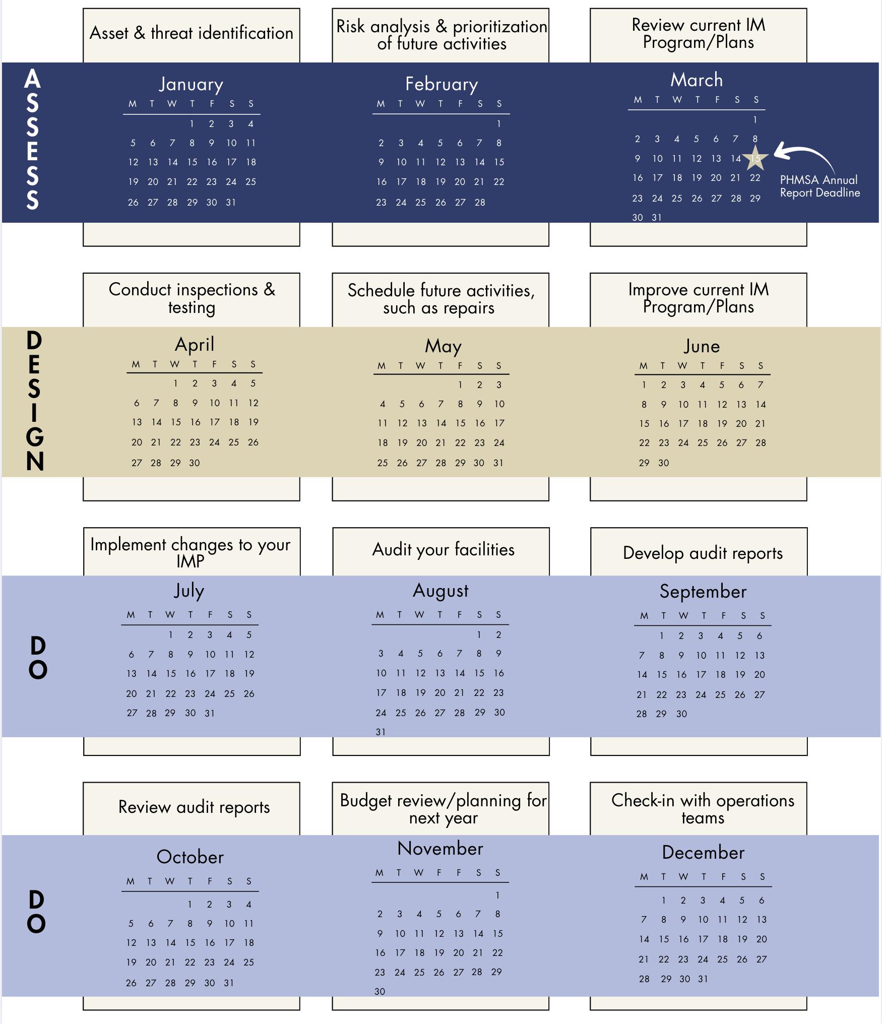
year as a starting point to improve an asset management programme. The specific activities for each operator tier can be employed to progress an operator from a lower tier, to a higher tier depending on the individual areas for improvement identified during the ‘Assess’ stage. Of course, as emergent activities, such as leaks, incidents, inspections, or audits arise, attention will need to pivot to ensure issues are adequately addressed. Documentation of any resource gaps to meet these requirements can be presented during the subsequent budget review cycle.
Asset integrity ensures the safe operation of pipelines and facilities, but it can be complex to implement in practice. If your resources are limited or you need a fresh set of eyes to review your programme, you should reach out to experienced help. Both the pipeline safety regulations and the Occupational Safety and Health Act (OSHA) for general duty have been in place since the 1970s. The PSM regulations for facilities involving highly hazardous chemical became effective in the 1990s. There is no need to reinvent the wheel when it comes to ensuring your company’s operational safety philosophy and asset management programmes. Leverage industry knowledge, expertise, and lessons learned to improve your company’s programmes.2, 3, 4 Even seemingly small, incremental efforts over time snowball into a proven track record of safety and success. Oftentimes selecting what small effort to improve on first is overwhelming and leads to inaction. Consider for
a moment the most glaring area of improvement in your integrity management programme. Has a new acquisition led to a set of unintegrated assets with unknown threats and risk? Is a consistent and meaningful risk methodology in place to guide informed decision making? Are persistent failures from a particular threat or deadlegs plaguing operations? Are inadequate records leading to overly conservative data assumptions in your risk programme? Once you identify an opportunity for improvement (OFI), brainstorm a few achievable activities, perhaps suggested in the operator tiers. Block out a time on your calendar to tackle just one of these activities or formulate plan to apply the ADD Method to your OFI. Once completed, celebrate and use the momentum of completing one OFI to chart the course for being a Tier I innovative safety leader. John F. Kennedy used the phrase, “a rising tide lifts all the boats” which couples with PHMSAs industry-wide safety improvement culture. By applying the ADD Method to your company’s operation of pipeline and facility assets, you can help rise the tide along with other responsible operators to achieve a favourable investment.
1. https://www.phmsa.dot.gov/sites/phmsa.dot.gov/files/data_statistics/ pipeline/PHMSA_Pipeline_Safety_Flagged_Incidents.zip Pipeline Hazardous Materials Safety Administration (PHMSA)
2. 49 CFR Part 192 November 12, 1970 35 FR 17658 (Federal Register, Vol. 35, Page 17658) 49 CFR 195 April 1, 1971 36 FR 4591 (Federal Register, Vol. 36, Page 4591)
3. OSHA General Duty April 28, 1971, (Public Law 91-596, 84 Stat. 1590)
4. 29 CFR 1910.119 May 26, 1992 57 FR 6356 (Federal Register, Vol. 57, Page 6356)




Hydrogen compression explained: why hydrogen is uniquely challenging to compress, what that means for compressor design and pipeline build-out, and how advanced materials could help unlock viable large-scale networks. Featuring Dr Samuel Stutz, Global Technology Manager, Greene Tweed.
We cover:
• Why hydrogen compression is different from natural gas compression.
• How composite technology supports hydrogen power applications.
• How we make hydrogen networks more economically viable.
• Advanced materials testing, and designing hydrogen infrastructure for the long term.

Neil Wilds, Global Product Director of CUI/Testing, Sherwin-Williams Protective and Marine Coatings, explains how advanced thermal insulation is helping the oil and gas industry prevent costly corrosion under insulation.
Corrosion under insulation (CUI) is a pervasive yet often unseen challenge in oil and gas facilities. As any facility operator knows, it raises significant safety, economic, and operational concerns, all of which have potentially devastating consequences.
Data shows that the insidious threat of CUI has played a part in more than 20% of the European Union’s major oil and
gas accidents since 1984, and in around 60% of pipe failures within the UK Continental Shelf (UKCS).1 Not only do such incidents have heavy financial costs, but they can also put personnel in harm’s way – something operators world-wide are committed to avoiding.
Traditionally, the industry has relied on expensive, time consuming, error-prone monitoring schedules to keep CUI in check. Yet even with these mitigation strategies in place, corrosion will, inevitably, win the war.
Now, a new emerging approach could spell the end of this never-ending battle. Because today’s advanced thermal insulation coatings will not just reduce the risk of CUI, but actually eliminate it and all its associated threats.
In this article, Neil Wilds, Global Product Director of CUI/Testing at Sherwin-Williams Protective and Marine Coatings, explains what this technology is, how it works, and
how it can give facility operators the edge in the ongoing fight against CUI in oil and gas facilities.
Many oil and gas processes require process contents to be kept at specific temperatures. Natural gas products for example, often require chilling to condense them for separation and transport. Another example is crude oil, which tends to be heated in order to reduce its viscosity and allow it to flow through pipelines.
Thermal management, then, is essential. By helping to maintain more consistent temperatures, it prevents heating and cooling processes from becoming inefficient, unstable, or even hazardous to workers.
Traditionally, operators have used conventional insulation materials such as mineral wool or calcium silicate, sometimes called lagging or jacketing, to protect their installations from the elements.
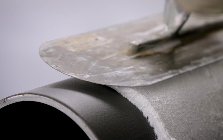
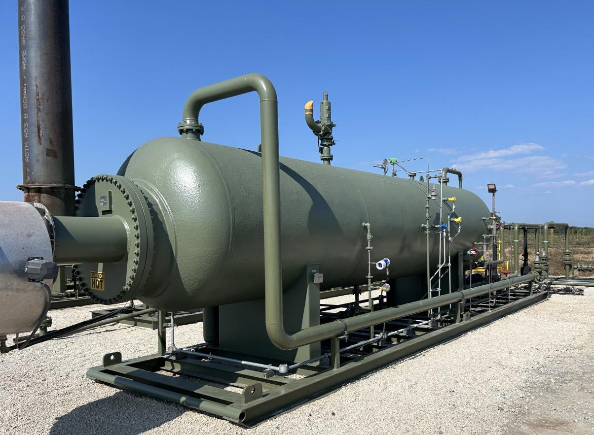
Yet this approach has its own, significant, challenges. Because installing complex insulation systems on valves and intricate piping configurations, for example, rarely results in a fully watertight assembly, making moisture intrusion common.
Water can enter the system from multiple sources, from plant drift to environmental exposure such as rain or coastal seawater. When moisture penetrates the insulation, it becomes trapped against the metal jacketing, creating a corrosive environment that is often hidden from view.
In the oil and gas sector, where insulated infrastructure is exposed to harsh environmental and process conditions, CUI can progress rapidly and lead to equipment failure. When this happens, consequences can include production downtime, safety incidents, costly repairs, and compliance risks. In extreme cases, it can even lead to staff fatalities.
For all these reasons, CUI mitigation strategies are common place. They tend to include regular monitoring, with the aid of non-destructive testing methods like ultrasound and radiography, as well as visual inspection. However, these methods are highly time consuming, expensive, and, at least to some degree, prone to human error.
For all these reasons, Sherwin-Williams has been working to re-evaluate the industry’s longstanding approaches to thermal management.
In recent years, many suppliers have used anticorrosive primers based on epoxy chemistries and micaceous iron oxide (MiO) pigmentation to reduce the risk of corrosion from CUI. However, the corrosion zone
underneath the insulation remains, alongside the associated costs of inspection and moisture-induced performance
Not only do they eliminate the internal moisture retention problem, but advanced thermal management approaches have

IPLOCA_Ad_60thAnniversary_Palladian_210x146mm_300dpi.pdf 1 16/02/2026 12:13





In many industries, the adoption of artificial intelligence (AI) has been unassuming and fast-paced. But when it comes to critical industries such as oil and gas, there are hesitations surrounding implementing new ways of working that could have detrimental impacts on worker safety and production. In this article, Jackie Hu, Chief Operating Officer at IMI plc and co-author, Michael Smith, Director, Data & AI at IMI plc, explain why the key to safe adoption of AI in such industries is humans.
The term AI is increasingly used in numerous settings and to refer to various software applications. At its centre, AI refers to machines that simulate human intelligence. Technically, this means basic computational algorithms can count as AI. Such tools have been a key part of engineers’ roles for some time, helping them to automate processes and perform calculations. Most engineering software used today, for example, relies significantly on rule-based methods to produce trustworthy results.

Today’s definition of AI has moved instead towards machine learning (ML) which uses statistical techniques to learn patterns from data rather than having to code every rule by hand. This method is boosted by powerful computing resources and large datasets which has led to impressive progress in sectors such as speech processing, predictive analytics, and image recognition. These advancements have opened the doors to agentic and generative AI.
Generative AI is capable of creating original designs, images, text, or code. The next step up from this is agentic systems which can plan, reason, and act with autonomy. Implementation of this technology in engineering is understandably reserved despite the significant potential of the systems because of the black-box and probabilistic nature of the AI tools.
Engineering issues are often safety-critical and complex, which is why explainability and precision are paramount. That’s why, rightly so, questions surrounding reliability, control, and safety are raised
Jackie Hu, Chief Operating Officer, and Michael Smith, Director, Data & AI, IMI plc, explain why the key to safe adoption of AI in is humans.
when the implementation of AI systems in the sector is discussed. It’s also the reason why, unlike in other industries, the technology hasn’t yet become a default solution for most engineering problems. The sector’s reluctance isn’t about resisting advancement, it’s about making sure innovation adheres to stringent human standards.
‘Discriminative’ AI is the most frequent kind of AI used in engineering today. It doesn’t create original outputs like generative AI, but instead it classifies data and makes predictions based on information already available. An industry example of this is a deep neural network which could analyse sensor readings to predict when a part could fail. Another could inspect new products on a production line and sort them as acceptable or defective. In both instances, the model is trained on previous data and applied to new, never-before-seen cases.
These technologies are very effective at tasks that demand creativity, synthesis, or complicated information administration. AI is already commonly used in pharmaceutical engineering to suggest novel molecular structures and propose potential drug recipients, speeding up the process for researchers compared with traditional approaches. The technology is also presently used in software engineering to expedite development, draft code, and enable programmers to concentrate on higher-level investigations.
Our internal chatbot at IMI is one example of how we are introducing generative and agentic AI in practical terms. It uses a secure large language model (LLM) and search index to help engineers with asking questions on our products, engineering know-how, and services. Technologies like this can also be used to interpret project specifications or complex datasheets. In addition, accurately designed AI agents can enable deeper data analysis, research, and problem solving. These systems speed up the amount
of time spent by engineers on manual, laborious tasks, allowing them to prioritise work on meaningful customer problems.
If we truly want to unlock the full potential of AI, we need to first empower people to be AI-fluent. Engineers need to feel confident in working alongside AI and be well-equipped with the skills they need to operate the technology in the most efficient way. This means they need to understand its limitations and capabilities, and to know when to trust it or question it. Fundamentally, engineers will be central in guiding and designing future AI technologies like agentic and generative systems. Engineers’ decades of expertise and experience will be mission critical in ensuring AI systems fulfil their potential.
Regardless of how AI is used – whether it be for fluid and motion control, programming or drug discovery – humans will be essential. It shouldn’t be forgotten that AI tools need prompts from a skilled engineer who can leverage the intended outcome. Any outputs also need to be proofed by a competent individual. This is because LLMs are programmed to create responses that seem genuine and sensical, but they do not guarantee certainty. Commonly named ‘hallucinations’ can produce information that seems realistic but is factually incorrect. In the instance of agentic AI, where the LLM ‘decides’ which action to take based on a

user’s input, these errors can have real-world and quite frankly critical consequences. By having a trusted pair of engineer’s eyes validate outputs, industry leaders can ensure engineering decisions remain dependable, accurate and safe.
It’s our view at IMI that the successful adoption of AI in engineering will directly correlate with the advancement of the engineer’s role. In this instance, we can look at the field of Data Science for inspiration which emerged as a recognised discipline in the early 2000s. The field combines programming, industry knowledge, and statistics to develop models and extract findings from data. Taking this into consideration, the role of the modern engineer may also need to evolve, putting greater emphasis on programming, data literacy, and AI-specific skills, including agent building and prompt engineering.
Predictions suggest that the UK will need up to 1 million more engineers by 2030 to fulfil present vacancies, and 59 000 new engineers per year to meet the demands of the green economy.1 With the sector set to become increasingly AI-enabled, this next generation of installers will need to be filled by AI-fluent people.
Our Early Careers Conference introduces graduates from across IMI to AI tools and encourages them to explore how these technologies can enhance and augment their expertise. AI can be used to the advantage of early career engineers who can use the technology to develop niche, sought-after skills and even out the playing field. The systems can also preserve knowledge from retiring engineers, saving it for the next generation to speed up skill development and onboarding for new starters.
Machines
AI is not a one-stop shop for solving problems in industries such as oil and gas. Yes, the technologies can help predict failures before they happen, develop supply chains, and enable more sustainable, safer operations, but they cannot work independently of a highly skilled engineer. That’s why the most important consideration will always be the suitability and capability of the person behind the technology.
To get to that point, we need to challenge the view that AI is simply designed to become a substitute for human intelligence. We need to ask ourselves and industry leaders how we can equip employees to make AI work for us rather than against us. As with historical technological inventions, such as the calculator, the internet or the computer, AI is a tool to enhance not to be used instead of the programmer. Ultimately, the future of AI will be determined by those who work with it, which is why in the engineering sector, we need to integrate humancentric work practices that prioritise confidentiality and safety when working with any kind of AI model.
At IMI, we are dedicated to developing a future where AI amplifies human ability instead of segregating it. We need to focus on developing systems which help us build better, safer and more efficiently in a world where human knowledge takes centre stage.
References
1. ‘UK engineering labour market - squeezed to the limits’, Manpower. https://www. manpower.co.uk/en/insights/blogs/2025/06/30/uk-engineering-labour-market--squeezed-to-the-limits

Charles Bennett, Global Head of Service, ABB’s Energy Industries division, considers how control system modernisation can win the war on talent.
The global workforce is both shrinking and aging. While this creates considerable recruitment challenges, it also offers transformative opportunities for forward-thinking organisations that are committed to modernisation.
By 2027, 11 200 people will reach the retirement age of 65 every day in the US. Additionally, in many countries across the US, Europe, and Central Asia, the workforce is forecast to reduce by 10% by 2050. Whether it’s oil and gas, power generation, or water, this creates a chicken-and-egg challenge across the energy sector.
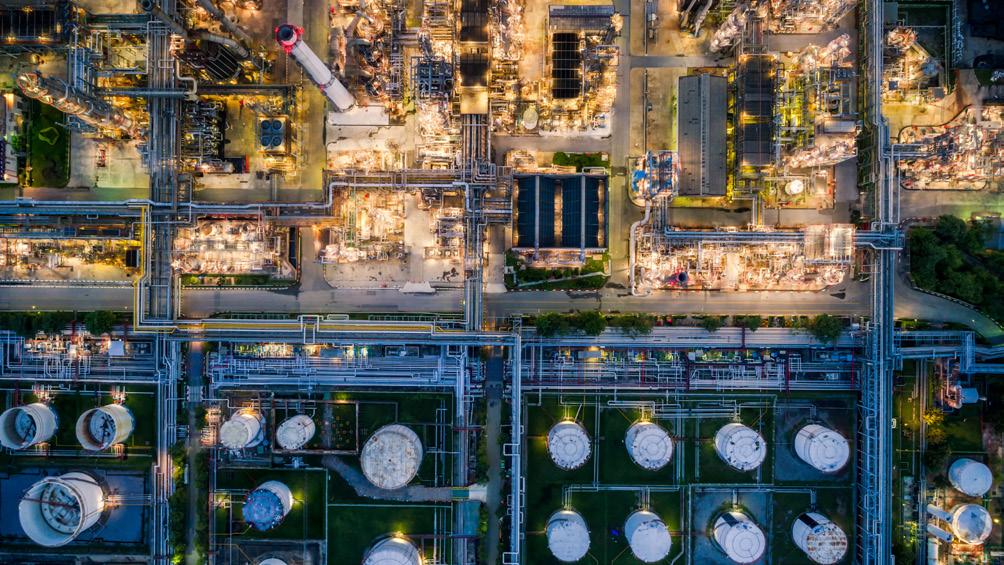
In many countries, demographic shifts are leading to a shrinking workforce, leaving industrial companies with a significantly smaller talent pool to recruit from. Therefore, you need to introduce solutions that enable you to efficiently and securely operate your plants with fewer people. This means embracing AI and increasing digitalisation and automation levels to enable plant operators to make smarter decisions. These solutions require attracting a younger workforce, but Gen Z and Gen Alpha talent are reluctant to work at industrial plants that rely on outdated systems and processes.
This has resulted in an escalating war on talent – a landscape where hiring companies are in stiff competition to recruit a shrinking pool of highly skilled employees. This is a war that can only be won by modernising your control systems to achieve a more attractive and future-ready working environment.
The control system is central to plant operations. It can boost productivity, drive efficiency, guarantee the quality of your product, and provide the reassurance of continuous uptime. Because it is at the core of everything, it must function to the best of its abilities.
Even if your current control system is running at an optimal level, now is the time to plan for transformation. Before performance deteriorates, commercial risk becomes critical, and talent looks elsewhere, it is sensible to embark on a sustainable, cost-effective, and step-wise modernisation programme. Because if you don’t, a competitor will.
ABB took this approach with Austrian energy giant Salzburg AG to upgrade its gas turbine control system at its HKW Mitte plant. Using an in-house code translation process, a system simulator, and a virtual gas turbine model, the team was able to shrink the commissioning time from weeks to days, completing the transformation without any unplanned downtime, delivering maximum efficiency, low maintenance costs, high reliability, and lifecycle enhancement.
Today’s emerging workforce wants to operate within environments that leverage contemporary AI and automation solutions, as implemented at HKW Mitte. New talent, for example, expect to be able to calibrate a field device remotely on a sophisticated control system. In contrast, outdated systems often require field devices to be calibrated on-site, frequently under demanding conditions. This isn’t the kind of environment the best new talent chooses to work in.
Our Head of Modernisation, Volker Jung, has advised customers around the world on real-world impact of modernisation. He often highlights how it can transform talent acquisition and retention, perhaps best illustrated by one of our customers located in Scandinavia near the Arctic Circle. Its plant, despite its extremely remote setting, successfully attracts and retains smart, young talent because it stands out by utilising the latest control system technologies.
It’s important to note that modernising isn’t just about hiring from Gen Z. Many experienced operators and process engineers want to work with AI-powered solutions that help
• Building Canada’s infrastructure for 70 years
• Advocating for the unionized pipeline construction industry with government through labour relations, policy review, pipeline standard codes and more
• Supporting worker safety, recruitment, training and leadership development programs for members
• Fostering a Canadian-based workforce with specialized technical, trade and craft skills for pipeline construction and maintenance
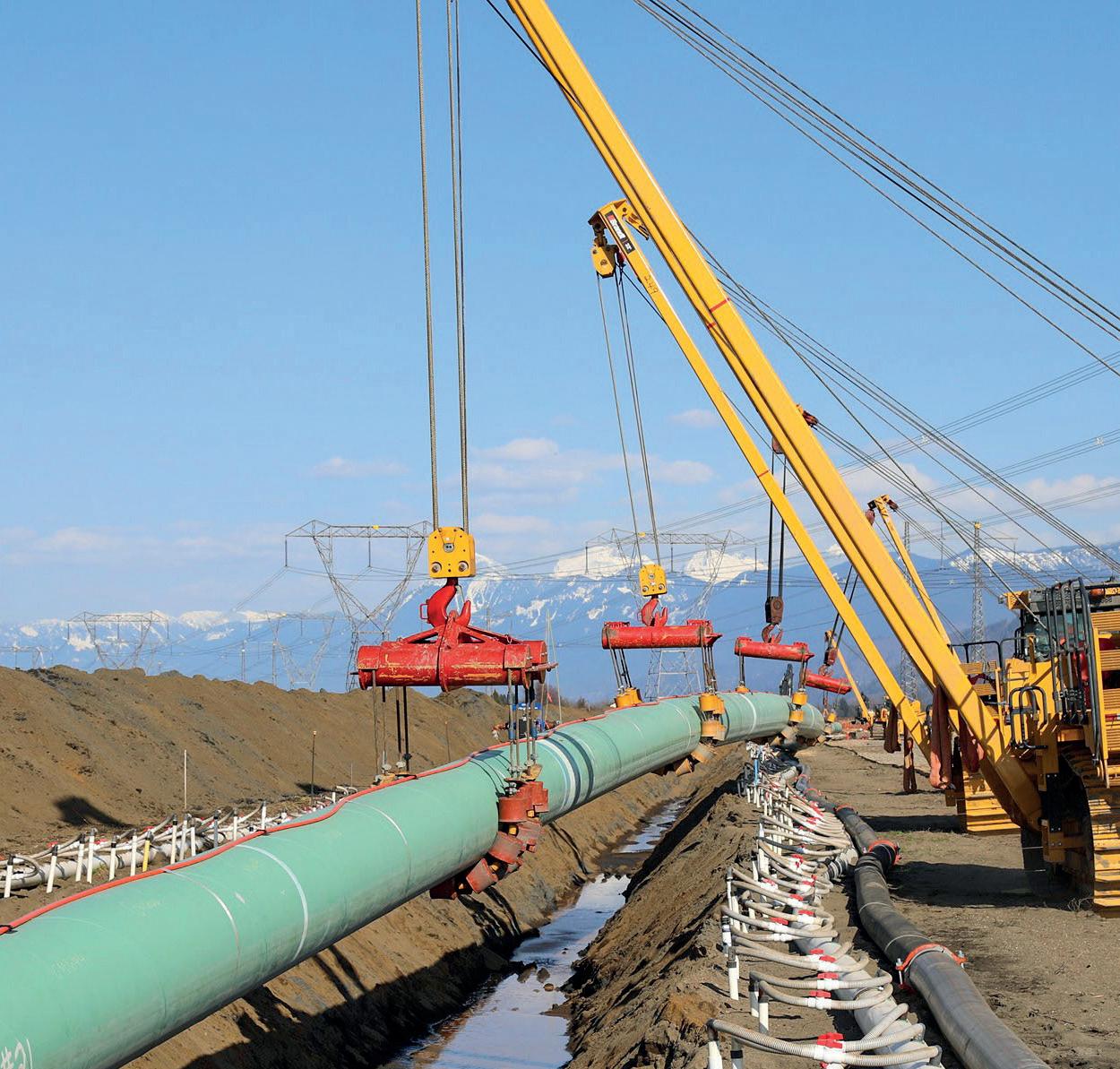
them to drive the plant harder and hit their KPIs. Helping them adapt to new technologies is critical, and a step-wise approach to modernisation supports this.
Building on existing infrastructure enables a smooth knowledge transfer as your experienced engineers and operators begin to retire and your workforce transitions to a new generation. ABB have developed a suite of augmented, machine learning-based algorithms that learn from experienced operators; capturing how they optimise plant output and respond swiftly to abnormal situations. These insights are stored and provided in real time to new hires, allowing them to carry out essential tasks independently, even when senior staff are not on shift, enabling a swift onboarding process to bring them up to speed.
This approach means there is no need to bulldoze everything for a complete system overhaul. By integrating new technologies and solutions layer by layer into your current infrastructure, you adopt a more cost-effective and sustainable path to future readiness. This method ensures minimal disruptions, no production loss, and a robust transfer of knowledge, making it a strategic investment rather than a costly disruption.
Modernisation hinges on trust: trust that your upgrades are business-critical, that the process will avoid significant shutdowns, that robust support will be available for unexpected issues, and that automating your control systems will enhance your organisation’s ability to attract and retain talent.
Trust is paramount. As a company specialising in distributed control systems, ABB speak from a position of authority when discussing modernisation, helping customers understand that failing to do so would risk falling behind their competitors.
This deep level of trust and extensive experience is why they were asked to help evolve to new technologies, including modernising a legacy distributed control system at the Naphtachimie plant. Based near Marseille, the facility produces ethylene, propylene, hydrogen, methane, ethane, and fuel for the French market. This comprehensive modernisation programme significantly improved performance, availability, and reliability, ultimately extending the plant’s operational life by decades and making it both future-ready and future-proofed. Whoever you trust to automate your control systems, today is the day to start your journey. Failing to modernise is a fundamental threat to the long-term viability of your plant. Modernising is a means to optimise operations, reduce costs, support the knowledge transfer between generations and win the war on talent.
1. www.protectedincome.org/wp-content/uploads/2024/01/Whitepaper_Fichtner. pdf
2. https://unece.org/info/publications/pub/401338
3. https://new.abb.com/news/detail/111813/salzburg-based-utility-selects-abb-toimprove-power-plant-operations
4. https://new.abb.com/news/detail/117345/abb-enables-digital-control-systemevolution-project-at-naphtachimie-plant-in-france 5.


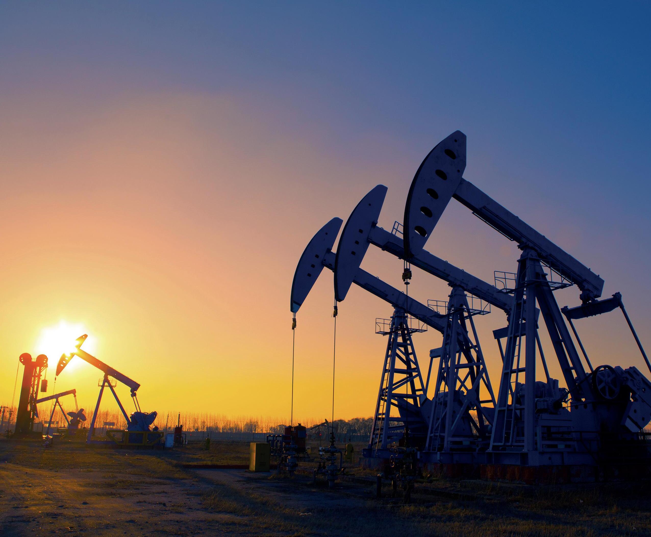
Subscribe online at: www.oilfieldtechnology.com/subscribe