Volume 26 Number 4 - April 2026


Volume 26 Number 4 - April 2026
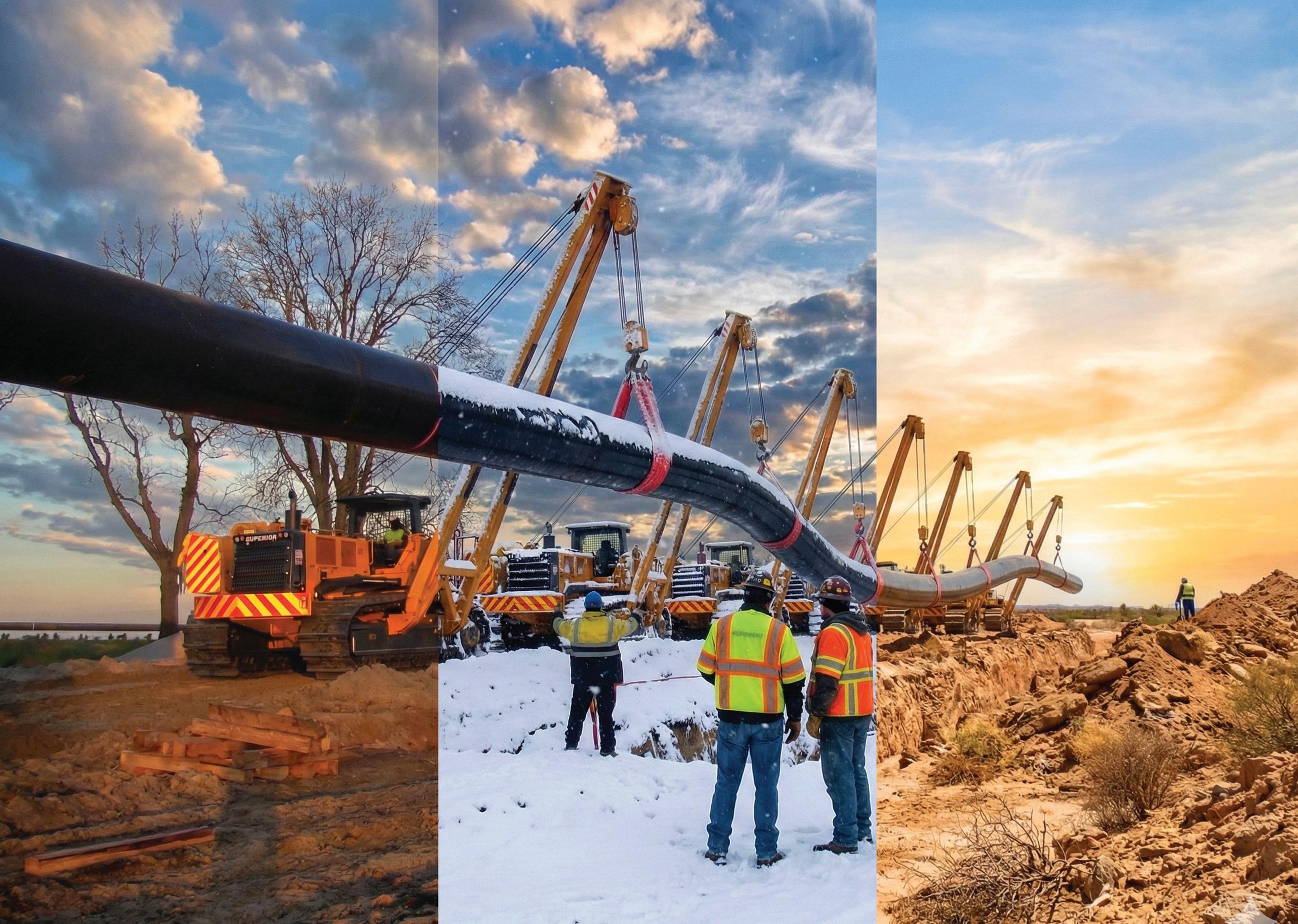
Terrain is unpredictable. Logistics are complex.
But your equipment partner shouldn’t be.
Worldwide Machinery provides a standardized level of excellence in sales and rentals across six continents.
We remove the guesswork from your heavy equipment needs so you can focus on the next mile of pipe.
Whether it’s a mainline spread or a gathering system, we deliver the operational certainty your project demands.

03. Editor's comment
05. Pipeline news
Pipeline news from the Middle East, and contracts for India, and the North
KEYNOTE: HYDROGEN PIPELINES
08. The hydrogen economy: built or broken?
Gordon Cope, Contributing Editor.
13. Invisible infrastructure
Garry Hanmer, Principal Simulation Consultant, Atmos International, UK.
17. Setting a global standard
Robert H. Shelton, CEO and President, and Robert M. Hertzberg, Director, H2C Safety Pipe, Inc.
US PIPELINES
23. Texas runs on the infrastructure we don't see Shelli Myers, Chair, Texas Pipeline Association, USA.
PIPELINE SERVICES
26. Managing distortion
Morgan Sledd and Gilberto Lopez, Stark Solutions, USA.
INTEGRITY AND INSPECTION
31. A new era of crack inspection in gas pipelines
Matthias Hilvert and Thomas Beuker, ROSEN Group.
SYSTEMS AND SOFTWARE
37. Improving pipeline lifespan
Manuel Hernandez, Pipeline Integrity Engineer, NDT Global.
SPOTLIGHT: IPLOCA
41. Celebrating 60 years
Georges Hage, Executive Director, IPLOCA.
OFFSHORE PIPELINES
45. 30 years of flexible pipe integrity management
Ian MacLeod, Technical Director, Wood.
52. A structured approach to offshore pipeline repurposing
Victor Ng, Principal Engineer, and David Baxter, Hydrogen Pipeline Materials Specialist, Kent.
HDD EQUIPMENT
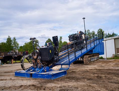
59. Rising to the challenge Richard Levings, Project Manager, American Augers.






MANAGING EDITOR
James Little james.little@worldpipelines.com
ASSISTANT EDITOR
Emilie Grant emilie.grant@worldpipelines.com
SALES DIRECTOR
Rod Hardy rod.hardy@worldpipelines.com
SALES MANAGER
Chris Lethbridge chris.lethbridge@worldpipelines.com
SALES EXECUTIVE
Daniel Farr daniel.farr@worldpipelines.com
PRODUCTION DESIGNER
Siroun Dokmejian siroun.dokmejian@worldpipelines.com
HEAD OF EVENTS
Louise Cameron louise.cameron@worldpipelines.com
EVENTS COORDINATOR
Chloe Lelliott chloe.lelliott@worldpipelines.com
DIGITAL EVENTS COORDINATOR
Merili Jurivete merili.jurivete@palladianpublications.com
DIGITAL CONTENT COORDINATOR
Kristian Ilasko kristian.ilasko@worldpipelines.com
JUNIOR VIDEO ASSISTANT
Amélie Meury-Cashman amelie.meury-cashman@worldpipelines.com
SENIOR WEB DEVELOPER
Ahmed Syed Jafri ahmed.jafri@worldpipelines.com
DIGITAL ADMINISTRATOR
Nicole Harman-Smith nicole.harman-smith@worldpipelines.com
ADMINISTRATION MANAGER
Laura White laura.white@worldpipelines.com
Palladian Publications Ltd, 15 South Street, Farnham, Surrey, GU9 7QU, UK
Tel: +44 (0) 1252 718 999 Website: www.worldpipelines.com Email: enquiries@worldpipelines.com
Annual subscription £60 UK including postage/£75 overseas (postage airmail). Special two year discounted rate: £96 UK including postage/£120 overseas (postage airmail). Claims for non receipt of issues must be made within three months of publication of the issue or they will not be honoured without charge. Applicable only to USA & Canada: World Pipelines (ISSN No: 1472-7390, USPS No: 020-988) is published monthly by Palladian Publications Ltd, GBR and distributed in the USA by Asendia USA, 701C Ashland Avenue, Folcroft, PA 19032. Periodicals postage paid at Philadelphia, PA & additional mailing offices. POSTMASTER: send address changes to World Pipelines, 701C Ashland Avenue, Folcroft, PA 19032.

SENIOR EDITOR Elizabeth Corner elizabeth.corner@worldpipelines.com
Rystad Energy estimates a US$25 billion repair bill for Gulf energy infrastructure, amid largescale military conflict in the region. “War in the Middle East has triggered severe global supply disruptions in oil and gas, with reported damage and shutdowns affecting LNG trains, refineries, fuel terminals and critical gas-to-liquids facilities across the region.”1 Iranian media reports that a gas pressure station and a pipeline near the Khorramshahr power plant were damaged by projectiles. Iran has targeted energy infrastructure in Gulf Arab states, including the Ras Tanura refinery in Saudi Arabia and the Fujairah oil terminal in the UAE. Traffic through the Strait of Hormuz – through which around 20% of the world’s oil flows – has been significantly curtailed. Even infrastructure designed to bypass the Strait, such as the Abu Dhabi Crude Oil Pipeline (ADCOP), is not immune to the wider risks posed by regional instability. Damage is widespread, with reports of up to 40 energy assets damaged across nine countries, causing massive revenue losses and global price spikes.
And yet, within this disruption, there are important contrasts. Saudi Aramco’s rapid restart at Ras Tanura (11 days after a 2 March drone attack caused a precautionary shutdown) highlights the often-overlooked advantage of domestic EPC capability: where local expertise and resources are readily available, recovery can be accelerated significantly. In contrast, projects dependent on constrained global supply chains or affected by sanctions face a much longer road to restoration. From LNG trains in Qatar, to refinery units in Bahrain, those countries with the ability to execute repairs (with the requisite access to specialist equipment, engineering capacity, and supply chains) win out. In some cases, particularly where specialist turbomachinery is required, lead times of several years mean that restoration timelines will extend far beyond initial repair efforts. This has important implications for pipeline and midstream infrastructure. While some assets across the region may return to service relatively quickly, others will remain offline for prolonged periods.
The immediate impacts of disruption in the Middle East are damaged assets, delayed production, and mounting repair costs. However, for the pipeline and wider energy infrastructure sector, longer-term consequences are likely to hang on less visible pressures.
Insurance and risk premiums are already emerging as a key constraint. Rising war-risk and marine insurance costs can quickly affect the viability of both shipping and project execution, hurting supply chains and inflating EPC pricing. At the same time, uncertainty around transit through the Strait of Hormuz is not only a concern for oil and LNG flows, but also for the movement of pipe, equipment, and specialist components.
Regional instability can delay mobilisation of skilled personnel, particularly for complex engineering work, slowing both repair efforts and ongoing developments.
The materials picture, for now, remains relatively stable. Signal Ocean notes that Gulf disruption has yet to significantly impact global steel flows, although trade is beginning to shift away from the region.² Markets have so far absorbed disruption through inventories and delayed shipments. But steel production accounts for around 7 - 8% of global energy demand, so sustained increases in energy prices could squeeze margins and trigger output cuts in highercost regions such as Europe.
Overlaying all of this is the influence of energy markets: sustained price volatility hits consumers, and impacts directly on construction and operating costs, tightening pressure on project economics and timelines across the board.
1. https://www.rystadenergy.com/news/middle-east-conflict-rebuild-energy-cost
2. https://www.thesignalgroup.com/
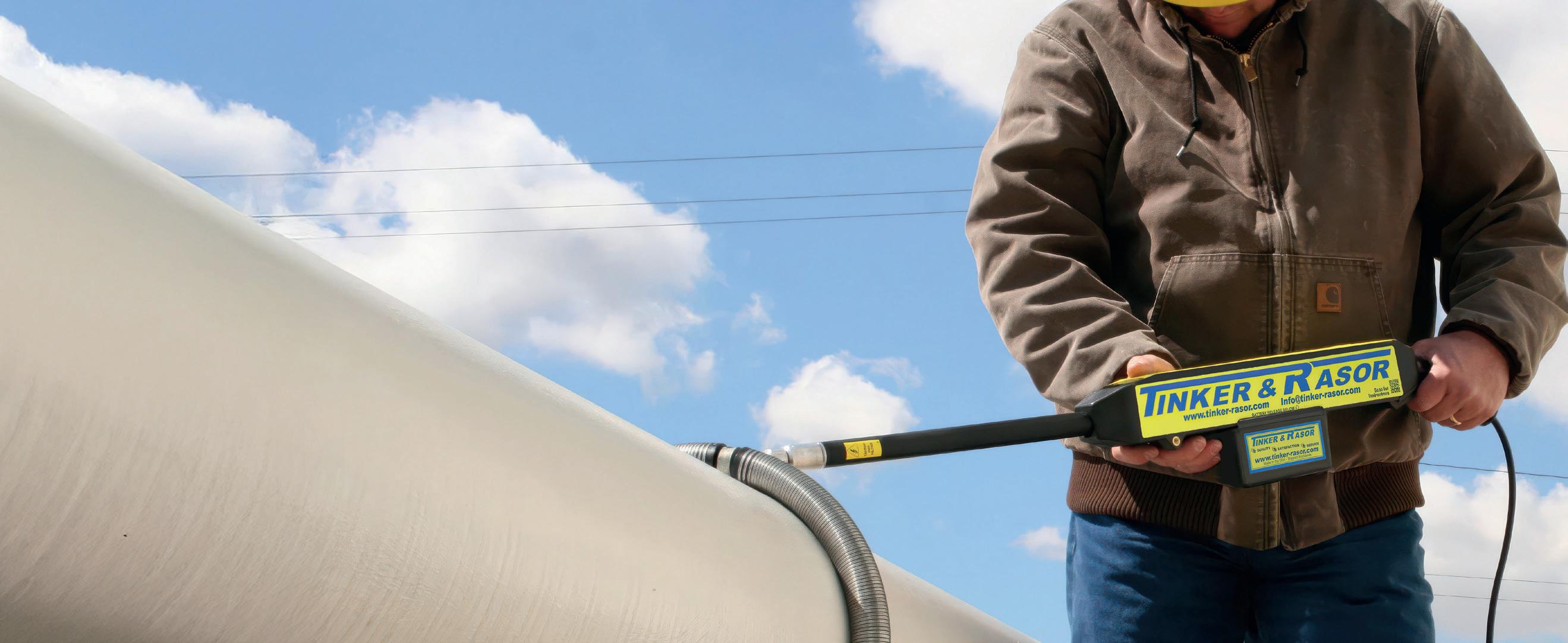
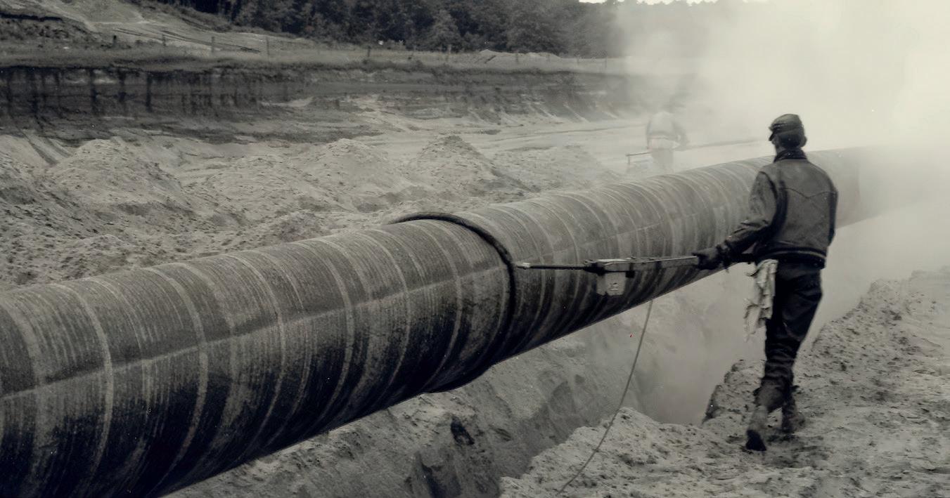
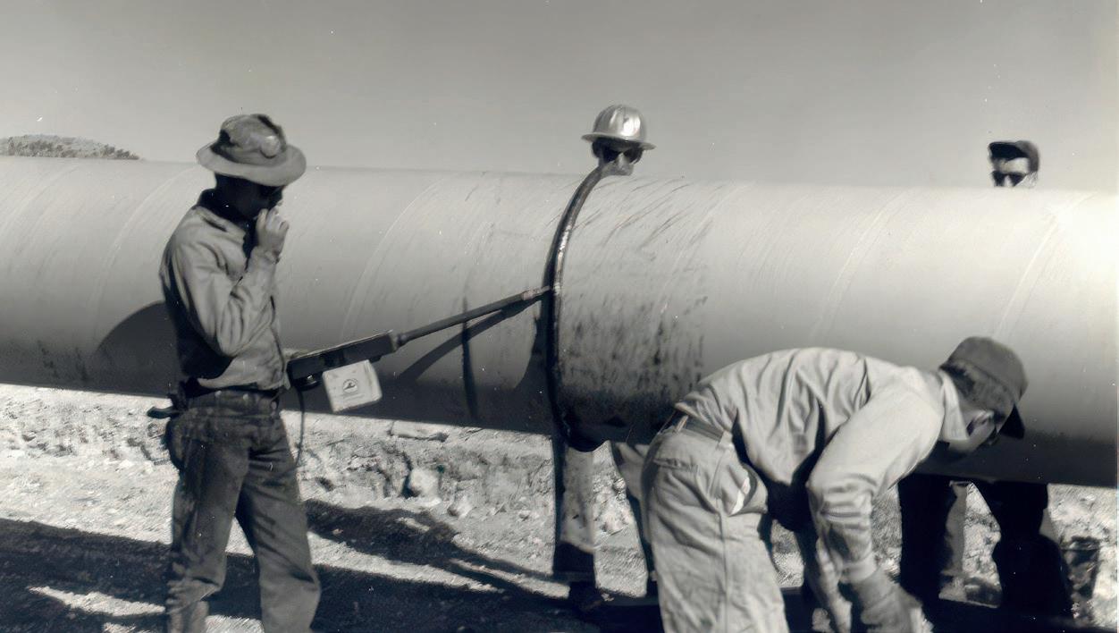
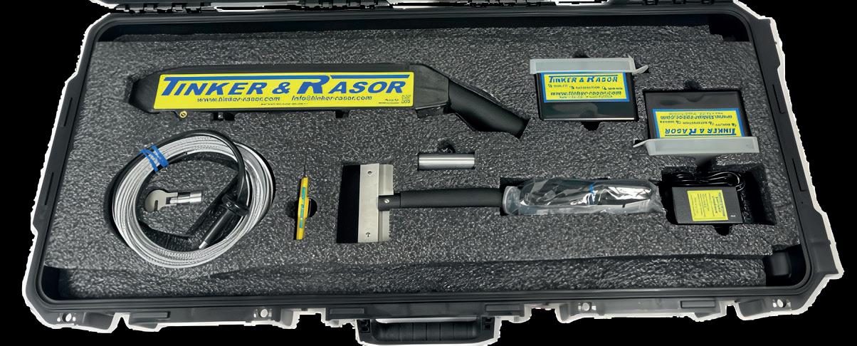
Since 1948, Tinker & Rasor has been a trusted name in holiday detection, relied upon by pipeline professionals worldwide. For over 76 years, our holiday detectors have set the benchmark for performance and reliability, ensuring the integrity of protective coatings by detecting coating flaws with precision. With a legacy of innovation and toughness, Tinker & Rasor continues to lead the industry, delivering cutting-edge solutions to safeguard pipeline coatings and maintain quality standards across the globe.
Gulf energy infrastructure: repair and restoration costs to reach US$25 billion
According to Rystad Energy’s estimates, Middle East energy infrastructure repair and restoration costs to date could reach at least US$25 billion, based on an initial assessment of impacted facilities, and are expected to rise further. Spending is likely to be driven primarily by engineering and construction, followed by equipment and materials.
In assessing repair costs and full restoration timelines across severity tiers, one clear outlier emerges in Qatar’s Ras Laffan Industrial City, where the destruction of LNG trains S4 and S6 has triggered force majeure and a 17% capacity reduction, equivalent to about 12.8 million tpy. However, capital alone will not be sufficient to restore the facility, with a full recovery taking up to five years. This is because the large-frame gas turbines required to power LNG main refrigeration compressors are supplied by only three original equipment manufacturers (OEM) globally, all of which entered 2026 with production backlogs of around two to four years, driven by demand from data centre electrification and coal plant retirements.
Audun Martinsen, Head of Supply Chain Research at Rystad Energy, notes: “The Gulf region’s recovery will be defined less by financial capital and more by structural constraints. While some assets may be restored within months, others could remain offline for years. Beyond the status of the Strait of Hormuz, every day of damaged or shut-in infrastructure pushes pre-war production capacity further out of reach. Iran’s South Pars offshore field and Qatar’s Ras Laffan facility stand out as particularly concerning cases. The scale of damage and long lead times for critical equipment could result in slow recovery at Ras Laffan, while Iran’s legal exclusion from Western supply chains means it will have to rely on Chinese and domestic contractors, which is a technically feasible approach that could be slower and more expensive. Urgent repairs will have to take precedence in place of planned expansion.”
Looking beyond Qatar, neighbouring Bahrain represents another distinct disruption scenario. The BAPCO Sitra Refinery was struck twice, causing confirmed damage to two crude distillation units (CDU) and a tank farm, with force majeure
declared across group operations. Here, the constraint is not equipment shortages or sanctions, but the timing of the damage relative to the asset’s investment cycle. The facility had just reached mechanical completion under its US$7 billion modernisation programme in December last year, with engineering, procurement and construction (EPC) contractors still onsite finalising ramp-up obligations when the attacks occurred. The destruction of a newly commissioned CDU block just months after first production has eliminated novel processing capacity, delaying the revenue intended to support the recent investment. Restoring the units will likely require international contractors to be re-mobilised at conflict-inflated costs and under uncertain war-risk insurance, as the damaged assets had only recently come online.
There were also moderate-to-minor disruptions in other countries, including the UAE, Kuwait, Iraq and Saudi Arabia. Across all impacted facilities, the factor that most consistently shapes recovery trajectories is the density and proximity of the domestic EPC ecosystem surrounding each asset – an often-underestimated variable in conventional damage assessments. Saudi Aramco’s rapid restart at Ras Tanura, where maintenance teams were already onsite for a planned turnaround when debris fell inside the perimeter, provides the clearest example of the advantages enabled by deep domestic capability.
The speed of recovery in the region will depend on execution capacity and capital deployment timing, as repair spending ramps up. Operators are likely to prioritise restoring existing fields instead of new developments, creating demand for EPC contractors and OEMs, especially those with regional experience and existing agreements with national oil companies. Near-term work will most likely focus on inspection, engineering and site preparation, followed by equipment replacement and construction as procurement constraints ease. In Iran, continued sanctions would limit access to Western contractors and technology, leaving domestic and East Asian players to capture most recovery-related activity.
Reuters has reported that Iraq is working to revamp a disused pipeline that would allow oil to be pumped directly to Turkey’s Ceyhan port without passing through the Kurdistan region, Iraqi Oil Minister, Hayan Abdel-Ghani, has said in a video statement. Iraq will complete inspection of a 100 km (62 mile) section of the pipeline ‘within a week from now’ to enable direct exports from Kirkuk, he added.
The reopening of the Kirkuk-Ceyhan pipeline, which has been shut for more than a decade, would provide an alternative route to a pipeline from the Kurdistan region. Exports via the 960 km pipeline, which once handled about 0.5% of global supply, were halted in 2014 after repeated attacks by Islamic State militants.
The oil ministry had previously asked the Kurdistan Regional Government to allow it to use the Kurdistan pipeline as an
alternative route for crude flows disrupted by the Iran conflict. But it later said the KRG had set arbitrary conditions for the pipeline’s use.
In response, Iraq’s Kurdish authorities rejected the accusation they were refusing to allow crude exports through the pipeline and said Baghdad had failed to address security and economic challenges facing the region’s oil sector.
Oil production from Iraq’s main southern oilfields, where most of its crude is produced and exported, plunged 70% to just 1.3 million bpd, sources told Reuters in early March, as the Iran conflict effectively shut off the vital Strait of Hormuz.
Iraq’s Oil Ministry sent a letter in early March to the KRG in northern Iraq seeking permission to pump at least 100 000 bpd of crude from Kirkuk oilfields through the pipeline network to Türkiye’s Ceyhan energy hub, according to reports.
20 - 24 April 2026
PLCAC convention
Maui, Hawaii
https://pipeline.ca/
27 - 30 April 2026
Lamprell has been appointed by Oil & Natural Gas Corp. (ONGC) to deliver the pipeline replacement project PRP-IX in India.
Pipeline Technology Conference (PTC)
Berlin, Germany
https://www.pipeline-conference.com/
4 - 7 May 2026
Offshore Technology Conference (OTC)
Houston, USA
https://2026.otcnet.org
2 - 3 June 2026
Gas, LNG & The Future of Energy 2026
London, UK
https://www.woodmac.com/events/gas-lngfuture-energy/
9 - 11 June 2026
Global Energy Show 2026
Calgary, Canada
https://www.globalenergyshow.com/
14 - 17 September 2026
Gastech 2026
Bangkok, Thailand
https://www.gastechevent.com
15 - 16 September 2026
Subsea Pipeline Technology Congress (SPT 2026)
London, UK
https://sptcongress.com/
22 - 24 September 2026
International Pipeline Conference and Expo 2026
Calgary, Canada
https://www.ipceyyc.com/
2 - 5 November 2026
ADIPEC 2026
Abu Dhabi, UAE
https://www.adipec.com/
This very large contract covers the replacement and laying of approximately 285 km of subsea pipelines of various sizes across ONGC’s Western offshore fields, Mumbai High, Neelam and Heera, Bassein and Satellite fields, together with associated topside modification works across multiple offshore platforms.
This award highlights Lamprell’s growing strength in the offshore market and its ability to provide integrated EPC, transportation, and installation solutions for major energy clients.
Ian Prescott, CEO of Lamprell, commented: “We are honoured by the trust ONGC has placed in Lamprell through this award. PRP-IX is a technically demanding
North Sea contract for Kelton
A new six-figure, multi-year contract contract will see Kelton’s expert consultants audit a significant North Sea pipeline system on behalf of a major engineering client, which acts as an operating partner for the system, its various pipelines, and the terminal point in the north of Scotland.
Kelton, which celebrates its 35th anniversary this year, has long held a reputation as a go-to provider of specialist consultancy services and has a long history of supporting the subject of this new contract and the North Sea region, dating back to the early 1990s.
Through receipt of this new contract, Kelton will maintain its 30+ year relationship with the North Sea. The contract marks the third stint in which Kelton has supported the client and the system, following previous contracts from the 1990s to early 2010s and again from 2023 to 2025, when Kelton was once again recommended for its reputation and history.
Through the contract, Kelton will act as the third-party independent authority for the provision of calibration witnessing, measurement system and mismeasurement audits for the pipeline system.
While a significant portion of the measurement audits will be conducted at the offshore pipeline entrance, a series of onshore terminal audits will also be conducted to maintain the same high standard of measurement across the system.
project that builds on our in-house engineering, project management, and marine capabilities. We are well-positioned to deliver a high-quality project that supports ONGC’s offshore infrastructure programme and India’s broader energy objectives.”
Lamprell is a provider of EPCI contracting services to the international energy sector, via its oil and gas, and offshore wind, business units. The Group is recognised for delivering complex onshore infrastructure projects, offshore process modules, jackets and platforms, as well as fabricating and refurbishing jack-up rigs and liftboats. Lamprell employs more than 6000 people across its operations, with primary facilities in Hamriyah and Jebel Ali in the UAE, as well as business support offices in India and Saudi Arabia.
• New DNV recommended practice supports offshore hydrogen pipelines development
• Trump’s Transportation Department to invest nearly US$100 million in modernising ageing pipeline infrastructure
• World Pipelines interviews Ditch Witch at CONEXPOCON/AGG 2026
• First major hydrogen plant connected to Dutch hydrogen pipeline
• Triple-digit oil: temporary spike or a new market reality? Rystad Energy reports
Follow us on LinkedIn to read more linkedin.com/showcase/worldpipelines


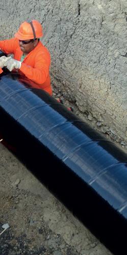
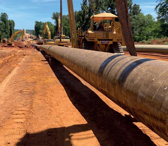
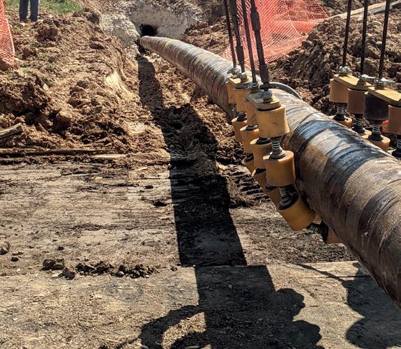
PROTECTIVE OUTERWRAPS
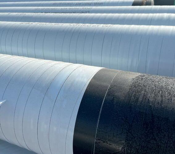
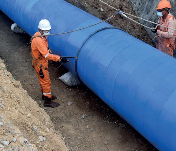
VISCOELASTIC COATINGS
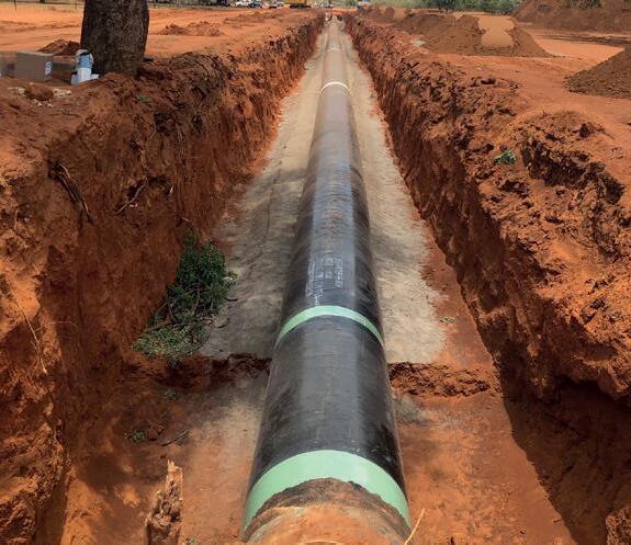
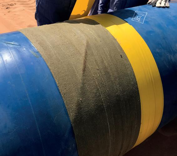
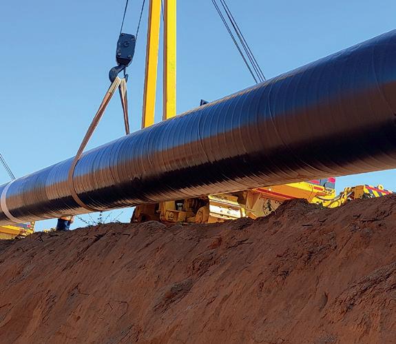
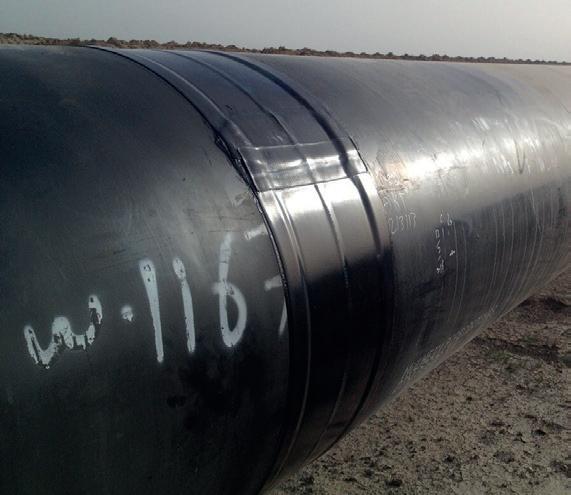
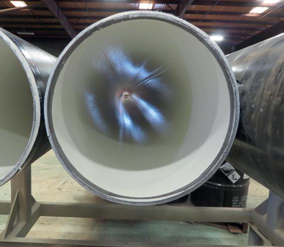
INTERNAL PIPE LININGS
The hydrogen economy is starting to look more like a lead balloon, than an economy soaring to new heights, writes Gordon Cope, Contributing Editor.
The proposed hydrogen economy is seen as a panacea to many woes. When burned in vehicles, utilities, or homes, the colourless, odourless gas provides energy and heat while emitting nothing but harmless water vapour. The security-of-supply worries due to nefarious energy suppliers is avoided by the fact that hydrogen can be produced anywhere. Finally, hydrogen production using renewablesbased electrolysis dramatically reduces emissions from the manufacture of fertilizers, steel and a host of other products.
In order to transform the energy landscape, however, the hydrogen economy needs to establish three industrial-scale

components; manufacturing plants, dedicated pipelines, and consumers.
Production
China currently has over 200 000 tpy of hydrogen plant capacity currently in operation, including the Daye Green Power plant in Hubei province, the Songyuan plant in Northeast China, and several facilities in Inner Mongolia. Europe is also strongly pro-hydrogen; in addition to €13 billion that has already been earmarked for improving hydrogen technology, production, and demand, the EC
announced plans in December 2025, to distribute up to €1.2 trillion to beef up electricity grids through 2040, including €240 billion for the production, transportation, and consumption of hydrogen. Iberdrola’s plant in Spain is producing 500 000 tpy, and major plants in Germany, France, and Sweden are expected to add over 200 000 tpy of capacity in 2026.
In the US, Air Products is building the Louisiana Clean Energy Complex in Burnside, Louisiana, US. The US$4.5 billion facility will produce 750 million ft3/d of blue hydrogen which will then be converted into 600 000 tpy of blue ammonia. When it enters production in 2029, the plant will capture and sequester approximately 5 million tpy of carbon dioxide.
RIC, based in Spain, is now in the planning and permitting stage for its 120 MW electrolyser plant on the Cadiz Ranch, located in the Mojave Desert 300 km east of Los Angeles, US. The facility will use solar power to produce up to 50 short tpd of green hydrogen.
In Canada, Air Products is building a hydrogen energy complex in the Fort Saskatchewan industrial region near Edmonton, Alberta. The facility will create 800 000 tpy of blue hydrogen, using auto thermal reforming (ATR). The budget has increased from US$1.3 billion to US$3.3 billion, and the timeline for completion pushed back to 2027. Once commissioned, Air Products will use its 55 km pipeline network to deliver blue hydrogen to Shell’s diesel refinery, as well as to third parties in the industrial region.
Japan is deficient in traditional fossil fuels, and views hydrogen as a next-generation energy source that will decrease greenhouse gas (GHG) emissions and augment security; the government has announced plans to boost hydrogen supplies from 4 million tpy to 12 million tpy by 2040. The country’s first green hydrogen plant entered service in late 2025 when Green Hydrogen Park Hakushu in Hokuto City went online. The US$122 million plant produces 2200 tpy for use at Suntory’s nearby whisky-making facilities. Mitsubishi Heavy Industry, Toyota, Hokkaido Electric Power, and the Japan Atomic Energy Agency all have plans to build green hydrogen plants.
China has a long-term goal of building up to 6600 km of dedicated hydrogen pipelines to move the gas from solar-rich western desert regions to industrial consumers in the east. Currently, the 1000 km Kangbao-Caofeidian Pipeline Network and the 400 km Inner Mongolia-Beijing Pipeline are under construction.
In the EU, Dutch gas network operator Gasunie is building a 1200 km hydrogen pipeline network to serve both domestic customers and export to neighbouring countries. The first section, a 32 km stretch in the Port of Rotterdam, was completed in 2025. Further work includes the Delta Rhine Corridor (DRC), which will run from Rotterdam to Germany’s Ruhr and Rhineland industrial regions. The company expects the system to be in operation by 2033.
Germany’s hydrogen production and distribution network has been estimated to cost US$21.6 billion and extend for 9700 km. In late 2025, Germany’s gas transmission association FNB Gas announced that the first 525 km of the grid had been
built from the Baltic Sea to Saxony-Anhalt, largely using existing natural gas lines. They estimated that the entire system would be completed by 2032.
The US already has approximately 1600 km of dedicated hydrogen pipelines in the US Gulf Coast (USGC). The largest operator is Air Products’ Gulf Coast network, which stretches almost 1000 km from Galveston Bay, Texas, to New Orleans, and serves over four dozen major industrial customers.
Southern California Gas (SoCalGas) has entered into the planning, development and regulatory approval stages for Angeles Link, a dedicated, green hydrogen pipeline system that could deliver enough hydrogen to displace the equivalent of 3 million gal./d of diesel fuel. The pipeline would likely originate in the wind and solar-rich desert east of Los Angeles, and terminate at the port of Los Angeles.
Several North African countries have plans to leverage existing gas pipelines to Europe. Tunisia is looking to export as much as 8 million tpy of hydrogen through the Trans-Med gas pipeline that links Tunisia to Italy by 2050. In July 2025, Algeria’s Ministry of Energy, Mines, and Renewable Energies announced plans to spend up to US$25 billion developing a national green hydrogen network and exporting up to 1 million tpy to Europe by 2040.
In December 2025, Australia’s APA Group concluded a feasibility study to investigate whether a section of its Parmelia gas pipeline near Perth could be converted to hydrogen. The study concluded that the 43 km line could be converted to 100% hydrogen service in a technically feasible, safe and efficient manner. Plans are now underway to establish commerciality.
In January 2026, Oman announced that it is building a 400 km network of dedicated hydrogen pipelines. The Middle East country has plans to produce 1 million tpy of renewable hydrogen by 2030; the network will gather the clean energy for distribution to domestic users and for export to Europe.
In China, state-owned companies have committed to buying green hydrogen, including refinery giant Sinopec, methanol and ammonia manufacturer Chine Energy Engineering Group (CEEC), and electricity utility company China Huaneng.
In the EU, TotalEnergies is using green hydrogen to lower its carbon footprint at refineries, Iberostar Group will use it to heat its hotels in Spain, and electric utility Engie to power industry and transportation.
Japan has a wide range of companies that have announced plans to use green hydrogen. Nippon Steel, JFE Steel, and Kobe Steel will use it in blast furnaces. Hokkaido Electric Power Company (Hokuden) is aiming for 100% green ammonia fired power generation. Toyota and Honda are developing fuel cell vehicles (FCVs) that will run on hydrogen fuel.
There has been a recent spate of cancelled projects; the Hydrogen Council, an advocacy group composed of international corporations, notes that since mid-2024, 52 lowcarbon and renewable hydrogen projects in the EU have been








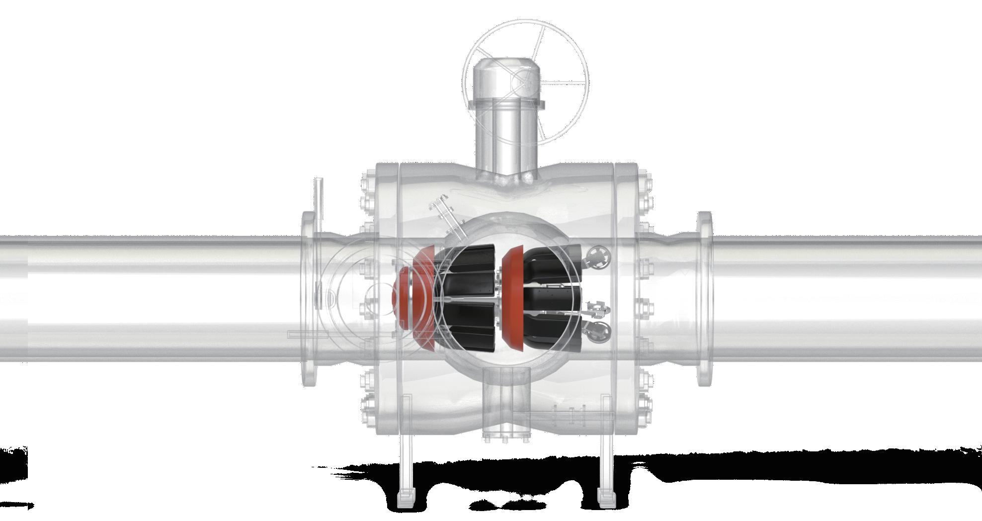
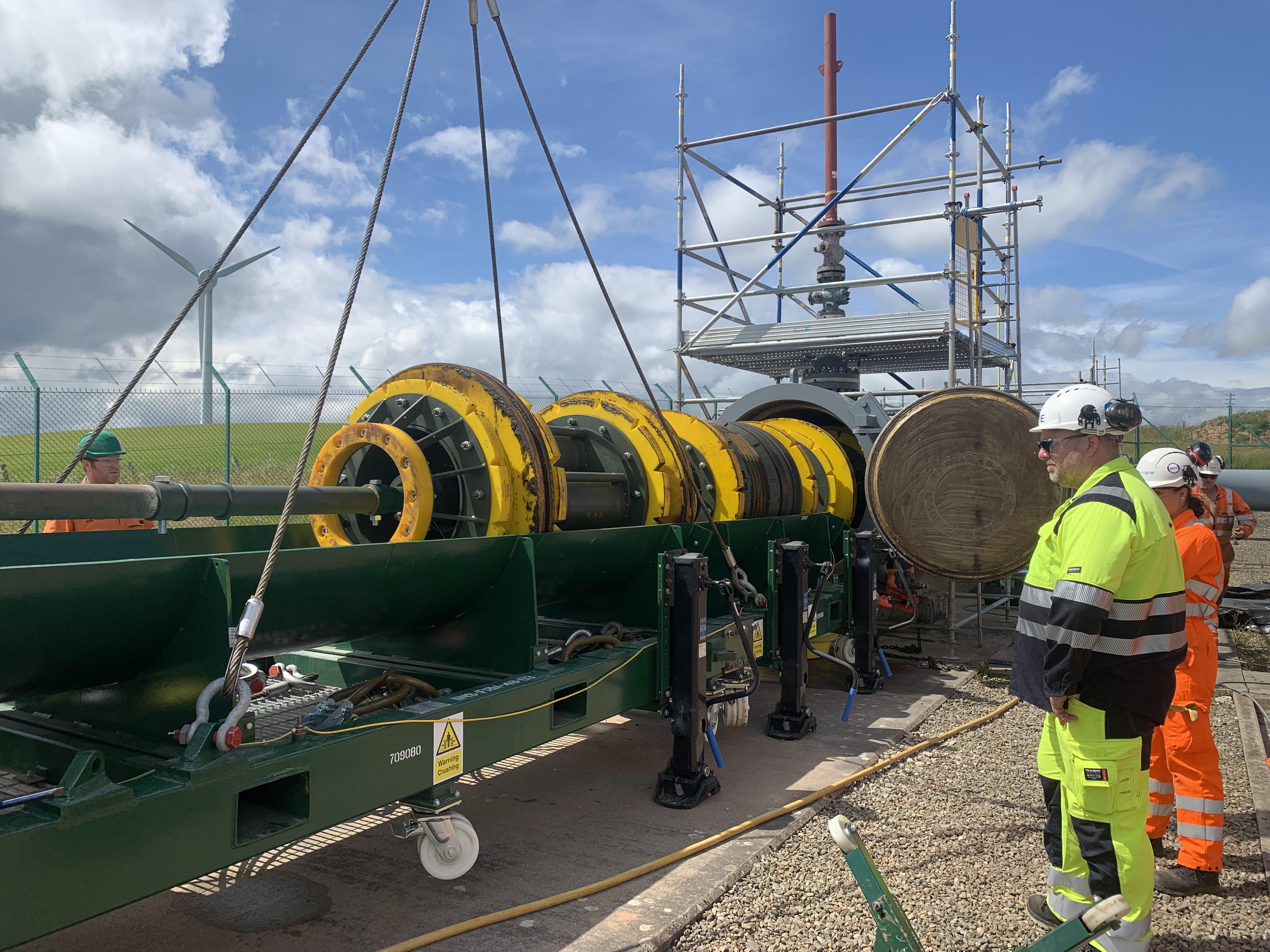
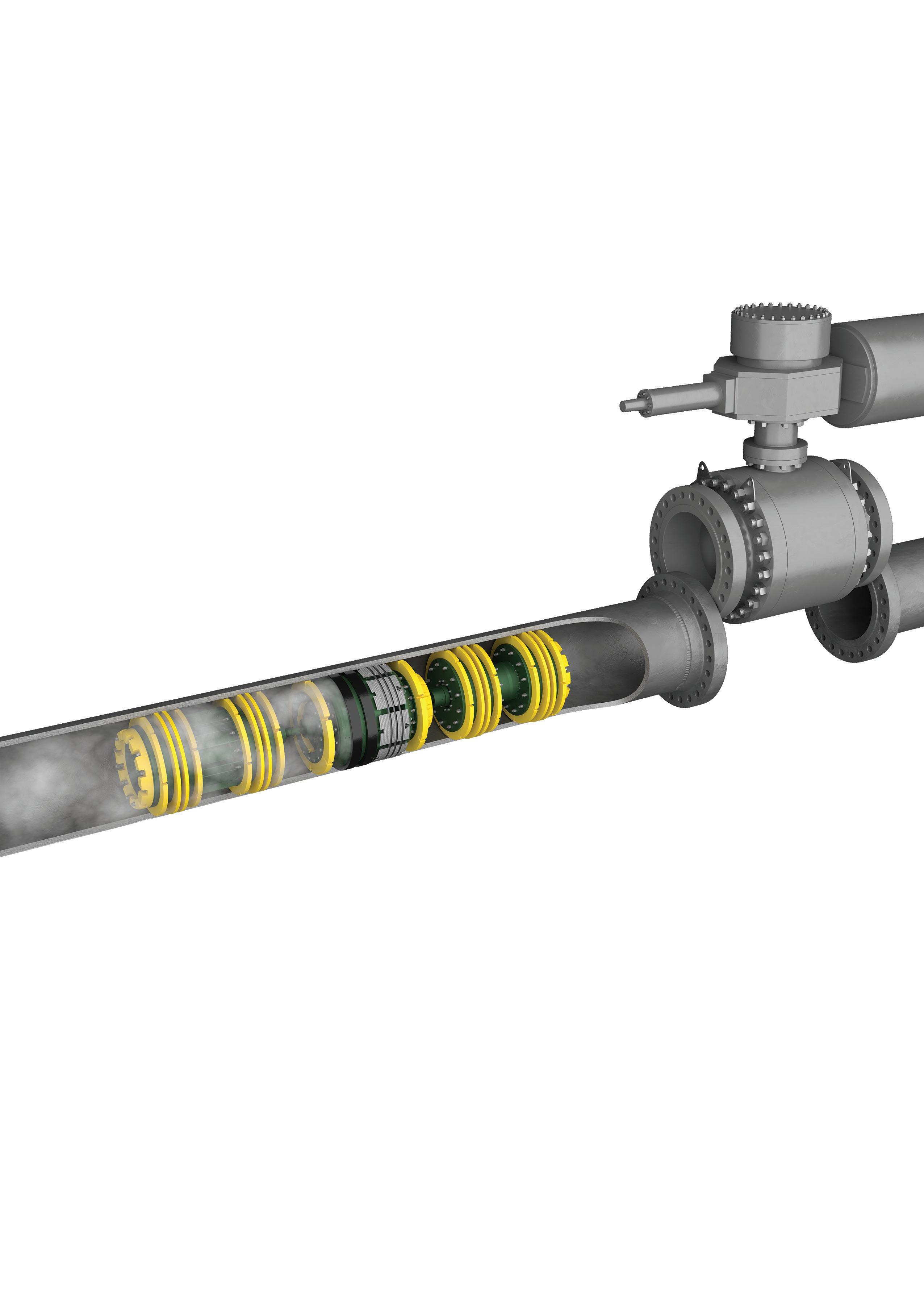
The Remote Tecno Plug® provides fail-safe double block and monitored isolation of pressurised pipelines while the system remains live and at operating pressure.
size range: 10” - 56”
max pressure: 200bar / 2900psi






axed. These include all plans by Norway’s renewable energy company Statkraft, as well as BP’s decision not to proceed with a hydrogen plant in Teesside.
In the US, Air Products has cancelled three low-carbon projects, including a 12 000 tpy green hydrogen plant in upstate New York. It is also in negotiations to sell its stake in the Louisiana Clean Energy Complex to fertilizer giant Yara. The company cited uncertainty in the Trump administration’s approach to renewable energy.
Affordability, however, is the primary reason for the spate of backtracking. In spite of intensive research and innovation, green hydrogen has remained expensive. In order to compete with the dirty grey sort, it has to reduce from current levels of US$8 - 10/kg to approximately US$4/kg. Forecasts for when this will happen remain stubbornly stuck in ‘next decade’ territory. Corporations that want to reduce their carbon footprint (either by goodwill or laws), are reluctant to commit to expensive inputs when competitors face no such onus.
Other factors lurk, many of which pertain to pipelines. Midstream companies make their money by establishing tolls per unit shipped; for crude, refined fuels and natural gas, regulatory agencies ensure that users do not find themselves paying excessive sums, while pipeline companies retain reasonable returns on investments.
Nobody really knows with any assurance how much it will cost to ship 1 kg of hydrogen, however. There are several reasons. The debate over using existing pipeline vs bespoke networks, for instance, is barely beginning. Companies with natural gas networks confidently claim that their infrastructure can easily handle hydrogen. Professional engineering groups differ in opinion. The American Society of Mechanical Engineers (ASME) notes that the existing code for natural gas pipelines is less stringent than the hydrogen pipeline code, implying that gas pipelines don’t automatically meet hydrogen safety requirements.
The main point of contention is that hydrogen is known to cause embrittlement in regular steel, and existing hydrogen pipeline systems (such as those in Texas), must ensure that not only pipe walls, but valves, fittings and bolts, meet tailored specs. Which argument prevails has repercussions; requiring companies to build new networks adds billions to the bottom line. A recent audit commissioned by the Dutch government noted that pipeline transmission fees could rise from an estimated €0.50/kg to over €4/kg by 2033. Ignoring safety warnings, on the other hand, increases the potential for embarrassing explosions.
Secondly, there are few agencies specifically tasked with regulating hydrogen pipelines. In the US, the states of Texas and North Dakota have passed legislation allowing intra-state networks, but the Federal Energy Regulatory Commission (FERC), which is in charge of interstate gas and liquid pipelines, has no specific mandate for hydrogen pipelines. Without regulatory officials willing and able to examine and approve systems, proponents face confusion, uncertainty and delays.
Thirdly, there is no iron-clad consensus on where hydrogen pipelines should go. Currently, plans to build
networks involve starting and end-points based upon traditional energy corridors; from a port (where, say, green hydrogen arrives by ship), to an industrial centre full of steel mills and electricity plants. Making ROW decisions on current assumptions that may prove incorrect in a decade risks stranding pricey assets.
Those who are optimistic about the hydrogen network see the current woes as challenges, not deal-killers. The lack of demand is spurring analysts to pair fuels with the most likely users based upon economics. The ‘Swiss Army Knife’ model in which engineers find a use for hydrogen in every conceivable sector, including aviation, land transportation, and utilities, is yielding way to the ‘Hydrogen Ladder’, where less-costly renewables such as wind and solar generated-electricity can be easily incorporated into cars, shipping and public transportation. Green hydrogen can then meet specific usages that generate big environmental wins, such as fertilizer, hydro-cracking, and desulfurisation.
Pipeline operators are looking at resolving the controversy over embrittlement by mixing hydrogen with natural gas in their networks. Engineering trials have shown that blends of up to 5% hydrogen do not cause steel embrittlement; Atlanta-based Southern Company, which serves over 4 million customers in the US, is experimenting with gas/hydrogen blends in its infrastructure.
In the longer term, white hydrogen also has the potential to drastically reduce costs. Natural deposits occur where groundwater interacts with iron-rich basalt deposits to produce hydrogen. The element then accumulates in reservoirs much like natural gas. Recently, researchers in Alsace Lorraine have identified as much as 92 million t in abandoned coal mines. Mining Giant Fortescue has invested in HyTerra, which is drilling in Kansas. Mantle8, an explorer in Europe backed by billionaire Bill Gates, estimates that it could produce hydrogen for as little as US$0.80/kg. Bespoke pipelines could then deliver it to fertilizer plants, steel mills, and refineries.
Even further down the road, cheap hydrogen could be produced from agricultural waste. In China, scientists have made a breakthrough that may introduce an entirely new – and inexpensive – way to make pure hydrogen. Researchers at the China Agricultural University took sugar derived from cellulose and electro-iodised it to form ‘formate’ (an anion of formic acid), that drastically reduces the amount of energy needed. In essence, they say, a module attached to a refinery could produce green hydrogen from wheat stalks for as little as US$1.50/kg.
In conclusion, the rollout of the hydrogen economy is expected to proceed in a patchwork fashion. The Trump administration has pulled the rug out from under many North American projects, but enthusiasm (and funding) remains in other major jurisdictions, including China, the EU, and Japan. Regardless, pipeline companies will play an integral part in those projects that succeed, facing significant risks as well as substantial rewards.

Garry Hanmer, Principal Simulation Consultant, Atmos International, UK, suggests how data can fill the gaps in hydrogen-ready gas networks.
Gas distribution networks are entering a period of profound change. As hydrogen and biomethane are introduced to support decarbonisation targets, networks originally designed for a single, predictable fuel are being asked to operate under far more dynamic conditions. Pressure behaviour is no longer uniform, gas quality varies across time and location and traditional assumptions around billing and control are no longer valid.
Physical upgrades like injection facilities and material compatibility are only half of the equation. In modern pipeline operations, software, data, and network models have evolved from support tools into critical infrastructure. The ability to simulate complex thermodynamics and maintain a real-time digital record is now as essential to operational safety as the integrity of the steel pipeline itself. In many cases, they are enabling the transition where physical instrumentation alone cannot.
This article explores how advanced data-driven systems are helping operators manage the operational and commercial realities of hydrogen-ready gas networks. Instead of focusing on hardware expansion, it examines how digital modelling and estimation techniques are filling visibility gaps, improving decision-making and supporting fair energy delivery in increasingly complex systems.
Traditional gas networks were built around relative consistency. Natural gas composition varies slightly by source, but its physical behaviour is stable enough that networks can be operated using averaged values and predefined operating envelopes. Pressure control, capacity planning, and billing methodologies all evolved within this context. Blending hydrogen and biomethane into the natural gas networks disrupts that stability.
Hydrogen has a significantly lower density than methane, while biomethane composition can vary depending on feedstock and processing methods. When these gases are injected at multiple points across a distribution network, the result is a system where gas properties change continuously as they propagate through the pipelines.
This variability introduces two immediate challenges:
) Operational uncertainty increases as fluctuations in gas composition, such as hydrogen blending or biomethane variability, directly shift pressure drop profiles, gas flow velocities and the established safe operating limits of the network.
) Commercial uncertainty, driven by the challenge of accurately quantifying energy delivery; as gas composition fluctuates across the network, the heating value (energy per unit volume) varies based on the specific source and draw-off timing.
Managing both challenges requires a level of visibility that traditional monitoring approaches struggle to provide.
The role of instrumentation in a dynamic network
Modern gas networks rely on high-quality instrumentation as the foundation of safe and efficient operation. Pressure, flow, temperature and gas quality sensors provide accurate, reliable measurements at critical locations such as supply points, pressure reduction stations and major network interfaces. Instrumentation strategies are deliberately selective. Sensors are deployed where they deliver the greatest operational and commercial value, balancing coverage, cost, and maintainability.
However, as networks become more dynamic, the challenge is no longer just measurement quality, but data
interpretation and accurate information. In hydrogenready systems, gas composition, pressure and flow evolve continuously as blends move through the network. Understanding how measurements at one location relate to conditions elsewhere, and how those conditions will change over time, requires additional context.
Systems and software provide that context. By integrating live data from field instrumentation with physics-based models of the network, operators can extend the value of their existing measurement infrastructure. Sensors provide the ground truth, while models translate distributed measurements into a coherent, system-wide visibility.
In this way, instrumentation and software operate as a unified system instead of separate layers.
Extending visibility beyond measured points
Gas networks generate significant volumes of operational data. Flow rates, pressures, temperatures and injection volumes are continuously collected through SCADA and telemetry systems. Individually, these data streams describe local conditions. Collectively, they can be used to reconstruct the internal state of the whole network.
Instead of relying solely on physical meters, advanced platforms use ‘virtual instruments’. By combining live data from key locations with the known physics of the network, the software calculates pressures and gas mixes in areas where no physical sensors exist. This gives operators a complete, realtime view of the entire grid without the need for universal hardware coverage.
This approach maximises the value of limited instrumentation by using key data points to anchor a systemwide simulation. As field conditions change, the model continuously updates, filling the gaps between physical sensors to maintain a reliable digital representation of the entire network’s state.
Anticipating operational risk in blended networks
Hydrogen blending introduces operational behaviours that are not always intuitive. Changes in blend ratio affect gas density, which in turn influences pressure losses and flow resistance. A change introduced at one point in the network can propagate over time, creating downstream effects hours later.
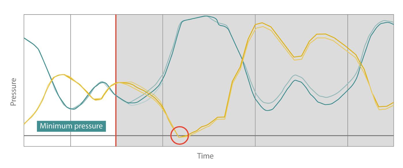
For example, a sudden loss of hydrogen injection does not simply reduce hydrogen concentration. It changes the physical characteristics of the gas moving through the network, increasing resistance and altering pressure profiles as the heavier gas front advances.
Without predictive insight, operators may only become aware of these effects once pressures approach operational limits. At that point, response options may be limited.
Look-ahead projections provide a predictive window into future network behaviour by simulating
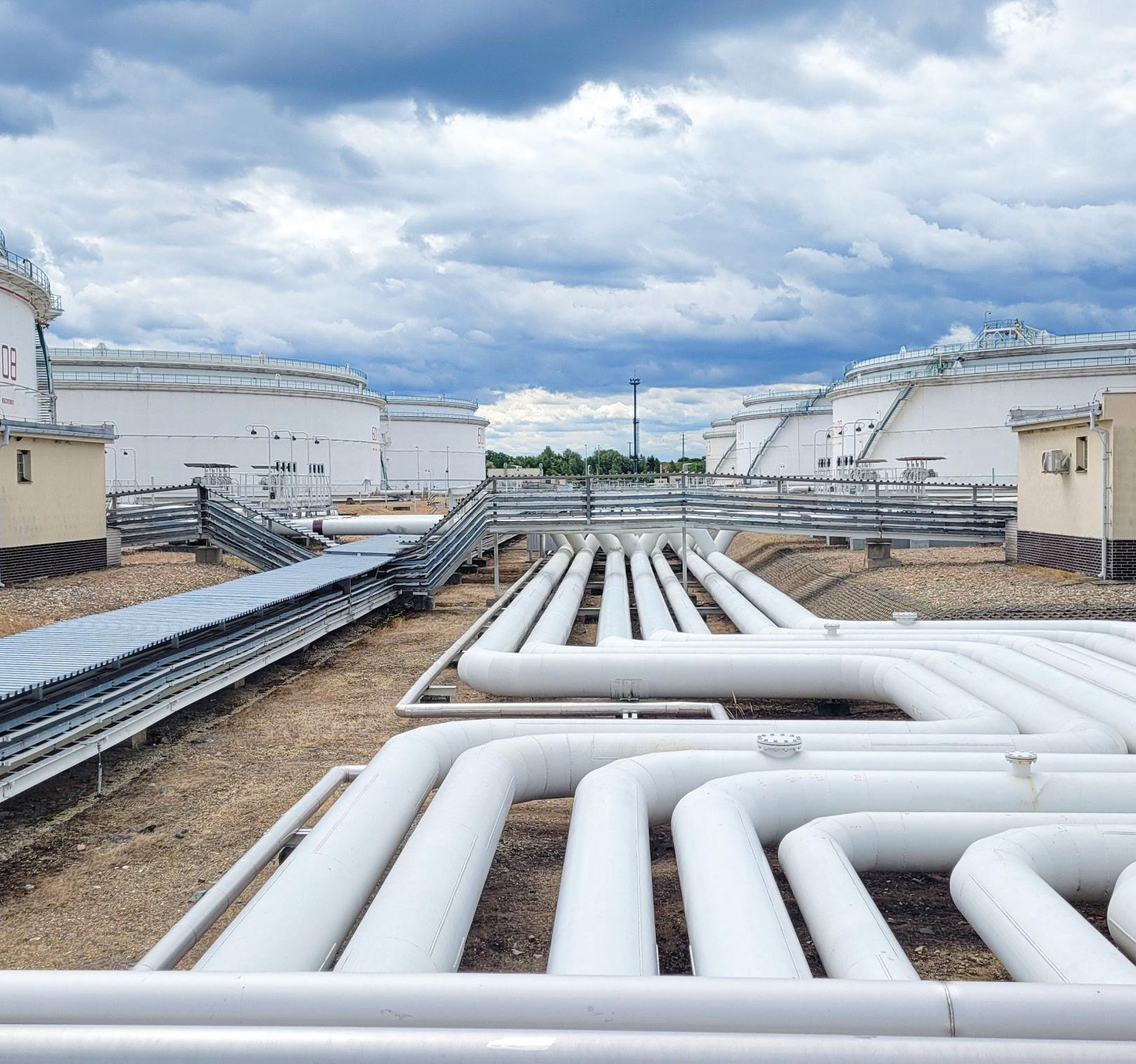
diverse ‘what-if’ scenarios. The process begins with a state initialisation, where the engine pulls the most recent realtime snapshot from the network to serve as a baseline. The simulation then bridges the gap between the live system and the projected operation, modelling the transition from current conditions to the scenario’s starting point. By anchoring offline analysis to live production data, operators can pre-emptively identify potential inventory violations and operational bottlenecks before they manifest in the physical system.
This capability does not replace operator expertise. Instead, it augments decision-making by providing foresight that could otherwise result in delivery shortfalls or unexpected shut-downs.
simultaneously
Operating a blended gas network requires managing a complex set of interdependent physical constraints. Because hydrogen has a lower energy density, operators must increase flow rates to meet consistent energy demands. These elevated flows drive higher gas velocities, which can reach erosional limits within specific valves and fittings. Simultaneously, these operational adjustments are bounded by material integrity thresholds, which strictly limit hydrogen concentrations to prevent embrittlement in repurposed steel pipelines.
Storage behaviour also changes. Gas networks rely on linepack, the energy stored within pressurised pipes, to manage short-term imbalances. Replacing methane with hydrogen reduces the energy content of that stored volume, shrinking the effective buffer available to operators.
Each constraint influences the others. Increasing flow to meet demand may push velocities higher. Reducing hydrogen concentration to protect materials may limit decarbonisation progress. Managing linepack becomes more complex when its energy value is dynamic.
Simulation tools allow these constraints to be assessed together instead of in isolation. By tracking energy, not just volume or pressure, operators gain a clearer understanding of how close the network is to its true operational limits.
Operational complexity is mirrored on the commercial side. Gas billing is based on energy delivery. In traditional networks, this is managed using zonal average calorific values applied across defined geographic areas. This approach assumes gas quality is broadly uniform within each zone. In blended networks, that assumption no longer holds.
When hydrogen or biomethane is injected at multiple points, gas quality varies as it moves through the system. Two customers in the same billing zone may receive gas with materially different energy content at the same time.
Applying a single average value risks systematic overcharging or undercharging. These discrepancies can exceed regulatory tolerances and undermine confidence in billing accuracy.
Installing physical gas quality measurements at every customer connection is not practical. Instead, operators increasingly rely on modelled composition tracking, using flow and network data to calculate the energy delivered to each offtake.
Model-based energy tracking enables a shift away from static billing zones toward more localised insight.
Rather than applying a single average value across a large area, operators can calculate the average energy delivered to each customer over a billing period. Even where meters report only cumulative volume, the corresponding energy value can be derived from the modelled data.
This approach improves regulatory compliance and enhances transparency. Customers are billed for the energy they actually receive, rather than an approximation.
It also provides flexibility. As injection points are added or blend ratios change, the billing methodology adapts automatically, without requiring new zones or additional hardware.
As gas networks evolve, the role of systems and software is changing.
Rather than acting as optional overlays, digital models and analytics are becoming integral to day-to-day operations. They connect distributed measurements, provide predictive insight and support both operational control and commercial processes.
This does not diminish the role of physical infrastructure. Pipelines, valves, regulators and sensors remain essential. Instead, software systems extend their capability, allowing existing assets to operate effectively under new conditions.
In hydrogen-ready networks, intelligence becomes as important as capacity. The ability to understand and manage variability determines whether decarbonisation can proceed without compromising safety or fairness.
Hydrogen and biomethane represent the first stage of gas network diversification. As energy systems continue to evolve, pipelines may be tasked to transport additional products, including synthetic gases and carbon dioxide.
Each new product introduces different physical behaviours and operational constraints. The experience of hydrogen blending highlights a key lesson: adaptability matters more than optimisation for a single fuel.
Networks that invest in flexible, data-driven operating models are better positioned to deal with ongoing changes. Those that rely solely on static assumptions face increasing operational and commercial risk.
The future gas grid will not be defined by one fuel or one technology. It will be defined by how effectively operators can manage complexity and change.
Increasingly, that capability will come not from additional steel in the ground, but from better intelligence running alongside it.

Robert H. Shelton, CEO and President, and Robert M. Hertzberg, Director, H2C Safety Pipe, Inc. comment on how California’s new hydrogen pipeline safety law could help shape hydrogen pipeline safety standards worldwide and establish an integrity-by-design framework.
Hydrogen is among the most promising tools for decarbonising the world’s most difficult-to-abate sectors. From zero-carbon steel and cement, to shipping, aviation fuels, and long-duration energy storage, large-scale hydrogen deployment is essential
to achieving deep economy-wide decarbonisation, where electrification alone is insufficient. Yet the most significant barrier to adoption is neither technological nor economic,

both of which will inevitably improve with experience and scale. It is public confidence.
For hydrogen to scale, communities must be confident that new infrastructure can be deployed safely. Regulators must be assured that risks are understood and managed. Investors and insurers must see predictable performance rather than unknown liabilities. In short, hydrogen pipelines must meet a higher standard of integrity than legacy energy systems, not only because regulators demand it, but because of hydrogen’s unique physical properties.
Unlike natural gas, hydrogen is colourless, odourless and highly diffusive; it has a broad flammability range that increases the consequences of undetected releases and is prone to leakage through materials and joints that are adequate for other molecules. Even small, difficult-to-detect leaks can carry safety and environmental consequences. Traditional pipeline integrity practices, which evolved around periodic inspection and repair, were never designed for a molecule whose risks cannot easily be seen, smelled or intermittently measured.
These realities are further complicated by public perceptions shaped by historic events, despite the fact that when properly engineered and managed, hydrogen can be safer than gasoline, most hydrocarbon fuels, and alternative energy carriers such as ammonia. The aviation industry offers a useful parallel: sustained public confidence was not achieved through assurances alone, but through rigorous safety-by-design, continuous oversight, and transparent performance. Hydrogen infrastructure must adopt the same mindset if it is to earn durable public trust.

For these reasons, integrity management for hydrogen pipelines cannot be an afterthought layered onto conventional designs. It must be engineered into the system from the start.
Pipeline integrity frameworks were developed around hydrocarbons whose risks are typically detectable through pressure loss, odourisation, or visual indicators, even though these measures have proven imperfect over time. In recent years, regulators and policymakers have increasingly focused on methane leakage, environmental impacts, and safety concerns associated with aging pipeline infrastructure. As the energy system evolves, one conclusion is clear: hydrogen demands integrityby-design, not adaptation of legacy frameworks built for other molecules. Hydrogen challenges nearly every assumption embedded in traditional pipeline integrity programmes. Its small molecular size allows it to permeate seals and materials that
Pipeline inspection technology evolves, but the goal remains the same: certainty where decisions matter most.

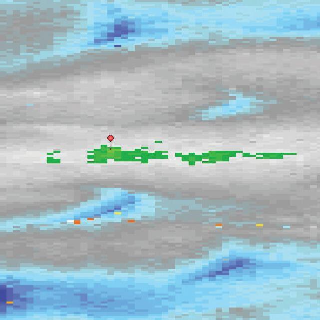
are otherwise considered leak-tight for other gases. Its high diffusivity enables hydrogen to disperse rapidly, often before it can be detected by conventional survey techniques. Hydrogen cannot be odourised without compromising enduse applications and is invisible to infrared and satellite-based tools commonly used to detect methane emissions. As a result, the absence of a detected leak does not reliably indicate the absence of leakage.
These properties make periodic inspection regimes inadequate for hydrogen service. In-line inspection tools, walking surveys and aerial patrols provide only snapshots in time and were never designed to identify low-level, continuous leakage or early-stage degradation driven by hydrogen-specific mechanisms. For hydrogen pipelines, the most consequential failures are not limited to sudden ruptures, but include small, persistent leaks that evade detection, undermine public confidence, and create cumulative safety and environmental risk.
Material performance further complicates the integrity challenge. Many steels used in legacy gas infrastructure are susceptible to hydrogen embrittlement, stress corrosion cracking, and accelerated fatigue. Even where metallic
California SB 804: integrity framework for hydrogen pipelines
SB 804, the Hydrogen Pipeline Safety Act, applies to all intrastate pipelines used solely for the transportation of hydrogen gas. The statute directs the Office of the State Fire Marshal to establish and enforce hydrogen pipeline safety regulations consistent with the following requirements:
Leakage minimisation
A hydrogen pipeline must be designed and constructed to minimise hydrogen leakage to the lowest technically feasible level.
Hydrogen-compatible materials
All materials used in the pipeline must be chemically compatible with hydrogen, including resistance to hydrogeninduced degradation, such as corrosion and embrittlement.
Continuous measurement and monitoring
Hydrogen pipelines must employ continuous measurement and monitoring systems capable of detecting deviations from normal operational parameters.
Limits on retrofitting existing pipelines
Pipelines in existence on or before January 1, 2026, may not be retrofitted for service as hydrogen pipelines. Existing pipeline rights-of-way may, however, be used as a conduit through which a new hydrogen pipeline is installed.
Operational record-keeping and transparency
Pipeline owners must maintain accurate operational records, including hydrogen concentration levels and any instances of hydrogen leakage.
pipelines can be qualified for hydrogen service, joints, welds, and fittings remain potential leakage pathways. Retrofitting existing pipelines for dedicated hydrogen transport introduces additional uncertainty, particularly in densely populated or environmentally sensitive areas that are often the same places where hydrogen is most urgently needed to support industrial decarbonisation, grid resilience, and long-duration energy storage.
Taken together, these factors demand a fundamental shift in how pipeline integrity is defined for hydrogen. Integrity can no longer rely primarily on detecting leaks after they occur. Instead, it must emphasise prevention, containment, and continuous awareness of system performance. This shift from episodic inspection to continuous monitoring reframes pipeline integrity from a compliance exercise into a design discipline.
For communities through which hydrogen pipelines will be built, the challenge of hydrogen infrastructure is not abstract. Pipelines are built alongside schools, neighbourhoods, ports, and industrial centres. To be effective, hydrogen distribution lines must cross sensitive ecosystems, pass beneath city streets, and travel along critical corridors. For these projects to be permitted and accepted, public confidence in hydrogen and in the measures taken to address its risks is essential.
The recognition took legislative form in California’s Hydrogen Pipeline Safety Act (SB 804), which sets the stage for a new generation of hydrogen pipelines built around continuous assurance rather than periodic discovery.
From the outset, California’s approach to hydrogen pipeline safety was guided by a simple premise: the public should not be asked to accept avoidable risks in exchange for climate progress. If hydrogen is to play a central role in decarbonising the economy, it must earn the public’s trust through design choices that make safety visible, verifiable, and enduring.
This perspective reflects lessons from prior energy transitions, where infrastructure was deployed quickly, only to discover later that oversight, monitoring, or accountability lagged behind ambition. Too often, safety standards accommodated legacy systems rather than the realities of new technologies. Hydrogen presents an opportunity to break that pattern.
That conviction shaped the structure of California’s Hydrogen Pipeline Safety Act. Introduced by the chair of the Senate’s hydrogen caucus and co-authored by the chair of the Assembly’s Energy and Natural Resources Committee, the legislation has advanced with unanimous support across every committee and floor vote, backed by members of both political parties, and representatives of industry, labour, and environmental organisations alike. Rather than prescribing a specific technology or locking in today’s solutions, the act establishes clear performance expectations (see sidebar). Hydrogen pipelines must minimise leakage to the lowest technically feasible level, use hydrogen-compatible materials, employ continuous monitoring, and document operational performance over time.








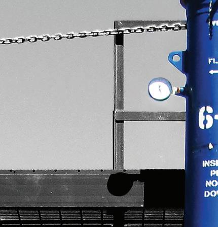























These requirements are not intended to slow development. On the contrary, they provide clear legislative guidance that makes the development of critical hydrogen infrastructure both possible and durable. By setting minimum acceptable expectations early, the law will reduce uncertainty for regulators, communities, and investors.
Just as importantly, the legislation draws a clear line between adaptation and avoidance of risk. It prohibits the reuse of existing pipelines for dedicated hydrogen service while allowing existing rights-of-way to be repurposed by installing new pipelines inside these existing assets, designed explicitly for hydrogen service. In doing so, it balances speed, cost, and safety without asking communities to accept unknown longterm risk.
At its core, this approach reflects a belief that climate leadership and public safety are mutually reinforcing goals. Hydrogen will only scale where people trust it, and trust is built when infrastructure is designed to perform safely throughout its operational life.
Performance-based safety standards matter only if they can be translated into practical engineering decisions. In the case of hydrogen pipelines, California’s Hydrogen Pipeline Safety Act establishes expectations that fundamentally influence how pipelines are designed, constructed, and operated. Meeting these expectations requires moving beyond incremental improvements to legacy systems and adopting architectures conceived specifically around hydrogen’s unique properties.
Minimising leakage begins with recognising that no single component determines integrity. Materials, joints, containment strategies, and monitoring systems must function as an integrated system. Traditional single-wall pipeline designs assume leaks are rare and manageable after the fact. For hydrogen service, that assumption is insufficient.
Translating performance standards into pipeline architecture
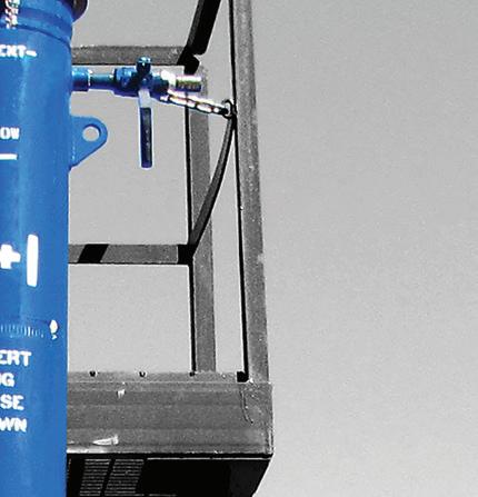
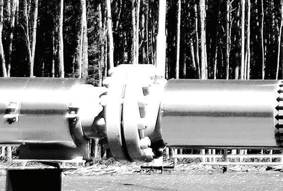
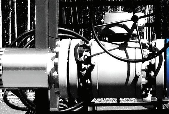
One implication of the measure’s performance standards is a growing interest in secondary containment strategies. By separating hydrogen transport from environmental isolation, dual-containment architectures enable any leakage from the primary carrier pipe to be captured, controlled, and monitored before hydrogen can escape into the surrounding environment. Technologies such as H2C Safety Pipe™ illustrate how this approach can be implemented in practice. This design mirrors containment principles long applied in other regulated industries but represents a significant departure from conventional gas pipeline design.
Material selection is equally central. While certain steels can be qualified for hydrogen service, long-term performance under cyclic pressure and real-world conditions remains a concern. Non-metallic materials such as fibreglass-reinforced polymer pipe, evaluated for more than a decade by US Department of Energy national laboratories and codified under ASME standards for hydrogen service, are immune to corrosion and hydrogen embrittlement. Their use can reduce joints, eliminate corrosion pathways, and lower installation costs, while enabling deployment inside existing rights-of-way.
Continuous monitoring is the third pillar that converts design intent into operational reality. Periodic inspections cannot provide the persistent awareness required for hydrogen pipelines. Systems that continuously detect hydrogen presence allow early intervention, precise localisation, and verifiable data sharing with regulators and stakeholders.
Together, these design choices shift pipeline integrity from a reactive discipline to a preventive one. Rather than relying on inspection intervals and response protocols alone, integrity is embedded directly into the physical and operational structure of the pipeline. Leakage is not treated as an acceptable risk to be managed after detection, but as a condition to be continuously managed, physically contained, and documented as part of normal operation.
This systems-based approach aligns directly with California’s proposed hydrogen pipeline safety legislation. By setting outcome-oriented standards and leaving room for engineering judgment and innovation, the measure encourages solutions that are safer, more resilient, and ultimately more financeable.
H2C Safety Pipe’s dual-containment architecture, continuous monitoring framework, and use of hydrogen-compatible materials illustrate how these principles can be translated into deployable infrastructure that meets both regulatory and market expectations.
The question facing the hydrogen sector is no longer whether hydrogen will play a role in decarbonising the global economy, but whether the infrastructure built to support it will earn the trust required to scale. Pipelines, more than any other delivery system, will determine that outcome. They concentrate public attention and capital investment in ways that demand a higher standard from the outset.
California’s Hydrogen Pipeline Safety Act reflects a growing recognition that hydrogen infrastructure must be governed by principles aligned with hydrogen’s unique physical and social realities. By focusing on leakage minimisation, hydrogencompatible materials, continuous monitoring, and transparent recordkeeping, the legislation reframes pipeline safety as a design discipline rather than a compliance exercise. In doing so, it offers a template that other jurisdictions can adapt to their own regulatory structures and market conditions.
In their respective featured address and technical breakout presentation at the 2026 National Green Hydrogen Congress in Huelva, Spain, the authors emphasised that public confidence will ultimately determine the pace of hydrogen deployment worldwide. Standards that make safety measurable, visible, and verifiable are not barriers to investment. They are prerequisites for it.
As nations race to build the hydrogen economy, the opportunity is not simply to build quickly, but to build wisely. Pipelines designed for integrity from the ground up will define the difference between hydrogen as a promising concept and hydrogen as a durable, trusted backbone of the clean energy system. Integrity by design is not a regional policy choice. It is the foundation upon which a global hydrogen future must be built.

Shelli Myers, Chair, Texas Pipeline Association, USA, comments on the advancements in infrastructure being made in Texas at the moment.
Texas is growing at a phenomenal pace, spurred by enormous advantages that include a central location, a state-of-the-art transportation system, a highly skilled workforce, a comparatively low cost of living, and a pro-business environment. Supporting all that visible growth is the infrastructure that most Texans will never see – an extensive underground network of oil and natural gas pipelines.
More than any other mode of transportation, pipelines quietly and safely deliver the energy that powers our homes, fuels our economy and enables everything from manufacturing and health care to the digital infrastructure that is driving the next generation of innovation. In a state as large and dynamic as Texas, that reliability is not optional; it is foundational to Texas and the entire US.
As Chair of the Texas Pipeline Association and Manager of regulatory compliance at WhiteWater Midstream, I see firsthand how essential this infrastructure is – and how easily it can be overlooked.
Reliability is built, not assumed Texas’ leadership in energy production was intentional, built by generations of innovators, entrepreneurs, elected officials and regulators dedicated to providing a safe, reliable and durable infrastructure – one capable of supporting a population now approaching 32 million.
But reliability does not maintain itself. It requires constant attention, rigorous regulatory compliance, continuous
maintenance and a deep commitment to operational excellence. To that end, pipeline operators invest heavily in safety systems, monitoring technologies and workforce training to ensure the system performs as expected – every single day.
In fact, Texas was the first state in the nation to mandate a comprehensive Pipeline Integrity Management Programme, which is a set of safety-focused requirements and practices that pipeline operators implement to ensure the continued safe and reliable operation of their pipeline infrastructure. It is run in concert with federal management programmes and administered by the Railroad Commission of Texas.
These and other programmes are why pipelines are among the safest and most efficient ways to transport hydrocarbons –and getting safer every year. According to the US Department of Transportation’s Pipeline and Hazardous Materials Safety Administration, total liquid pipeline incidents decreased 13%, or by 42 incidents, since 2020. Looking more closely at the data, incidents affecting people or the environment declined 13%; integrity management incidents were down 33%; and operations and management incidents decreased 22%, says the API and Liquid Energy Pipeline Association’s 2024 ‘Pipeline Performance Report’.
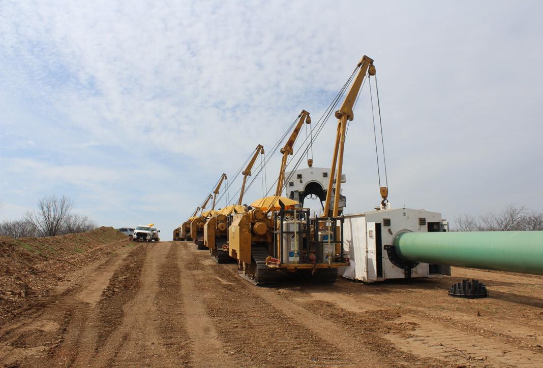
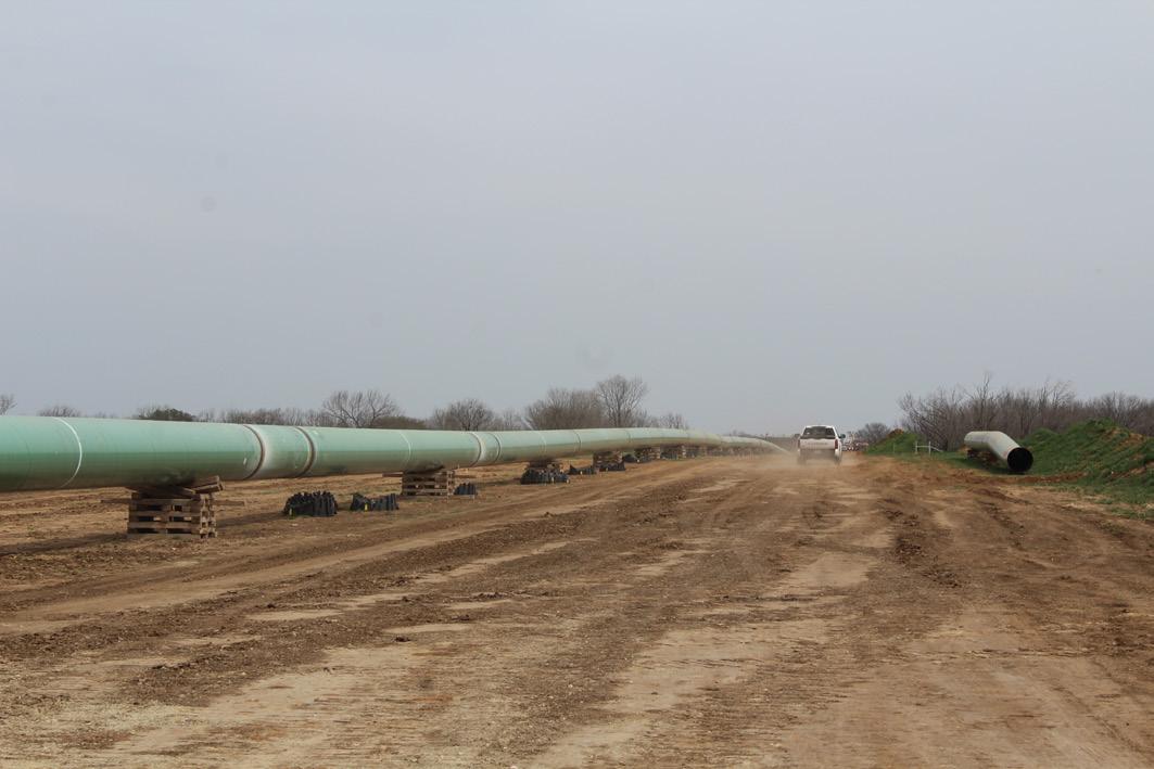
Pipelines make our lives infinitely better on the road. Just 50 miles of a 20 in. pipeline can transport the same volume of hydrocarbons as approximately 1650 tanker trucks – reducing traffic, emissions, road damage and the risk of accidents. Every barrel moved by pipeline is one less barrel of hazardous materials moved by railway through our towns, rail crossings, and busy corridors.
With success, however, comes new pressures. Rapid population growth, expanding power generation needs and rising demand from energy-intensive sectors, such as artificial intelligence and advanced manufacturing, are pushing the system harder than ever before.
And that means more need for natural gas, one of the world’s most reliable, on-demand and resilient energy sources. According to Global Energy Monitor, the US now has the most gas-fired power capacity in development – projects in the announced, pre-construction and construction phases –surpassing China and accounting for nearly one-quarter of the world’s total. More than one-third of this capacity is slated directly to power data centres on-site.
In the US, Texas accounts for nearly a third of the planned buildout, with 80.6 GW of the gas-fired power capacity in development – more than the next seven states combined and nearly a four-fold increase over the last year. Meeting that demand will require added pipeline infrastructure in a market already near capacity, where constraints are causing bottlenecks and increasingly complex gas supply dynamics.
For example, a significant share of Texas’ marginal gas production comes from the Permian Basin, one of the world’s most prolific oil- and gas-producing regions. When production approaches the limits of available egress capacity, constraints emerge – not because gas is unavailable, but because it becomes more difficult to move efficiently to the right place at the right time without adequate infrastructure. The result is reduced operational flexibility and greater price volatility, particularly during periods of peak demand.
In response, Texas pipeline operators are building and expanding additional capacity in a state that already maintains nearly 473 000 total pipeline miles; yet it is not enough.
Until new takeaway and intrastate reinforcements are fully in service, the system will remain under stress – especially during extreme weather events when reliability matters the most.
Compounding these operational challenges are growing policy and permitting headwinds. Pipeline projects face longer approval timelines, increasingly complex siting requirements and rising local opposition – often driven by misunderstanding rather than facts. These factors widen the gap between what Texans expect from the energy system and what it takes to build and maintain the infrastructure that delivers it.
Although Texas has long been a model for balancing safety, environmental protection and economic growth, preserving that balance is critical to ensuring that infrastructure is able to keep pace with demand – especially as federal policies evolve and local pressures increase.
Although Texas faces fewer federal permitting constraints for its intrastate pipelines than those regulated at the federal level, operators face the same public scrutiny and investor uncertainty. Like other energy infrastructure, pipeline planning is capital-intensive: investment decisions are made on a multidecade horizon, not a quarterly one.
These factors and others can stymie the build-out of highly needed capacity. For that reason, predictable, sciencebased regulation and frequent, transparent public outreach is essential.
matters more than ever
Operators are not asking for lack of regulation; they are asking for predictability, consistency and a reliance on operational technical expertise. When rules are clear and grounded in science, operators can invest with confidence, regulators can do their jobs effectively and communities can engage constructively.
One of the most important lessons I have learned in this industry is that silence can result in misunderstanding. Pipelines may be out of sight, but they must be top of mind when it comes to public engagement.
Public understanding of the industry is vital. We must share that the Texas midstream industry supports economic growth, enables innovation and provides more than 234 000 highly skilled, well-paying jobs, sustaining families across the state.
We must ensure that the public is aware that without
Fuel shortages would ripple across the nation, manufacturing costs would spike, commuters would be stopped in their tracks and state and local budgets would shrink.
In other words, catastrophic results for all.
Operators, associations and regulators all have a role to play in explaining how pipeline systems work, how safety is managed and why infrastructure matters to everyday life. Transparency and trust go hand in hand when building public support for an industry not a single one of us can live without.
1. Census: Texas led US in population growth in 2025, but immigration slowed. https://www.houstonpublicmedia.org/articles/news/texas/2026/01/28/541916/ texas-population-2025-census/
2. RRC’s Oversight & Safety Programme, Railroad Commission of Texas. https:// www.rrc.texas.gov/pipeline-safety/
3. 2024 Pipeline Performance Report, API, Liquid Energy Pipeline Association, Spring 2025. https://info.api.org/wp-content/uploads/2025/04/2024-API-LEPA-PipelineExcellence-Performance-Report-2023-2025-Strategic-Plan-2.pdf?_gl=1*awnves*_ gcl_au*MjE0Mzc5ODU2MS4xNzM4NzkzMzU4*_ga*Mjk4NTk0NDk1LjE2NzUyNz U3NTc.*_ga_4GE2RKSLYW*MTc0NTU4OTcyMi4zNTMuMS4xNzQ1NTg5NzI4LjU 0LjAuMA..
4. Betting big on data centres, US now leads world for new gas power development, Global Energy Monitor. https://globalenergymonitor.org/ report/betting-big-on-data-centers-u-s-now-leads-world-for-new-gaspower-development/?utm_campaign=Newsletter&utm_medium=email&_ hsenc=p2ANqtz-9mfZat2Zj0VUBPTozFUU7hkRHaU9hiyVV6C_bXRuQCIQQlGJOl YWF85g6YK7DmbSFaLZDmv--nN9tunN0zdKGr5t2jDQ&_hsmi=401257045&utm_ content=401257045&utm_source=hs_email
5. Railroad Commission of Texas, pipeline mileage. https://www.rrc.texas.gov/ pipeline-safety/reports/texas-pipeline-system-mileage/
6. Economic Impact of the Texas Pipeline Industry, Texas Tech University, Centre


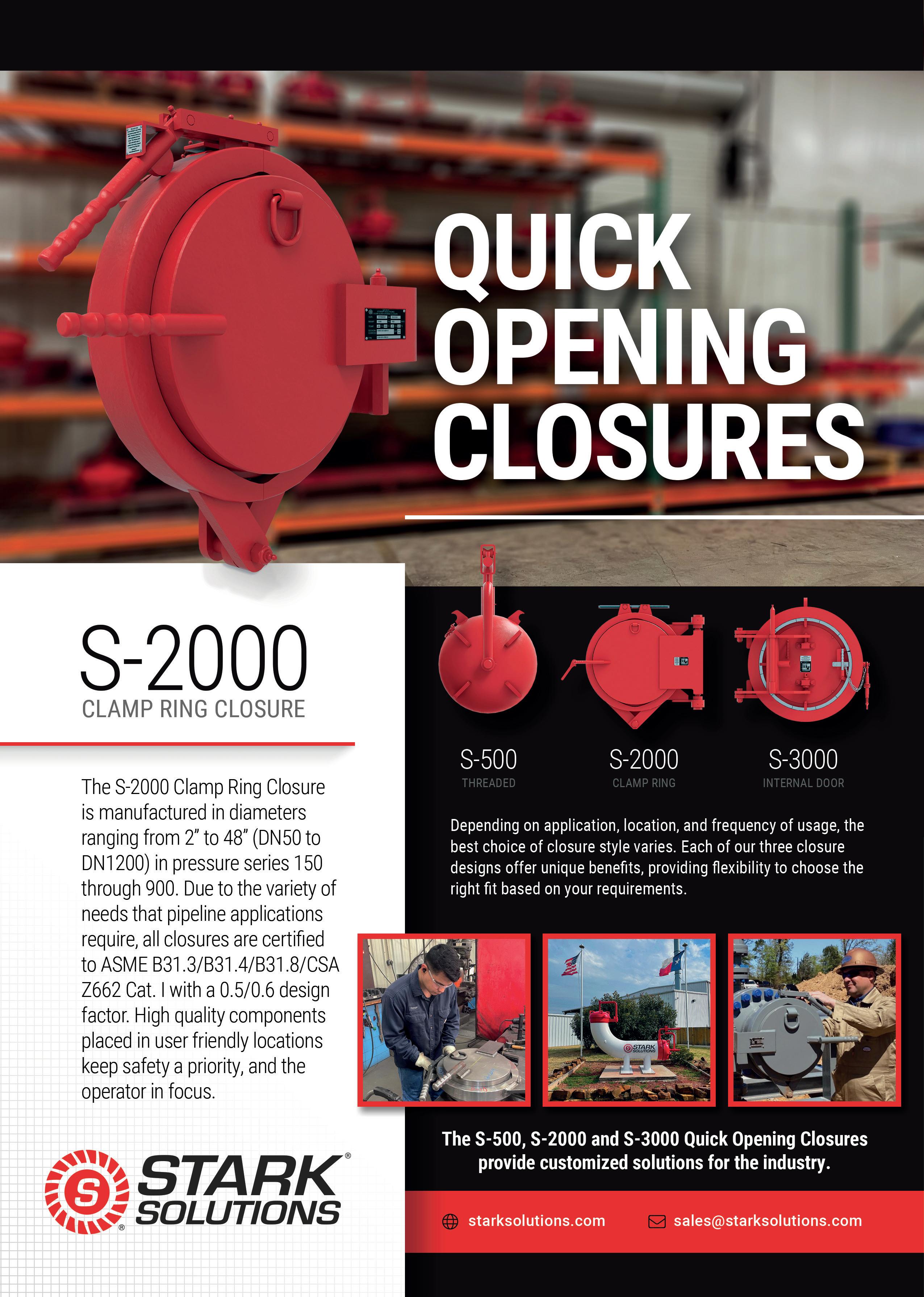
Quick-opening closures, an alternative to blind flanges are essential components for allowing easy access to many pressure-containing systems used across pipeline, processing, and energy infrastructure. These systems require zeroleakage sealing performance while allowing operators to safely access equipment such as pig launchers, receivers, filters, and pressure vessels. In such applications, closures must maintain sealing integrity through repeated operating cycles, varying pressure conditions, and temperature fluctuations while still allowing efficient opening and closing procedures.
Although many closure configurations exist, scaling these systems to large diameters introduces design and fabrication challenges. Distortion, dimensional tolerances, and sealing reliability become increasingly difficult to control as component size increases.
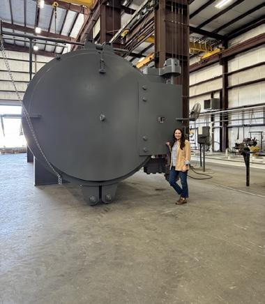
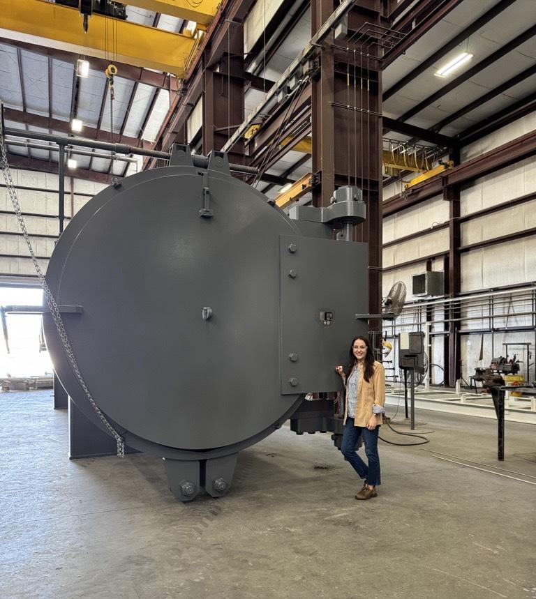
A recent engineering project managed by Stark Solutions addressed this challenge through the development of a 90 in. bore-seal O-ring clamp-style quick opening closure. This demonstrated that large-diameter closures can maintain a reliable seal while preserving the operational advantages of bore seal clamp-style designs.
In pressure-containing systems, sealing performance is critical for personnel safety, environmental protection, and uninterrupted plant operations. Leakage in these systems can introduce safety risks, regulatory concerns, and costly downtime.

Among available sealing technologies, O-rings remain one of the most widely used solutions due to their simplicity, reliability, lower cost, and proven performance. An O-ring gland creates a seal through controlled elastomeric compression between mating surfaces. When properly designed, O-rings provide effective sealing under both internal pressure and vacuum conditions.
The industry has traditionally relied on internal door-style closures using lip seals for large outside-diameter systems or compressed-seal options.
Lip seals operate differently from O-rings. Rather than relying purely on compression within a defined gland, they incorporate a pressure energised sealing lip that reacts dynamically to pressure conditions. In many designs, increased internal pressure enhances the sealing effect. Lip seals are also more tolerant of dimensional variation caused by fabrication processes such as welding and heat treatment.
Compressed seal closures use a face-sealing O-ring design that uses angled clamping faces which drive the closure hub and door together. This requires significant force to close the clamps and ensure they remain closed, as that operation is what creates and maintains the O-ring compression.
While Internal Door lip seal closures and compressed seal O-ring closures offer advantages in distortion tolerance, they also introduce operational complexity in applications of this size.
In an internal door-style closure design, the operator needs to ensure that the heavy door (upwards of 16 000 lbs in

this case) was properly centred to guide it into the hub. On a compressed seal design, the operator needs to mechanically compress the seal, requiring large amounts of consistent and
continual force equally applied via the clamp ring, normally achieved by use of a top and bottom operating screws which must be timed simultaneously.
Due to this, opening and closing procedures may be more difficult, slower, and maintenance tasks can require additional steps compared with alternative closure designs.
Bore seal clamp-style closures offer several operational advantages in horizontal applications requiring frequent access. These include:
) Faster opening and closing cycles.
) Simplified operation for field personnel.
) Reduced maintenance complexity.
) Improved accessibility for inspection or service.
For facilities that must open and close pressure systems regularly, these operational efficiencies can be highly valuable.
In this project, the required diameter approached 90 in., a size range where closures would not normally be considered, especially bore-seal O-ring clamp closures, which had not traditionally been implemented due to technology limitations.
Scaling a bore-seal O-ring closure to a diameter approaching 90 in. introduces technical challenges.
As component diameter increases, dimensional tolerances become increasingly sensitive to distortion. Welding the closure hub to a pressure vessel can introduce out-ofroundness, axial displacement and localised deformation. Post-weld heat treatment can further alter the geometry of the welded assembly.
Even a few thousandths of an inch of change in roundness can translate into significant dimensional deviations at large diameters. These variations can directly affect the door and hub fitment, as well as O-ring compression, which must remain within a defined range to ensure proper sealing performance.
Large-diameter pressure components represent substantial material and fabrication investments. Raw materials suitable for components of this scale often require extended procurement lead times. Machining operations can involve significant labour hours and specialised equipment.
If distortion during fabrication results in unacceptable dimensional variation, the resulting rework or component replacement can have serious cost and schedule implications. In some cases of this magnitude, the scale of the risks and the associated responsibilities can influence manufacturers not to participate in projects of this size.
Managing and compensating for fabrication-induced distortion therefore became the central engineering challenge of the project.
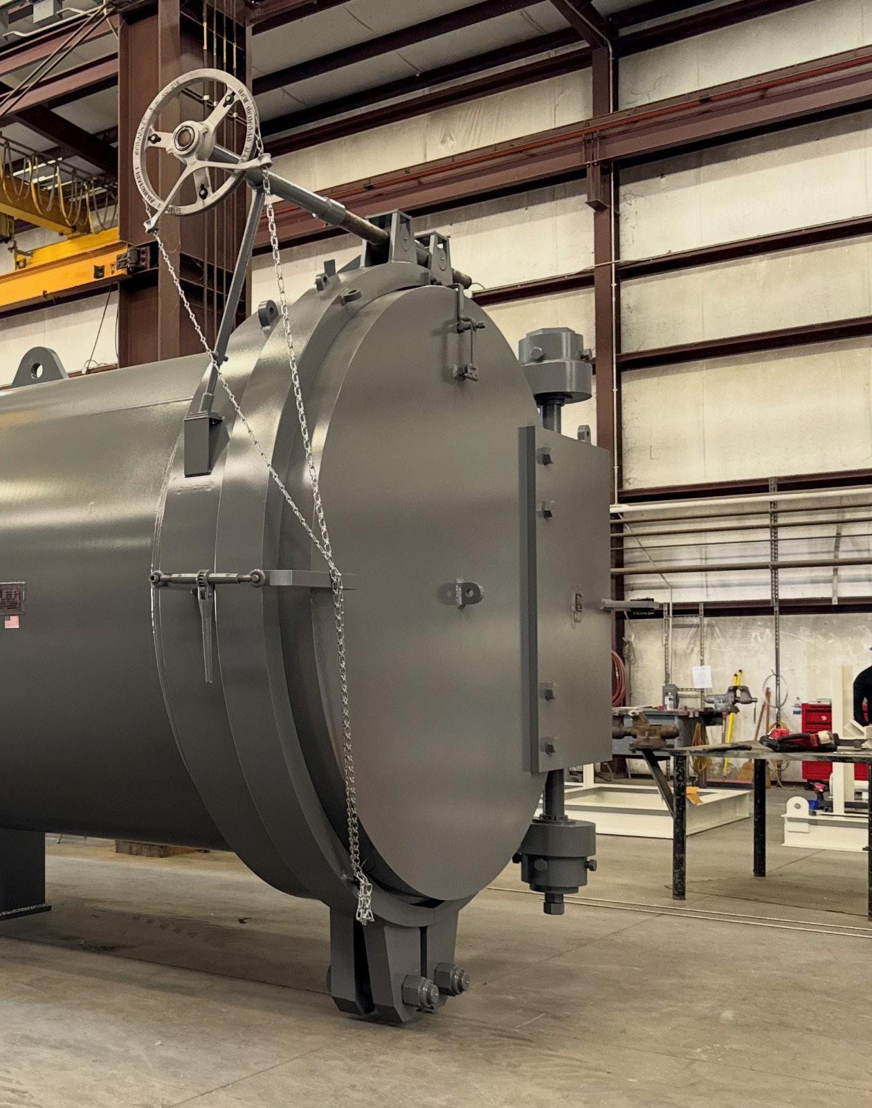
The solution was developed around the Stark designed S-2000 clamp-style closure. For the safety of the operator, the clamp style closure door swings on a horizontal axis, so one is never
required to stand in front of the Door. An integrated Pressure Alert Valve (PAV) provides a level of safety because prior to the clamp being released, the PAV must be removed, as it secures the clamps in place when in the closed position. After depressurisation and the PAV stem removal, the opening is performed by actuating a single operating screw to disengage the clamp from the door and hub, then actuating the door open.
The closure consists of three primary pressure-retaining components:
) Hub: mounted to the vessel and containing the O-ring sealing gland.
) Door: providing the outer-diameter sealing surface.
) Clamp segments: securing the door to the hub during operation.
Each pressure-containing element was designed and analysed according to applicable ASME pressure vessel code requirements, ensuring compliance with required stress limits and safety factors.
However, meeting dimensional and sealing requirements meant additional strategies beyond standard machining practices.
After the hub was welded to the pressure vessel and post-weld heat treatment was completed, dimensional verification was performed using high-resolution laser metrology which has accuracy within one to two thousandths of an inch.
Laser scanning technology captured detailed measurements of the installed hub geometry, including overall roundness, any localised distortion and dimensional deviations from nominal design geometry.
These measurements were used to generate an accurate three-dimensional model of the installed component.
The closure door was machined to match the measured geometry of the hub postfabrication and post weld heat treatment rather than the nominal pre-weld design dimensions.
By incorporating the laser measurement data into the machining process, the door geometry accounted for any warpage introduced during welding and heat treatment. This ensured that the sealing surfaces maintained the required compression characteristics for the O-ring.
This distortion-compensated machining approach allowed precise sealing geometry to be maintained despite dimensional variation in the installed hub.
Historically, uncertainty surrounding warpage during fabrication has been one of the primary reasons that bore-seal O-ring closures were rarely implemented on large diameters. By directly measuring the installed geometry and adapting machining processes accordingly, the innovative project addressed that limitation.
The door was machined to preliminary finished dimensions while the final measurements of the hub were being obtained, ensuring optimal alignment. This strategy minimised the time required for the door’s final machining, which was completed in a single day. The subsequent assembly of the door and
and
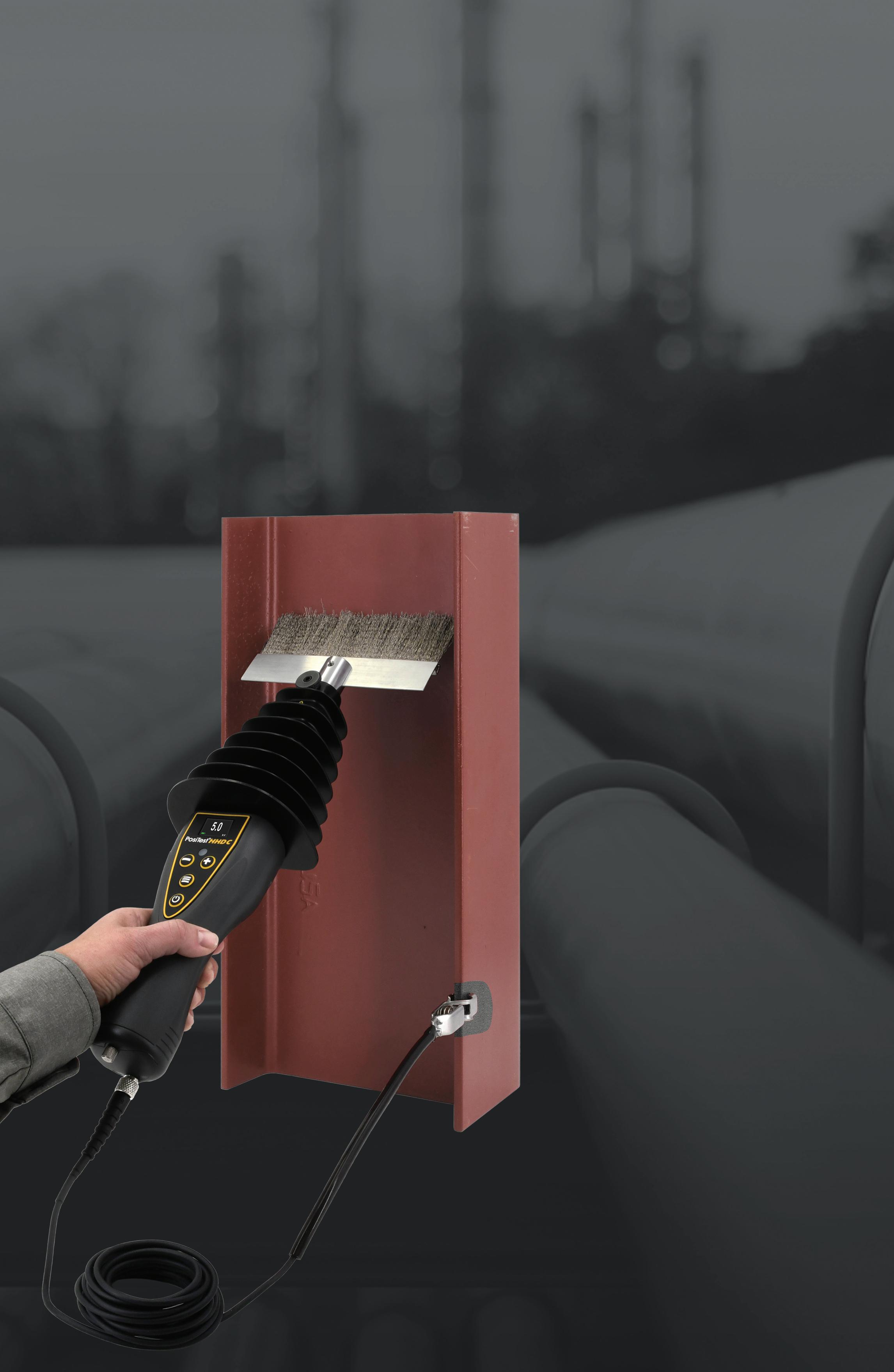
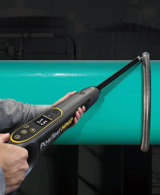
n Lightweight, one-piece ergonomic design provides comfortable all-day use
n One wand covers the entire voltage range from 0.5 to 30 kV
n Up to 16 hours of battery life—powerful Li-ion batteries fit neatly within the compact wand handle eliminating the need for a separate battery box
n Built-in Certified Voltmeter and Voltage Calculator feature
n Industry standard connectors and adaptors provide compatibility with nearly all existing electrodes

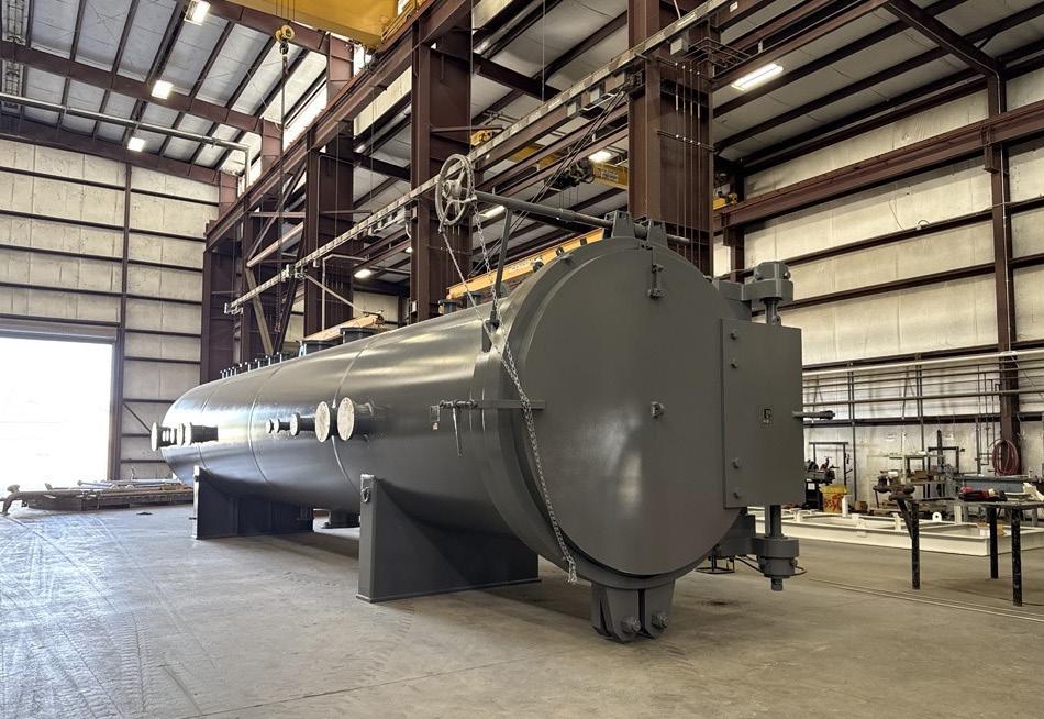
large-diameter pressure access system design. Historically, quick-opening closures of this size have been avoided

IPLOCA_Ad_60thAnniversary_Palladian_210x146mm_300dpi.pdf 1 16/02/2026 12:13





Matthias Hilvert and Thomas Beuker, ROSEN Group, introduce the new RoCD EMAT-C Ultra Service, which is built on proven EMAT-C technology.
Effective pipeline integrity management relies on a broad spectrum of inline inspection (ILI) technologies that enable operators to confidently detect, classify, and size anomalies. These tools form the core of modern integrity management programmes, supporting informed decisions regarding maintenance activities, such as hydrotesting and excavation planning. As pipeline networks grow in complexity, the need for optimised inspection approaches becomes increasingly critical.
The introduction of EMAT-C Ultra technology represents a major step forward in addressing crack-related threats. Based on the proven EMAT-C technology, the new system seamlessly integrates into established operational workflows, while providing substantial performance enhancements. Its doubled sensor coverage and dual sound-path methodology – capturing signals clockwise (cw) and counterclockwise (ccw) – significantly strengthen the reliability of crack detection for critical dimensions, achieving 95% probability of detection (POD) and surpassing current industry expectations.
This article compares the performance of EMAT-C Ultra with industry benchmarks that validate its effectiveness in advancing pipeline integrity management.
The electro-magnetic acoustic transducer (EMAT) technology
EMAT technology is a well-established and further growing method for detecting cracks and crack-like defects in pipelines. Since its commercial introduction in 2006, EMAT has steadily become an essential tool in pipeline integrity management, thanks to its ability to generate and analyse ultrasonic sound waves without requiring a coupling medium.
EMAT operates using two physical phenomena: the Lorentz force and magnetostriction. These effects are produced by alternating currents interacting with a static magnetic field, allowing the system to generate ultrasonic waves.1 When these waves encounter cracks or defects in the base material or longitudinal seam welds, they reflect back, and the tool’s echo channel records these signals (Figure 1). A large number of overlapping transducers are arranged on the inspection tool to generate a high-resolution image of the pipeline. Due to the short propagation distance of the waves between the measuring elements, this design ensures high signal quality, forming the basis for accurately determining the position and dimensions of flaws.2 Unlike traditional piezoelectric ultrasound, which captures only a single frequency, EMAT
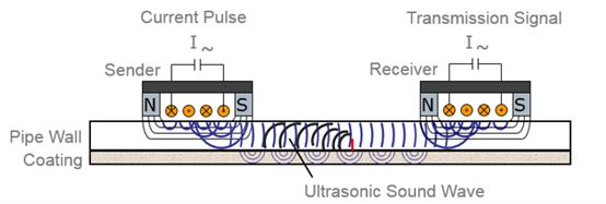
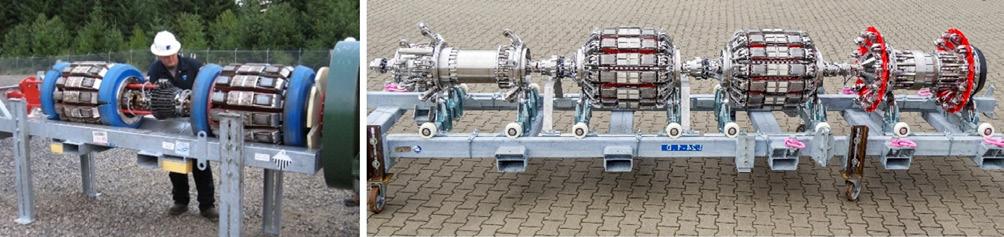
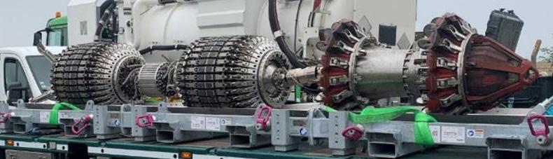
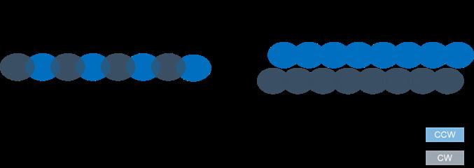
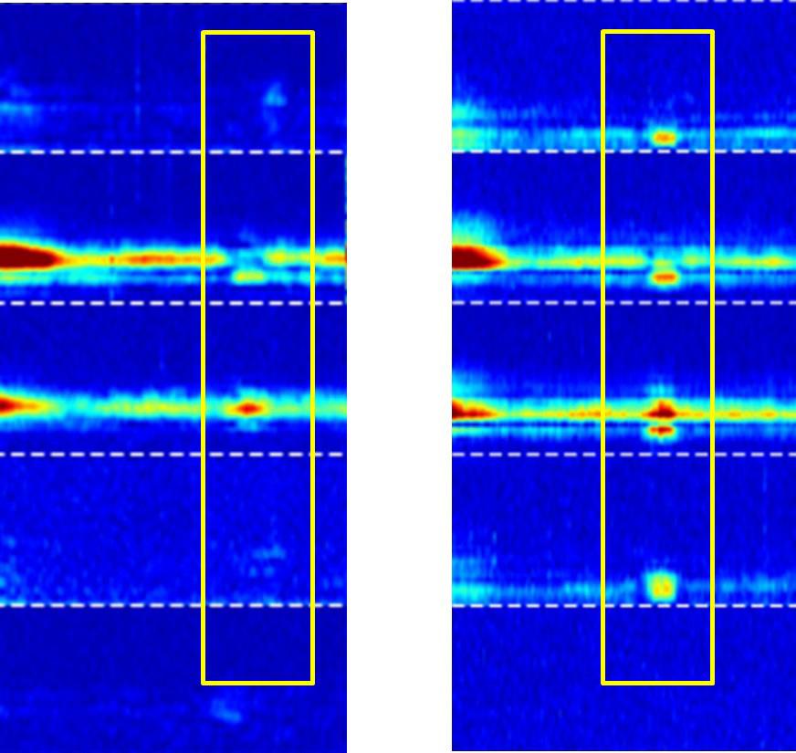
records the entire frequency spectrum. This broader dataset allows for more detailed analysis, enabling accurate identification and sizing of linear anomalies.
This highly versatile technology can inspect a wide range of pipeline diameters (10 - 48 in.). Its performance has been rigorously validated through numerous industry pull tests and case studies, ensuring consistent and reliable results in the field.
Over the past two decades, more than 136 000 miles (220 000 km) of pipeline data have been analysed, highlighting its critical role in pipeline integrity. This large volume of inspected pipeline miles is accompanied by a large number of field verification results, which are invaluable for improving and further developing the technology. ROSEN has a treasure trove of over 10 000 reported anomalies that have been verified in the field. This information is an important source for using modern artificial intelligence (AI) technologies for the continuous development and optimisation of data analysis.3
For nearly 20 years, ROSEN’s RoCD EMAT-C tools have been essential to pipeline integrity management. They have evolved from early Cup-Tool designs (Figure 2) with integrated EMAT sensors into robust systems that address challenges such as high gas flow conditions with a speed control valve and wheel supported sensor suspension.
Today, modern EMAT-C tools provide low-noise data, improved run behaviour, advanced electronics, and durable sensors capable of operating over hundreds of kilometres (Figure 3).
Similar to earlier versions, today’s tools use two measurement segments, each covering slightly over 50% of the circumference. This achieves an overlap of 110 - 125%, depending on the tool size, ensuring full coverage even with rotation. The newest generation, EMAT-C Ultra, builds on this foundation with further optimised capabilities, including a further optimised sensor system. One of the key enhancements is the increased coverage to 200%.
This is achieved through a new sensor arrangement that ensures every point on the pipeline is inspected in both clockwise and counterclockwise directions (Figure 4). This dual-directional inspection method enhances the detection of smaller, more complex flaws that other technologies may miss.
Another critical advancement is the separation of sender and receiver sensors onto independent carriers. This configuration allows each channel to move freely and maintain optimal contact with the pipe wall, even in challenging areas such as long seam welds. Dual-sided scanning ensures that, even if a sensor carrier is momentarily influenced by the geometry of the longitudinal weld, crack-like indications are still captured by multiple sensor channels (Figure 5). This redundancy enables the detection and identification of smaller flaws in the pipe body and longitudinal welds.
The RoCD EMAT-C Ultra Service represents a significant evolution of the well-established and reliable RoCD EMAT-C Service. It incorporates advanced sensor technology to achieve enhanced crack detection and resolution (Figure 6). These improvements enable the detection of shorter and shallower linear indications, bringing the service’s resolution and
Redefining decoupler performance without missing a beat.
Dairyland’s PCRX delivers the full functionality of a standard decoupler while eliminating capacitance delays during interrupted surveys. By remaining connected during testing, PCRX ensures accurate, timely potential measurements while maintaining continuous protection. Personnel and critical assets stay safeguarded with the rugged over-voltage protection, AC interference mitigation, CP isolation, and safety grounding you expect from Dairyland decoupling products.
detection thresholds close to those offered by state-of-the-art UTCD technologies.
One of the key advancements of the RoCD EMAT-C Ultra Service is its enhanced detection reliability for linear indications (Figure 7). The POD has been improved by up to 95%, exceeding current industry standards. The combination of higher sensitivity and dual-direction coverage (clockwise

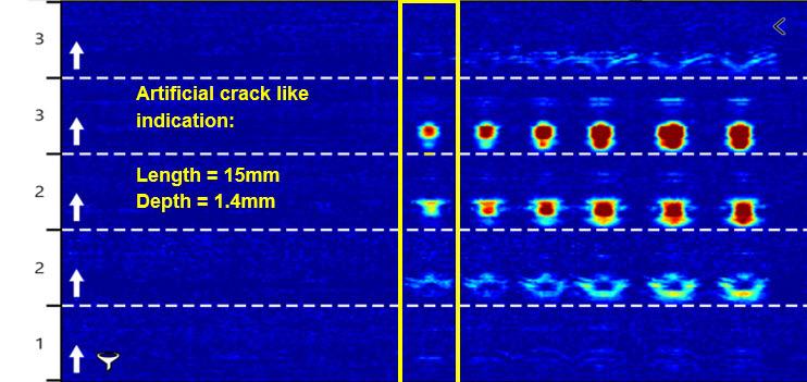
Figure 6. Example of a short and shallow feature detected by EMAT-C Ultra. The channels alternate between cw and ccw orientation.
and counterclockwise) significantly increases the probability of identifying all common types of internal and external axial cracks and crack-like defects.
Another advantage of the application’s dual sound path is improved detection of tilted cracks. These cracks do not follow a radial direction, rather, they are tilted away from the surface into the pipe wall (Figure 8).
Tilted cracks usually reflect better on one side than the other. This makes a tilted or inclined crack that is only addressed from one side more difficult to detect and/or identify. Detecting the crack from both sides provides a more complete picture and improves identification and depth sizing capabilities. Figure 9 shows data from a series of artificial cracks with increasing inclination from left to right. While the signal from one channel (clockwise in this case) becomes slightly weaker, the signal from the other channel remains stable.
The RoCD EMAT-C Ultra Service ensures seamless compatibility with existing RoCD EMAT-C workflows, enabling operators to integrate the enhanced capabilities without disruption. The consistent advancement of sensor technology and methodology solidifies EMAT-C Ultra as a practical solution for pipeline crack detection and continues the history of collected EMAT-C data for a safe and reliable pipeline assessment.
EMAT-C Ultra is a fully operational technology that has already been used for pipeline inspections of various diameters from 10 to 42 in. Before any new ROSEN technology enters service, it undergoes a comprehensive validation process aligned with API 1163 to ensure safe operation and compliance with all performance requirements.
Table 1. Statistics according to Clopper Pearson of the pull test results analysis for pipe body (PB) and long seam (LS)
This validation was carried out at the ROSEN Test Centre in Lingen, Germany (Figure 10), which is one of the world’s largest testing facilities, spanning 108 000 m2 and containing over 9300 m of test pipelines ranging from 3 to 56 in. in diameter. It is equipped to simulate a wide range of pipeline anomalies.
For the EMAT-C Ultra validation, eight fully operational tools (10 - 42 in.) were used, and pull tests were performed across all diameters, covering wall thicknesses ranging from 3.9 mm (0.154 in.) to 13.1 mm (0.516 in.).
Planar flaws were machined as narrow, rectangular EDM notches in test spools of all diameters to assess the RoCD EMAT-C Ultra Service. The inspection tool was pulled



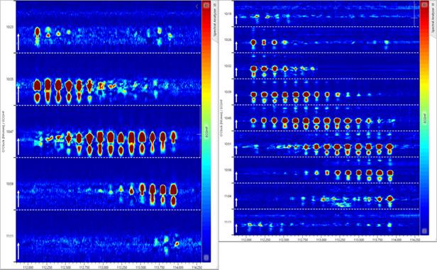

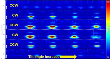
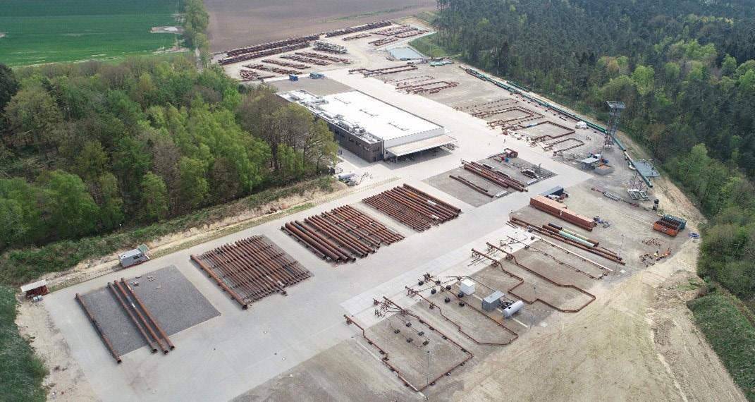
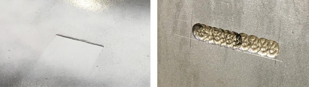
through the pipe multiple times to ensure measurement repeatability. In addition to these classic notches, modern test spools can also contain synthetic anomalies with precisely defined morphology, size, and orientation. For EMAT-C Ultra evaluations, synthetic planar and volumetric flaws were included, such as those mimicking sharp edged or general corrosion defects (Figure 11).
To verify EMAT-C Ultra, 512 pull tests were performed across multiple pipeline diameters. The large number of anomalies in the test pipes generated 127 930 anomaly signals, providing a robust dataset for evaluation. This extensive dataset enabled statistically solid conclusions and confirmed the tool’s reliability and performance across diverse operational conditions.
The data were analysed using a workflow similar to that of a standard pipeline evaluation to ensure the results reflect realistic inspection conditions.
For the calculation of the POD and POI, one-sided Clopper-Pearson binomial proportion confidence intervals were chosen as the statistical approach. This ensured statistically significant results with a guaranteed confidence level.4
Table 1, for example, shows the statistics for POD and POI in the pipe body and long seam according to Clopper-Pearson for the minimal detectable feature.
Based on a dataset comprising over 127 930 anomaly signals, this analysis derives a conservative and reliable specification for the new EMAT-C Ultra technology (Table 2). The specification is applicable to wall thicknesses ranging from 3.9 mm (0.154 in.) to 13.1 mm (0.516 in.) and has a POI of 90% for all common types of radial and longitudinal cracks, terminating on internal or external wall surfaces, including the weld bead.
Managing pipeline integrity is essential for safety and operational reliability. RoCD EMAT-C Ultra is a major advancement, that overcomes the limitations of previous inspection methods. It features 200% sensor coverage and dual sound-path detection. With its higher sensitivity and POD of up to 95%, as well as its ability to seamlessly integrate into existing integrity workflows, RoCD EMAT-C Ultra not only meets, but exceeds, industry expectations. The results presented here confirm RoCD EMAT-C Ultra’s capability to enhance pipeline inspection practices and promote safer, more efficient operations.
1. UPADHYAYA, C., GARTH, R., KANIA, A., SCHARTNER, M., HOEVING, T., MORITZ, BEUKER, T., and VOSS, J., ‘Development of an ILI Service for Heavy Wall Pipelines Based on EMAT Technology’, IPC Calgary 2024.
2. KATZ, D., POTTS, S., BEUKER, T., GRILLENBERGER, J., and WEBER, R., ‘EMAT as a basis for a comprehensive system wide crack management program’, IPC Calgary 2018.
3. EULE, S., BEUKER, T., and PAIN, N., ‘Enhancing EMAT Crack Detection Services Using State of the Art Deep Learning’, PPIM Houston 2023.
4. HOENING, P., and STUBBE, T., ‘Technical ILI System – Verification Versus Validation Based on Sound Engineering Practice Solely on Industry Recognized and Standardized Methodology’, IPC Calgary 2024.

Manuel
Stress corrosion cracking (SCC) remains one of the most complex threats to liquid pipelines, demanding more than periodic inspection to ensure long-term integrity. The authors explore how high-resolution ultrasonic technology, signal-to-signal analytics, and close operator–in-line inspection (ILI) collaboration can transform SCC management from reactive repair programmes into predictive, data-driven integrity planning that extends pipeline lifespan.
SCC remains one of the most technically demanding threats facing liquid pipeline operators. SCC can appear in axial and circumferential orientations, often forming complex, interacting colonies with branching ‘spider web’ morphologies making detection, sizing, growth assessment, and repair prioritisation significantly more challenging.
For operators managing mature pipeline systems, SCC is simply not a defect mechanism to monitor, it is a longterm integrity risk that demands continuous technological
advancement, disciplined data analysis, and close collaboration between operator and ILI providers.
Spanning nearly three decades, one European refined product pipeline network has shown how integrating high-resolution ultrasonic inspection, signal-to-signal run comparisons, statistical validation, and custom analytical tools can transform SCC management, from reactive repairs to predictive, data-driven integrity planning.
A complex network and an evolving threat
The network, transporting gasoline, diesel, jet fuel, and naphtha through 10 - 16 in. pipelines, was built primarily in the late 1960s with expansions in the early 1990s. It features diverse pipe grades and construction methods including longitudinally welded DSAW, seamless, spiral-welded, and HFI ERW pipe with coatings ranging from coal tar enamel to modern three-layer polyethylene.
In the late 1990s, one of the pipelines experienced two ruptures attributed to near neutral pH SCC. Operational mitigations, such as pressure cycle limits and optimised cathodic protection, were implemented, alongside regulatorymandated crack-focused inspections and structured repair programmes. Yet mitigation alone could not address existing cracks – accurate detection, characterisation, and ongoing monitoring became essential to ensure long-term pipeline safety.
The evolution of ultrasonic crack detection
Early crack inspections relied on emerging ultrasonic technologies whose performance characteristics were still
developing. Verification required extensive excavation programmes to validate findings, sometimes involving exploratory digs to confirm tool capabilities.
Ultrasonic crack detection tools operate using pulse echo technology. Angled piezoelectric transducers generate a shear wave that propagates through the pipe wall. When the wave encounters a radial crack, a strong ‘corner echo’ reflection returns to the sensor, allowing detection and depth estimation.
While effective for radially oriented cracks, conventional pulse echo technology has geometric limitations. Complex crack morphologies tilted features, skewed orientations beyond tool specification challenge depth sizing accuracy. Furthermore, tools configured for axial crack detection are not designed for circumferential cracking, requiring separate inspection configurations when both orientations are present.
As ultrasonic technology matured, the most significant advancement came through high-resolution sensor design. By reducing circumferential sensor spacing from 10 mm to 5 mm, inspection systems effectively doubled data density around the pipe circumference. This increased redundancy improved the likelihood of capturing optimal corner echoes and enhanced characterisation of crack morphology.
Successive inspections reported a substantial increase in crack counts. Importantly, this did not indicate accelerated degradation, but rather reflected improved detection capability. Enhanced resolution provided clearer visibility into crack colonies that had previously been only partially characterised. While genuine crack growth contributed to the increase, the primary driver was the ability to identify and define features with greater accuracy and detail.

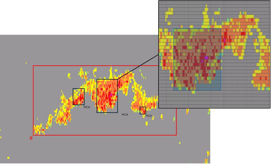
Repeated inspection is essential for determining whether cracks are growing and whether mitigation measures are effective. Traditionally, operators have relied on list-based comparisons, matching reported anomalies from one inspection to the next.
However, such comparisons can be misleading. Differences in detection thresholds, sizing algorithms, tool tolerances, operating conditions during inspection, and analysis methodologies can all influence reported dimensions. A simple comparison of depth values between two reports does not necessarily reflect real growth.
To overcome these limitations, a signal-to-signal comparison methodology was adopted. Rather than relying solely on reported defect


lists, this approach examines the raw ultrasonic signals from consecutive inspections.
The first step is establishing anomalies comparability based on the recorded amplitudes or the non-time dependent features. Because ultrasonic crack sizing is amplitude-based, amplitude consistency between runs must be validated. Manufacturing-related anomalies are considered static and not expected to grow, serving as control features. Histogram analysis comparing amplitude and manufacturingrelated anomalies distributions from consecutive inspections can reveal systematic bias. If these anomalies show consistent depth shifts outside expected tolerances, it suggests measurement bias rather than actual crack growth.
Depth differences are evaluated against combined tool tolerances, calculated using the known depth accuracies of each inspection tool. Only deviations exceeding this comparison tolerance are considered significant.
Newly reported features are also examined carefully. Indications identified in a current inspection may have been visible though below reporting thresholds in previous data. Reviewing historical raw signals prevents overestimating ‘new’ crack formation.
Confirming growth requires consistency across multiple sensors. A depth increase detected by only a single sensor is unlikely to represent genuine crack growth. True growth typically manifests across multiple adjacent sensors, reflecting actual increase in depth and length rather than measurement variability.
Equally important is the analysis of entire crack colonies rather than focusing solely on the deepest reported point. SCC frequently develops when interacting with clusters. By comparing crack depth profiles across inspections, analysts can identify broader growth patterns and understand how colonies evolve over time. This colony-level perspective enables more informed prioritisation of repairs and provides a deeper understanding of crack behaviour.
Field excavations provide another critical validation layer. Repair digs expose entire pipe joints, enabling comparison between in-ditch measurements and ILI results. Over time, the accumulation of excavation data allows operators to calculate pipeline-specific measurement uncertainty.
In this case, the large validation dataset supported the use of an uncertainty value lower than generic commercial specifications. This refinement reduced unnecessary repairs while maintaining conservative safety margins, demonstrating the value of integrating inspection data with field verification.
As inspection resolution improved, another challenge emerged: how to prioritise repairs within extensive SCC colonies. Traditional reporting often clusters large areas of cracking into a single ‘box’. Yet severity within that box may be concentrated in specific zones. Treating the entire region as a single defect can be overly conservative and may not accurately reflect structural risk.
To address this, a Main Crack Area (MCA) methodology was developed. The MCA algorithm identifies contiguous regions of highest amplitude, representing the deepest and most severe cracking within a reported colony. These areas are isolated and quantified separately from surrounding shallower cracking.
By comparing MCA surface areas across inspections, it can be evaluated whether deep regions are expanding, interacting, or remaining stable. This approach enables differentiation between multiple interacting colonies that might otherwise be assessed as a single large defect.
The methodology aligns more closely with observed burst test behaviour and modern fracture assessment approaches, allowing for less conservative yet technically robust repair decisions. Instead of replacing pipe sections based on the worst-case equivalent flaw, operators can target the truly critical areas.
For each SCC feature, safe lifetime calculations incorporate defect dimensions, growth rate, operating conditions, rupture models, and safety factors. Repair programmes are designed so that no defect reaches end-of-life before the next inspection cycle is completed and analysed and next repair programme is established.
Signal-to-signal growth analysis has provided valuable insight into the effectiveness of operational mitigation measures. Over extended monitoring periods, axial crack growth has been found to be minimal and largely within statistical tolerance. Circumferential cracking, influenced by secondary loading mechanisms, has shown no significant growth trend.
These findings have allowed the operator to demonstrate, with statistical confidence, that mitigation strategies implemented decades earlier continue to control SCC behaviour effectively.
This long-term experience illustrates how SCC management can evolve from basic detection and repair to a fully integrated, data-driven integrity strategy. High-resolution ultrasonic inspection enhances visibility. Signal-to-signal analytics provide reliable anomaly growth certainty. Custom analytical tools such as MCA enable intelligent prioritisation within complex crack colonies.
Most importantly, sustained collaboration between operator and inspection provider enables continuous refinement of methodology, tailored to the unique characteristics of the pipeline system.
As pipeline infrastructure continues to age worldwide, the challenge of managing complex cracking threats will only intensify. The integration of advanced inspection technology, rigorous statistical analysis, and innovative defect characterisation approaches offers a clear path forward – one that balances safety, regulatory compliance, and optimised maintenance investment while extending the operational life of critical energy infrastructure.
Georges Hage, Executive Director, IPLOCA, looks back on the last six decades as IPLOCA celebrates its 60 th anniversary in 2026.
As IPLOCA marks its 60th anniversary in 2026, it is worth returning to its origins in Paris in 1966, when a small group of international pipeline contractors came together with a shared conviction: that collaboration, knowledge exchange, and mutual respect could strengthen an industry operating across borders, cultures, and political systems. At its heart, IPLOCA was founded to give contractors a collective voice, to promote technical excellence

and safety, and to create a forum where experience could be shared openly for the benefit of all. Six decades on, those founding principles remain strikingly relevant. In an industry still defined by risk, complexity, and long-term responsibility, the need for trust, cooperation, and shared learning is as strong as ever.
Over the past 60 years, the way pipeline projects are delivered has changed profoundly. Advances in materials,
construction methods, AI, digital tools, and project management have transformed efficiency and precision. At the same time, expectations around safety, environmental protection, and social responsibility have grown significantly. IPLOCA has evolved alongside these changes, expanding its technical guidance, safety initiatives, and knowledge-sharing platforms to reflect the realities faced by its members. This evolution is reflected in the work of dedicated committees, including HSE & CSR and Innovation, which help translate shared experience into practical guidance and initiatives that support continual improvement across the industry.
IPLOCA’s identity has been shaped decisively by its international membership. With contractors operating in every region of the world, the association reflects a wide diversity of regulatory frameworks, environmental conditions, and cultural contexts. Bringing together regular, associate, and corresponding members, IPLOCA facilitates a global exchange of experience. This global exchange of experience is one of IPLOCA’s greatest strengths. Lessons learned in one part of the world often prove invaluable elsewhere, whether in managing challenging terrain, engaging with local communities, or navigating complex permitting processes. Through its committees and working groups, IPLOCA provides structured platforms for this exchange, enabling members to learn from one another while recognising the very different conditions under which projects are delivered.
A strong sense of community has been central to IPLOCA’s longevity. Beyond technical excellence, the association has always placed value on personal relationships and professional respect. Annual conventions, regional meetings, novel construction sessions, and committees’ activities create spaces where members can speak candidly, learn from one another, and build long-term connections. At the same time, IPLOCA continues to invest in the next generation of pipeline professionals through its NextGen initiatives and long-standing Scholarship Programme, creating opportunities for younger engineers and professionals to engage with the industry, develop their skills, and become part of the IPLOCA community from an early stage in their careers.
Raising standards across the industry has been another defining contribution of IPLOCA. Through collaboration with members, industry partners, and other associations, IPLOCA has helped promote improvements in safety performance, environmental stewardship, and construction quality. The HSE & CSR Committee plays a central role in this effort, supporting the development of guidance, sharing best practices, and reinforcing a culture in which safety and
social responsibility are fundamental. As projects become more complex and more closely examined by stakeholders, collaboration is no longer optional, it is critical. Shared standards, open dialogue, and collective problem-solving enable contractors to meet rising expectations while maintaining the highest levels of professionalism.
As the global energy landscape continues to change, pipeline contractors are increasingly involved in new applications such as CO2 transportation, hydrogen networks, and other low-carbon infrastructure. IPLOCA sees its role evolving to support members through this transition by facilitating the exchange of knowledge, addressing emerging technical and regulatory challenges, and ensuring that lessons from traditional pipeline construction are applied to new energy systems. The Energy Transition Committee provides a focal point for this work, helping members navigate new opportunities while the Innovation Committee supports the adoption of new technologies and approaches that will be essential in delivering future energy infrastructure safely and efficiently.
Anniversaries invite both reflection and forward thinking. Looking ahead to the next decade, IPLOCA’s priorities will be shaped by a continued emphasis on safety, sustainability, innovation, and people. Its committee structure will remain central to this effort, providing members with practical forums to address shared challenges and emerging opportunities, from evolving regulatory expectations to the integration of new technologies and construction methods. In this context, advances in artificial intelligence, data analytics, and other intelligent systems are expected to play an increasingly important role in how pipeline projects are designed, delivered, and operated, supporting improvements in safety performance, project planning, risk management, and environmental monitoring. Strengthening engagement across all member categories and regions, supporting the professional development of both established leaders and younger professionals, and ensuring that IPLOCA remains a relevant, responsive, and trusted voice for pipeline contractors will be key objectives. By the time IPLOCA reaches its 70th anniversary, the aspiration is that it will be known not only for its heritage, but for its impact recognised as a forward-looking association that helps its members deliver complex projects responsibly while adapting to a rapidly changing energy and infrastructure landscape.
In 2026, IPLOCA is marking its 60th anniversary through a series of dedicated events, communications, and moments of reflection that bring the global membership together. These celebrations are designed not only to honour the association’s history, but also to highlight the people, partnerships, and shared values that have sustained IPLOCA over six decades. For members, the milestone is an opportunity to recognise collective achievements, to reconnect with colleagues across regions and disciplines, and to reaffirm a shared commitment to collaboration, safety, and excellence. Above all, the 60th anniversary serves as a reminder that IPLOCA’s strength lies in its community, and that the same spirit of cooperation that inspired its founding continues to guide the association as it looks confidently toward the future.
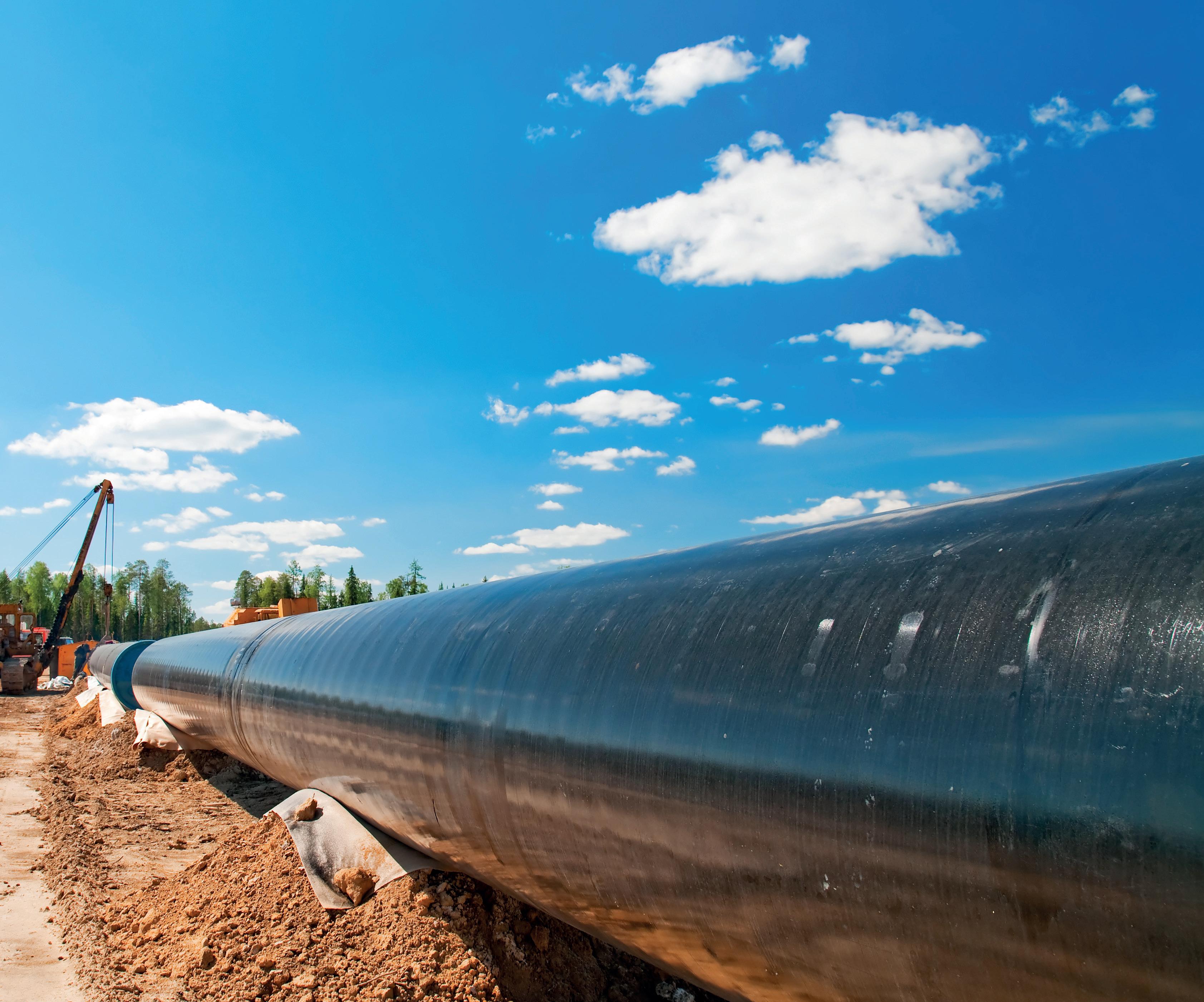
www.worldpipelines.com



























Ian MacLeod, Technical Director, Wood, shares insights from more than three decades of Joint Industry Project (JIP) collaboration in unbonded flexible pipe integrity management.
Unbonded flexible pipe has evolved significantly since its first deployment in its modern form as fuel transfer lines during the 1940s, supporting World War II operations. This early development laid the foundations for subsequent advances that enabled the use of flexible pipe in offshore oil and gas production systems from the 1970s onwards (Figure 1). Today, unbonded flexible pipes are a critical technology enabler for floating production systems and continue to be deployed in increasingly challenging operating environments, including deeper waters, higher pressures, and more aggressive produced fluids.
As with any developing technology, sustained progress relies on systematically learning from operational experience and applying those lessons to mitigate potential design and operational vulnerabilities. The challenges encountered, and ultimately overcome, during the early deployments in the

relatively benign environments of the English Channel are well documented in Ref.1 While many lessons from that era remain relevant, the oil and gas applications of unbonded flexible pipe have generated a far larger and more diverse operational dataset. This collective experience is captured, analysed, and shared across the industry through the Sureflex Joint Industry Project (JIP).
The Sureflex JIP has established itself as the leading collaborative platform for advancing best practice in flexible pipe integrity management. Originating in the 1990s, the project has evolved over several decades, as illustrated in the project timeline (Figure 2), to reflect the expanding use and increasing complexity of flexible pipe systems.
Building on this long-standing foundation, Sureflex continues to deliver data-driven integrity insights to the
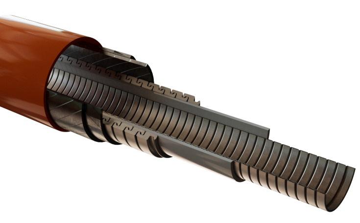
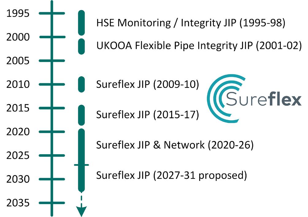
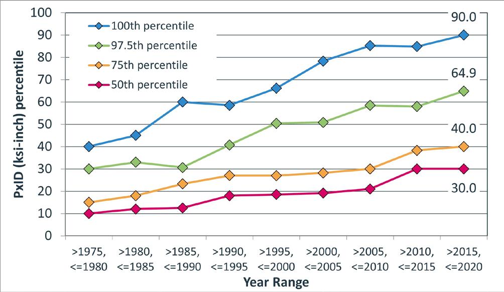
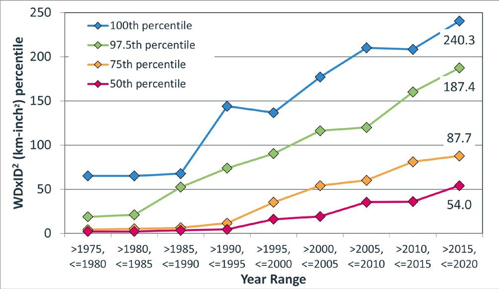
global unbonded flexible pipe community. The project has a clear objective: structured collective learning, not a ‘talking shop’. The project leverages over five decades of operational experience, encompassing 21 000+ km of installed pipe and more than 900 recorded integrity-related events. This extensive dataset enables the identification of industry-wide trends, the early detection of emerging threats and the continuous improvement of integrity management decision-making.
A cornerstone of the Sureflex approach is anonymised data sharing, enabling open collaboration while protecting commercial sensitivities. Through advanced analytics and the development of practical, experience-based guidance, the project supports members in improving safety performance, system reliability and cost efficiency across the lifecycle of flexible pipe assets.
Sureflex also maintains a strong commitment to knowledge dissemination beyond the membership. The project has a long track record of publishing key findings and lessons learned for the wider industry. The most recent major Sureflex report, published at the end of 2023, is available via reference 2 with further updates and republication planned as new data and insights become available in the coming years.2
The overarching objective of the project is the continuous development and optimisation of industry guidance and good practice for the integrity management of unbonded flexible pipe systems. By doing so, the project aims to help both members and the wider industry improve operational integrity and reduce the likelihood of integrity-related incidents.
To achieve this, Sureflex adopts a multi-faceted research approach, centred on the systematic collection, desensitisation and analysis of operational and inspection data relating to:
) Population data, derived from consolidated raw datasets from the supplier members.
) Damage, degradation and failure statistics, including rigorous classification of both the root causes and event severity.
) Integrity management guidance and good practice.
) Operator case studies and emerging threats.
) Inspection, monitoring, repair technologies.
The population database currently encompasses approximately 21 000 km of unbonded flexible pipe, representing approximately 23 000 individual pipe sections, compiled from the collective raw datasets provided by the project’s supplier members. This unique dataset provides unparalleled visibility into long-term operational trends and the evolution of flexible pipe design across multiple decades of industry application.
With data trending back to the 1970s, the progressive development of the flexible pipe industry is clearly illustrated through changes in key design parameters over time. These trends are strongly influenced by the supply and demand dynamics of the industry. As operators increasingly target fields with higher pressures and temperatures, greater water depths, larger bore sizes and more severe environmental conditions,
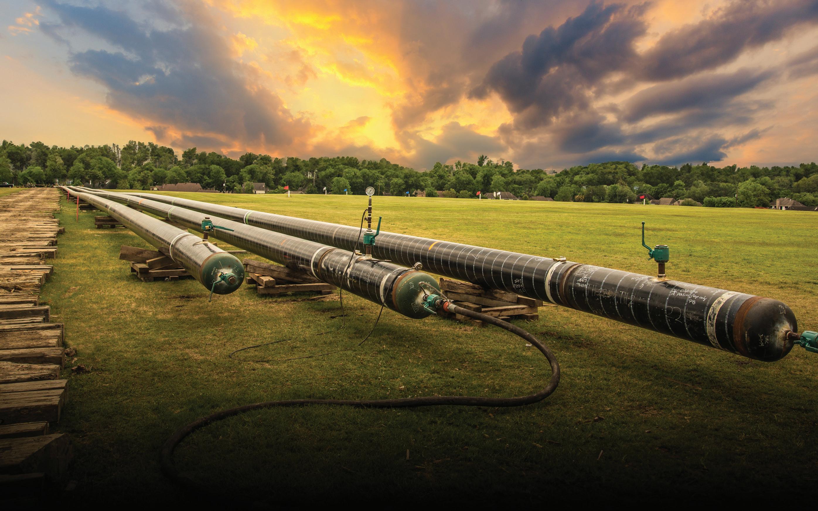
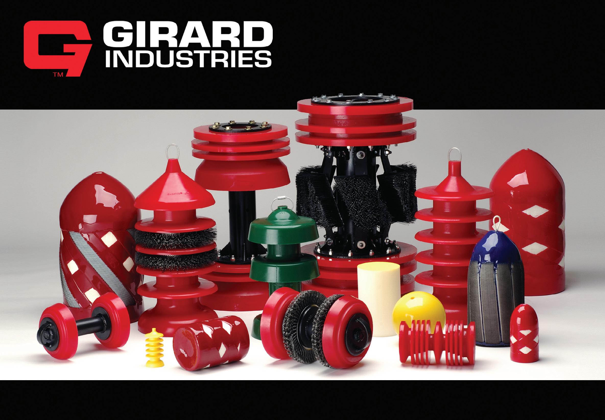

flexible pipe suppliers have continuously optimised designs to address the resulting engineering challenges. As a result, the industry now has operational experience with flexible pipe systems at the following (non-concurrent) upper bounds:
) Design pressure: 15 ksi (1034 bar).
) Design temperature: 130 - 140°C.
) Design water depth: 10 000 ft (approximately 3000 m).
) Pipe inner diameter: 19 in.
The publicly available JIP report presents a comprehensive range of population-based data visualisations, including timelines, trend plots, and scatter charts for all key design and operating parameters.2 More detailed datasets and interactive PowerBI dashboards are available to JIP members. Beyond the numerical trends, the evolution of industry capability is also clearly illustrated in Figures 3 and 4, which show the increase of internal and external pipe capacity percentiles over time.
Figure 3 presents the evolution of internal pipe capacity, defined as the product of design pressure and pipe inner diameter (expressed in ksi-in.). By analysing supplier data in five year time blocks, the figure highlights the increase in the upper bound of deployed experience. In the most recent complete period, the 100th percentile reaches 90 ksi-in., while lower percentiles, including the industry mean (50th percentile), are observed at 30 ksi-in. These percentilebased representations allow operators and designers to directly assess how close a given pipe system is to the limits of industry-wide deployed experience for its supply era, an important consideration in integrity risk assessment and lifecycle management.
Figure 4 applies a similar percentile-based approach to external pressure capacity, using the product of design water depth and the square of pipe diameter as an indicator (expressed in km-in.2). The long-term upward trend is again evident, reflecting continued expansion into deeper waters and the use of larger-diameter flexible pipes. Together, Figures 3 and 4 demonstrate the common progression of internal and external capacity requirements as offshore developments become more technically demanding.
To provide additional context, Table 1 summarises the maximum (100th percentile) internal and external capacity parameters from the most recent dataset period (2015 - 2020), alongside corresponding average (50th percentile) values based on the average pipe inner diameter for the same period. This comparison highlights the gap between the theoretical mean for deployed systems and the leading edge of industry experience, reinforcing the value of population-based benchmarking when evaluating design margins and integrity management strategies.
The JIP dataset includes more than 900 reported damage, degradation and failure events, discretised to a highly granular level within the project’s databases, supported by detailed tables, charts, and member dashboards. While this level of detail enables in-depth analysis of individual mechanisms and contributing factors, overall long-term trends are illustrated in Figure 5, which presents damage and loss-of-containment events across five decades of operational data for the full population of unbonded flexible pipe.
Figure 5 demonstrates a clear reduction in overall incident rates in more recent decades, reflecting improvements in design, qualification, installation and operational practices, and integrity management. However, this high-level view also masks important sub-population behaviours. In particular, certain subsets of flexible pipe, specifically those associated with major rupture events in dynamic riser applications, have exhibited increasing trends in the most recent periods. These observations reinforce the importance of understanding the discrete/detailed trends within the data to avoid the over-reliance on industry-wide averages when assessing specific integrity threats.
When interpreting flexible pipe damage and degradation data, several important points must be recognised:
Not all degradation events result in failure or loss of containment
While every reported event represents a valuable learning opportunity, the most recent Sureflex data show that approximately 80% of all recorded events have not progressed to failure (loss of containment) as illustrated in Figure 6. However, without management intervention some may have evolved into failures over time.
Event severity classification is critical to meaningful risk assessment
Further to the previous point, the project has invested significant efforts in the consistent and accurate classification of event severity and status. This contrasts with some historical datasets outside the project, where degradation, damage and failure have not always been clearly or accurately differentiated. Such inconsistencies can lead to either overly conservative or non-conservative integrity management decisions.
Damage and failure mechanisms are not universally applicable
Many degradation and failure modes are specific to particular pipe designs, materials, or operating conditions. Nevertheless, the high-level trends shown in Figure 5 conservatively combine approximately 40 distinct event causes into a single dataset. While useful for illustrating overall trends,




this reinforces the need for mechanism-specific analysis when applying these datasets to manage the risk to individual systems.
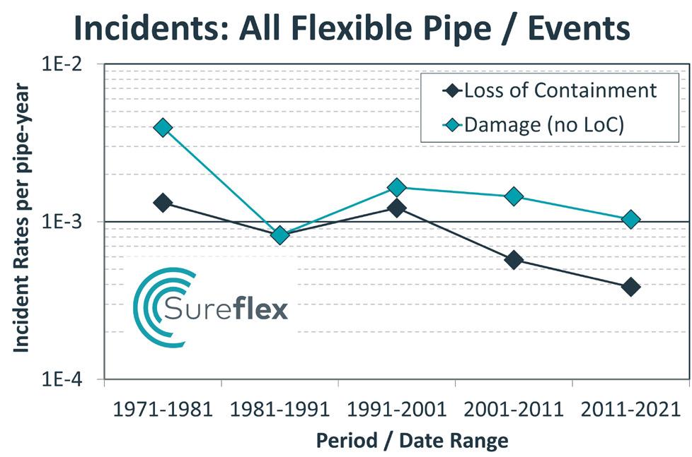
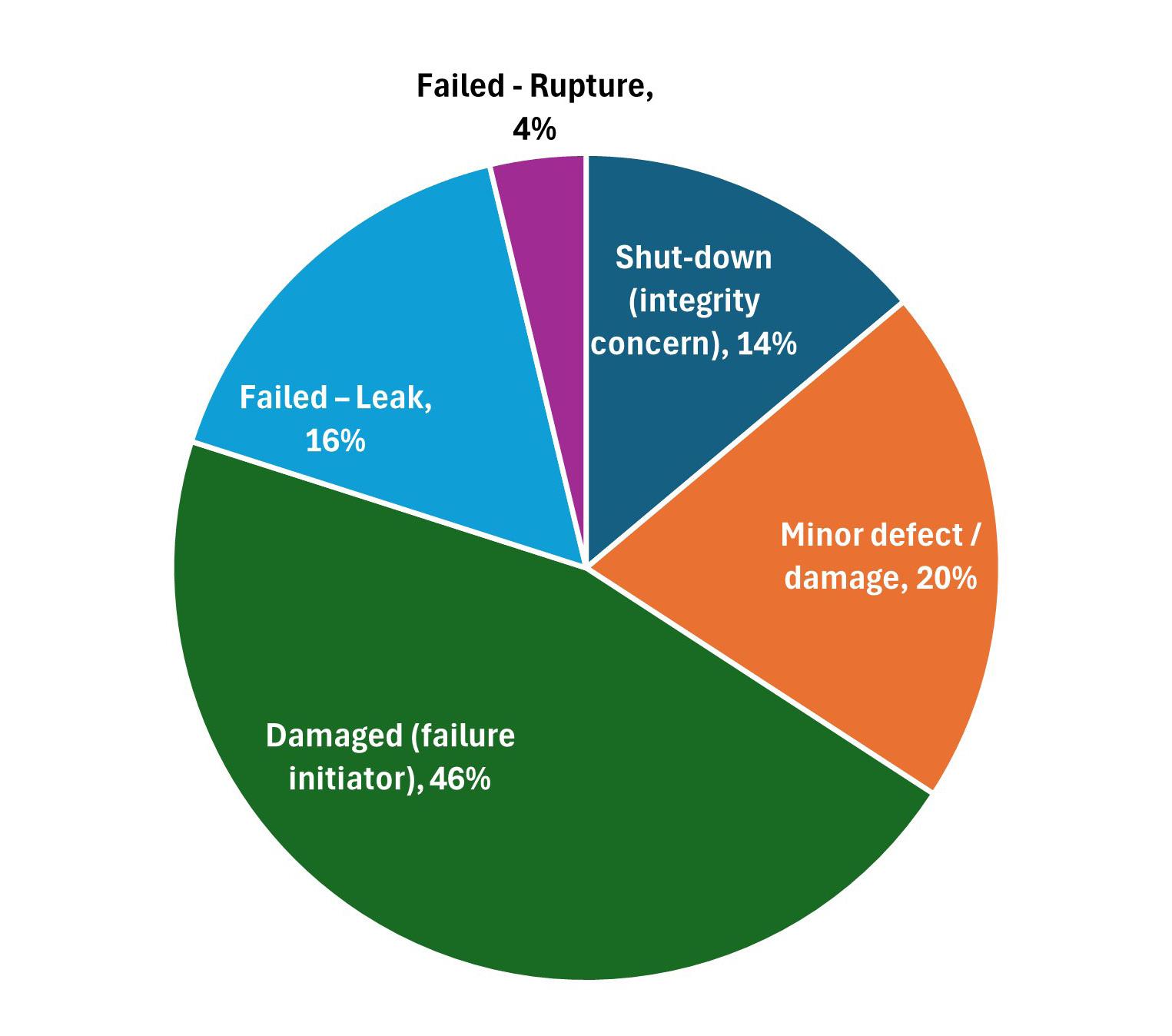
As discussed previously, the past decade has seen an increase in the most significant rupture events associated with riser applications. These events predominantly fall into three emergent degradation mechanisms:
) Fatigue/corrosion-fatigue failures: almost all reported cases involve a significant contributory factor, such as local contact loads, changes in configuration, or discrete damage events, that would not typically be accounted for in conventional fatigue design approaches.
) Stress corrosion cracking of armours due to CO2: this mechanism can lead to rapid failure under specific conditions, notably in the presence of supercritical CO2. While the applicability is limited, it has prompted substantial industry investigation and ongoing R&D activity.
) Corrosion failures due to atmospheric backflow: ingress of atmospheric air/moisture at the topsides riser end fitting, leading to corrosion failures over an extended period, although the mitigation (suitable riser vent configuration) is relatively simple.
The JIP report provides detailed descriptions for all reported rupture events, including the applicability of each event to other pipes and potential mitigations.
Failure causes with ≥5 total cases over all time but that have very limited/isolated cases in recent years may be considered historic, provided that associated operational threats are known and effectively mitigated. Of the 147 total leak events reported over all time with a defined cause, 8 of the defined 22 failure causes meet this criteria, as shown in Table 2. Together, these account for 91 events (61.9%) of all defined leak events to date. Where timeline data exists, only 2.4% of those events have been reported since 2016.
The four most significant historic contributors, and the reasons for their decline, are summarised below:
) Internal pressure sheath, ageing: related to polyamide (PA) lined pipes operating at elevated temperatures, with the majority of failures occurring prior to the end of the 1990s. Since the introduction of API 17TR2 in 2003, failures of this type have been rare.3
) Internal pressure sheath, end fitting pull-out: all but one recorded incident occurred before 2000, and were caused by inadequate crimping of the PVDF internal pressure sheath layers in the end fitting. Updated design and manufacturing methods in the late 1990s are widely considered to mitigate the risk.
) Overbend/pressure armour unlock: most dated incidents occurred between the early 1990s and the mid 2000s, with two thirds occurring during or
prior to installation. Data indicates that in-service threats of overbending/unlock in dynamic risers during storm events is low, indeed, operational and testing experience has shown high resistance to overbending.
) Tensile armours, birdcaging: dominated by deepwater applications with high compression and/or bending at the seabed touchdown point, often combined with degradation of the high-strength tape layers, the designs of which have since been optimised.
It is worth noting that historic mechanisms are intuitively excluded from recent trend analyses (such as the five-decade trends presented in Figure 5). Nevertheless, residual corporate or personal experience of earlier failure events can sometimes shape risk perceptions disproportionately, despite evidence from broader industry datasets.
The project also reinforces the importance of proactive, risk-based integrity management programmes, supported by advances in inspection, monitoring and repair technologies. Vendor workshops share up-to-date industry practices and support users in choosing practical threatmitigation solutions.
The main Sureflex report includes a concise overview of available technologies, alongside detailed technology-specific tables covering indicative technology readiness levels (TRLs), industry uptake and feedback on use, benefits and limitations, procedure elements, industry practices and guidance notes.2
As flexible pipe applications become more complex, collaborative initiatives like Sureflex play a critical role in translating operational experience into practical, data-driven guidance. By uncovering emerging risks and documenting historical lessons, the project supports informed decision-making that protects both assets and personnel.
Led by Wood, the Sureflex JIP brings together contributions from more than 60 member and non-member organisations including operators, suppliers, regulators, certifiers, inspection vendors and specialist contractors. This broad participation underpins the project’s primary objective to assure the safe and reliable performance of unbonded flexible pipe systems throughout their lifecycle.
Looking ahead, Sureflex is preparing for its next five-year phase (2027 - 2031), aiming to further deepen industry collaboration to assure safe operations for ageing and future assets. To share any additional flexible pipe experience to the JIP, request membership information, or for any further information, please reach out to your Wood contact.
1. PLUTO (Pipe-Line Under The Ocean), Adrian Searle, 3rd Edition, 2017.
2. Flexible Pipe Integrity Management Guidance & Good Practice, Sureflex JIP Report, Dec. 2023; https://www.woodgroup.com/sureflexreport-dec2023-flexiblepipeintegrity
3. The Ageing of PA-11 in Flexible Pipes, API Technical Report 17TR2, First Edition, June 2003.
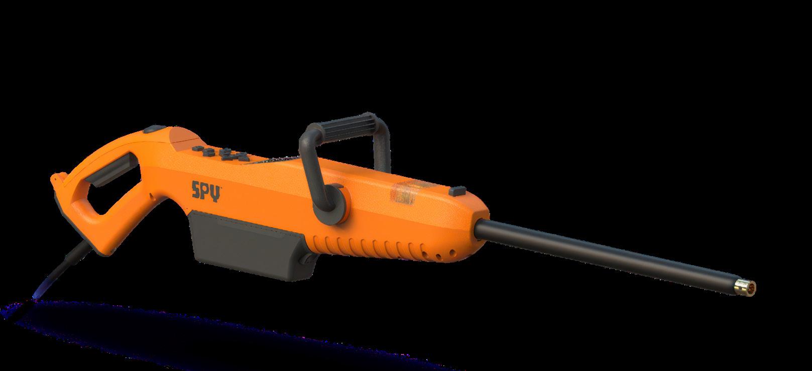
The future of pipeline holiday detection is here. This intelligent, connected detector puts real-time data, precision control, and total jobsite visibility directly in your hands, empowering crews to detect, respond, and perform with unmatched speed and confidence.
» GPS tracking
» Proprietary app & live jobsite data
» Audio/visual holiday detection
» Lithium-Iron batteries
» Ergonomic safety switch
» Bright LED display

» Ground contact indicator
» Backward-compatible accessories
» Real-time voltage control
» Holiday count tracking
» Jobsite data recording
» Remote calibration
Victor Ng, Principal Engineer, and David Baxter, Hydrogen Pipeline Materials Specialist, Kent, discuss a structured engineering approach to assessing the technical, safety, integrity, and commercial feasibility of repurposing offshore oil and gas pipelines for new services.
The opportunity to repurpose an offshore pipeline arises when its original design purpose no longer aligns with the evolving production profile and characteristics of an oil and gas field. The typical cost of a new 30 in. pipeline is US$3.32 million/km, with three to four years schedule expected from concept to operation. Repurposing can reduce cost, schedule, and environmental impact. A repurposing assessment’s goal is to confirm whether changes can achieve project goals whilst meeting pipeline limits.
However, repurposing comes with challenges and considerations that must be carefully addressed to ensure its success. There is currently limited standardised approach for repurposing, and the considerations are often project specific. Therefore, a successful repurposing heavily relies on expert engineering judgment across a range of disciplines.
A new approach to pipeline repurposing
At Kent, we have decades of experience in pipeline engineering. Our approach to successful pipeline repurposing (Figure 1), is staged to align with typical project phases, addressing high risk factors early stage and engage with the
stakeholders and related disciplines to inform key factors for feasibility. Factors with significant impact are informed early to steer decision making. As the assessment progresses into details, the risks and uncertainties will reduce and required actions become better defined. This collaborative approach ensures that a balanced outcome, between the pipeline and its role within the wider facilities.
Establishing the project case
Step one is to determine whether the existing pipeline together with the proposed facility arrangement, can meet the basic operational requirements of the new service. This involves confirming that key technical parameters, i.e. fluid characteristics, pressure, temperature, and flowrate are in a range where repurposing can be considered feasible, and that the overall solution is commercially viable before progressing into detailed engineering.
Pipeline and facilities design and arrangement
The design and arrangement options for pipeline facilities are assessed to determine whether repurposing an existing pipeline is a viable option.
Facilities potentially impacted by the repurposing include:
) Pipeline entry and reception facilities, such as piping, pig launcher/receiver, structural capacity/footprint and any fluid conditioning, compression or pumping facilities required.
) Mid-line reconfiguration and tie-in works required for partial reuse of existing pipeline.
) A high-level identification of safety systems required and feasibility of such system within the proposed facility arrangement.
Some considerations during this assessment include:
) Availability of a mothballed pipeline or timing and opportunity for an existing pipeline to be taken out of service and made available for repurposing in alignment with the project schedule.
) High level integrity of pipeline and feasibility to extend life.
) The differences in facility design required to accommodate repurposing, compared to installing a new pipeline. The resultant difference in capital and operational expenditures.
) Project-specific operational risks and opportunities, including schedule impacts, constructability constraints, regulatory/permitting considerations, and long-term operational flexibility.
The feasibility repurposing is highly dependent on the pipeline’s flow and mechanical capacities, material suitability and safety implications. Where unsuitable, these factors involve significant
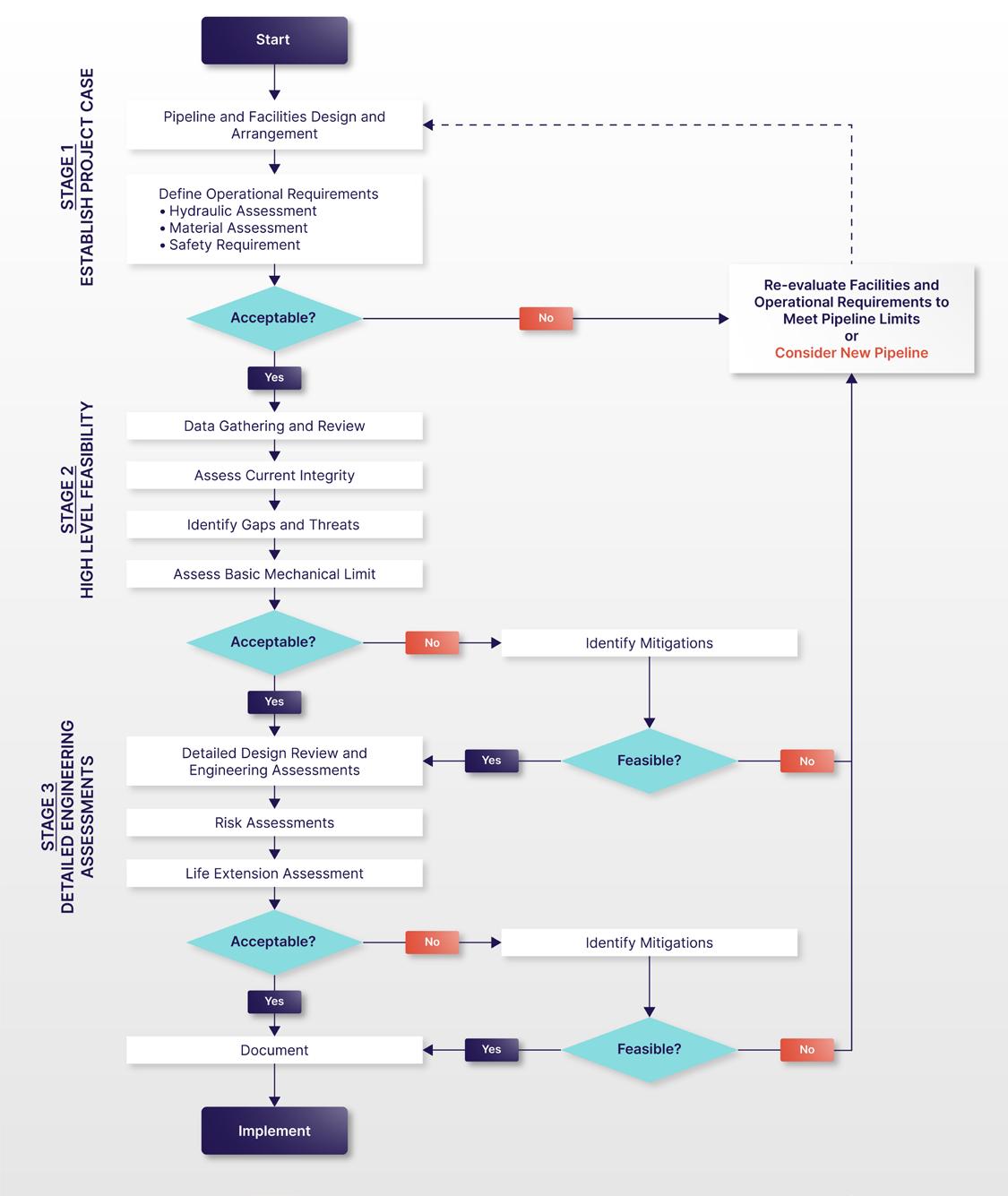
change and cost to accommodate the limits of existing pipeline. Hence, a reasonable alternative is to opt for a new pipeline.
Below assessments are expected to define the operational requirements of the pipeline and acts as a preliminary basis for pipeline repurposing.
Hydraulic assessment: confirm the key service conditions (fluid phase, pressure, thermal profile) at the target flow conditions and assess requirements of pumping/compression and reception facilities.
Generally, if a pipeline is not sufficiently sized for flow, repurposing becomes unfeasible. Assessments may need to consider a range of scenarios to account for uncertainties of supply and demand from interconnected pipeline, process, and storage systems.
Material assessment: evaluate material compatibility for new service and preliminarily identify fluid conditioning facilities (e.g. contaminant control, inhibition) to enable service conversion.
If risk of material failure is high due to compatibility issues, repurposing becomes unfeasible.
Safety requirements: evaluate safety implications from change to a more hazardous fluid impacting design code, safety zoning, safety and environmental impact, safety systems (detection and control instrumentation, isolation valves), protection requirements, and equipment rating.
Safety requirements can significantly impact the outcomes of engineering assessments, and these risks should be identified early.
Stage two confirm the high-level technical feasibility of the pipeline repurposing. This stage of the assessment compile known information of the pipeline design, its current integrity, determine new mechanical limits, and identify gaps and threats that help to further define where detailed engineering assessments are needed.
Good quality and reliable data are required to enable an effective assessment. Key pipeline data are collated for review to identify potential gaps. These data generally consist of:
Pipeline design data should be sufficiently detailed and accurate to allow rerun of design assessments against the repurposing conditions.
Operational and management system records
Covers the historical management of the pipeline and informs the current threats and expected degradation on the pipeline.
Inspection and maintenance records
Covers the findings from inspections and maintenance activities. Inspection records provide an insight to degradation trends on the pipeline. Maintenance activities
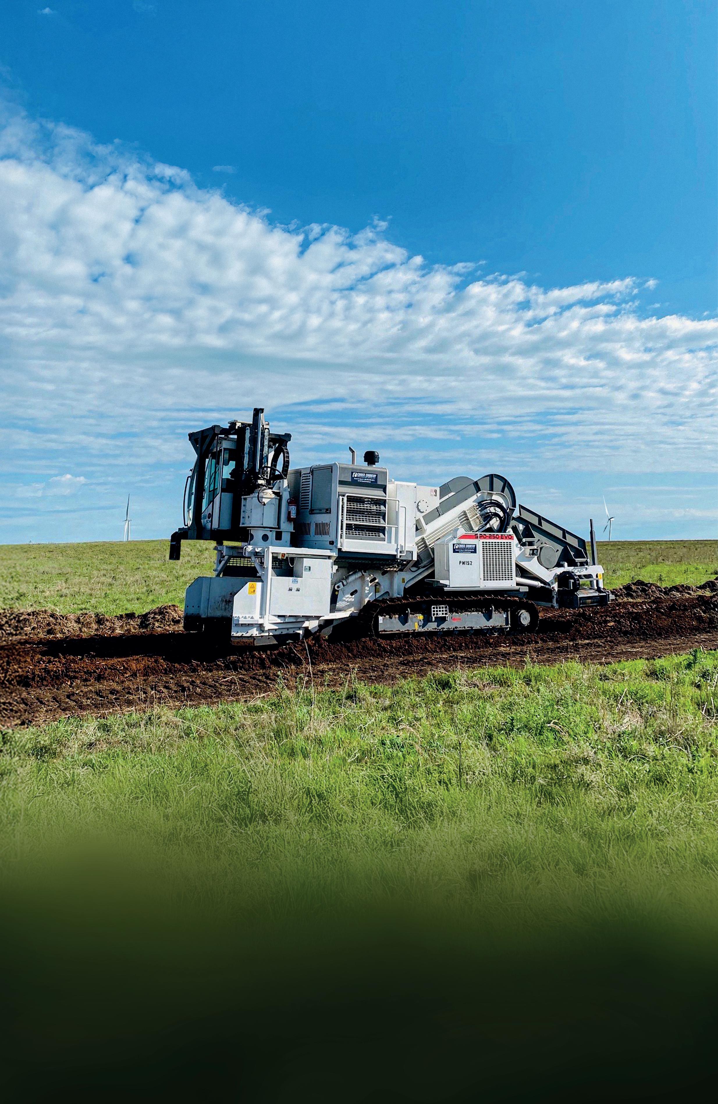

will restore the pipeline’s functionality or stop active degradation.
Any additional engineering work performed and controls in place to address pipeline defects, failures, repair, or modification to its original design.
The data collation exercise will seek to verify the availability and accuracy of key information for the assessment. The extent and criticality of data gaps may prompt mitigation, such as physical data gathering or inspection, or applying engineering judgement in defining bounding assumptions or sensitivities during assessments.
The pipeline should be in a condition acceptable for repurposing. However, existing inspection activities, anomaly criteria and fitness for service conclusions are only relevant only for the current operation. Exiting integrity acceptance criteria (e.g. corrosion, free span, embedment, fluid impurities, cyclic loading etc.) are commonly impacted by the change. The integrity assessment should highlight the impacted threats and fitness for service/design assessments that need to be reassessed.
For example, a currently acceptable progressive loss of concrete weight coating due to aging can be of greater significance when converting from oil to gas service as pipeline weight is significantly reduced leading to potential loss of on bottom stability. The inspected condition shall be assessed against the acceptance criteria in the new gas service.
A qualitative identification of threats and gaps between the original pipeline design basis and the repurposing requirements is then performed. These gaps typically arise from differences between the original design assumptions and the proposed repurposing conditions.
) Incomplete data essential for assessments.
) Different code and regulatory requirements respective to fluid service.
) New operating above the current limits, original limits invalidated, new limits to be established
) Impact to future integrity management needs and to extend the pipeline life.
) Specific considerations of the project.
The gap and threat analysis identifies a list of engineering assessments needed. A repurposing basis should define the applicable design codes to be used and the proposed engineering methods to address them. The assessments are prioritised based on its impact to overall feasibility. High priority assessments generally deal with threats which adversely affect mechanical limits of the overall pipeline, involving unfeasible technical challenge or remediation cost. Low priority threats are those that can be remediated locally and feasibly managed during operations.
A reassessment of the basic mechanical limits (allowable design and operating pressure and temperature) shall be undertaken to confirm adequate mechanical capacity for the proposed service. This assessment should be performed accounting for any gaps, threats and existing defects alongside the new operating requirements.
The assessment should generally start with a screeninglevel evaluation, progressing into details if needed to improve acceptability margins.
In some instances, a change in fluid type can have a significant impact on mechanical limits. For example, hydrogen or H2S service will significantly impact the risk of fracture or fatigue and make the pipeline less tolerance of mechanical damage (dents, gouges). For dense phase CO2, the risk of ductile running fracture requires existing pipeline with a high material toughness.
Stage 3 of the assessment commences once there is sufficient confidence that the pipeline is feasible for repurposing. By this stage, the pipeline’s history, requirements and new arrangement should be sufficiently mature to allow the development of a formal assessment basis. A risk assessment shall be performed to document and consolidate all identified pipeline risks. This stage focuses on detailed evaluation and quantification of all areas affected by repurposing, with the objective of confirming, through engineering design review and relevant assessments, that the pipeline can safely and reliably operate in its new service.
The nature of engineering assessments for an existing pipeline differs to that of a new pipeline design. In these assessments, engineers apply the current physical conditions and backcalculates for pipeline limits and determines additional actions needed to reach the acceptance criteria. Below are some examples.
) Determine new corrosion control requirements (e.g. contaminant control, corrosion inhibitor, pigging).
) Determine new acceptability limits (e.g. free span, seabed embedment).
) Specify requalification requirements (e.g. hydrotest, valve test).
) Specify mitigations to restore pipeline integrity (e.g. repair/replace pipe sections, supports, coating, anodes).
Repurposing can result in a significant change to the pipeline risk profile. A pipeline risk assessment shall therefore be performed to assess potential impact from the change. The risk assessment formalises the identification and evaluation of all relevant threats and gaps, and confirms the adequacy and effectiveness of the proposed engineering activities in addressing these risks. The risk assessment may also be extended to capture risks to the overall project, including technical, cost, and schedule risks.


Cyber governance: What pipeline boards must know
A conversation about board-level cyber responsibility in oil and gas. Featuring Brittany Bacon, Partner in Global Privacy and Cybersecurity at Hunton Andrews Kurth LLP.
From the regulatory aftermath of the Colonial Pipeline attack to SEC disclosure rules, fiduciary duties, vendor risk, cyber insurance disputes, and evidence preservation during incident response: this conversation dives into what ‘reasonable’ really means in the eyes of regulators and courts.
As digitalisation accelerates and operational technology remains vulnerable, cybersecurity is a board-level responsibility. Brittany outlines the practical questions that directors should be asking.
Greene Tweed
Rockwell Automation
Black & Veatch


Listen and subscribe here
Risk assessments may be qualitative, semi-quantitative or quantitative. In some cases, there may be legislative requirement to perform a quantitative risk assessment. A risk assessment should identify new threats or conditions that may influence the failure probability and consider potential changes to the failure consequence. Change of service to hydrogen or CO2 for instance can lead to significant change to failure consequence and require for specific modelling to characterise risk.
The outputs of the risk assessment subsequently inform the project decision, further mitigations and forms a basis to the future pipeline management strategy.
Repurposing of a pipeline is generally involves operating beyond its original design life. A life extension assessment is recommended to confirm that the pipeline will remain suitable for the new service life.
This should clarify the long-term implications resulted from change in pipeline threats and inform on likely mitigations and associated costs needed for pipeline maintenance.
The life extension assessment process is guided by various standards and guidance (E.G. ISO 12747, NORSOK Y 002, OEUK and UKOPA) and involves similar steps and elements as repurposing, albeit with particular focused on time-dependent degradation. Kent has published a separate
June 9-11, 2026 | Calgary, Canada
article ‘Unlocking Pipeline Potential: Extending Service Life for Greater Value and Sustainability’ covering this topic.
A repurposing basis should be prepared at the start of the process and updated through the assessment stages as conditions become defined. This should include all original design information, new operation and project requirements and engineering assessment method statements.
The assessment concludes by highlighting key residual risks that require further mitigation and linking them to the development of project scope, cost, and schedule estimation, and constructability evaluations. By closing out the assessment in this manner, Kent ensures that technical feasibility and economic considerations are captured and provides a clear implementation pathway for the project.
Kent is a global integrated energy services company with over 100 years of history. We leverage decades of experience and groundbreaking solutions across conventional energy, low carbon, and renewables. We operate across the full asset lifecycle, from early advisory, feasibility, and FEED through to EPC delivery, construction management, commissioning, late-life asset management and decommissioning. Our recent repurposing studies span conventional conversions (oil- to-gas, gas-to-oil and hydrocarbon-to-produced water) as well as emerging services such as natural gas to CO2, H2 and H2-blended gas.


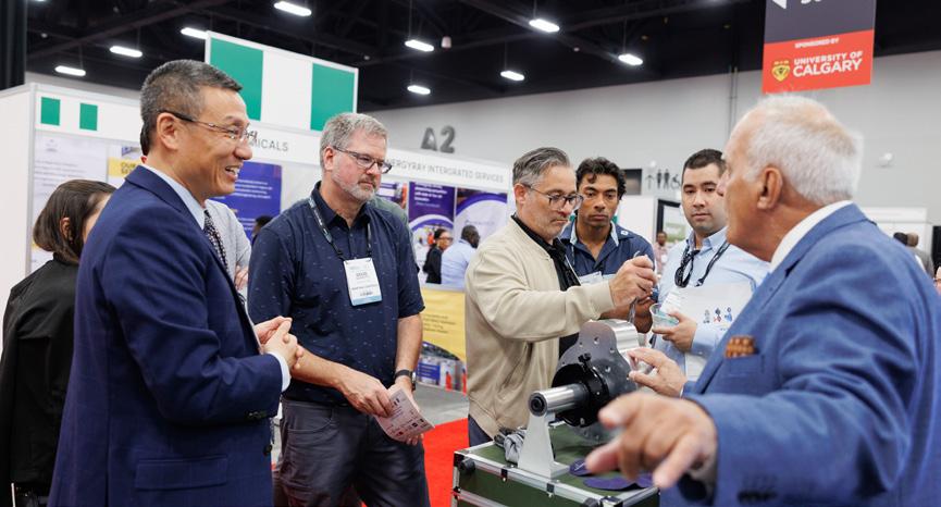

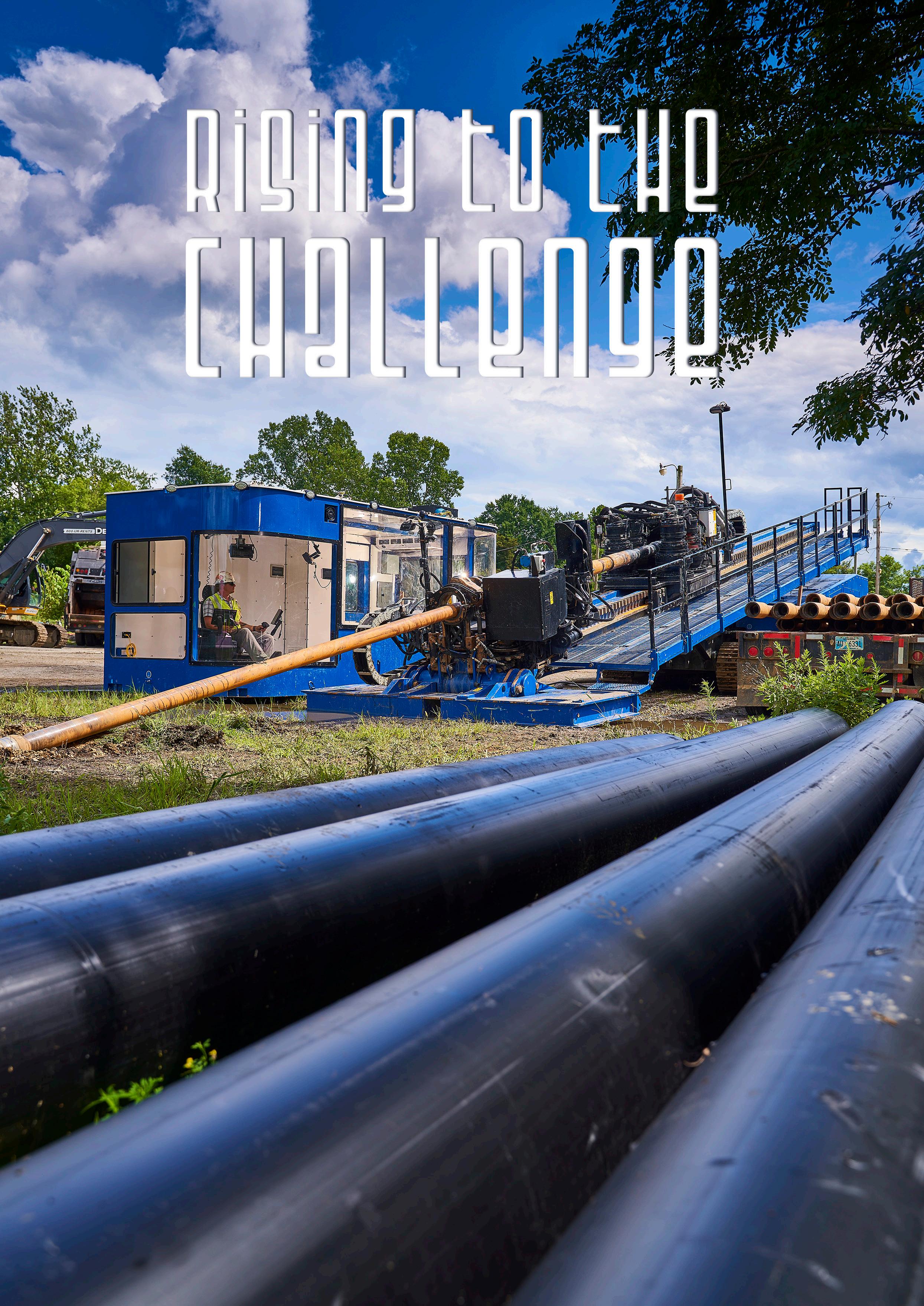
Richard Levings, Project Manager, American Augers, examines how the global horizontal directional drilling (HDD) market is preparing for its biggest decade yet.
The horizontal directional drilling (HDD) industry, particularly in the maxi-rig segment, is at a pivotal turning point. As projects are increasingly popping up all over the world, contractors are busier than
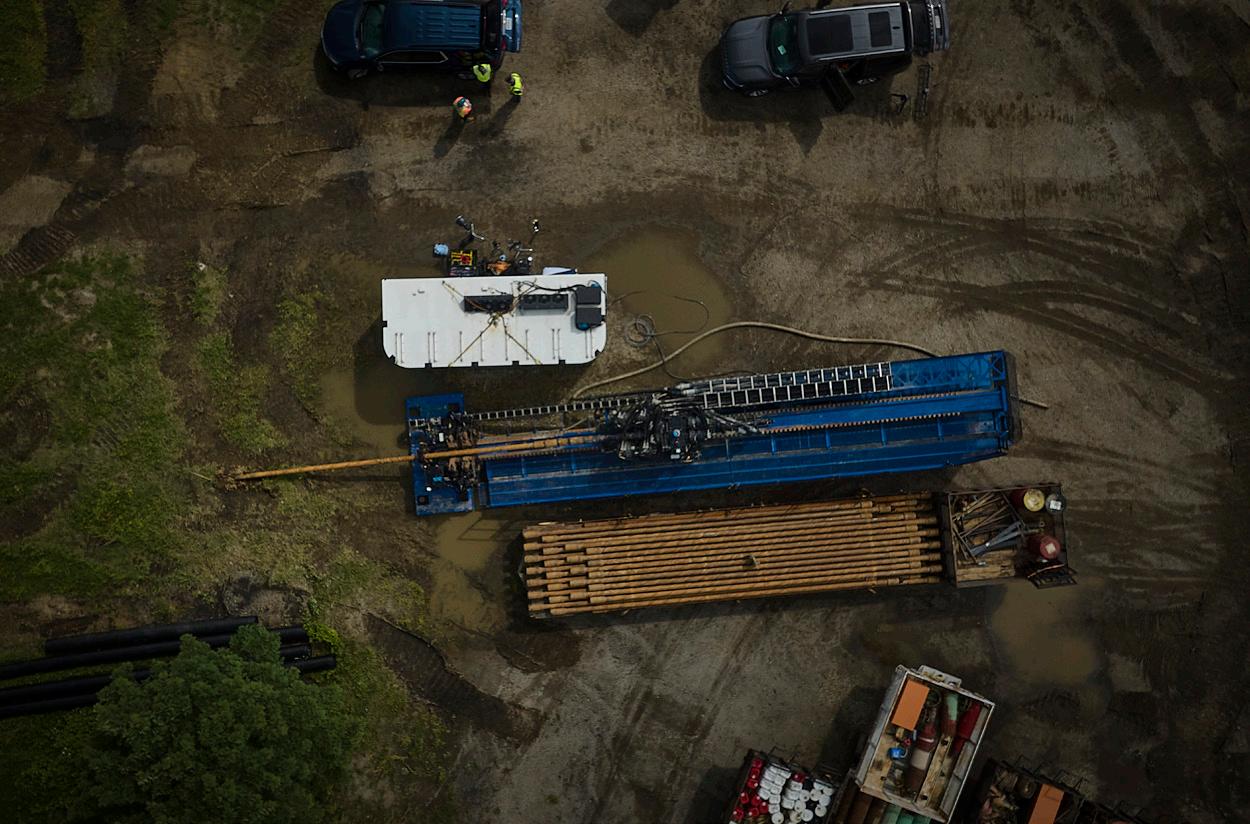
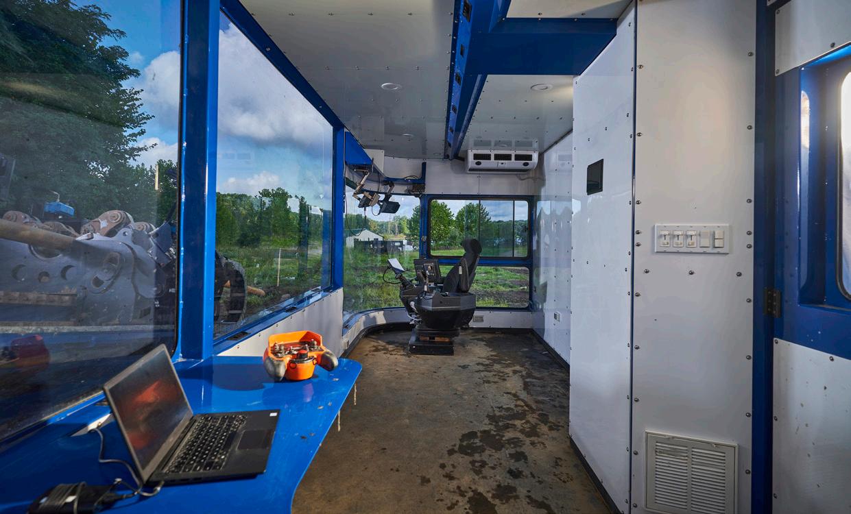
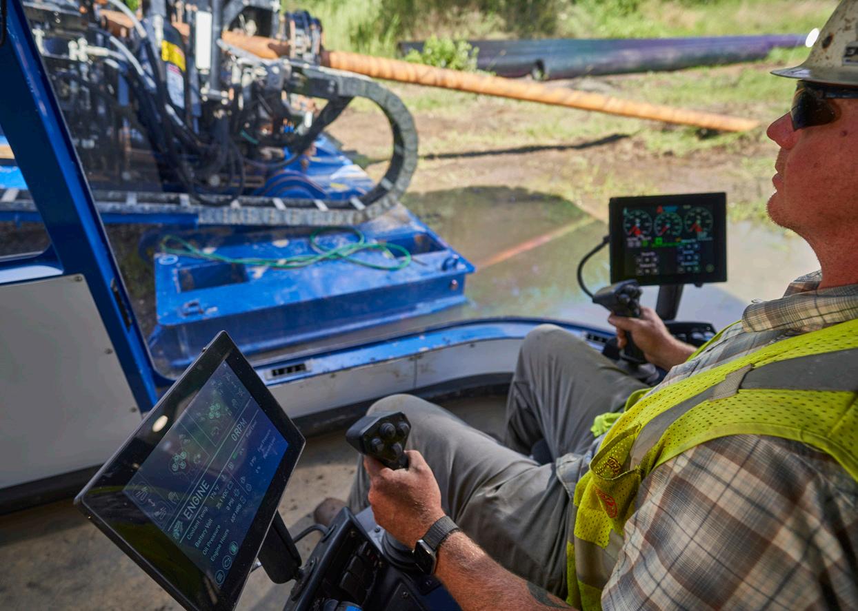
ever. However, they are having to deal with the fact that old rigs and support gear that built yesterday’s network aren’t going to meet tomorrow’s demands. The business is changing fast, and to keep pace, contractors are scrambling to trade in aging fleets for new machines that deliver bigger bores, deeper crossings, and far less downtime on the jobsite.
Just a few short years ago, the market was steady; everyone had their favourite rig, and jobs ran on reliable patterns. Now, things have shifted into high gear. Federal funding is flowing into broadband, water, utility, and energy projects, while private investment continues at a steady pace. This means contractors are now seeing longer, deeper bores show up in project specs, with tighter schedules and higher stakes. Today, even the most skilled crews rely on advanced equipment to keep pace. Contractors are counting on equipment that can handle what’s coming.
Anyone walking around a busy jobsite today can spot the problem. There are plenty of hard-working rigs, but you’ll hear stories of breakdowns, parts shortages, temporary fixes and crews spending more time troubleshooting than drilling.
Owners and engineers want to see stateof-the-art equipment, proven reliability and detailed contingency plans beforetooling hits the dirt. That’s why the contractors are partnering with manufacturers who have dedicated their time and resources to refining their rigs and rolling out models built for today’s headaches. Newer models are from-theground-up designs with more torque, higher pullback ratings, and the kind of operational setup and teardown simplicity that makes life easier for crews.
Manufacturers are incorporating advanced controls and real-time diagnostics, turning troubleshooting from a jobsite emergency into a manageable process. The experience is totally different for site managers. Issues pop up on-screen, predictive alerts let maintenance teams handle problems before they become disasters, and on-the-fly adjustments keep drilling on track even if conditions change unexpectedly.
One topic that comes up constantly in conversations with contractors is drilling fluid. On maxi rig projects, it’s not just a byproduct;
27-30 APRIL 2026, BERLIN
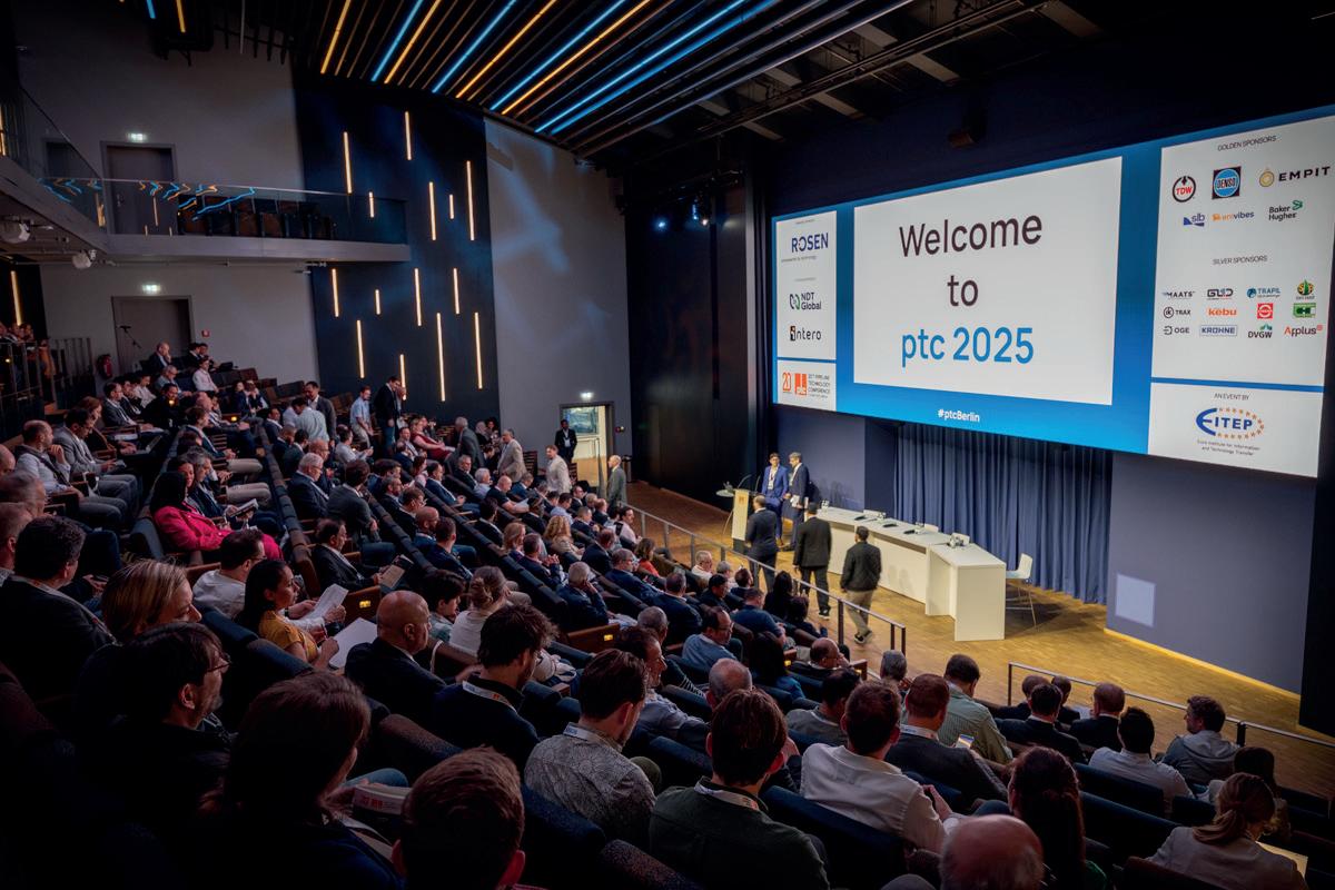
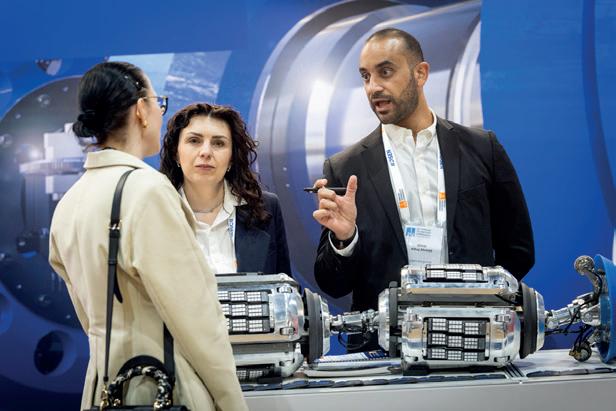


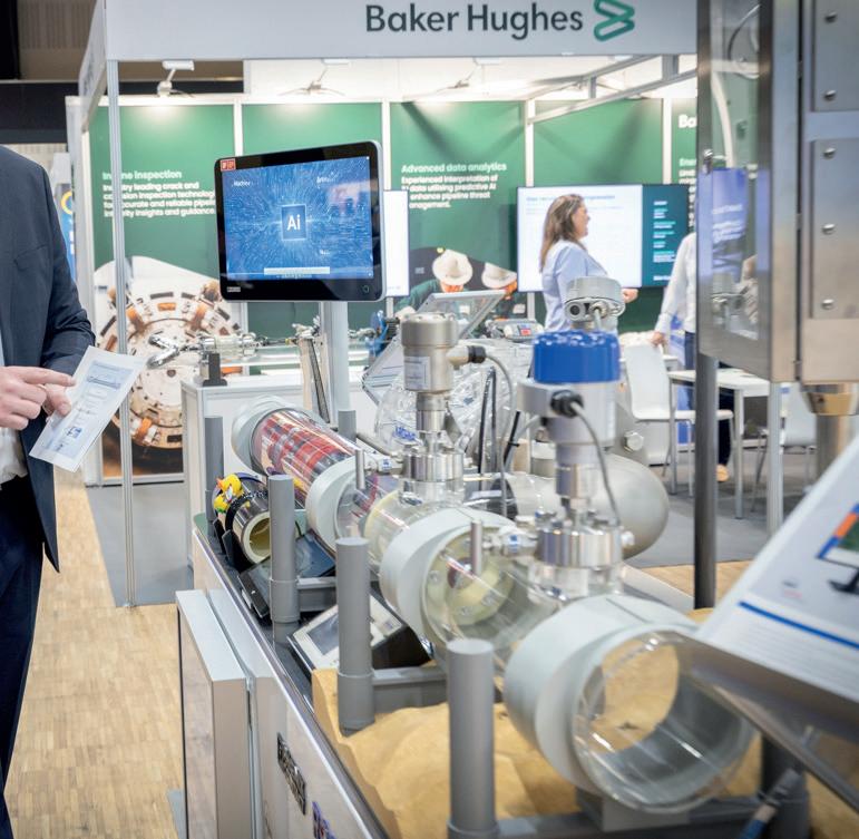

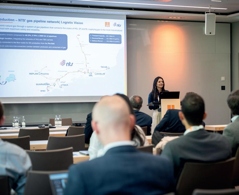
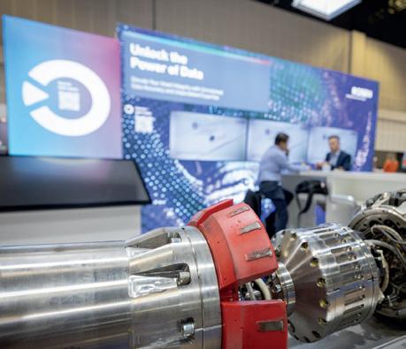





it’s often one of the industry’s most persistent challenges. The larger the bore, the more gallons of fluid are required and on multi-thousand-ft runs, contractors often manage hundreds of thousands of gallons of used mud that needs somewhere to go.
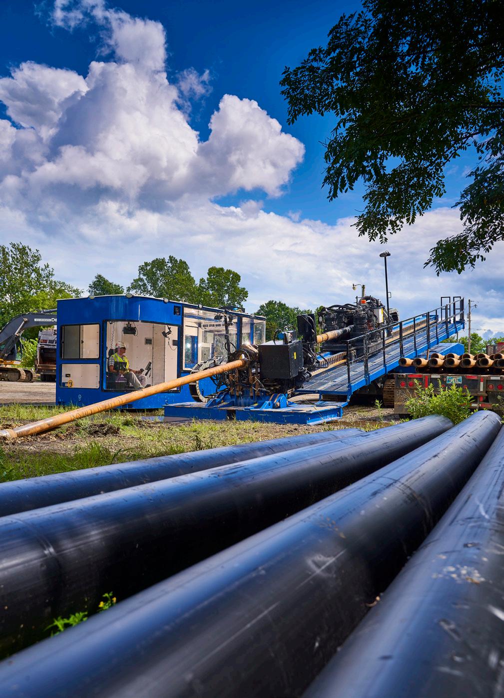
Disposal is costly, time-consuming, and heavily regulated. Contractors working across multiple states often find that every jurisdiction has its own rules, leaving them juggling a patchwork of permits and disposal fees. In some cases, the cost of hauling and dumping mud can rival labour expenses, eating into margins and making bidding more complicated.
That’s where a strong fluid cleaning system makes a real difference. By recycling fluids on-site, contractors can reduce the number of loads they need to dispose of and minimise both trucking costs and environmental impact. Cleaned mud means fewer fresh deliveries of water and additives, keeping projects moving while conserving resources. Less hauling also means fewer delays waiting for tanks to clear before drilling continues.
In a market where workloads are rising and regulations are tightening, contractors who have reliable cleaning systems in place are finding they can stay more competitive. Over time, that smarter approach can make the difference between a crew that’s constantly stretched thin and one that consistently finishes complex crossings on budget and on schedule.
During slower market periods, manufacturers like American Augers didn’t wait for demand to rebound. They committed to investing in resources for research and development (R&D), field-testing, and direct collaborations with HDD professionals. That time and investment show up in equipment that’s ready for the new challenges, including rigs and support systems built with today’s feedback and tomorrow’s technologies.
The OEM/contractor partnership isn’t just about selling machines. Rather, manufacturers work directly with field crews, designers, and project managers to understand what each job needs. This approach pays off in proven reliability, improved ergonomics and features directly shaped by field feedback. Contractors who invest in these machines find themselves with better training resources, clearer documentation, and a direct line for troubleshooting and advice when issues do arise.
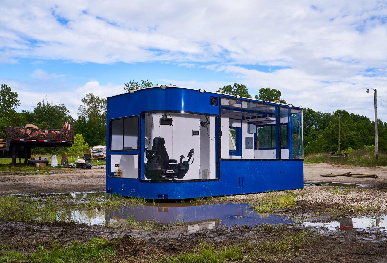
The story isn’t just about keeping up; it’s about setting the standard. Modern fleets allow contractors to promise reliability, safety, and transparency that older outfits simply can’t match. In an industry defined by precision and uptime, these advantages translate directly into a competitive edge. They deliver better results with fewer surprises, negotiate tough schedules, and pivot quickly as opportunities or challenges emerge.
Modern rigs and fluid systems are paving the way for what project owners
now expect. It’s not just about hardware. It’s about a way of working that keeps projects moving, builds trust, and keeps clients coming back to contractors, job after job.
Training and teams: bringing crews up to speed
Of course, new machines are only as good as the people running them. That’s why manufacturers are upping their game on training and support. American Augers ensures contractors can adopt new technology seamlessly, offering on-site support from local Ditch Witch dealership technicians, factory assistance, digital resources, and partnerships with technical colleges. This hands-on stance helps crew members build confidence to operate rigs and fluid systems safely and efficiently, no matter their experience level.
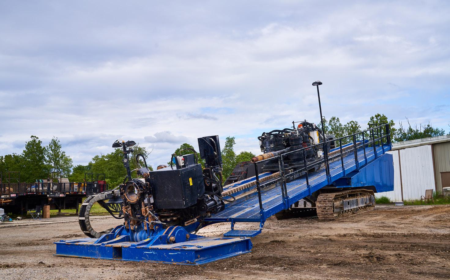
and maximises output. Knowledge is shared, mistakes are limited, and teams trust the equipment to do its job.
On jobsites where new rigs are backed up by smart training, the transition can almost be seamless. Operators pick diagnostic tools, learn how to work with automated systems, and get used to a pace that minimises stress
Next-level opportunity: ready for the next wave
This industry isn’t slowing down. With so much infrastructure work on the horizon, and competition

tightening as larger and more complex projects hit the market, contractors know they can’t afford to wait. Fleet renewal isn’t just a checkbox; it’s a business necessity. Owners want modern machinery, regulators require compliance, and successful bidding increasingly depends on proof that contractors can deliver under pressure.
The push to replace aging rigs and invest in advanced support systems is becoming the new baseline. Contractors who jump in early find themselves in the sweet spot. They can field demands for longer crossings and bigger bores, adjust quickly when project specs change and operate with less downtime and risk.
This is positioning for growth. As the market expands, those ready with modern fleets are the ones who land multi-year contracts, set the standard for jobsite efficiency and build reputations as partners who always bring reliability and expertise.
What’s exciting about this moment in HDD is the way contractors, manufacturers, and clients are working together. Fleet renewal is part of a collaborative push to raise standards, innovate and build the infrastructure that communities need. Manufacturers like American Augers are at the table, not just selling equipment but listening, learning and delivering solutions that move the industry forward.
For contractors, the challenge isn’t just technical, it’s cultural. Making the decision to upgrade is about embracing a new way of working, one centered on planning, teamwork, and a shared commitment to excellence. It’s about building for the long-term, knowing that the market rewards those willing to invest in progress.
The HDD industry is accelerating into a new era, one defined by modern equipment, smart fluid management, and data-driven precision. Contractors who invest now aren’t just keeping up; they’re positioning themselves as leaders in reliability and performance.
Manufacturers are delivering the tools and support needed, helping contractors transform uncertainty into operational strength. New rigs and fluid recycling systems are redefining what’s possible in the field, making sure downtime, regulatory headaches and missed deadlines become a thing of the past.
For those willing to act, the reward isn’t just a smoother job today. It’s the promise of more wins tomorrow, a reputation built on operational excellence and a front-row seat as the next chapter of HDD takes shape. In this business, the future belongs to those who build it, and right now, there’s never been a better time to trade in the old and embrace what comes next.