®
Volume 24 Number 2 - February 2024
REPLACE WOOD LAGGING & CONCRETE COATING ®
Build a safer pipeline with engineered pipeline lagging Engineered products used separately or top to bottom for total protection, ensuring you get superior support at every angle. Learn more on page 15 and visit us at AMPP 2024, Booth #2127. 1.866.PIPESAK (747.3725) ®
Industry leading impact protection, withstanding 60lbs (27kg) boulders dropped from 10 feet Absorb impact with a unique peak & valley design Lightweight & easy to handle Compatible with CP systems Reduced labor needs Speed up your project Eliminate the need to import select fill No machinery required
43
25
51
CONTENTS WORLD PIPELINES | VOLUME 24 | NUMBER 02 | FEBRUARY 2024 03. Editor's comment 05. Pipeline news
INLINE INSPECTION Q&A 25. With T.D. Williamson, ROSEN Group, ENTEGRA, Onstream Pipeline Inspection, Intero Integrity Services and Quest Integrity
With updates on the Dakota Access oil pipeline, Iraq-Turkey pipeline and Trans Mountain project, as well as offshore contract news.
KEYNOTE: EUROPE AND THE UK 08. Europe: the old and the new
Q A
Inline inspection
Gordon Cope, Contributing Editor, considers the current state of the European energy sector, weighing in on pipeline sabotage, interconnector projects, LNG capacity, and the hydrogen economy.
World Pipelines quizzes some inline inspection experts on defect detection, ILI data accuracy, and the latest developments in pipeline integrity.
with... Callie Lamb, Integrity Engineer I, T.D. Williamson Callie Lamb has worked for T.D. Williamson for 10 years. Starting as a Data Analyst, she has held various roles, including Client T.D. Williamson: One of the first inline inspection tools, KALIPER® from TDW, circa 1979. Representative, Team Lead, Modelling Analyst, and Technical Advisor II. With a Bachelor of Science in Data Management/Data Analytics, she holds several certifications, including Level III MFL and DEF, and a Nanodegree in Data Analytics. She currently supports Integrity Engineering work by performing integrity assessments, threat management, modelling and statistical analysis.
Thomas Beuker, Head of Group Business Line Advanced Pipeline Diagnostics, ROSEN Group Thomas Beuker is responsible for the worldwide provision of ROSEN’s crack inspection services, as well as ILI services to determine T.D. Williamson: Newer tools place emphasis on employing the material properties and the stress and strain status of a pipeline. He started with the R&D department at ROSEN in Germany.multiple His sensors to detect interacting threats, exemplified by the MDS™ Platform from TDW. expertise lies in data analysis, finite element modelling and in the development of new sensor technologies.
Michael Rapp, Head of Group Business Line Proficient Pipeline Diagnostics, ROSEN Group
How do inline inspection technologies help maintain Michael Rapp focuses mainly on metal loss and geometry services. He joined the ROSEN Group 12 years ago to lead the implementation pipeline integrity? of product and service development processes at the ROSEN Technology & Research Centre in Lingen (Ems), Germany. Callie Lamb, T.D. Williamson: In the late 1960s, the initial inline Markus Ginten, Head of Group Business Line Challenging Pipeline Diagnostics, ROSEN Group inspection (ILI) tools were developed, and ongoing efforts Markus is responsible for the challenging pipeline inspection business globally. His academic background is in Civil Engineering and Business Administration. In the industry, Markus has obtained more than 17 years of experience as Engineer, Product Manager andhave Areabeen dedicated to their development, persistently striving to advance pipeline integrity. Examining individual Sales Manager in the UK, Germany and the US. or isolated threats, such as metal loss (e.g. corrosion) and Corey Richards, Head of Business Line – Field Products & Services, ROSEN Group in Canada geometric irregularities (e.g. dents), has become a standard Corey Richards oversees ROSEN’s Field Products and Services as well as Challenging Pipeline Diagnostics in the Canadian region. Within element within the integrity management programmes of the Challenging Pipeline Diagnostics domain, Corey has focused on developing solutions for complex piping systems in the Canada, Oceana and Asia Pacific regions. Recently, he has expanded his responsibilities to include the optimisation of pipeline throughputpipeline operators. In the case of piggable pipelines, ILI serves as a fundamental method for detecting and sizing defects efficiencies. throughout the entire pipeline length. Options other than ILI, such as hydrotesting or certain forms of direct assessment, Niek Bruijnesteijn, Director of Engineering Solutions, Intero Integrity Services mayinincur high costs and consume significant time. Therefore, Niek Bruijnesteijn has spent his entire professional life in the NDT of pipelines, tanks and heaters. He joined A.Hak Industrial Services ILI represents the most effective approach to verify the 2002 (now Intero Integrity Services) and specialised in inline inspection and integrity management of challenging pipelines. Nowadays, immediate integrity and, when employed through multiple within Intero Integrity Services, Niek is responsible for global solutions engineering, leading a global team of highly experienced subject runs, enables insights into both growth and future integrity. matter experts to find or create inspection solutions for the most challenging pipelines, heaters and storage tanks. Mark Olson, ENTEGRA: While reliably delivering the energy Mark Olson, Chief Executive Officer, ENTEGRA needs Mark Olson is currently the CEO (and one of the founders) of ENTEGRA. Previously, Mark was one of the founders of CPIG and was a of their local community, pipeline operators are required Pipeline Integrity Engineer for several major US liquid pipeline operators. He is a passionate advocate for knowing your pipeline and for to protect the environment and public against ‘all threats’. Examples of integrity threats are: corrosion, cracks, making better every pipeline he works on. gouges, terrorism, pipe movement, erosion, etc. The pipeline operators are responsible for identifying any possible threats Dave Latto, General Manager, Onstream Pipeline Inspection on since their systems and aligning those threats with the most Prior to joining Onstream Pipeline Inspection, a member of MISTRAS in 2020, Dave Latto has been involved in the pipeline industry assessment techniques, whether an inline application 1991 with a focus on inline inspection beginning in 2002. In his current role his responsibilities include managing the Onstream USeffective base while ensuring continued growth and development within the US market with the goal of safe, efficient and accurate execution or of over-the-ditch. inline inspection projects. In general, inline applications allow the operator to assess the pipeline for the relevant integrity threat in a cost-effective manner and without disruption to the normal pipeline Drew Casey, Service Line Director – Pipeline, Quest Integrity operations. The data tends to be quantitative and allows for With over 15 years’ experience in pipeline integrity and operations management, Drew leads and develops the pipeline service line team management of change and for the application of advanced to ensure the delivery of high-quality services that meet the needs of Quest Integrity and their customers. engineering processes and methods.
Gordon Cope, Contributing Editor, considers the current state of the European energy sector, weighing in on pipeline sabotage, interconnector projects, LNG capacity, and the hydrogen economy.
EUROPE: THE OLD AND THE NEW E
urope’s energy sector is in the cross-hairs; geopolitical risk is at its highest level in decades, the shift to a low-carbon economy could cost trillions of Euros, and nobody knows if they will freeze in the dark next winter. While challenges abound, they present great opportunities for the midstream sector. The destructive effects of the Ukraine war continue to spill over into the pipeline sector. In September 2022, saboteurs attacked the Nord Stream pipeline network that runs under the Baltic Sea from Russia to Germany. The 100 billion m3 system was instantly rendered inoperable when explosives breached the steel at several points. There are no lack of culprits, including the US, Russia and Ukraine but, so
8
Michael Rapp, ROSEN: In recent years, the industry has identified the value of additional ILI services to determine the material properties and stress/strain condition along the pipeline, which are not considered anomalies but a crucial part of the equation to calculate the robustness of a given pipeline, especially in the presence of the mentioned anomalies. At ROSEN, we have broadened our offering, particularly with regard to ILI for material properties determination and stress/strain assessment. Without a doubt, the data obtained with an ILI tool is the most detailed information a pipeline operator can gain from their valuable assets. However, all this often comes at a price that is much higher than the cost of the inspection: a reduction of the flow rate to ensure optimal ILI data quality. For this reason, we at ROSEN continue to develop technologies that minimise the operational impact of an ILI. Our automatic adaptive speed control unit (SCU) is an excellent example of this. Depending on the velocity of the medium and the ILI tool, it constantly adapts the medium flow through the ILI tool in such a way that the ILI tool velocity is kept constant for optimal ILI data quality. Starting at pipeline diameters of 12 in., the ROSEN SCU allows for medium velocities of up to 12 m/sec. (40 ft/sec.) during an ILI inspection – while still collecting high-quality ILI data. Considering the loss of transport income due to a potential reduction in flow velocity during an ILI, this represents OPEX cost savings that could easily be much higher than the additional cost of an automatically adaptive speed control unit (SCU) on an ILI tool. In other words: the SCU is paying off big time. Dave Latto, Onstream Pipeline Inspection: ILI companies are a part of the overall pipeline integrity puzzle. By collecting ultrahigh resolution data sets for metal loss, geometry, strain and pipe centreline, pipeline owners can have an understanding of their current pipeline condition and exact location. When that information is combined with other pertinent data such as soil type, coatings, product, pressure cycles and numerous other factors, operators can paint a more accurate picture of the overall pipeline condition and complete preventative maintenance before issues arise and worsen. The complete data puzzle is often managed within a larger database or Integrity Management Software, which has additional tools to assist operators with early identification of potential problems while maintaining compliance. Niek Bruijnesteijn, Intero Integrity Services: ILI is often considered to be the only proper way of reliably determining a pipeline’s integrity, but that’s a false assumption. In fact, an inspection in itself yields limited information. Only if combined with other datasets can the inspection results be considered worthwhile and actually contribute to the ability to oversee the pipeline’s integrity. Datasets like hydrotests, coating surveys, cathodic protection measurements and soil condition studies are very important when contributing to the ILI results, as they provide a comprehensive overview of the pipeline’s condition and allow accurate decision making to ensure the pipeline’s integrity going forward.
25 26 World Pipelines / FEBRUARY 2024
PAGE 9
08
PAGE
25
CORROSION PREVENTION 39. A helping hand with surface preparation Drs. JF Doddema, CEO, Monti Werkzeuge GmbH, Germany.
43. A clean sweep for welding
CONSTRUCTION 15. Progress in pipe protection
Tony Hufford, Category Manager – Metal Fabrication, Weiler Abrasives.
Meghan Connors, President, PipeSak, Canada.
David D’Ambrosio and Richard Norsworthy, Polyguard Products, USA.
MEASUREMENT 21. Sealing the breach
PIPELINE MACHINERY FOCUS 51. With Bobcat, Develon and McElroy
47. Coating challenges in cold environments
Benjamin Fuentes, Thermo Fisher Scientific, USA.
®
ON THIS MONTH'S COVER
Volume 24 Number 2 - February 2024
Reader enquiries [www.worldpipelines.com]
ISSN 1472-7390
CBP019982
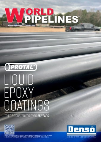
Winn & Coales International Ltd has specialised in the manufacture and supply of corrosion prevention and sealing products for over 90 years. The well-known brands of Denso and Premier offer cost-effective, long-term corrosion prevention solutions, including their Pro-tal™ range of high build, fast cure liquid epoxy coatings. The front cover application features Protal 650 CTR™ (Coal Tar Replacement) on a project in Houston, Texas (USA).
Member of ABC Audit Bureau of Circulations Copyright© Palladian Publications Ltd 2024. All rights reserved. No part of this publication may be reproduced, stored in a retrieval system, or transmitted in any form or by any means, electronic, mechanical, photocopying, recording or otherwise, without the prior permission of the copyright owner. All views expressed in this journal are those of the respective contributors and are not necessarily the opinions of the publisher, neither do the publishers endorse any of the claims made in the articles or the advertisements. Printed in the UK.
WCI WP Cover_Feb 2024.indd 1
16/01/2024 16:05
Self Healing Corrosion Prevention & Sealant Technology
EDITOR’S COMMENT
T
CONTACT INFORMATION MANAGING EDITOR James Little
james.little@palladianpublications.com
EDITORIAL ASSISTANT Isabel Stagg
isabel.stagg@palladianpublications.com
SALES DIRECTOR Rod Hardy
rod.hardy@palladianpublications.com
hose pipeliners who keep an eye on the upstream sector will have noticed that last year’s merger mania is continuing into 2024. In January, Chesapeake Energy and Southern Energy announced their merger, for nearly US$12 billion. 2023 saw a bumper crop of M&A activity upstream, the biggest of which was ExxonMobil’s US$59.5 billion acquisition of Pioneer Natural Resources, which created the world’s first ‘megamajor’ (and was the largest upstream deal since 2015). Other deals in 2023 included Chevron’s US$60 billion acquisition of Hess Corp; Occidental Petroleum’s purchase of CrownRock; Harbour Energy’s US$11.2 billion acquisition of Wintershall Dea; and Tokyo Gas purchasing Haynesville Shale gas
SALES MANAGER Chris Lethbridge
SENIOR EDITOR Elizabeth Corner
SALES EXECUTIVE Daniel Farr
producer Rockcliff Energy for US$2.7 billion. Wood Mackenzie’s What to Look for in 2024 upstream series outlines some key themes for the upstream sector in the coming year. Continued consolidation is expected: “For deals to work, they need to demonstrate improved operational, financial and, for some deals, emissions performance,” said Fraser McKay, Head of Upstream Analysis for Wood Mackenzie. “Some buyers may follow ExxonMobil’s playbook with Pioneer and look to bring unique data, technology, and processes to a basin. Others will be marriages of convenience. But not all deals will work, and it will remain hard for smaller international Independents to prove tangible synergies between disparate portfolios than their larger more diversified brethren.”1 In January, ratings agency Morningstar DBRS gave its view on the global pipeline and midstream industry in 2024, declaring the outlook ‘neutral’. “We expect oil and gas prices to soften in 2024; however, we expect excess supply to primarily drive the softening. Consequently, we expect asset utilisation in the sector to remain strong as rising energy exports drive up oil and gas production in North America. Additional tailwinds include consolidation among oil and gas producers, which should improve counterparty risk profiles, stabilising interest rates and moderating inflation.”2 Morningstar DBRS’s point about consolidation among producers is key here. Upstream oil and gas sector M&A deals are, more often than not, strategic tools for various end points: diversification, to counteract the effect of declining reserves, and to secure future resources. Likewise, we’ve seen midstream mergers happening so that companies can gain access to strategic pipeline networks, gathering lines, processing assets, storage, and other important infrastructure. Sometimes it’s about a move into the Permian, or an acquisition of CO2 pipelines, or for exposure to overseas markets. Forbes states that: “Mergers and acquisitions of other pipeline companies [is] the surest way by far to grow earnings and dividends, at least for the next few years”.3 In the midstream sector recently, we have seen a host of activity: Magellan Midstream Partners merged with ONEOK Inc.; Phillips66 bought DCP Midstream; Energy Transfer acquired Lotus Midstream; Kinder Morgan closed on its purchase of NextEra Energy Partners; Pembina Pipeline acquired some of Enbridge’s JV interests; and of course Sunoco is set to buy NuStar Energy for US$7.3 billion. Midstream companies seek out deals like this to “gain the scale, scope and synergies they think they will need to succeed in an increasingly competitive industry.”4 Analysts are split on how to view this glut of M&A activity: does it show “that there is significant industry confidence that oil and gas demand is set to remain healthy for some time” (Raj Shekhar, GlobalData)?5 Or is it an acknowledgement that the energy transition is here and, “rather than spending lots of money on exploration or developing new projects, companies are pursuing a more risk-averse strategy [of] buying into existing production” and assets (Mike Coffin, Carbon Tracker)?5
chris.lethbridge@palladianpublications.com
daniel.farr@palladianpublications.com
PRODUCTION DESIGNER Kate Wilkerson
kate.wilkerson@palladianpublications.com
EVENTS MANAGER Louise Cameron
louise.cameron@palladianpublications.com
DIGITAL EVENTS COORDINATOR Merili Jurivete merili.jurivete@palladianpublications.com
DIGITAL CONTENT ASSISTANT Kristian Ilasko kristian.ilasko@palladianpublications.com
DIGITAL ADMINISTRATOR Nicole Harman-Smith nicole.harman-smith@palladianpublications.com
ADMINISTRATION MANAGER Laura White laura.white@palladianpublications.com
Palladian Publications Ltd, 15 South Street, Farnham, Surrey, GU9 7QU, UK Tel: +44 (0) 1252 718 999 Website: www.worldpipelines.com Email: enquiries@worldpipelines.com Annual subscription £60 UK including postage/£75 overseas (postage airmail). Special two year discounted rate: £96 UK including postage/£120 overseas (postage airmail). Claims for non receipt of issues must be made within three months of publication of the issue or they will not be honoured without charge. Applicable only to USA & Canada: World Pipelines (ISSN No: 1472-7390, USPS No: 020-988) is published monthly by Palladian Publications Ltd, GBR and distributed in the USA by Asendia USA, 701C Ashland Avenue, Folcroft, PA 19032. Periodicals postage paid at Philadelphia, PA & additional mailing offices. POSTMASTER: send address changes to World Pipelines, 701C Ashland Avenue, Folcroft, PA 19032.
elizabeth.corner@palladianpublications.com
1. 2. 3. 4. 5.
https://www.woodmac.com/news/opinion/upstream-oil-gas-2024-outlook https://www.dbrs.morningstar.com/research/427218/global-pipeline-and-midstream-industry-outlook-2024-energy-exports-todrive-growth https://www.forbes.com/sites/greatspeculations/2023/05/22/magellan-midstream-is-merging-and-others-will-follow https://rbnenergy.com/lets-work-together-midstream-companies-combining-to-gain-scale-fill-in-asset-gaps https://www.globaldata.com/newsletter/details/exclusive-sky-high-oil-and-gas-m-a-divides-energy-transition-analysts_134320
The experts you can trust CRC Evans’ market-leading welding and coating services, technologies and equipment ensures efficient, on-time delivery of your global onshore and offshore energy projects.
crcevans.com Americas
enquiries@crce.com Europe
Middle East
Africa
@crcevansglobal Asia Pacific
WORLD NEWS
Energy Transfer: Dakota Access oil pipe won’t shut after environmental study Energy Transfer does not expect the US Army Corps of Engineers to shut down the Dakota Access oil pipeline (DAPL) after a long-pending environmental review of a section that runs under a lake and is opposed by nearby Native American tribes, Executive Chair Kelcy Warren said on Tuesday (reports Reuters, 23 January). A US court in 2022 ordered the federal government to undertake a more intensive environmental impact statement (EIS) of the 1100 mile (1800 km) long crude pipeline’s route, the latest saga in a lengthy court battle between the tribes and pipeline operator Energy Transfer. In a draft statement in September, the US Army Corps of Engineers did not select a preferred alternative of five options,
including abandoning or rerouting the pipeline around Lake Oahe, a federally protected reservoir. It will make its selection only after public and agency comments were received and a final version prepared, the draft report said. “We’re not affected by (the EIS study),” Warren said, while speaking at the Argus Americas Crude Summit in Houston. “They’re certainly not going to shut us down.” A final EIS will be complete in late 2024, Steven Wolf, a spokesperson for the Army Corps, told Reuters on Tuesday. The pipeline, which began operating in 2016, can transport up to 750 000 bpd, or 60%, of crude from North Dakota, the third largest US oil producing state to Illinois.
Sunoco to buy NuStar Energy for US$7.3 billion Sunoco is to acquire fuels storage and pipeline operator NuStar Energy in a deal valued at about US$7.3 billion including debt, as it tries to diversify its core business beyond distribution of motor fuels. Reuters reports that the equity portion of the deal comes up to US$2.99 billion, and NuStar’s shareholders stand to receive 0.400 of a Sunoco share for each NuStar unit they hold, valuing Sunoco’s shares at US$23.78. That represents a premium of 31.9% to NuStar’s last closing price. “Having the fuel distribution business helps keep your midstream assets full, and often these assets provide a foundation for additional growth and supply synergies,” Sunoco executives said in a call. The deal, which has been approved by both the boards, will
give Sunoco access to NuStar’s transportation and storage facilities, including a portfolio of about 9500 miles of pipeline and 63 terminals. NuStar would provide exposure to crude terminals and pipelines, refined products terminals and pipelines, a large ammonia pipeline, and exposure to the West Coast and Midwest, Fitch analyst Michael Ruggirello said. Dallas-based Sunoco is an affiliate of US pipeline operator Energy Transfer, which is controlled by billionaire Kelcy Warren. Shares of Sunoco were down 5.1%, while shares of NuStar were up nearly 17%. The companies have flagged cost savings of US$150 million by the third year following closing of the deal, expected in 2Q24.
Trans Mountain Corp. granted pipeline variance The Canada Energy Regulator has approved a request for a pipeline variance from the company building the Trans Mountain pipeline. The regulator said on Friday 12 January, 2024, it will release the reasons for its decision in the coming weeks. At an oral hearing in Calgary, the Crown corporation behind the project urged the regulator to make a decision quickly on whether the company will be allowed to change the size, thickness and coating of a 2.3 km stretch of pipe between the
communities of Hope and Chilliwack, B.C. Just hours after the hearing wrapped up, the CER announced it had approved Trans Mountain’s variance application with conditions. The reasons for the decision will be released in the coming weeks, the statement said. Trans Mountain Corp. is racing against the clock to complete the expansion project, which will boost the capacity of Canada’s only oil pipeline to the West Coast to 890 000 bpd from 300 000 bpd currently.
Disagreements over payments holds up Iraq-Turkey oil pipeline restart Turkey shut down the pipeline in March 2023, after an arbitration court ordered it to pay Iraq US$1.5 billion (Tl 45.23 billion) in compensation. Iraqi Prime Minister Mohammed Shia Al-Sudani has said that disagreements over payments with producers are further delaying the reopening of a key pipeline, reported Bloomberg. The closure of the northern-Iraq-to-Turkey pipeline has resulted in a monthly revenue loss of almost US$1 billion (ID 1.31 trillion) for the Kurdistan Regional Government (KRG) and companies in the region. It has also kept about half a million bpd of crude oil from entering the global market. During an interview at the World Economic Forum in Davos, Al-Sudani said that the oil companies “have an issue
with the cost of producing barrels”. The Association of the Petroleum Industry of Kurdistan, representing the companies, did not respond to requests for comment, reported the media outlet. Turkey shut down the pipeline in March 2023 following an order from an arbitration court asking it to pay US$1.5 billion to Iraq in compensation for transporting oil without Baghdad’s approval. However, Ankara claimed the closure was due to undertaking of necessary repair works after two massive earthquakes in February 2023. In October last year, Turkey announced that the pipeline was ready for operations, and left the decision to Iraq to resume flows. FEBRUARY 2024 / World Pipelines
5
CONTRACT NEWS EVENTS DIARY 12 - 16 February 2024 PPIM 2024
Houston, USA www.ppimconference.com/exhibition
13 - 15 February 2024
AMI Pipeline Coating Vienna, Austria www.ami-events.com
3 - 7 March 2024
AMPP Annual Conference + Expo 2024 New Orleans, USA www.ampp.org
8 - 11 April 2024
Pipeline Technology Conference (ptc) 2024 Berlin, Germany https://www.pipeline-conference.com
15 - 19 April 2024
TUBE Düsseldorf 2024 Düsseldorf, Germany www.tube-tradefair.com
6 - 9 May 2024
Offshore Technology Conference (OTC) 2024 Houston, USA https://2024.otcnet.org
11 - 13 June 2024
Global Energy Show 2024 Calgary, Canada www.globalenergyshow.com
26 - 29 August 2024 ONS 2024
Stavanger, Norway www.ons.no
9 - 13 September 2024 IPLOCA convention Sorrento, Italy www.iploca.com/events/annual-convention
6 World Pipelines / FEBRUARY 2024
IK Subsea to deliver pipeline repair equipment for China contract
McDermott wins Malaysia CCS project
Norwegian company IK Subsea, and PAG Subsea Technology (Guangzhou), have signed a contract with COOEC Subsea Technology, one of the largest EPCI contractors for offshore oil and gas industry in the Asia Pacific region. As part of the contract, IK Subsea will design and deliver a series of DNV-approved high pressure pipeline diverless repair clamps (both structural and sealing) for COOEC’s National Oil & Gas Pipeline Emergency Repair Base in Shenzhen, China. This project is pivotal, ensuring rapid and efficient pipeline repair operations in the South China Sea and East China Sea, according to IK Subsea. The delivery will take place throughout 2024, IK Subsea, an IK Group company, confirmed.
McDermott has been awarded a contract from Malaysia Marine and Heavy Engineering (MMHE) for the Kasawari Carbon Capture and Storage (CCS) project, located offshore Sarawak in East Malaysia. McDermott will perform transportation and the structural installation of a 138 km (85 miles) pipeline section, a 15 000 t CCS platform jacket, and bridge connecting to the existing central processing platform. The installation activities will be performed by one of McDermott’s heavy lift and pipelay vessels. Operated by PETRONAS Carigali, the Kasawari CCS project is expected to reduce carbon dioxide volume emitted via flaring by 3.3 million t of CO2e per year.
Huisman awarded contract from Subsea7 Huisman has been awarded a contract from Subsea7 for the delivery of a 500 t Offshore Mast Crane. The full electric crane will be installed on one of Subsea7’s pipelay vessels and will be deployed for deepwater installations. The 500 t Offshore Mast Crane will be equipped with a state-of-the-art passive and active heave compensation system on the main hoist to counteract the vessel’s heave motion when landing a product onto the seabed. Huisman has upgraded its heave compensation system with a variety of new control modes to extend the operational window. The crane will be built in Huisman’s production facility in Schiedam, the Netherlands. David Roodenburg, CEO of Huisman says: “We are delighted to announce this contract of our valued client, Subsea7. Our pursuit of continuous improvement has led to the upgrade of our Offshore Mast Crane to an impressive 500 t, showcasing our dedication to innovation and client satisfaction.” Huisman Mast Cranes have been used within the industry for over 30 years and have become a standard in the design and construction of heavy lift cranes. The company boasts a track record of nearly 50 Offshore Mast Cranes successfully deployed for offshore construction and ultra-deepwater operations, reaching depths of up to 5000 m.
ON OUR WEBSITE
• Rystad Energy: What’s in
store for energy in 2024 • Nigeria investigates Shell
pipeline leak • PRISMA introduces Mid-
Term Tenders through AggregateEU • CRC-Evans inspection
business sold to strategic buyer • FERC greenlights pipeline
projects
• Australian court lets Santos
build pipeline for Barossa gas project Follow us on LinkedIn to read more about the articles linkedin.com/showcase/worldpipelines
THE FINAL COUNTDOWN! March 3-7, 2024 | Ernest N. Morial Convention Center | New Orleans, Louisiana
It’s time to get AMPP’d! AMPP Annual Conference + Expo is heading to the U.S. Gulf Coast!
Experience the ultimate gathering of materials protection professionals
50+
600+ hours
peer-reviewed sessions
600+ hours of
15
industry and technology tracks
programming
Scan for more information ace.ampp.org
60+ countries
represented
300,000 square feet of exhibit space
Gordon Cope, Contributing Editor, considers the current state of the European energy sector, weighing in on pipeline sabotage, interconnector projects, LNG capacity, and the hydrogen economy.
EUROPE: THE OLD 8
E
urope’s energy sector is in the cross-hairs; geopolitical risk is at its highest level in decades, the shift to a low-carbon economy could cost trillions of Euros, and nobody knows if they will freeze in the dark next winter. While challenges abound, they present great opportunities for the midstream sector. The destructive effects of the Ukraine war continue to spill over into the pipeline sector. In September 2022, saboteurs attacked the Nord Stream pipeline network that runs under the Baltic Sea from Russia to Germany. The 100 billion m3 system was instantly rendered inoperable when explosives breached the steel at several points. There are no lack of culprits, including the US, Russia and Ukraine but, so
AND THE NEW 9
far, no irrefutable proof of guilt has been found, nor have operators instigated any efforts to repair the pipeline. A second incident is just as worrying. In October 2023, the Balticconnector pipeline between Estonia and Finland was breached by an errant anchor. The 77 km line, which entered service in 2020, was designed to connect Finland to the European gas network. Finnish authorities are focusing on a Chinese commercial vessel, the NewNew Polar Bear, which was in the vicinity at the time of the strike and appeared to have lost one of its anchors. While intentional sabotage cannot be ruled out, such an accidental occurrence would require comprehensive professional negligence on the part of the Chinese captain and crew. NATO allies are beefing up protection of the huge network of pipelines that underlie both the Baltic and North Seas. The seismic shift induced by the rupture with Russia has compelled the EU and its member states to heights of ingenuity, as roughly one-third of the 500 billion m3 of gas consumed by the continent prior to 2022 has had to be replaced by other sources. Ironically, when a series of White House administrations warned Germany that reliance on Russian gas would eventually come home to roost, officials responded that the argument was a cynical ploy to sell American LNG. Fortunately, LNG new-build in the US and the Middle East was there to supply Europe in time of need. Prior to the Ukraine war, the continent had about 150 billion m3 of regasification capacity, but they are mainly concentrated in the southern part of the continent. While a land terminal takes several years to construct, floating storage regasification units (FSRUs), can be positioned and operational much faster. In December 2022, Germany commissioned its first FSRU in the port of Wilhelmshaven; two more, in the ports of Brunsbuttel and Lubmin, have been added. Further FSRUs are slated to be added to the ports in 2024. Land-based LNG terminals are also being planned, with new facilities coming on-stream at Wilhelmshaven, Stade and Brunsbuttel. GlobalData, a consultancy, notes that 30 new announced, and planned regasification terminals are expected to commence operations in Europe during 2023 - 2030. But much of the LNG regasification and midstream capacity is still located in regions where the market is overserved. Compared to North America, Europe’s gas grid suffers from a lack of interconnectivity; fortunately, that is slowly changing. In September 2022, the Baltic Pipe was officially commissioned. Originally conceived over two decades ago, the 275 km line connects Norway’s North Sea natural gas network through a series of underwater and surface segments to Poland. This new European gas supply corridor is capable of delivering up to 10 billion m3/yr, helping to reduce Poland’s dependence on coal for its electricity needs. In October, 2022, the Prime Ministers of Greece and Bulgaria presided over the inauguration of a new gas pipeline that will reduce their respective dependence on Russia. Construction on the 182 km Interconnector Greece Bulgaria (IGB) line began in 2019, but Moscow’s insistence that Bulgaria pay for its Gazprom-supplies in rubles (and subsequent cancellation of deliveries when Sofia refused), expedited its
10 World Pipelines / FEBRUARY 2024
completion. The new line will deliver up to 5 billion m3/yr from the Southern Gas Corridor system that transports Azeri gas to Europe.
Old and new sources Algeria is Europe’s largest North African gas exporter; in 2022, it exported over 31 billion m3 through the 2475 km TransMed line (running from Algeria via Tunisia to Sicily and mainland Italy), and the 575 km MedGaz line from Algeria to Spain. In addition, it sent almost 14.5 billion m3 via LNG. This represents roughly a 10% increase to Europe since hostilities in Ukraine stopped the flow of Russian gas; the increase was a significant factor in the EU reaching planned storage levels ahead of both the 2022 - 2023 and 2023 - 2024 winter seasons. Spain’s ENAGAS and Italy’s ENI are in discussions with Sonatrach to significantly increase volumes over the current decade, but political considerations (including Algeria’s insistence that France pay for colonial-era misrule and Algiers claims to the Western Sahara), are complicating discussions over contract lengths and prices. Massive discoveries in the eastern Mediterranean, including Egypt’s 30 trillion ft3 Zohr field, Israel’s Leviathan field (22 trillion ft3), and the Aphrodite field (7 trillion ft3) in Cyprus have created the potential to produce almost 30 billion m3/yr, well in excess of regional needs. Greece, Israel and Cyprus are promoting the Eastern Mediterranean (EastMed) project, an 1800 km gas pipeline designed to connect the participating country’s gas reserves to Europe. The ROW will start in Cyprus and connect to Greece, and then to Italy, running roughly 1200 km offshore and 600 km onshore. The US$6.7 billion line will have a capacity of 10 billion m3/yr in the first phase, with the potential to double capacity in the second phase. However, the project has been a political football, with disputes over territorial waters and regional conflicts muddying the waters; Edison, the lead partner in the IGI Poseidon joint venture, had hoped to announce an FID by the end of 2023, but the Hamas-Israeli conflict postponed the decision.
Dedicated hydrogen networks In the longer term, the EU has nailed its multi-starred flag to the creation of a hydrogen economy. The ubiquitous gas has a multitude of advantages: when burned, the energydense fuel emits only water; it can be created virtually anywhere, eliminating coercion by unfriendly suppliers; and it has impeccable low-carbon credentials when produced by electrolysis using electricity from solar panels and wind farms. It is also expensive. Traditional Haber-Bosch processes produce the stuff for around US$1/kg; green hydrogen is more than five times as expensive. While breakthroughs in catalysts and such are bound to reduce the price, most advances in technology are unhelpfully slated for the next decade. Regardless, the midstream sector is braced for significant expansion. Hydrogen tends to cause traditional gas pipelines to become brittle and crack: a dedicated network is essential. Much of the new pipe will be located offshore, where conditions for wind farms are ideal. DNV, a consultancy, recently released a study in which it estimated that a ‘North
integrated bypass maintains production during isolation
Dual Leak-Tight Seals Double Block & Bleed Isolation Isolated Pipeline
The BISEP® has an extensive track record and provides pioneering double block and bleed isolation while
Monitored Zero-Energy Zone
dual seals provide tested, proven and fully monitored leak-tight isolation, every time, any pressure.
Sea hydrogen backbone’ consisting of 4200 km of pipelines could be built using existing technology at a cost of between US$15.9 billion and US$23.3 billion. In March, 2023, the Dutch government officially designated a site for the world’s largest offshore hydrogen production project: the Ten noorden van de Waddeneilanden (the North of the Wadden Islands). The site, which has the potential for 700 MW of generation, will be connected to Gasunie’s 1200 km hydrogen pipeline network. In October 2023, Gasunie began construction of the first, 30 km stretch to industrial facilities in the port of Rotterdam; plans are being explored that would see the network extend to other hubs, and eventually into Germany and Belgium. In July 2023, Germany announced that it would develop over 11 000 km of ‘core’ hydrogen pipelines. It has charged FNB, the group of transmission operators shipping gas across the country’s 16 states, with delivering the network and infrastructure by 2032. While the majority of the network will be repurposed from existing gas networks, the ambitious plan still requires several important decisions prior to implementation; who, for instance, will pay for the network, and how FNB will be able to supply existing companies with natural gas during the transition. Primary customers include steel furnaces, fertilizer plants, chemical producers and refineries. In November 2023, the German government asked the UK to consider building a 400 mile hydrogen pipeline across the North Sea in order to supply it with low-carbon energy. The UK’s Department for Energy Security and Net Zero is keen on exploring the idea, which would require a feasibility study. In Scotland, the Net Zero Technology Centre in Aberdeen has already done some research into converting its abundant wind energy into exports, and estimates that a new-build hydrogen pipeline capable of meeting 10% on mainland Europe’s needs would cost £2.7 billion and be online by the mid-2030s.
Problems Nothing illustrates the difficulties of aligning national interests with those of the EU better than the MidCat pipeline project. Conceived over 20 years ago, the 227 km line would cross the Pyrenees between Spain and France, allowing excess Portuguese and Spanish LNG imports egress to the rest of the continent. In 2019, however, a French independent report concluded that the project would be unprofitable and environmentally harmful. Fast-forward to October 2022, when, after Russia invaded Ukraine, the heads of state for France, Spain, Germany and Portugal announced a new project, dubbed BarMar, which would follow an underwater route between Barcelona and Marseille. The line would be developed so that, by 2030, it would be able to move up to 2 million tpy of green hydrogen. A year later, however, officials were bemoaning the fact that no budget, ROW or customers have been identified, let alone who might pay for the project. A major part of the hold-up centres around where all that hydrogen would be manufactured; current commitments on the Iberian peninsula are in the order of 50 000 tpy, well shy of economies of
12 World Pipelines / FEBRUARY 2024
scale needed to make the project viable. Governments and industry are reluctant to commit resources until such basics are sorted; even with encouragement at the highest political levels, economic reality tends to thwart political edict. A lack of gas storage is another ongoing challenge. By late 2023, EU caverns held over 90 billion m3, approximately 25% of the continent’s annual consumption. New storage capacity is coming online; in late 2022, Centrica announced that it was re-opening its Rough gas storage facility in the North Sea (1.5 billion m3), and has plans to invest up to £2 billion to increase storage for both methane and hydrogen. While the addition is welcome, supplies could be drained within three months if a severe winter occurred.
The future Wood Mackenzie, a consultancy, has estimated that EU gas demand has shrunk from just under 500 billion m3 in 2021 to 399 billion m3 in 2023, and predicts that the level will remain under 400 billion m3 for the next several years. Part of the decrease is due to new renewable energy capacity; 56 GW is expected to come online in 2023, replacing around 18 billion m3 of gas demand, but permanent demand destruction in the industrial sector due to high prices (and the prospect of decrees temporarily suspending usage), is considered the main factor. Germany’s central bank, for instance, is predicting its economy will shrink as the effects of diminished industrial activity take hold. While it can be argued that Europe has nimbly dodged an extreme supply crunch, it is not out of the woods yet. Severe weather, disruptions to LNG traffic, more pipeline damage or an escalation of current regional conflicts all have the potential to create further short-term instability and hardship for the continent. In the longer term, issues such as the financing of major capital expenditures related to the hydrogen economy (including expanded renewable energy sources, production plants, transportation and distribution networks and conversion of combustion modules in the industrial sector), will require intense negotiations and regulatory support. On the other hand, geologists are focusing on finding new sources of natural, or ‘white’ hydrogen. While the gas has a tendency to combine with oxygen to form water, and carbon to form methane, explorers are now uncovering immense quantities of un-attached H2, including a recent announcement of up to 46 million t of pure hydrogen in the Lorraine region of France. To place this find in perspective, the world produces around 80 million tpy of hydrogen, primarily using the carbon-intensive Haber Bosch process, at a cost of US$1/kg. Tapping into hydrogen deposits would simply require commonly-used natural gas drilling equipment, and produce low-carbon hydrogen at a fraction of the cost. In conclusion, over the coming decade, the midstream sector has a tremendous opportunity to mitigate potential problems through the building of new interconnections, expansion of existing pipeline capacity and storage, and the introduction of a new network of dedicated hydrogen infrastructure. While the obstacles are huge, the potential for gain is immense.
SAFE. RELIABLE. TRUSTED.
GripTight Test & Isolation Plugs ®
Confidently test open-end pipe, pipelines & pressure vessels without welding, and isolate & test flange-to-pipe weld connections with GripTight Test & Isolation plugs from Curtiss-Wright. • Standard pressure ratings up to 15,000 PsiG (1034 BarG) • Patented gripper design for increased safety in high-pressure applications • Eliminate welding end caps for pressure testing pipe spools and piping systems • Test flange-to-pipe welds without pressurizing entire systems • Isolate & monitor upstream pressure and vapors during hot work • ASME PCC-2 Type I, III & IV Testing Devices
877.503.0768 l est-sales@curtisswright.com l cw-estgroup.com/wpl-24
Meghan Connors, President of PipeSak, Canada, provides the backstory to the development of the company’s latest pipeline protection solution, and outlines a couple of case studies, including one from the Trans Mountain Expansion Project.
I
n early 2015 PipeSak was given a challenge – develop something to replace wood lagging that can withstand extreme impacts. At the time, PipeSak was preparing for a field trial utilising PipePillo® Structured Pipeline Supports for stringing and welding applications on a major 48 in. (1219 mm) OD project in Ontario, Canada. The 48 in. OD pipeline under crossed three hotlines that needed to be protected in multiple locations. Both the owning company and contractor expressed concerns about wood lagging – it was cumbersome, expensive, and unreliable. As it turned out, the founder of PipeSak, Geoff Connors, P. Eng, had already been working on the design of a pipeline protection wrap for extreme applications that was easy to install, cost effective and, most importantly, engineered to withstand severe impacts. PipeSak ended up with two field trials on that project (Figure 1) and the concept of PipeDefender® became a reality. By 2023, after successfully protecting pipelines in some of the most extreme construction conditions in North America, PipeDefender won the International Pipe Line and Offshore Contractor Association (IPLCOA) New Technology award for its significant contribution to innovation in pipeline construction.
Pipe protection methods With a growing emphasis on pipeline integrity, design engineers are always looking for better methods to protect their pipelines. A key consideration during pipeline construction is how to protect anti-corrosion coatings efficiently and economically, especially in harsh environments where standard rock shields are not enough. PipeDefender was initially developed to overcome the many inherent shortcomings of traditional pipe protection methods utilised in areas of extreme rock.
Compacted sand Compacted sand has been a preferred method to bed and support pipelines in rocky trenches. Compacted sand can be costly and labour intensive to supply and install – especially in remote areas. When groundwater eventually returns to the trench the expensive sand padding will dilute or even migrate away from the pipeline, exposing the surrounding soil and stone it was meant to protect against. Denting, ovality and corrosion are now concerns for the remaining life of the pipeline.
Wood lagging Wood lagging has always been a popular option for North American pipelines when sufficient sand
15
valleys, PipeDefender not only disperses the force of impact, but also absorbs it through deformation. Both controlled laboratory testing and large-scale field trials have proven PipeDefender resists rock impacts in excess of 60 lb (27 kg) when dropped from a height of 10 ft (3 m) – with no fusion bonded epoxy (FBE) coating damage. Using PipeDefender will not only protect corrosion coatings from damage, the many drainage holes in PipeDefender allow for the passage of ground water and CP currents. PipeDefender is lighter, faster to install, and easier to work with compared to both thin film concrete coating and wood lagging, offering both improved safety and reduced costs. PipeDefender works with rolling cradles (Figure 2) and, once placed in the trench, can be backfilled with native and blasted rock – sand bedding/padding is no longer necessary to support and protect the pipe.
Figure 1. Early PipeDefender® prototype used to protect NPS26, NPS34 and NPS30 hotlines during construction of NPS48 pipeline.
Design criteria
Figure 2. PipeDefender used in conjunction with rolling cradles on NPS36 pipe.
is not available. Wood lagging is comprised of multiple planks of 2 x 4 in. (38 x 89 mm) lumber that are drilled and threaded together with thick steel cables that are later fastened to the pipe with steel banding. Installation of wood lagging is always a cumbersome process and presents numerous safety issues due to the combined weight and awkwardness – especially for large diameter pipelines. The organic material (wood) will deteriorate over time, creating the potential for surrounding rocks to compress against the pipe. The remaining steel components may interfere with the pipelines’ cathodic protection (CP) systems, multiplying the risk. Often, traditional rock shields are installed under the lagging to help reduce some of these concerns, however, the possibility for denting and ovality still remain.
Thin film concrete coating Thin film concrete coating is a layer of concrete typically 1 -2 in. (25 - 50 mm) thick applied to the outside of a pipeline either near site or at a plant. The coating is used primarily to protect against mechanical damage from large rocks present in the trench or from backfilling. Depending on the thickness of the coating, this can roughly double the weight of the empty pipe, significantly increasing logistical and equipment requirements on top of the already expensive up-front costs. Bending the pipe also becomes difficult or impossible which further restricts the use of concrete coatings.
An improved solution PipeDefender was designed to address the need for an improved, permanent solution to protect pipelines in rugged, rocky environments. Engineered with a pattern of peaks and
16 World Pipelines / FEBRUARY 2024
In conjunction with pipeline owning companies, contractors and engineering firms, PipeSak evaluated current methods of mechanical pipeline protection and developed the following criteria for the ideal solution: ) Must be compatible with CP systems and allow the free passage of water.
) Must provide equal or better mechanical protection than
current methods. ) Should be light enough to be easily handled without
equipment (i.e. labourers only) and simple to install. ) Must be resistant to UV degradation. ) Resistant to a wide range of pH levels and chemicals that
could be found in soil. Through the use of state-of-the-art engineering software, finite element modelling and numerous design iterations, a continuous ribbed profile was found to be optimal. With a shape determined, physical models were created and largescale field testing was carried out.
Testing and technical information PipeSak works with well respected, industry recognised ASTM certified testing facilities. Published test results on PipeDefender provide the following conclusions:
Impact resistance PipeDefender provides significant protection to underlying FBE coating from impact of large rocks. Under most cases, where a rock impacts PipeDefender across at least one rib, no FBE damage was observed up to the maximum test energy of 1034 J. At low temperatures (~-58˚F/-50˚C), the results showed that PipeDefender is susceptible to brittle fracture but remains effective at protecting the underlying FBE coating.1
Holiday Detectors Model AP/W
for Every Application
High Voltage Holiday Detector
Model M/1
Low Voltage Holiday Detector
High Voltage Low Voltage External Coatings Internal Coatings Electrodes Concrete Vessels
HOW TOUGH
Sewer Water Rail Boots Liners Spray Applied Tapes Epoxy
Model APS High Voltage Holiday Detector “Stick Type”
ARE THEY? Cathodic Protection Instruments
Utility Locating Instruments
Reference Electrodes
Test Stations
US Toll Free - 1 833-332-1010 INTERNATIONAL +1 830-253-5621
tinker-rasor.com
info@tinker-rasor.com
CP shielding PipeDefender mechanical protection system is expected to increase the resistance of coating holidays that are in direct contact with panels. However, this increased resistance does not prevent the affected coating holidays from polarising to the NACE -850 mVcsE structure-to-electrolyte criterion. The degree to which the PipeDefender mechanical protection system electrically shields CP is acceptable and consistent with the effects of normal variations in soil resistivity. As such, there was no evidence of significant electrical shielding being caused by the PipeDefender mechanical protection system.4
Leaching Figure 3. Installation of PipeDefender by two labourers on NPS24 pipe.
The PipeDefender material tested does not leach components into surrounding aqueous environment. Assuming adequate manufacturing quality control, this result is not expected vary significantly.5
Installation PipeDefender is simple to install due to its lightweight design and custom QuikZip® fasteners. On average, two labourers can install PipeDefender at a rate of 1 ln ft (0.3 m) per minute. Each panel weighs only 23 lb (10.4 kg) and is designed with overlapping features to accommodate multiple pipe sizes. Each panel protects 4 ft (1.2 m) of your pipeline. PipeDefender comes in 50 x 42 in. (1270 x 1067 mm) panels which are connected by custom designed blind fasteners (Figure 3).
Backfilling
Figure 4. Trench backfilling with PipeDefender.
Compressive strength PipeDefender structural capacity, as represented by the compressive stress-strain behaviour, is controlled by whether the material is restrained, whether the force is applied by a rigid body (i.e. does not deform under load) and uniformly across the material. In the field, these parameters will be influenced by many factors, including how the PipeDefender is installed, if the surrounding backfill shifts or does not shift under load, how the backfill fills the valleys and supports the structure, and how the material deforms when it is on the round pipe. In general, it is believed that the structural capacity of the material will be reinforced by the bedding and backfill and that PipeDefender will demonstrate an ‘I-beam’ type behaviour.2,3
18 World Pipelines / FEBRUARY 2024
PipeDefender provides extreme rock impact and puncture protection for the life of the pipeline. Coupled with its extraordinary compressive strength, PipeDefender can be backfilled with native rock from a blasted trench (Figure 4). Sand bedding/padding is no longer necessary to support and protect the pipe. ) Trench bedding/bottom of trench – recommend nothing larger than 3 in. (80 mm) OD stone directly beneath the pipe (sand bedding not required or recommended). For more severe rock in deep trenches – attach PipePillo® supports. ) Following installation of PipeDefender wrapped pipe,
carefully backfill along the sides with 8 in. (210 mm) minus OD rock. Limit drop height to 6.5 ft (2 m). ) Continue backfilling with 8 - 11 in. (210 - 280 mm) minus OD
rock to approximately 12 in. (300 mm) above the pipe. ) Complete trench backfilling with remaining rock, which can
be larger than 12 in. (305 mm) in diameter.
WWW.ZWICK-ARMATUREN.DE
H2-Re
ady!
TRI-CON
SERIES FOR H2 APPLICATIONS
was installed over intermittent sections of stranded-style rock shield to provide frictional resistance. Each section of PipeDefender also had twice the number of bands typically installed to ensure enough friction was being applied between the pipe and PipeDefender and to prevent slippage. PipeDefender was successful in protecting the pipe from abrasion and gouging along the section and stayed in position while being pushed through the bore. The profile of PipeDefender also allowed for the cement fill an easy path through the bore once the pipe was installed.
Figure 5. PipeDefender installed on sloped section of pipe on the 36 in. TransMountain Expansion Project.
Case studies 36 in. (914 mm) Trans Mountain Expansion Project (TMEP) – British Columbia (Canada) TMEP, a 715 miles (1150 km) pipeline being built through the Canadian Rocky Mountains, has utilised PipeDefender due to the inherently rugged conditions encountered along the route (Figure 5). An example where PipeDefender greatly assisted a contractor was on Spread 5B, a section of the 36 in. (814 mm) OD pipeline that is being constructed near Vancouver. A specific section required buoyancy control and mechanical protection from the large rocks present in the area, as well as the rip rap that was to be utilised to stabilise the steep slope the pipeline traversed. The contractor initially chose to utilise a geotextile wrapping, which could be filled with concrete to provide buoyancy control where specified, as well as mechanical protection from rocks in the area. After experiencing significant supply issues, an alternate solution was needed to finish and protect the pipe from rock impact and denting issues from below. With the use of PipeDefender, the contractor was able to receive all required products within days and did not have to modify any bedding specifications for this difficult terrain. Multiple 30˚ bends were accommodated with PipeDefender, with quick and easy installation making up for lost time. The use of PipeDefender continues to provide innovations for logistics, installation and performance on this large Canadian project.
16 in. (406 mm) Joliet Header – Illinois (USA) In Joliet Illinois, a 16 in. (406 mm) OD pipe was to be installed which would supply natural gas to a nearby power plant. A section of pipe was to be bored under a railway. The 150 ft (50 m) section was bored through an area of fractured flagstone. In this situation, the casing pipe was to be removed from the bore and the anulus between the stone and the pipeline filled with lightweight concrete. Due to the abrasion concerns that would be inevitable when pushing the pipe through the rock bore, the contractor required a means to better protect the pipe as opposed to using more traditional methods. The contractor opted to use PipeDefender to separate the pipe from the fractured rock bore to ensure continuous protection and imposed stresses while the pipe was being pushed through. The contractor feared traditional separators may collapse during the pushing process. After the 24 in. (610 mm) diameter bore pipe was fully pushed through, a reducer was installed to connect the smaller pipe. PipeDefender
20 World Pipelines / FEBRUARY 2024
Additional applications Like most protection products developed by PipeSak, once PipeDefender started to gain traction in the field the ingenuity of pipeline contractors took over – and new uses emerged. PipeDefender has been successfully utilised for the following applications: ) Protecting pipelines against mechanical damage from equipment, such as protecting foreign pipelines during undercrossing installation. ) Permanent mechanical protection for pipelines in areas of
risk such as ditch under crossings, steep slopes, underground station piping and more. ) To electronically isolate pipelines when installed in cased
crossings. ) Protecting pipelines during rock bores.
Coming soon – horizontal directional drilling Many clients have requested PipeDefender to protect pipelines during horizontal directional drilling (HDD). HDD is a trenchless method of installing underground pipelines in a shallow arc along a bore path by using a surface-launched drilling rig, with minimal impact on the surrounding area. Although HDD is a valuable pipeline installation approach in many scenarios, long-term maintenance on HDD pipeline installations can be more expensive and complex because the pipeline is deeper and less accessible than it would be in a shallow trench. Utilising PipeDefender for HDD pipelines will ensure the pipe is protected both during installation and for the life of the pipeline. Watch for a new lower profile, more flexible version of PipeDefender specifically designed for HDD pipe protection to be released later this year.
References 1. 2. 3. 4. 5. 6. 7.
MIHAILESCU, C. Rock Jacket Impact Testing – Phase III. BMT Canada Report 30910. RPT01 (REV.00). 2019. C-FER Technologies. Re: Final Letter Report – Compression Load Testing of PipeDefender Specimens. C-FER File F342. 17 March 2021. SIROVY, Z. and CHIRA, D., Compression Strength Testing on PipeDefender Samples. Element Report no. 20-006-222355. 1 February 2021. Corrosion Service Company Ltd. Cathodic Protection Shielding Study, CSCL Doc ID: PS (RITW) REP-001. 2018 NOVA Chemicals. Evaluation PipeDefender - A PipeSak Poduct. Technical Report 341B. 2021
T
he oil and gas industry remains central to sustaining our modern way of life, providing the primary sources of energy that power everything from homes and industry to transportation, as well as contributing significantly to job creation and overall economic prosperity. However, companies are under ever-increasing pressure to maintain environmentally-friendly operations, especially by limiting the quantities of toxic vapours released from fugitive emissions. This continues to be a problem for many pipelines, posing a serious threat to the environment, staff working in the industry and the wider population. Although leaks can be minuscule, they can potentially be scattered across the vast territory where oil and gas pipelines are found – making identification especially challenging – often adding up to thousands or millions of dollars of loss and unaccounted for (LAUF) product each year. This article discusses the challenges of identifying fugitive emissions, and highlights some novel technologies to improve leak detection and repair (LDAR) strategies, helping companies minimise waste, increase efficiency and enhance eco-friendly operations. The transport of oil and gas via pipelines revolutionised the industry back in the 1860s, lowering costs and delivering product ‘on tap’ where needed. Today, several million kilometres of pipeline traverse the globe and, unsurprisingly, the US boasts the largest network. Their convenience, however, also holds great potential to reduce profits, erode the already ebbing public support for the sector, and devastate the local environment: as seen by the catastrophic California pipeline leak in 2021, which spilt over 126 000 gal. of oil into the Pacific Ocean. Although renewable energy
Benjamin Fuentes, Thermo Fisher Scientific, USA, explores how the oil and gas industry is addressing methane emissions, highlighting technologies to improve LDAR strategies and the challenges of identifying fugitive emissions.
21
Figure 1. The AutoFLEX flow computer helps to improve LDAR strategies by closely monitoring vast areas of pipeline.
and connectors – are typically to blame, but pipe corrosion, earthquakes and unintentional pipe excavation can lead to unintended gas release. Unfortunately, natural gas can be extremely difficult to detect – even in cases of large leaks – and small discharges can amass to large volumes over time if left undetected, resulting in ongoing environmental damage. The impact of fugitive emissions has not gone unnoticed by regulatory bodies around the world, with many governments consequently enforcing more stringent regulations. In the European Union, for example, the European Standard EN 15446:2008 mandates the measurement of fugitive emissions of VOCs from process equipment. If a leak is detected, it states that a portable instrument must be used to calculate a mass emission rate at the interface of a leak. In the US, the industry is overseen by a myriad of regulatory bodies – including the Environmental Protection Agency (EPA) and the Federal Energy Regulatory Commission – which are enforcing increasingly stringent fugitive emission standards. The Clean Air Act was introduced by the EPA in 1970 to protect the environment and the public from VOCs and, in 1983, it mandated compulsory LDAR programmes throughout the industry. These regulations have been continuously updated since, with the agency introducing the National Emission Standards for Hazardous Air Pollutants, the New Source Performance Standards, and the Resource Conservation and Recovery Act. All of these standards involve the application of LDAR to reduce emissions, prompting the industry to adopt better programmes to systematically monitor, analyse and mitigate the release of harmful gases into the environment.
Other sources of emissions: compressors
Figure 2. Portable gas detectors – such as the TVA2020 Toxic Vapor Analyzer – can rapidly detect fugitive emissions of organic and inorganic compounds, helping to comply with Method 21 LDAR applications.
sources are touted to largely replace fossil fuels in the future, natural gas will likely continue to play a central role in supporting this transition. One of the primary constituents of natural gas is methane, which is often an overlooked contributor to global warming. Although only making up 12% of total greenhouse gas emissions,1 it is significantly more efficient at trapping heat compared to carbon dioxide, making it just as damaging.2 Methane is also extremely toxic to human health when inhaled, and safety concerns are further intensified by its high flammability. Given that the energy sector is responsible for nearly a third of all methane emissions,1 it is vital that pipeline operations take all the necessary steps to ensure they identify and repair leaks along their networks.
Fugitive emissions Fugitive emissions are unintended leaks of gases or vapours from oil and gas operations, and represent an extremely hazardous threat to workers, the community and the environment. Faulty pieces of equipment – commonly valves
22 World Pipelines / FEBRUARY 2024
A further source of fugitive emissions is the centrifugal compressors used to maintain pipeline pressure. The industry uses an estimated 25 000 compressors across processing, transport and storage, but the seals surrounding the rotating shaft are subject to wear and tear, leading to small leaks of natural gas that accumulate over time. Techniques such as recompression – which reinjects captured gas into the gas stream via an electric motordriven compressor – can be employed to largely negate this. Compressors also emit exhaust fumes containing other greenhouse gases, which are referred to as ‘combustion emissions’. Flaring, a technique used to burn waste gas that would otherwise go into the atmosphere, is another source of this type of emission, and accounts for approximately 2% of the total emissions from oil and gas production, according to the Methane Guiding Principles consortium. It therefore represents a logical target area for companies to reduce emissions, and flare gas recovery systems have already been developed to capture and reuse this waste gas as fuel for other applications. Flow computers can also be valuable in identifying potential issues with compressors that could result in fugitive emissions. For example, the AutoFLEX flow computer has multiple input configurations to allow critical variables from compressors to be monitored in real time. This data can be made available via ethernet or serial connections to gas control and field technicians to identify potential issues before they arise.
Other sources of emissions: vented gas from actuators Most conventional pipelines use natural gas-actuated valves, due to the lack of electrical supply to the remote locations of much of the network. These operate by using the pressure of the pipeline’s natural gas to open and shut the valve as required, venting the used gas into the atmosphere. Considering the countless valves contained in a typical pipeline, these small emissions can significantly add up. Electro-hydraulic valves are one potential alternative, which require no natural gas, but instead use a small solar-powered motor to drive the actuator via pressurised hydraulic fluid. Modified gas-actuated valves are another option, which again use a small motor to propel the natural gas back into the supply line, rather than venting it into the atmosphere. Again, due to the low power consumption, these motors can be powered via local solar panels.
LDAR LDAR is designed to reduce fugitive emissions by identifying and repairing faulty or leaky equipment. Many of the regulations discussed above state that equipment used in oil and gas operations must be regularly monitored to swiftly locate leaks, as well as repair or replace offending components within a given timeframe. When successfully
implemented, the benefits of an LDAR programme can extend over three primary areas: ) The interior of the refinery – to protect workers from the toxic effects of methane inhalation in enclosed areas. ) The perimeter of the site – to track hazardous gases
which have the potential to drift towards local communities (fence-line monitoring). ) The local ecosystem and wider environment – via
continuous monitoring of the vast network of gas pipelines. The detection of leaks along pipelines can be particularly challenging, not least because the corresponding pressure changes of small leaks are too minor to register on the pipeline’s pressure gauges, which are calibrated to monitor routine pressure variations. The optimal approach to inspecting extensive stretches of isolated pipeline for minor leaks involves deploying thermal imaging helicopters or drones to identify methane clouds, signalling potential damage. Laser detectors or optical gas imaging cameras can then be used to pinpoint the exact location of the leak, allowing necessary repairs to be carried out. Flame ionisation detectors (FIDs) are another method to quickly detect fugitive emissions of organic and inorganic
compounds for LDAR applications and site remediation. These instruments use ions formed by the combustion of a sample gas to identify the presence of methane via the concentration of various organic species. To establish whether a leak is present, the device is moved around areas of possible leakage – such as the interface between adjacent pipe flanges – while observing the gauge readout. If the predefined leak definition value is breached, then the faulty component must be repaired or replaced as instructed. Specialised software packages are also commonly used to record and report the data, which can be accumulated and used to predict potential leaks before they occur, allowing preventative maintenance to be scheduled. FIDs have now become the standard LDAR practice within the oil and gas industry, as they are lightweight and portable,
as well as offering highly sensitive real-time analysis. Some systems – such as the Thermo Scientific™ TVA2020 Toxic Vapor Analyzer – can be configured as either an FID analyser or dual detection FID and photo ionisation detector (PID). Instruments providing this dual functionality deliver a quicker analysis of organic and inorganic compounds compared to a single detector technology, and they also offer a broader gas coverage than comparably sized individual PID and FID analysers.
Strategic safeguarding: prevention is better than a cure
N
Identifying leaks is unquestionably a crucial aspect of pipeline maintenance. Nevertheless, in an ideal scenario, problems could be recognised and addressed before a leak even occurs. Shifting from reactive to proactive maintenance holds the potential to bring about a transformative improvement in pipeline safety and reliability. This is where flow computers come to the fore, and the latest cutting-edge instruments incorporate state-of-the-art hydrocarbon measurement standards to allow the monitoring of methane release. For example, the Thermo Scientific™ AutoFLEX™ flow computer performs multiple flow calculations simultaneously, taking readings in n Lightweight, one-piece ergonomic design provides comfortable all-day use time increments as frequent as once n One wand covers the entire voltage range from 0.5 to 30 kV per second, the data of which can n Up to 16 hours of battery life—powerful Li-ion batteries fit neatly within the be trended and stored for analysis. compact wand handle eliminating the need for a separate battery box This is a significant improvement n Built-in Certified Voltmeter and Voltage Calculator feature from the 15 minute intervals in legacy n Industry standard connectors and adaptors provide compatibility with systems, providing an integral part nearly all existing electrodes of the process of maintaining the efficiency and safety of pipeline systems.
EW
High voltage Holiday Detector Detects holidays, pinholes, and other discontinuities using continuous DC
Maintaining the future
Also available with Pulsed DC
No shoulder bag required!
High voltage Holiday Detector
As environmental guidelines become increasingly stringent in the oil and gas industry, operations must find and limit the release of toxic vapours from fugitive emissions. Luckily, the technologies available to do this in an efficient manner have grown in parallel, offering significant benefits to help comply with regulations and safeguard the health of workers and the environment, as well as minimising LAUF to ultimately boost revenues.
References Stick-type with Pulsed DC Wand-style with Continuous DC
DeFelsko Corporation l Ogdensburg, New York USA Tel: +1-315-393-4450 l www.defelsko.com
1. US Environmental Protection Agency. Overview of greenhouse gases. https://www. epa.gov/ghgemissions/overview-greenhousegases. Accessed 1 December 2023. 2. Massachusetts Institute of Technology, MIT climate portal. Why do we compare methane to carbon dioxide over a 100-year timeframe? Are we underrating the importance of methane emissions? https://climate.mit. edu/ask-mit/why-do-we-compare-methanecarbon-dioxide-over-100-year-timeframe-arewe-underrating. Accessed 1 December 2023.
Inline inspection World Pipelines quizzes some inline inspection experts on defect detection, ILI data accuracy, and the latest developments in pipeline integrity.
with... Callie Lamb, Integrity Engineer I, T.D. Williamson Callie Lamb has worked for T.D. Williamson for 10 years. Starting as a Data Analyst, she has held various roles, including Client Representative, Team Lead, Modelling Analyst, and Technical Advisor II. With a Bachelor of Science in Data Management/Data Analytics, she holds several certifications, including Level III MFL and DEF, and a Nanodegree in Data Analytics. She currently supports Integrity Engineering work by performing integrity assessments, threat management, modelling and statistical analysis.
Thomas Beuker, Head of Group Business Line Advanced Pipeline Diagnostics, ROSEN Group Thomas Beuker is responsible for the worldwide provision of ROSEN’s crack inspection services, as well as ILI services to determine the material properties and the stress and strain status of a pipeline. He started with the R&D department at ROSEN in Germany. His expertise lies in data analysis, finite element modelling and in the development of new sensor technologies.
Michael Rapp, Head of Group Business Line Proficient Pipeline Diagnostics, ROSEN Group
Michael Rapp focuses mainly on metal loss and geometry services. He joined the ROSEN Group 12 years ago to lead the implementation of product and service development processes at the ROSEN Technology & Research Centre in Lingen (Ems), Germany.
Markus Ginten, Head of Group Business Line Challenging Pipeline Diagnostics, ROSEN Group Markus is responsible for the challenging pipeline inspection business globally. His academic background is in Civil Engineering and Business Administration. In the industry, Markus has obtained more than 17 years of experience as Engineer, Product Manager and Area Sales Manager in the UK, Germany and the US.
Corey Richards, Head of Business Line – Field Products & Services, ROSEN Group in Canada Corey Richards oversees ROSEN’s Field Products and Services as well as Challenging Pipeline Diagnostics in the Canadian region. Within the Challenging Pipeline Diagnostics domain, Corey has focused on developing solutions for complex piping systems in the Canada, Oceana and Asia Pacific regions. Recently, he has expanded his responsibilities to include the optimisation of pipeline throughput efficiencies.
Niek Bruijnesteijn, Director of Engineering Solutions, Intero Integrity Services Niek Bruijnesteijn has spent his entire professional life in the NDT of pipelines, tanks and heaters. He joined A.Hak Industrial Services in 2002 (now Intero Integrity Services) and specialised in inline inspection and integrity management of challenging pipelines. Nowadays, within Intero Integrity Services, Niek is responsible for global solutions engineering, leading a global team of highly experienced subject matter experts to find or create inspection solutions for the most challenging pipelines, heaters and storage tanks.
Mark Olson, Chief Executive Officer, ENTEGRA Mark Olson is currently the CEO (and one of the founders) of ENTEGRA. Previously, Mark was one of the founders of CPIG and was a Pipeline Integrity Engineer for several major US liquid pipeline operators. He is a passionate advocate for knowing your pipeline and for making better every pipeline he works on.
Dave Latto, General Manager, Onstream Pipeline Inspection Prior to joining Onstream Pipeline Inspection, a member of MISTRAS in 2020, Dave Latto has been involved in the pipeline industry since 1991 with a focus on inline inspection beginning in 2002. In his current role his responsibilities include managing the Onstream US base while ensuring continued growth and development within the US market with the goal of safe, efficient and accurate execution of inline inspection projects.
Drew Casey, Service Line Director – Pipeline, Quest Integrity With over 15 years’ experience in pipeline integrity and operations management, Drew leads and develops the pipeline service line team to ensure the delivery of high-quality services that meet the needs of Quest Integrity and their customers.
25
Q A
T.D. Williamson: One of the first inline inspection tools, KALIPER® from TDW, circa 1979.
T.D. Williamson: Newer tools place emphasis on employing multiple sensors to detect interacting threats, exemplified by the MDS™ Platform from TDW.
How do inline inspection technologies help maintain pipeline integrity? Callie Lamb, T.D. Williamson: In the late 1960s, the initial inline inspection (ILI) tools were developed, and ongoing efforts have been dedicated to their development, persistently striving to advance pipeline integrity. Examining individual or isolated threats, such as metal loss (e.g. corrosion) and geometric irregularities (e.g. dents), has become a standard element within the integrity management programmes of pipeline operators. In the case of piggable pipelines, ILI serves as a fundamental method for detecting and sizing defects throughout the entire pipeline length. Options other than ILI, such as hydrotesting or certain forms of direct assessment, may incur high costs and consume significant time. Therefore, ILI represents the most effective approach to verify the immediate integrity and, when employed through multiple runs, enables insights into both growth and future integrity. Mark Olson, ENTEGRA: While reliably delivering the energy needs of their local community, pipeline operators are required to protect the environment and public against ‘all threats’. Examples of integrity threats are: corrosion, cracks, gouges, terrorism, pipe movement, erosion, etc. The pipeline operators are responsible for identifying any possible threats on their systems and aligning those threats with the most effective assessment techniques, whether an inline application or over-the-ditch. In general, inline applications allow the operator to assess the pipeline for the relevant integrity threat in a cost-effective manner and without disruption to the normal pipeline operations. The data tends to be quantitative and allows for management of change and for the application of advanced engineering processes and methods.
26 World Pipelines / FEBRUARY 2024
Michael Rapp, ROSEN: In recent years, the industry has identified the value of additional ILI services to determine the material properties and stress/strain condition along the pipeline, which are not considered anomalies but a crucial part of the equation to calculate the robustness of a given pipeline, especially in the presence of the mentioned anomalies. At ROSEN, we have broadened our offering, particularly with regard to ILI for material properties determination and stress/strain assessment. Without a doubt, the data obtained with an ILI tool is the most detailed information a pipeline operator can gain from their valuable assets. However, all this often comes at a price that is much higher than the cost of the inspection: a reduction of the flow rate to ensure optimal ILI data quality. For this reason, we at ROSEN continue to develop technologies that minimise the operational impact of an ILI. Our automatic adaptive speed control unit (SCU) is an excellent example of this. Depending on the velocity of the medium and the ILI tool, it constantly adapts the medium flow through the ILI tool in such a way that the ILI tool velocity is kept constant for optimal ILI data quality. Starting at pipeline diameters of 12 in., the ROSEN SCU allows for medium velocities of up to 12 m/sec. (40 ft/sec.) during an ILI inspection – while still collecting high-quality ILI data. Considering the loss of transport income due to a potential reduction in flow velocity during an ILI, this represents OPEX cost savings that could easily be much higher than the additional cost of an automatically adaptive speed control unit (SCU) on an ILI tool. In other words: the SCU is paying off big time. Dave Latto, Onstream Pipeline Inspection: ILI companies are a part of the overall pipeline integrity puzzle. By collecting ultrahigh resolution data sets for metal loss, geometry, strain and pipe centreline, pipeline owners can have an understanding of their current pipeline condition and exact location. When that information is combined with other pertinent data such as soil type, coatings, product, pressure cycles and numerous other factors, operators can paint a more accurate picture of the overall pipeline condition and complete preventative maintenance before issues arise and worsen. The complete data puzzle is often managed within a larger database or Integrity Management Software, which has additional tools to assist operators with early identification of potential problems while maintaining compliance. Niek Bruijnesteijn, Intero Integrity Services: ILI is often considered to be the only proper way of reliably determining a pipeline’s integrity, but that’s a false assumption. In fact, an inspection in itself yields limited information. Only if combined with other datasets can the inspection results be considered worthwhile and actually contribute to the ability to oversee the pipeline’s integrity. Datasets like hydrotests, coating surveys, cathodic protection measurements and soil condition studies are very important when contributing to the ILI results, as they provide a comprehensive overview of the pipeline’s condition and allow accurate decision making to ensure the pipeline’s integrity going forward.
Expect A Higher Standard
Steeped in a tradition of quality engineering, manufacturing and service for nearly 40 years, we are the company you can rely on.
800-882-5468 • 918-582-2340 • DarbyEquip.com Pipe Bending Machines • Pipe Bending Mandrels • Line-Up Clamps • Roller Cradles PipeVac • Pipe Facing Machines • Electronic Bend Indicators • Pipeline Supplies
Q A as the backbone of pipeline integrity. The detection and sizing of cracks pose challenges, prompting the creation of specialised tools like ultrasonic crack detection, EMAT, and eddy current tools. Regrettably, ILI doesn’t have a universal solution where ‘one tool fits all’. Evaluating your risks, identifying threats and associated defects, and choosing the appropriate tool combinations are crucial. While specific methods may vary, ILI technologies are designed to assess different defects, comprehensively providing operators with valuable data.
ROSEN: Vertical launching of a self-propelled UT wall thickness measurement tool.
ROSEN: VDU blind test example of complex general corrosion.
ROSEN: Testing on ROSEN’s test field.
How do you detect or assess pipeline damage with inline inspection technologies? Is this the same for all types of defects, e.g. corrosion, cracks, etc.? Callie Lamb, T.D. Williamson: Caliper or deformation tools exhibit high accuracy in detecting and sizing geometric features. Similarly, magnetic flux leakage (MFL) tools precisely detect and size general metal loss features. These tools serve
28 World Pipelines / FEBRUARY 2024
Niek Bruijnesteijn, Intero Integrity Services: ILI tools traverse the pipeline to gather data on the pipeline’s condition. This is most commonly done with the production flow of the pipeline. Sensors measure the radius, wall thickness, cracks and other parameters, like distance, and record that data in the tool or send it to outside monitoring stations. In this data, defects of different natures can be observed. The direct measurements (like wall thickness loss and radius deviation) are then combined in the analysis with derived information (like surface location, size, shape and depth) to identify the defects (e.g. internal or external corrosion, crack or crack-like anomaly, dents or buckles) and determine their dimensions and location. All these defects can then be assessed as to their severity and impact on the pipeline’s integrity. If combined with other datasets (pipeline construction data, previous inspections, operation conditions, environmental aspects, etc.) additional assessments can be done, like remaining life assessment, allowing some insight in the future requirements for maintenance, repairs, rehabilitation or (partial) replacement of the line. Thomas Beuker, ROSEN: In the context of ILI, the industry usually refers to the API 1163 standard. To be more specific, we talk about features, anomalies and defects instead of pipeline damage. Another aspect is the differentiation between time-dependent and non-time-dependent anomalies. In this context, the three main categories are geometric anomalies such as dents or out-of-roundness, volumetric anomalies (e.g. metal loss or corrosion) and planar anomalies (e.g. stress corrosion cracking and surface-breaking laminations). All these anomalies can be time-dependent or non-time-dependent. Each of these types of anomalies is typically detected using dedicated technologies, such as MFL technology, eddy current-based technologies and various ultrasonic technologies like UT or EMAT. ROSEN utilises all of these technologies, individually or in some combination, on its ILI tools. The subsequent data analysis is – first of all – dedicated and specific to the corresponding technology. Since at ROSEN these ILI services are in many cases a combination of the different technologies, combined data analysis is regularly conducted where the customer can benefit from the very integrated view of the measurement data instead of relying only on a simple comparison of data tables. An important aspect is the collaborative agreement on a reporting nomenclature. Based on standards such as API 1163 or the POF reporting format, the results of the inspection are delivered to
Q A the pipeline integrity team in a consistent and unambiguous manner. Mark Olson, ENTEGRA: ENTEGRA uses multiple NDE techniques and technologies, combined and adapted to a single inline pipeline inspection system to detect (POD), characterise (POI), and size various pipeline integrity threats due to corrosion, third-party damage, geohazards, manufacturing issues, construction features, and gaps in record keeping. Dave Latto, Onstream Pipeline Inspection: Third-party damage continues to be a leading cause of pipeline failure and often goes unreported at the time of the incident – reminder to utilise the 811 or other local programme to ‘call before you dig’. Since the third-party damage is generally a ‘strike’ on the pipe, it causes multiple subsequent threats. Most often there is a dent or change in geometry, accompanied by removal of protective coating which introduces corrosion. More significant impacts can result in cracking, whether at the time of the strike or later as a result of pressure cycling. These combined factors make them significant integrity threats. Since there are multiple threats at one location, it requires different detection and measuring techniques to provide the full picture. In addition to the ILI technology collecting the data, the interpretation and evaluation of that data is also key in addressing mechanical damage. Collection technology remains focused on traditional axial MFL, geometry and inertial measurement tools. Having all datasets collected on a single tool pass minimises operational impact while allowing accurate and timely reporting on the exact location. High density geometry modules on the ILI tool allow accurate mapping of the internal pipeline geometry. Alignment of that data with MFL metal loss indications provides a greater picture of the interaction of the geometry and metal loss indications. Additionally, utilising the geometry data for dent profiling, Onstream can provide dent strain and remaining strength related to the feature. Add in the ability to provide bending strain from inertial data collected via the Inertial Measurement Unit, you now have a much clearer picture of the feature to make an assessment for remediation.
How has ultrasonic/MFL technology helped the inspection of pipelines? Callie Lamb, T.D. Williamson: Ultrasonic testing uses sound waves to detect thickness variations and has proven effective in crack detection. MFL technology measures changes in the magnetic field caused by metal loss. These technologies have revolutionised pipeline inspection by offering precise, detailed, and efficient methods for detecting and assessing various forms of damage and effective methods for detecting and assessing various threats to pipeline integrity. Thomas Beuker, ROSEN: Ultrasonic and MFL-based technologies are considered the workhorses of ILI. Recent refinements and developments, such as ROSEN’s introduction of the extended depth sizing of cracking across the entire wall thickness from 6 - 48 in. in liquid pipelines and the
Intero Integrity Solutions: Intero’s newest Pipeline Surveyor Phasix.
Intero Integrity: Pipeline Explorer Fleet – MFL inspection.
establishment of EMAT-C technology to identify and size cracks in gas pipelines are increasing the value of these core technologies. The combination of the robust MFL-C with an integrity-based pipeline engineering approach at ROSEN allowed us to establish a robust assessment of so-called selective seam weld corrosion in pipelines. There are more examples to be shared where the well-known MFL technology can also be used outside the actual purpose of detecting metal loss or corrosion. The so-called DualMag (DMG) approach is delivering the basis for an assessment of hard spots and embrittlement on the outer and inner surface of a pipeline. Niek Bruijnesteijn, Intero Integrity Services: ILI technologies have their limitations, unique to the technology and application. Small defects like microbiological influenced corrosion pits (MIC) and hydrogen induced cracks (HIC), as well as circumferential weld anomalies, are extremely difficult to find using ILI technologies. But considering that it’s nowadays feasible to detect anomalies of merely a few millimetres in pipelines with lengths of over hundreds of kilometres, it is quite astounding and also of critical importance to keep the oil and gas infrastructure safe. Dave Latto, Onstream Pipeline Inspection: ILI of pipelines has been around since the mid-1960s. Around the globe, pipeline infrastructure continues to grow, but also consists of an
FEBRUARY 2024 / World Pipelines
29
Q A ENTEGRA: UHR MFL/Caliper/Low Field ILI tool.
ENTEGRA: A typical unity plot, which is used to visually demonstrate sizing accuracy of an ILI tool and as part of the performance qualification of an ILI system. The ILI depth values are on the Y-axis and the anomaly depths verified in the field are on the X-axis.
ageing network. Utilising ILI has allowed detailed engineering assessments of the existing infrastructure to determine if and how it should be maintained to keep it safely in service. Anticipated pipeline lifespan has been extended through incorporation of ILI and numerous other data sets into engineered evaluation and remediation plans. Undoubtedly, the technology has helped limit pipeline releases over those decades and it continues to develop to meet the increased regulatory oversight as well as the ageing infrastructure. Technology is evolving alongside regulations to identify more complex or previously undetectable features and the ILI datasets, while becoming more detailed and complex, are complementary to other pipeline data. As the information is gathered and reviewed in unison, better decisions can be made.
Can you talk about how ILI solutions can help inspect pipelines that are considered unpiggable? Callie Lamb, T.D. Williamson: First, let’s define what we mean by ‘unpiggable’. Certain pipelines fall into this category because they lack launch or receive facilities, a challenge that can be relatively easily addressed. However, some pipelines pose significant inspection challenges due to tight bends, ovalites, changes in diameter, heavy wall thickness, and other features that make it difficult to inspect using conventional free-swimming tools. It’s difficult to conceive of a completely unpiggable pipeline that cannot be addressed through modification or rehabilitation. The challenge lies in striking a
30 World Pipelines / FEBRUARY 2024
balance between the associated costs and alternative integrity approaches, such as conducting a hydro test. In summary, addressing unpiggability concerns is feasible through conversion, but alternatives, such as robotics or tethered systems, are available. Furthermore, direct assessment techniques, distinct from ILI, have demonstrated value in offering integrity indicators. Corey Richards, ROSEN: Regardless of the classification of an asset, whether it is unpiggable, challenging or piggable, all are subject to integrity concerns such as corrosion, cracking and geometric anomalies. As such, inspection solutions are pivotal for properly detecting, classifying and sizing anomalies, with ILI technologies at the forefront. Unpiggable and/or challenging lines, of course, present their own inherent challenges, typically involving access, passage and propellant constraints. To overcome these challenges, a versatile approach needs to be taken, especially in solution development. While a company can easily develop and build a seemingly capable solution, such as a compact bidirectional UTWM tool, this solution is highly dependent on cleanliness and on the product medium; it is only effective for a select set of assets. Therefore, a toolbox approach where solutions are built from various modules tailored to the particular asset allows for a much more adaptable solution portfolio. For example, lines with low pressure can utilise low-friction tool technologies with various measurement modules, such as UTWM, MFL-A or even EMAT. Other lines where there may be no propellant can forgo the traditional sealing units in lieu of self-propelled drive modules with an array of measurement technologies. With a modular approach, these solutions can also be customised for tight launcher/receiver working areas or areas with reduced passage values for lines with ID restrictions. It is essential to recognise that selecting the correct technology to address expected anomalies is critical to ensuring the integrity of the line. No compromises should be made in this regard when inspecting unpiggable lines. In the end, no two unpiggable pipelines are the same, and with an array of technologies already available, there is a solution to match the individual challenges of each line without compromising data quality or resolution. Niek Bruijnesteijn, Intero Integrity Services: Historically, most pipelines have not been constructed with ILI in mind, especially those located in more complex (sub)urban areas. As such, some of these lines are located in high-consequence areas and so their integrity is considered crucial, in order to ensure the safety of the people living in that area. Although there are some consequences as far as deployable technology is concerned, these are largely related to the operational considerations of inspecting such challenging pipelines. Short radius bends, full-bore unbarred T-pieces, Wye sections, reductions, dual- and multidiameter as well as single entry pipelines are common in such lines, and require special tools and processes to be able to allow for a successful inspection. In addition, advanced robotics have entered the space of pipeline inspection in the past decade. Though still applying
PETROLATUM TAPE WRAP SYSTEMS
LIQUID EPOXY COATINGS
PROTECTIVE OUTERWRAPS
SOIL-TO-AIR INTERFACE VISCO-ELASTIC COATINGS HEAT SHRINKABLE SLEEVES
BITUMEN TAPE WRAP SYSTEMS
INTERNAL PIPE LININGS
BUTYL TAPE WRAP SYSTEMS
DENSO™ are leaders in corrosion prevention and sealing technology. With 140 years’ service to industry, our mainline and field joint coating solutions offer reliable and cost effective protection for buried pipelines worldwide.
United Kingdom, UAE & India
www.denso.net
USA & Canada
www.densona.com
Australia & New Zealand
www.densoaustralia.com.au
Republic of South Africa
www.denso.co.za
FOR CORROSION PREVENTION
A MEMBER OF WINN & COALES INTERNATIONAL
Q A Other options also exist when there are no standard launch/receive facilities. Onstream offers tethered ultra-high resolution triaxial inspection tools as a solution for unpiggable pipelines. These can also be run bidirectionally, meaning that only one bell hole is required to insert the tool – it’s pushed out through the mission length and then pulled back, providing triaxial MFL, caliper and inertial data on both passes. Other available options might include a combination of robotic and traditional NDE to investigate pipe condition. For example, MISTRAS Group’s Automated Radiographic Testing (ART) Crawler services provide detailed radiographic imagery even through insulation. Couple that with other more traditional NDE to evaluate inaccessible line segments or components, and operators obtain a fuller understanding. Onstream Pipeline Inspection: Pull testing of 24 in. MFL/ Caliper/IMU tool for validation.
Drew Casey, Quest Integrity: Unpiggable pipeline conditions pose a challenge for inspection, requiring specialised solutions. While pipelines are rarely completely unpiggable, customised approaches are essential for effective inspection solutions. Activities like pre-inspection site surveys, feasibility assessments, and pipe configuration testing facilitate collaboration to address unique customer requirements. Factors such as the absence of pigging history, insufficient launchers and receivers, multi-diameter pipelines, unbarred tees, short-radius or mitered bends, low pressure, low flow, bi-directional flow, and challenging pipe materials and mediums make standard ILI solutions inadequate. Quest Integrity adopts a comprehensive and tailored strategy for each pipeline inspection, adapting to client needs and creating customised solutions for every inspection run.
How do you ensure the accuracy of your inspection results? Onstream Pipeline Inspection: 36 in. MFL/Caliper/IMU tool being prepared at Onstream workshop.
ultrasonics or magnetic flux as the predominant technologies, robotics allow for even more adaptation to the challenges posed by such pipelines. Dave Latto, Onstream Pipeline Inspection: Unpiggable generally refers to pipeline segments that a standard ILI tool is unable to pass through. ILI vendors have some latitude in tool design or modification that can help inspect many of those pipelines which are in the ‘unpiggable’ category. Discussing the parameters of the pipeline in conjunction with the absolute requirements of the inspection output helps define next steps in understanding the pipeline conditions. For example, a pipeline with unpiggable fittings in standard configuration may be piggable with modification to the tool drive, separation of technologies or other minor changes. What you require as the output of the tool run might also allow for an ILI solution. Heavy wall gas lines which can’t tolerate liquid as a medium cannot be reliably inspected with MFL technology. If the threat is internal corrosion, it’s possible that a modified detection and sizing specification combined with other pipeline data may be enough to meet integrity needs.
32 World Pipelines / FEBRUARY 2024
Callie Lamb, T.D. Williamson: ‘Accuracy is everything’ – or is it? ILI tools are fallible; they operate within specified parameters for detection, identification, and sizing, often expressed as probabilities, such as the Probability of Detection (POD), Probability of Identification (POI), and Sizing Accuracy. ILI is not flawless, meaning there is not a 100% probability. Consequently, defects can be undetected (POD), misidentified (POI), or inaccurately sized. A surefire way to establish the validity of the ILI result is to do excavations and digs to measure the actual geometry of the detected feature. This can first validate whether the right ILI technology was used for the pipeline. Then, by establishing accuracy and acting as a feedback loop, other features that have not been dug can be re-evaluated if necessary. Guidance is given in API STD 1163, ‘Inline Inspection Systems Qualification,’ American Petroleum Institute. Thomas Beuker, ROSEN: No measurement system is perfect. This applies to ILI as well as to technologies used in the ditch during field verification campaigns. Therefore, it requires a decent level of transparency to understand the actual performance and the actual achieved accuracy of any measurement on a pipeline. The accuracy of ILI services provided at ROSEN is specified in a corresponding performance specification document. The statements in these
MITIGATE AC INTERFERENCE A ND
OPTIMIZE YOUR CP SYSTEM
When your pipeline shares a right of way with high-voltage power lines, the electromagnetic field on the power lines can induce unwanted voltage onto the pipeline, creating a safety hazard for personnel and contributing to AC corrosion problems. Dairyland decouplers provide an effective grounding path that mitigates induced AC, while simultaneously maintaining DC isolation to optimize your CP system. With a Dairyland decoupler, your CP system will continue to work efficiently, and the pipeline and personnel will be safe from AC interference.
Learn more about the world’s leading manufacturer of solid-state decoupling products at Dairyland.com
Q A documents are robust information derived under statistical sound conditions from laboratory tests, full-scale pull and pump tests, and historical data obtained through a variety of field verification campaigns. This information is presented in accordance with standards like API 1163. However, the crucial element to make ILI performance tangible for the pipeline operator is the integration of the ILI services into the operator’s integrity management system, which ROSEN supports through its own integrity engineering team and its NIMA software suite, complemented by operator-specific services. Michael Rapp, ROSEN: I fully agree with Thomas that API 1163 is pivotal in this endeavour – which requires mutual transparency and compliance with the highest quality standards from both ILI service providers and pipeline operators. ROSEN’s commitment in this regard has been continuous API Q1 certification for more than 15 years. Prior to conducting inspections, ILI tools undergo rigorous calibration and validation processes to ensure their accuracy. At ROSEN, over 800 pump and 5000 pull tests are performed annually in test pipes with artificial and natural pipeline features. During service execution, it is paramount that only ASNT ILI-PQ-trained personnel are involved, following strict quality protocols tailored to the specific requirements of the operator (see image p.28). Optimally, this is also reflected during the execution of field validations, especially when ultra-resolution ILI technologies are used in conformity with standardised methodologies. Detailed AI-based analysis and correlation techniques strengthen the credibility of the results when they are based on the pipeline feature database of the ILI provider. In the case of ROSEN, this stems from inspections of more than 1 million miles over the course of 40 years. Lastly, the performance loop is closed when the ILI results are presented in accordance with standards like API 1163. Niek Bruijnesteijn, Intero Integrity Services: Considering the importance of the results of an inspection, the ILI industry applies rigorous QA/QC processes throughout the process, from tool preparation to the final report. And to allow those processes to be effective, elaborate training programmes and structures are in place to ensure the people responsible for all stages of the data acquisition and analysis have the right skillset to do so properly. As the data acquisition has improved by means of increased resolution and improved sensor quality, and data analysis is supported by advanced algorithms and machine learning, the amount and accuracy of information that can be gathered from a single inspection has improved significantly over the years. As such, the human element – though still critical from an interpretation point of view – is getting smaller. And with regards to data management and analysis, the solutions are ever evolving. Whereas machine learning is nowadays widely applied to further improve the process, it won’t take much longer before we will see AI being integrated in the analysis process as well. Mark Olson, ENTEGRA: Accuracy and reliability of inspection results are maintained in accordance with industry standards:
34 World Pipelines / FEBRUARY 2024
POF, API 1163, ASNT ILI-PQ, and NACE SP0102, to name a few. In general, the claimed capabilities of any ILI system are qualified in either small scale testing, large scale testing, or with statistical analysis of a sufficient population of field correlation results. It should be noted that the allowance for qualification through small scale testing and/or through large scale testing is important in order to accommodate and encourage continued R&D and new technology development. But in my opinion the continual correlation of ILI results with field results are the most sure way to verify accuracy and reliability. I think the regulatory mandate for pipeline operators to continually provide field results feedback and for ILI vendors to utilise the field results for verification and further development epitomises the symbiotic relationships, as we all strive to make every pipeline better. Dave Latto, Onstream Pipeline Inspection: The Onstream Tristream technology would be considered ultra-high resolution MFL based on the sensor density, axial sample rate and the utilisation of three axis sensors. The output of the technology is a very high specification for the industry. To achieve that specification and verify it, the tools once commissioned are tested by pulling through pipeline segments with known features of differing POF class. An algorithm is then created using our in-house expertise to allow the accurate sizing of those feature types within a tight specification. As part of the continuous improvement loop, customers provide field verified data of calls made by the tool in comparison to the calls made by NDE. We incorporate those results into the improvement or verification of the existing algorithms. If we are lucky, we are provided with the pipeline segments with the features and can complete more intensive reviews, particularly of internal features. Being able to split pipes and digitally examine internal features with technology such as laser mapping, we can import the data to our software and directly align and compare those features. The alignment and view of the interior of the pipe is often difficult in the field environment. Pipeline features are often complex interacting anomalies. At Onstream, we have hundreds of thousands of verified features with dig feedback. We use the database for neural networking and AI learning for our algorithms to allow us to further fine-tune our process to provide more accurate results. Having a large dataset of similar clusters of interacting features allows Onstream to better understand those interactions and how sizing is impacted, and improve algorithms accordingly. Combining that technical knowledge with continuous training of a talented analysis team and working closely with our customers for feedback enables us to continue to push the limits of understanding the data collected.
Briefly discuss how recent technology advancements have impacted ILI of pipelines. Niek Bruijnesteijn, Intero Integrity Services: Traditional technologies (ultrasonics and magnetic flux leakage) have obviously evolved throughout the years, both in their performance and in their application envelope. Measurement
We are running out of space...
Our inventory in sales & rental in pipeline equipment is out of this world. We have a huge amount of machines from all the big brands that are ready for worldwide delivery, or even further if you want...
You can build on BAUMA! Vermiet- und Handels GmbH
BAUMA-PIPELINE.COM
Q A grids have been optimised in order to detect increasingly small defects but essentially, the principle has remained the same. In contrast, technologies supplemental to the main ILI technologies have had a significant impact – most notably in the field of crack detection. The addition of EMAT into the MFL ILI tool fleet as well as the application of phased array ultrasonics have made the detection of defects possible that were previously hard – if not impossible – to find. But there is always a potential to improve. Intero has recently launched MFL sensors on robots that are able to measure seam welds in detail, and we are about to launch new phased array ultrasonic technology for ILI that allows for submillimeter measurement grids, ever pushing the limits further. Callie Lamb, T.D. Williamson: ILI vendors continuously innovate by creating new tools, refining specifications, and incorporating new sensor technologies in standalone or combination tools. More recent developments in ILI have focused on complex, or so-called, interacting threats. Identifying and characterising these threats, such as mechanical damage leading to dents and gouges, are now aiding operators in prioritising effectively and concentrating on addressing defects that require attention. Ongoing advancements are being unveiled, with a heightened emphasis on cracks and the cracking process. While Electromagnetic Acoustic Transducer (EMAT) technology is not a recent innovation, it is presently employed in programmes that manage cracks. Advances in sensor technology have led to high-resolution sensors that can measure features with better precision. Machine learning and artificial intelligence (AI) integration are becoming more prevalent in ILI to enhance data assessments, minimise errors, and expedite data availability for quicker decision-making and responses to critical issues. Mark Olson, ENTEGRA: Back in 2002, the advent of the floating bar style of MFL magnetiser allowed us to design ILI tools that could pass 25% bore restrictions and back-to-back 1.5D bends. This achievement allowed us to negate the primary reason for running stand alone caliper tools (to prove the minimum bore and bends were sufficient for the passage of subsequent ILI tools) and to install the caliper sensors on the MFL tool. This invention of the ‘combo tool’ was a major step forward at using multiple data sets together, in context, to really understand the nuance of what’s going on. If the pipeline operator’s job is to ‘know their pipeline’, then the ILI vendors job is to tell the most clear and thorough story possible with regard to the pipeline’s condition. ENTEGRA’s UHR MFL/Caliper/Low Field ILI system is the latest advancement in ILI technology for addressing corrosion, third-party damage, and many other pipeline integrity threats. Enabling detection (POD), characterisation (POI), and sizing performance not previously thought possible with MFL techniques, the latest electronics allow twice the number of sensors and sampling at more than twice the speed. The end result is fewer false negatives and false positives and the ability to economically and reliably assess pipelines for additional threats, including: true pinholes, pinholes embedded in larger pits, seamweld anomalies, hard spots, pipe grade
36 World Pipelines / FEBRUARY 2024
determination, and distinguishing the difference between corrosion-type metal loss and gouge-type metal loss associated with third-party damage. Dave Latto, Onstream Pipeline Inspection: Axial MFL technology is the cornerstone of pipeline integrity through ILI, having been around for over five decades. Tool development continues with more vendors utilising ultra-high resolution triaxial sensor technology to capture all three dimensions of the MFL signal. The three-dimensional triaxial MFL data provides essential context to improve detection, identification, and sizing of complex corrosion such as pinholes, pit-in-pit corrosion, and extensive general corrosion. In addition to utilising triaxial sensor technology, ILI companies have pushed the boundaries of what is possible in terms of sampling resolution and circumferential spacing of the triaxial sensors. The benefit of ultra-high resolution sensor technology to pipeline operators is reduced uncertainty and integrity programme costs. More recent advancements at Onstream Pipeline Inspection, a member of MISTRAS Group, have been focused on utilising advances in data science with real-world feedback from a huge dig database and an extensive library of pipeline cut outs. Having direct access to real features, Onstream can accurately laser scan both internal and external features and utilise that data for further improvement of our sizing algorithms as well as advanced training on feature morphology. Onstream has always used available data for continuous improvement, however field-measured data has not always been accurate, particularly with the measurement of internal features. Having those pipe samples in-house, Onstream can use the expertise of MISTRAS coupled with the benefit of splitting the pipe samples and accessing the defected internal surface directly. The industry is also advancing to identify and quantify other potentially harmful features like hard spots. Hard spots are areas of a pipe that have areas of increased hardness created by uncontrolled cooling during the manufacturing process of the steel. While these features have likely been in the pipeline since construction and appear harmless, there is potential for cracking to occur at these locations depending on other operational factors. Identifying these hard spots is now a focus for many operators and subsequently vendors. Markus Ginten, ROSEN: Recent technology advancements have impacted the ILI of oil and gas pipelines in two main ways. First, the operational range of tools has increased such that pipelines considered ‘unpiggable’ in the past can now be safely inspected with these methods. Conventional ILI tools (i.e. tools that are propelled with the pipeline product) can be applied where mechanical obstructions and/or unfavourable operating conditions previously prevented their use. Moreover, self-propelled tools – either controlled by an operator or autonomous systems – have become available to the industry for the inspection of both in-service and out-of-service pipelines. These tools extend the application range of ILI, for example in the absence of a propelling medium or pig traps (see image p.28).
Second, a variety of sensor technologies has been developed and matured, allowing a wider range of pipeline characteristics and threats to be addressed more accurately than ever before. These include material properties, deformations, corrosion and cracks in the base material and welds. The collected data is analysed effectively and efficiently using advanced algorithms capable of interpreting not only isolated but also combined datasets to paint a comprehensive picture. This has further increased the importance of ILI for pipeline integrity management programmes in recent years. Michael Rapp, ROSEN: Talking about technology advancements in ILI, we often think directly of improved sensor technologies with enhanced pipeline imaging and measurement accuracies. While we certainly see the impact of these in the likes of MFL-A Ultra and MFL-C Ultra, the biggest advancement in this regard is currently being achieved through the application of artificial intelligence (AI) on ILI data. AI is an umbrella term that includes neural networks, deep learning and machine learning, to name a few. AI technologies allow for the effective combination and analysis of several ILI technologies, resulting in a ‘1+1=3’ scenario. In recent developments by the ROSEN Group, MFL-A Ultra and MFL-C datasets of the same pipeline have been used to calculate a threedimensional profile of the pipeline wall. The resulting validation with corresponding 3D laser scan images has proven to be highly accurate. This technology has been named Virtual-Dig Up (VDU), as it provides a 3D defect profile of similar quality as a 3D laser scan obtained during field verification. It is expected that this development – moving from singledefect boxes to 3D contours – will drive a significant reduction of field verifications and further minimise pipeline integrity management and operation costs. Thomas Beuker, ROSEN: Adding to Michael’s elaboration above, we also see a strong need for the implementation of an AI-supporting process and workflow at all levels, especially for data analysis. Contrary to a widespread preconception, AI in ILI supports the work of the
individual data analyst, helps to make the right decisions and works in the background as an additional QA check. This will change the work of the individual data analyst from data cruncher to manager of data analysis tools – tools that need to be trained and coordinated on a line-by-line basis. The successful implementation of AI technologies also requires changes on the company level. At ROSEN, we have created a special AI division, which is integrated in the R&D world as well as in the operational world. Deep domain knowledge and a data-driven decision support system at ROSEN are the prerequisites for the successful introduction of AI-related advancements.
Figure 1. Single belt cordless bristle blasting on a utility pipe including a protective safety and dust suction cap.
Drs. JF Doddema, CEO, Monti Werkzeuge GmbH, Germany, discusses alternatives to gritblasting in the field.
A
lthough it is widely accepted that abrasive blast cleaning is an effective and efficient method of surface preparation for coating removal and surface preparation before coating, there are various situations where other tools and cleaning solutions such as grinders, sanders, laser, induction, bristles and needle guns are used. Although the use of grinding tool wire brushes, grinder discs etc. are labour intensive relative to the area prepared, there is little plant and equipment required compared to the large volume of the plant, equipment and abrasive needed in the blast cleaning process. The final clean-up time and cost with powertools is also less compared to loose abrasive blasting methods in the field. An electricity supply or compressed air supply is a requirement for power
tool preparation, whereas a simple hand wire brush or scraper is the only requirement for hand cleaning methods. Cordless electric tools find their way to the pipeline market nowadays. Hand and power tool cleaning are not always the most efficient methods to remove hard rust or scale. The surface condition after preparation and the type of environmental exposure have a bearing on the coating life (except for certain PIB-based or wax-based coatings without a need for a primer). A coating system applied onto a hand cleaned steel surface on the inside of a building, for example, will provide an increased coating life compared to the same coating system applied to a hand cleaned steel surface exposed to an external coastal environment. In general, the saying ‘the cleaner, the better’ is important before any coating, even a PIB-based or wax-based coating. Nevertheless, the process of hand and power tool cleaning as a method of surface preparation has been available for a number of years, and a number of coating suppliers have developed coating systems
39
that are suitable for hand and power tool prepared substrates. This provides asset owners the lower cost option of using hand and power tool cleaning and ‘surface tolerant’ coatings for maintenance works as opposed to abrasive blast cleaning. In this article we will review – as listed in the MontiPower Surface Prep Guide (in cooperation with Corrodere UK) – hand and power tool methods of surface preparation versus loose abrasive blasting. The article will discuss the types of equipment used, the maintenance operations, the advantages and disadvantages of the process, and the specific standards used, in relation to cleanliness, profile, productivity, ergonomics and health and safety.
Hand tools Hand tool cleaning uses non-powered tools to remove adherent material from a substrate as a method of surface preparation. The type of materials includes loose rust and protective coatings. The hand tools will not remove tightly adhered rust or mill scale. The types of hand tools used for surface preparation in the protective coatings industry include hand wire brushes, scrapers, hammers, non-woven abrasive pads, and sandpaper.
Hand wire brush The hand wire brush has been used in the coatings industry for many years. The body of the hand wire brush was initially made from steel or iron; however, modern hand wire brush bodies are made from wood and various types of plastic. The bristle wire is typically manufactured from steel; however stainless steel, aluminium, brass, zinc and plastic are also available, depending upon the type of substrate that is being prepared. Hand wire brushing is still extensively used for surface preparation in maintenance painting operations but is categorised as a low-level method of surface preparation. As the hand brushes are available in various types of material they can be used as a method of surface preparation of ferrous and non-ferrous surfaces.
Scraper A scraper is known as a universal tool for the industrial painter. As a simple tool, the scraper is used for removing flaking paint and loose rust, overspray and dry spray between coats and grit inclusion in a dried paint film. The scraper can be used to remove thick grease and oil, but will leave a residue on the surface. The scraper can be used in combination with paint strippers and is beneficial in the opening of paint can lids. The scraper will not prepare a steel surface to a suitable standard for coating application without some other form of abrading such a hand or power tool cleaning. Small ‘deburring’ scrapers are used specifically on coated surfaces due to their sharp blade which can remove any contamination in a dried film.
Non-woven pads Non-woven pads are made from nylon fibres that are bonded together (not woven together) with synthetic resins that have abrasive incorporated into the material. Different types of abrasives are used which vary in size from micro-fine to coarse. The non-woven pads are typically used for
40 World Pipelines / FEBRUARY 2024
cleaning surfaces in readiness for coating application. The abrasive within the material can impart a light key to the coating surface.
Power tool cleaning As the name implies, a power source is required for this type of equipment which is available from compressed (pneumatic) air, mains electricity and heavy-duty batteries. Power tools are considerably faster than hand tools and less tiring on the operative. Restrictive use is a general requirement as the vibrating tool can have potential health risks to the user: hand and arm vibration (HAVS) can be a significate health risk wherever powered hand tools are used for significant lengths of time. Power tools are used in both pre-surface preparation and surface preparation for coating application. There are a number of power tools used as a method of surface preparation including: power (rotary) wire brushes, sanders, grinders/ disks, needle guns, chisel guns, and bristle blasters.
Power (rotary) wire brushes Power wire brushing is used extensively in the protective coatings industry, predominantly for maintenance painting, repairs and join-up locations on new building works such as shipbuilding and offshore oil and gas structures. Power wire brushing is also used for general construction site works where it is difficult or impractical to abrasive blast clean small areas, such as welds. The power wire brush is considerably faster (and more economical) than a hand wire brush and available with various bristle heads including steel, brass, copper, stainless steel and plastic. The most popular form of power tool cleaning is with power or rotary wire brush. Both electric and compressed air (pneumatic) types are available. The cup type rotary wire brush is the most widely used powered tool used for surface preparation. The diameters of the wire brush vary between 50 - 150 mm (2 - 6 in.). While the power wire brush is more effective than hand wire brushing there is the potential for burnishing or polishing the surface. This also applies to tightly adherent scale. A burnished surface will result in poor adhesion of the paint.
Bristle blasting The bristle blasting process is a method that both removes corrosion, existing coatings, contaminations and generates an anchor profile by using a specially designed self-cleaning rotary wire bristle belt. This consists of wire bristle tips that are bent forward and dynamically tuned to a hand-held electrically wired power tool which operates at approximately 2500 rpm. This method has the advantage of creating a surface profile on the substrate. The bristle wires are specifically designed to hit an accelerator bar incorporated in the equipment, which propels them onto the substrate to remove rust, existing coatings, paints, sealants and contaminations. While the circulating power wire brush does clean the surface and create a surface profile (without a flat area between the peaks and valleys of the generated profile), it is different than the traditional power wire brush cleaning for its usage and purpose. Notwithstanding the above, it does provide a good alternative to loose abrasive blast cleaning for small sections of steelwork or general maintenance, repair, weld seams and field joint coating.
The equipment is available in the electric type, cordless or pneumatic type. The wire bristles are made from spring steel and stainless spring steel and can be sharpened/changed regularly to maintain the cleanliness and surface profile standards/levels required. The Bristle Blaster® is the world’s first and only hand-held power tool that produces a quality of surface roughness comparable to that achieved by grit blasting in the field. It is a patented ‘blasting without grit’ alternative surface preparation method to hand and mechanical power tools. And it creates a surface cleanliness similar to ISO 8501-1 Sa 2.5 (SSPC-SP 10, near white metal blast cleaning). It has been developed and significantly enhanced over the years. Today, a wide range of Bristle Blaster tools are available, including: ) Bristle Blaster Pneumatic, which has ATEX approval.
Figure 2. Field joint coating prep in action by the electric Bristle Blaster.
) Bristle Blaster Electric Single, 110V and 240V units for standard
electric power sources.
) Bristle Blaster Subsea – for underwater surface preparation.
) Bristle Blaster Cordless, electric battery operated for use in
) Bristle Blaster Prepper® Q4 – for field joint coating (customised).
remote locations. The bristle blasting process is an innovation that both removes corrosion and generates an anchor profile by using specially designed rotary carbon and stainless spring steel bristle belts. A Bristle Blaster belt consists of spring steel wire bristle tips that are bent forward and dynamically tuned to the hand-held power tool. The bristle tips are specially designed and sharpened to
) Bristle Blaster Double, 110V and 240V, fits 2 x 23mm Bristle Blaster
belts for double the bristle blasting area. ) Bristle Blaster Axial – specially designed for difficult-to-reach
areas such as weld seams, corners, flanges and more.
WEB-BASED PIG TRACKING Propipe’s remote pig tracking equipment is an industry leader. Stream live passage data and geophone audio over the internet using PigView-Web. • • • •
Track remotely Fast Reliable Cost Effective
Example passage signatures
Multiple detection methods, including: Rare Earth Magnets, EM Transmitters, MFL Tools & Live Geophone Audio Propipe Limited - www.piggingsmarter.com For Global Sales
For North American Sales
Tel: +44 1429 872927
Tel: +1 902 417 5075
Email: groupsales@propipe.co.uk
Email: sales@propipenorthamerica.com
strike the corroded surface with kinetic energy that is equivalent to conventional blasting processes that use grit blast media. Immediately after the bristle tips strike the corroded steel surface, they retract from the substrate, which results in the removal of mill scale, rust, and existing paints and creates a new surface profile where the peaks and the valleys form a continuous pattern with no smooth, unprofiled areas. Consequently, surfaces that have been treated by bristle blasting have a texture and visual cleanliness that mimics those obtained by conventional grit blasting processes. For best use of the tool(s), it is highly recommended that the user is trained by qualified individuals. Understanding the proper technique and approaches to different applications are important for best results and in ensuring efficient use of the tools and belts to ensure the best possible coating and sealant bond.
Grinders Compared to the rubber-based sanding pads, grinders use a solid disk of various sizes to clean steel surfaces. Grinders are generally used in the protective coatings industry to remove steel irregularities such as sharp edges, weld spatter, shelling and laminations. The grinder can easily gouge into the steel surface and must be used with caution but can be effective in removing scale. Various sizes and grades of abrasive wheels are available on the grinder, which are electrically powered. For further details on pre-preparation of steelwork refer to ISO 8501 -3 Preparation of steel substrates before application of paints and related products - Group A: Visual assessment of surface cleanliness- Part A3: Preparation of welds, cut edges and other areas with surface imperfections.
Needle guns Needle guns are classified as impact cleaning tools and are used in removing brittle coatings and thick rust or scale. Needle guns have been used in the coatings industry for many years. The tools are usually air operated with a simple connection to a compressed air line. However, electric versions are also used. The tool is used for both pre-surface preparation and as a method of surface preparation itself. The body of the equipment holds bundles of steel needles which are pushed by the equipment piston, hitting the needles against the substrate. The needle sizes are normally 1 - 3 mm (0.04 - 0.11 in.) in diameter and hit the substrate 2000 - 3000 times per minute.
Chisel guns Chisel guns, also known as power or hammer chisels are sometimes used to remove heavy rust and scale before the specified surface preparation such as abrasive blast cleaning. Various sized chisels are available to suit the specific task.
Note Figure 4. A pneumatic bristle blaster with aircooling.
Figure 3. Bristle Blaster case study.
42 World Pipelines / FEBRUARY 2024
Images supplied by Montipower, and the surface prep guide in cooperation with Corrodere from the UK.
Tony Hufford, Category Manager – Metal Fabrication, Weiler Abrasives, outlines tips for addressing challenges in midstream pipeline weld prep and cleaning.
W
elds in midstream pipeline construction are considered critical and must pass inspection, which makes high quality and full penetration critical with each weld pass – especially the root pass. The root pass or ‘bead’ (the first pass of a multi-pass weld) lays the foundation for the quality that’s necessary in the completed weld. In addition, pipeline welding on the right-ofway presents several specific challenges
that set it apart from other types of multipass welding. Learning more about choosing the right products for the preparation and cleaning of multi-pass pipeline welds – and following proper technique – can help ensure the best results in these critical applications.
Multi-pass welding basics Multi-pass welds laid on the right-of-way are used to join bevelled pipe, which could
43
specifications of the job. A smaller diameter pipe may require four passes: root, hot, fill and cap. Larger diameter pipe (such as 30 - 40 in./76 - 102 cm) may require root and hot passes followed by multiple filler and cap passes.
Pipeline welding challenges
Figure 1. Welds in midstream pipeline construction are considered critical and must pass inspection, which makes high quality and full penetration critical with each weld pass – especially the root pass.
There are several factors to keep in mind in the pipeline welding process that make these welds different from other types of multi-pass welds. ) Environment: One big difference is that many pipeline welds are completed outdoors on the pipeline right-ofway, rather than inside of a shop. Because of this, pipeline welding typically uses shielded metal arc welding (stick welding) and may also include a mechanised element utilising gas metal arc welding (MIG welding). If MIG welding is used, a tent or enclosure is erected to help protect the shielding gas from the elements. The environment makes proper technique especially important, since the operator is typically not standing on a flat, level surface. ) Very hot welds: The grinding and cleaning between weld
passes happens on very hot welds during pipeline welding. In other multi-pass applications, there may be time allowed in the process for the weld to cool between each pass, but that is not the case on the pipeline. There is no time for welds to cool, so operators must use grinding wheels and a wire brush on welds that are 400+°F or 200+°C. This requires special attention to product selection and technique. ) Multiple operators: Pipelines often have two welders on
either side of the pipe. They each weld one-half of the pipe and meet in the middle. This process helps prevent the weld from flexing. Two helpers then grind and clean the weld immediately after. ) Additional prep and cleaning: Part of the preparation for
Figure 2. In pipeline multi-pass welds, each pass must be thoroughly cleaned before the next pass is laid down to ensure there are no inclusions that would cause a weld to fail inspection. The abrasives and power wire brushes used for grinding and cleaning between passes play a critical role in the quality of the finished weld.
be a few inches to over 40 in. (more than 102 cm) in diameter, all with different thicknesses. Adding layers (or multiple passes) of weld to thick metal joints increases the strength of critical welds where testing is required and weld failure could be catastrophic. Each pass must be thoroughly cleaned before the next pass is laid down to ensure there are no inclusions that would cause a weld to fail inspection – or worse, fail in operation. Therefore, the abrasives and power wire brushes used for grinding and cleaning between passes play a critical role in the quality of the finished weld. In pipeline welding, the number of passes required depends on the diameter and thickness of the pipe and the
44 World Pipelines / FEBRUARY 2024
joining pipe in the field requires facing the land, which means using the flat side of the grinding wheel to create a nickel-sized area on the pointed portion of the bevel where the two pipe pieces can be connected by a tack weld. Operators may also need to transition the pipe, which involves grinding the pipe’s inside diameter, which may not be symmetrical between pipe pieces. It’s also important to remove any rust or pits that can form on the bevel when pipe pieces are stored outside. A flap disc is normally used for this application. In America, a metal backed flap disc is often preferred because it provides less flex and more control to the operator.
Tips for better results in pipeline welding Properly preparing material for pipeline welding and thoroughly cleaning between each weld pass requires attention to several best practices.
Tip 1: Avoid inclusions The most important step in successfully producing highquality multi-pass welds is to make sure that full penetration is achieved and each pass is clean and free of inclusions.
Otherwise, weld defects and impurities can be introduced and prevent welds from passing inspection. Repairs are costly, so time spent cleaning saves time in the long run. After the initial root pass, grind the weld down to create a U shape and grind through any impurities that have bubbled up. The root pass should be cleaned with a grinding wheel that fits into the gap or bevel, typically a 1/8 in. (3.4 mm) wheel. Cleaning the hot pass and subsequent fill passes is usually done with a bead wire brush (stringer bead brush), especially for stick welding because it produces a slag.
Tip 2: Choose a wheel designed for hot welds Using a grinding wheel that is specifically designed for performing on hot welds can help avoid rework and added costs. Running a standard grinding wheel on a hot root pass can result in the wheel glazing over, which is a common problem when cleaning multi-pass welds with a grinding wheel. When glazing happens, the wheel won’t remove much material, potentially causing operators frustration that it is taking too long to complete the job. In response, operators may chip the wheel edge with a file or the pipe edge to create a break in the surface to prevent glazing. However, this is an extremely unsafe practice that can cause the wheel to break and pose a safety hazard. A wheel designed to perform on hot welds reduces glazing while offering superior cut and life – without having to chip the wheel. Weiler Abrasives offers a pipeline grinding wheel that can be used on 400+ °F (200+ °C) welds. These wheels are designed to break down on hot welds to prevent
Figure 3. The root pass or ‘bead’ is the first pass of a multi-pass weld and it lays the foundation for the quality that’s necessary in the completed weld. Proper bead grinding helps prevent inclusions.
glazing and to run smoother, so the wheel doesn’t chatter or scar the bevel. This provides better ergonomics for operators while also helping prevent damage to the pipe bevel.
GIRARD INDUSTRIES 6531 N. Eldridge Pkwy Houston, TX 77041-3507, USA sales@girardind.com
Toll Free: 800.231.2861 Phone: 713.466.3100 Fax: 713.466.8050 www.GirardIndustries.com
Unmatched Performance and Proven Results
Figure 4. For cleaning subsequent weld passes, filler pass brushes are twisted tightly at the bottom but are more open at the top of the knot. Wider brushes are often used to clean the filler and cap pass.
Tip 3: Have versatile products on hand Another challenge specific to pipeline welds is that operators can’t walk back to the tool room to grab what they need if they don’t have it on hand. They typically get the tools and accessories they need for the day before going out on the pipeline, so it’s important to choose long-lasting and versatile products. For example, the right grinding wheel can be used for different purposes, such as facing the land, transitioning and grinding the root pass. However, not all grinding wheels are created equal. A wheel that can be safely used for these various tasks must have proper reinforcement to handle the side loading that comes with transitioning or facing the land. If an operator must remove rust or pits on the outside of the bevel, flap discs are often a good choice. A flap disc with an aluminum backing offers less flex and more control to help ensure that too much material isn’t removed, and these discs leave a smooth, consistent surface.
Tip 4: Consider brush options After a grinding wheel is used on the root pass, operators typically switch to a bead brush (stringer bead brush) for cleaning the hot pass and fill and cap passes to remove any inclusions or impurities before the next pass. These tightly knotted wire brushes provide aggressive cleaning and can be used on hot welds. There are numerous brush designs and each one offers benefits depending on which weld pass is being cleaned. • Stringer bead brushes are twisted the entire length of the wire. These brushes fit in the base of the bevel, making them ideal for cleaning the hot pass, which tends to be lower in the bevel and therefore a tight space. • In America, Dually stringer bead brushes can be found on the pipeline. These brushes allow operators to flip the wheel around safely, bringing sharp wire points back to the workpiece. As a brush is used, the wire
46 World Pipelines / FEBRUARY 2024
points wear on an angle away from the workpiece. Dually brushes have an additional nut on the wheel so operators can easily flip them while still maintaining proper clearance, allowing the brush to remain at its most aggressive performance level throughout its use. • Filler pass brushes are twisted tightly at the bottom but are more open at the top of the knot. Wider brushes are often used to clean the filler and cap pass. With each subsequent welding pass, the bevel gets wider, so using a wider brush can increase cleaning efficiency. • Encapsulated brushes are wire wheels encapsulated with a heat-resistant elastomer that holds the wire together, exposing the wire tips. The wire is held firm by the elastomer, reducing the trim length and making this brush type the most aggressive available. Because the wire is encased, wire breakage is nearly eliminated and it can be a safer tool in certain situations. The elastomer also extends wheel life significantly. When choosing a wire brush, look for a product that is pre-trimmed by the manufacturer so it’s ready to go right out of the box.
Tip 5: Avoid using too much pressure No matter what abrasive product is being used, avoid using too much pressure, which can reduce product life and cut rate while increasing operator fatigue and safety hazards. Too much pressure on a grinding wheel increases heat buildup and can result in glazing or gouging the material. It’s especially important to use an intentional, controlled touch when grinding the root pass, since scarring the bevel or removing too much of the root weld can cause issues in weld inspection or even require the root pass to be redone. Proper pressure is also important when cleaning with a wire brush. Because the brush tips are designed to do the work – like small hammers pinging the weld – too much pressure can bend the wires. This reduces aggression and performance and can cause wire breakage, resulting in a safety hazard. If operators press too hard because they are not getting the necessary performance, consider changing to one of the brush styles mentioned above in Tip 4.
Tip 6: Ensure proper storage Because pipeline welding is completed outdoors, it’s not uncommon for tools and products to be left on the ground or in the ditch. Keeping abrasive products and tools out of wet and muddy conditions will help ensure better performance. Also, check abrasive products before each use for any damage or rust that could prevent the product from working as it should or create a safety hazard such as long wire breakage.
Getting the best results in pipeline welding Pipeline welding presents specific challenges that set it apart from other types of multi-pass welding. Proper weld penetration with each pass and high quality of the finished weld are critical. Selecting the right abrasives for the job and cleaning properly between each pass can help optimise results, reducing rework and saving operations time and money.
David D’Ambrosio and Richard Norsworthy, Polyguard Products, USA, discuss the development of new pipeline coatings to meet the demands of extreme cold weather environments, whilst referring to girth weld coating application issues.
M
any types of coatings have been used on pipelines around the world. Some older technologies are no longer used and new coatings are being developed to meet the demands of the changing environments in which pipelines are constructed. The environment considered in this discussion is that of extreme cold weather. When coating girth welds on plant coated pipelines during cold weather conditions, the applicator must consider many factors in selecting the type of coating to be applied. The extent of preparation and amount of money the contractor or owner is prepared to spend will be determining factors in the selection criteria.
Considerations for cold environments Coatings systems must be carefully selected for the environment in which they are to be used. Environmental conditions are not specific to application, but also include the storage environment, service life conditions such as operating temperature, soil stress
Coating challenges in cold
environments 47
and backfill conditions. Successful coating performance also requires proper surface preparation and adequate cure time prior to backfill. Existing low temperature coating solutions all have limitations. Cold temperatures can be close to 0°F in the depth of the winter and reach extreme low temperatures below -50°F with average high temperatures staying below freezing. These extreme conditions demand products and processes able to withstand such conditions. Many coatings work well in cooler temperatures. But few work in these frigid conditions. Some coatings can be formulated for these harsh environmental conditions, but still require additional work process modifications. Even those materials designed to work at extreme low temperatures may require long cure times and may not cure at all if the temperature drops below the acceptable range. If the weather is too cold, the coatings may not cure or mix properly. If the substrate is too cold, curing and proper adhesion may not occur. The procedure in general includes ensuring that the product is kept in a warm environment immediately prior to application. All coating materials must be stored in heated storage containers in the temperature ranges identified in the manufacturer’s recommendations. Even when transported to the job site, the coating materials must be properly stored in the proper temperature ranges as well being kept out of inclement weather such as snow, rain, wind blown debris and other things that may affect the coating performance. Once at the job site, the coating material must continue to be kept in the proper temperature range during surface preparation stage, mixing and application (wrapping, brushing, troweling, rolling, spraying, etc.). One of the most common mistakes is to throw the coating in the back of the construction truck early in the morning when the coating is warm and within a short time, the coating temperature is out of the required temperature range for proper application.
Cold weather curing considerations The other issue is the temperature of the pipe. This relates to the cure of the coating, the primer, or the adhesion of the compound to the pipe. If the pipe is not heated to the proper temperature based on the manufacturer’s recommendations, the coating will not function as intended. Overheating the pipe can also cause the coating to fail by causing over cure or compound damage. If the pipe or air temperature cools too quickly, that will also affect the coating performance. When air or pipe temperatures drop below 45°F, some coating types are not only difficult to apply, but may not cure properly. This has been the case with some two-part epoxies and other liquids coatings that are frequently used during the cold weather months. Even the cold weather cure varieties do not always provide acceptable service when applied in some of these extremely cold environments. Two-part epoxies and other liquid applied coatings are good coating systems when used and applied properly. Surface preparation is a critical component of coating performance, and the pipe surface must be blasted for proper adhesion and the surface warmed for these epoxies to cure properly. Even if these coatings appear to cure, the cure may not be complete. When the pipe is handled during construction activities, the
48 World Pipelines / FEBRUARY 2024
epoxy can crack because of the under cure. In some cases, even when cured properly, the extremely cold temperatures can cause these epoxies to crack during normal construction activities.
Coating alternatives for colder applications For these reasons, many companies are now turning to using mesh backed tapes that allow more flexibility in these extreme conditions. When stored properly and applied properly these products have been proven to perform well once applied to the pipe. As with all coating systems, the pipe surface must be properly prepared and protected from the elements during the application process. The pipe should be preheated to remove moisture and provide enough temperature in the pipe to enable a quick cure for the primer and residual heat for facilitating good adhesion of the tape’s compound to the pipe surface. When applied with proper tension on a pipe that is properly prepared in the right temperature range, then these products have a proven history of success without significant disbondments or issues with cathodic protection (CP) shielding if disbondments were to occur. A non CP shielding, non-adhering outer wrap is then applied over the mesh backed tape to provide a slip plane in the event of soil stress problems. This outer wrap also provides some protection to the soft compound under the mesh backing in the event of rocks or other hard places with backfill. This is a simple economical process that provides a great advantage to the coating performance. The advantage of the mesh backed tape is that as soon as it is applied there is no more curing to take place. The pipe can be buried or allowed to cool and handled without concern for damage to the coating from the weather conditions. Caution during construction handling will prevent damage applied mesh backed girth weld coating. The time needed to apply this coating system is less than most systems so works are not exposed to extreme weather conditions as much as with some of the other coating types. The equipment needed for the application is minimal and simple to operate. Once the applicators are trained, they can quickly apply this coating system without much waste or excessive work or equipment. As with any coating in extreme conditions, the best practice is to protect the girth weld area using a tent to allow for better control of the air and pipe temperatures. This is an expensive process and is not always available when coating field joints in extreme weather. The mesh backed tapes may be the best option especially at times when these areas are not being tented with proper temperature control. The mesh backed tapes have been used for over 25 years with excellent success. In the extremely cold environments around the world, these products provide the end user and contractors with a reliable coating that can be easily applied during these conditions. Once properly applied, these products need no cure time and can be immediately backfilled. Because of the flexibility of these products, the coated pipe can be left above the ditch until the time the construction process allows it to be installed in the ditch.
19TH PIPELINE TECHNOLOGY CONFERENCE
AN EVENT BY
8–11 APRIL 2024, BERLIN
Euro Institute for Information and Technology Transfer
Get your Ticket www.pipeline-conference.com New: Global Women in Pipeline - 8 April 2024
DIAMOND SPONSOR
PLATINUM SPONSORS
GOLDEN SPONSORS
SILVER SPONSORS
PIPELINE MACHINERY review This quarter’s pipeline machinery focus covers telematics for pipeline machinery, customer visit management, and equipment for pipe fusion.
BOBCAT
B
obcat, a global compact equipment, innovation and worksite solutions brand, has announced the launch of the company’s new Machine IQ telematics subscription service in Europe. Designed to connect customers to vital machine information at anytime and anywhere, the new subscription service is available in two packages for both customers and dealers with standard or premium options. Machine IQ allows customers to check the health of their machines and remotely track information that enhances maintenance, security and performance. This simple and powerful tool empowers customers to get the most out of their Bobcat equipment, helping them to achieve more while protecting their investment at the same time.
As essential as work boots With Machine IQ, customers have 24/7 access to crucial machine information on their smartphones or computers. Equipped with this information, customers can optimise
machine use and plan jobs for maximum profitability by keeping idle times to a minimum and tracking fuel consumption. Service planning is made easy with maintenance notifications, saving operators time and money by allowing them to efficiently schedule machine maintenance and manage job sites during planned downtime. Connecting customers to their machine data not only drives efficiency – it delivers peace of mind as well. Machine IQ enhances security by allowing users to create geo-fences and machine curfews, providing the assurance that their investment is protected with customisable notifications that alert users when there is unauthorised machine movement. Machine IQ has been widely adopted by hundreds of Bobcat dealers worldwide and is redefining the standards for operational efficiency and customer service. Harnessing the power of Machine IQ data, dealers can anticipate and prepare for service needs before customers need to pick up the phone. This proactive response improves business productivity while
51
• Maintenance interval
tracking – tracks regular planned maintenance and allows customers to view high-level instructions in the portal for each machine.
Premium package – advanced features and insights The Machine IQ Premium package gives customers the ability to upgrade their machine subscription with more robust reporting data to enhance equipment monitoring. It includes all Machine IQ Standard features plus the following: Figure 1. Bobcat Machine IQ telematics.
• Maintenance reminder email alerts – notifies
customers via email when they are approaching regular maintenance. The alert provides high-level information on how to perform regular maintenance as well as on relevant parts. Customers can access the regular maintenance tracker to see what planned maintenance is coming up. • Fault code notifications and troubleshooting
– distributes alerts, a clear description and troubleshooting steps if the machine reports a fault code. Customers can also subscribe to email notifications for alerts and troubleshooting. • Geo-fence creation and breach notification – Figure 2. 24/7 access via smartphone.
creating more touchpoints for dealers to strengthen customer relationships.
Choosing the right package Dealers and customers can choose from two options: a standard package with basic telematics and a premium package with additional advanced features. The subscription options let users tailor their experiences and access the level of connectivity and insights that best suit their needs. With a focus on simplicity for the user, packages will meet the needs of customers and dealers across the globe, and help them grow their businesses.
Standard package – essential telematics data The Machine IQ Standard package is a subscription service that allows customers to effectively manage their fleet. The service is free for the first two years from the original equipment delivery date. Machine IQ Standard features include: • Basic telematics – tracks key information points,
including GPS location and history, operating hours and last recorded fuel levels. • Custom asset names – allows customers to create
personalised names to quickly identify machines in a fleet.
52
52
provides customers with the ability to set up custom boundaries and receive email notifications the moment the machine leaves the specified operation footprint. • Curfew creation and breach notifications – alerts
customers via email if their equipment is being operated outside of designated days or hours. • Motion detection notification – notifies customer of
machine movement when the key is off. • Machine utilisation reporting – tracks machine
efficiency and utilisation to help customers make more informed decisions. The feature compares idle time, working time and fuel usage as well as generating custom reports. • In-portal notification management – gives customers
the ability to monitor notifications within the portal. A clear notification counter on the home page provides a singular place to manage all important machine notifications. Machine IQ comes factory-installed with many equipment models and can easily be installed on compatible Bobcat machines in the field. Customers should contact their local dealer to check compatibility.
DEVELON
H
D Hyundai Infracore has expanded the company’s ‘DEVELONCARE’ global customer visit management programme to build on the growing affinity for the company’s DEVELON brand, formerly Doosan Construction Equipment. HD Hyundai Infracore’s DEVELONCARE customer visit service involves equipment experts from the company travelling to see customers in person to diagnose their equipment and to assist them in maintaining it in optimal condition.
Global expansion of DEVELONCARE in 2023 HD Hyundai Infracore actively promoted DEVELONCARE activities in Korea and several other countries, including an inspection tour of China, from February to May 2023. This was to immediately respond to customer requests following the launch of new machinery models earlier last year and to support the introduction of the new DEVELON brand. As of September, the global DEVELONCARE team had visited major work sites in 21 countries, including Vietnam and South Africa. The company expanded services in Brazil and Indonesia in the fourth quarter to provide an increased focus on customer support by the end of the year.
HD Hyundai Infracore also intends to enhance support for the DEVELON brand by focusing on managing specific customer groups, such as ‘those using the company’s construction equipment for over 10 000 hours’ and ‘equipment customers in Neom City in Saudi Arabia’. Under the DEVELONCARE programme, when a problem is discovered, HD Hyundai Infracore forms a team bringing in other experts in the field, including research and development and quality, to provide comprehensive solutions and focus on providing premium services that prioritise customer satisfaction. The company has also completed the launch of the 19 DEVELON excavator models listed below as part of the company’s latest generation ‘DX-7M’ range of tracked excavators from 2 - 53 t for Tier 2 and Tier 3 markets worldwide. The new excavators are designed for a wide range of markets from construction, rental, recycling, waste processing, pipelines and utilities to mining and quarrying. • DX27Z-7M and DX35Z-7M 2-3 t Mini-Excavators. • DX200A-7M, DX210-7M, DX220LC-7M and DX220AF-7M
20-22 t Crawler Excavators.
2024 IPLOCA Excellence Awards
Call for entries Submit your entries by April 2024 Awards will be presented during the IPLOCA Annual Convention
www.iploca.com/awards
TOGETHER - DELIVERING SUSTAINABLE ENERGY INFRASTRUCTURE
the ‘DX-7M’ models all offer significantly improved performance compared to the previous generation machines. This is due to many enhancements including more powerful engines and new higher flow hydraulic systems.
New high comfort cabs
Figure 1. DEVELONCARE in Mexico.
The completely redesigned cabs on the DX-7M excavators provide maximum comfort and total control of all aspects of the equipment. Several ventilation and air conditioning options are offered to meet any additional needs. Enhanced safety is also ensured by the seat-belt warning alarm system and the AVM (Around View Monitor) system, which is designed to prevent accidents caused by blind spots. Other comfort aspects of the new cabs include: • New interior with a dark grey base for a modern look. • Upgraded heating and ventilation functions for
operator. • 8 in. touchscreen monitor for intuitive operation. • DAB audio (hands free, Bluetooth). Figure 2. Develon’s new DX225LC-7M excavator.
• Choice of fabric seat with heating function or leather
seat. • Multipurpose cup holder and storage available. • Ergonomic footrest (reduced ankle fatigue). • LED cab lights. • Rear sun visor.
Increased reinforcement
Figure 3. Develon’s new DX27Z-7M mini-excavator.
• DX225LC-7M and DX225LCA-7M 22 t Crawler Excavators. • DX300LC-7M, DX300LCA-7M, DX360LC-7M and
DX360LCA-7M 31-37 t Crawler Excavators. • DX400LC-7M, DX450LC-7M and DX450LCA-7M 41-45 t
Crawler Excavators. • DX490LC-7M, DX490LCA-7M, DX530LC-7M and
DX530LCA-7M 49-53 t Crawler Excavators. From the smallest model in the range, the DX27Z-7M 2.8 t mini-excavator, to the largest, the DX530LC(A)-7M excavators,
54
54
The DX200A-7M and DX220AF-7M models have additional reinforcement for exceptional off-road performance. Every key component meets Develon’s global standards. In the DX200A-7M, the hydraulic components and the engine tank have been strengthened and the robust frames and structures are designed to stand up to the rigours of tough workplaces. Similarly, the DX220AF-7M is fully armoured from top to bottom to help maximise uptime on all types of extreme terrain, including forestry work.
DEVELON Fleet Management Another important feature of the new generation DEVELON excavator range is the installation as standard of the latest version 3.0 of the DEVELON Fleet Management system, which provides a telematics management system, by collecting data from sensors on the machines. In fact, the DX27Z-7M mini-excavator is now the smallest model in the DEVELON range with the successful DEVELON Fleet Management system.
MCELROY
I
ntroduced in 2020, the TracStar® iSeries builds off the legacy of previous TracStar generations, providing the same rugged design while introducing industry-changing technology. The TracStar 630i, 900i, and 1200i lines cover HDPE sizes from 8 in. IPS to 48 in. OD (225 mm - 1200 mm) and are capable of providing more than 3000 psi for more powerful ground drive, pipe lifts, and other functions that require higher levels of pressure. The TracStar iSeries has cemented itself as a number-one choice on jobsites worldwide that feature long stretches of pipe requiring multiple fusions. With a self-propelled vehicle that easily tackles tough terrain and grades up to 30%, the machine can be driven directly to the fusion site without the need for cranes or additional heavy machinery. To further streamline the fusion process, the machine includes all necessary electrical equipment and a carriage mounted directly onto the tracked chassis for easy pipe loading and movement. For in-ditch fusions, the TracStar iSeries chassis can be removed, allowing operators to reconfigure their jobsite setup to best suit their individual needs. Operations for the TracStar iSeries line are integrated through McElroy’s DataLogger®, the ruggedised tablet designed for fusion data collection and analysis. The DataLogger records all parameters
of the pipe fusion process, allowing operators to archive essential details and provide a high level of quality assurance and record-keeping.
Figure 1. McElroy’s TracStar® iSeries combines the rugged features of previous TracStar generations with the industrychanging technology offered by the DataLogger®.
June 11-13, 2024 Calgary, Alberta
EXHIBIT AT CANADA’S NATIONAL ENERGY EVENT 30,000+
400+
500+
50+
ATTENDEES
PRESENTING SPEAKERS
EXHIBITING COMPANIES
HOURS OF EDUCATION
SCAN TO BOOK YOUR STAND globalenergyshow.com
ADVERTISERS’ DIRECTORY Advertiser
Page
AMPP
07
BAUMA
35
Curtiss-Wright
14
Dairyland Electrical Industries
33
Darby Equipment Company
27
DeFelsko
24
DENSO Inc.
OFC, 31
Electrochemical Devices
38
Girard Industries
45
Global Energy Show Canada
55
IPLOCA
53
Pigs Unlimited International LLC
23
Pipeline Technique Ltd t/a CRC Evans
04
PipeSak
IFC
Polyguard Products Inc.
OBC
Propipe
41
Pipeline Inspection Company PTC 2024
37, 49 50
Seal for Life Industries
IBC, 02
Stark Solutions
13
STATS Group
11
Tinker Rasor
17
Zwick Armaturen
19
56
But accountability is not the only perk of DataLogger integration. The TracStar iSeries is powered by McElroy’s new DataLogger-driven FusionGuide™ Control System. This system offers three different levels of control, from operator-controlled to fully automatic machinecontrolled operations. Guided workflow options make the fusion process more straightforward, with a user-friendly interface that takes operators through loading and fitting the pipe, setting machine pressures, and more. This reduces the risk of the most common user errors, improving efficiency in the field and saving time, money, and resources.
Figure 2. TracStar iSeries machines give operators the choice of three different levels of fusion control, from operatorcontrolled to fully automatic machine-controlled functions.
Full automation doesn’t only benefit seasoned operators. The FusionGuide control system has been used to bolster training for new fusion operators, cutting down on potential errors and on the amount of time it takes for new operators to confidently perform fusions of their own. Recently, McElroy developed a support solution for its machines worldwide. When fusing with the TracStar iSeries, fusion operators have the capability to work directly with McElroy tech support if a problem occurs with the machine. McElroy introduced remote diagnostics, giving operators worldwide the ability to directly report problems to McElroy during the fusion process. Support staff can then seek permission from the operator to remotely connect with the machine and observe its processes. By essentially “seeing what the fusion machine sees,” tech support is then able to provide help more quickly. This provides another level of reliability – for job sites that are rural or otherwise isolated, this ability to remotely access the machine can mean hours, or even days, saved in terms of time in the field. The TracStar iSeries is just one of the latest innovations that has made McElroy a world leader in fusion technology and equipment for 70 years and counting. No matter the size, scope, or scale of the project, McElroy machinery is designed to get the job done.
Best In Class Cathodic Disbondment
The Best Liquid Epoxy Solutions For Pipelines
Combining industry-leading abrasion resistance with unmatched flexibility, our range of epoxy solutions are built tough, easy to apply and designed to last.
Best Gouge Resistance
Whether its HDD or field joint coatings, we’ve got the solution.