
SUMMER 2 024

Delivering future-focused intelligent
control With the latest actuation technology from Rotork, you can improve efficiency, reduce emissions, minimise your environmental impact and ensure safety. Our products are supported by an effective and comprehensive site services programme for tanks and terminals, proven to increase uptime and reduce maintenance costs. Contact us to find out more or speak to one of our expert advisors. +44 (0)1225 733200 | mail@rotork.com | rotork.com
flow
20 Precision calibration
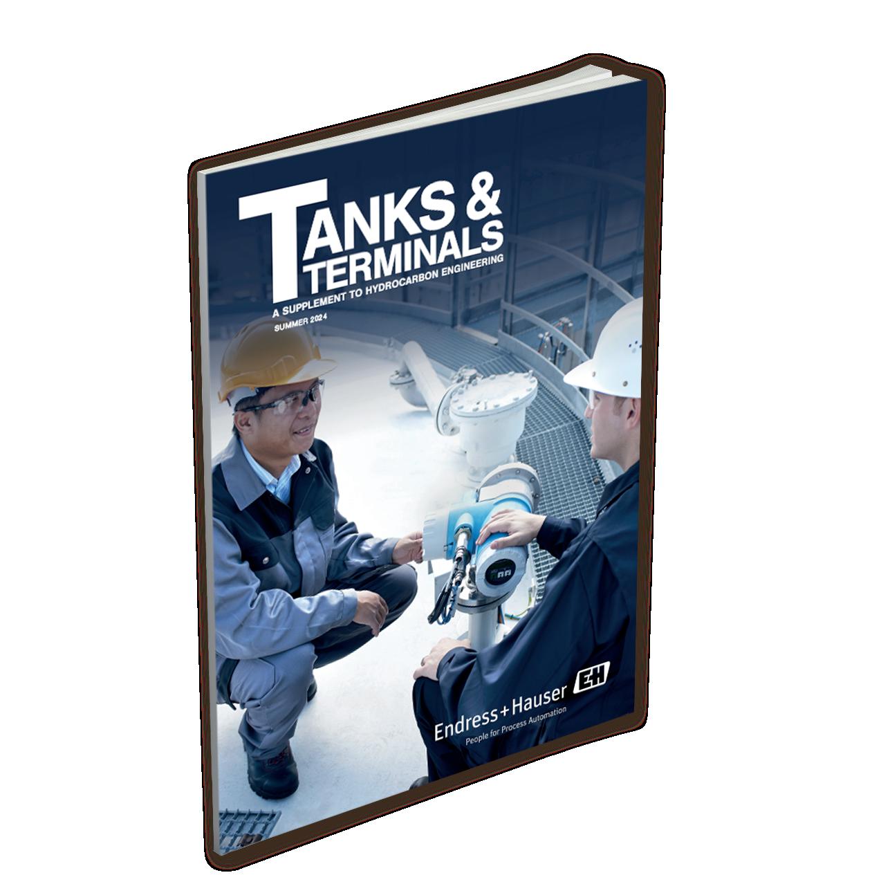
Daniel Hoy, Endress+Hauser, details how dependable factory calibration can save time during commissioning and provide improved accuracy assurance.
Gordon Cope, Contributing Editor, reveals the developments and opportunities in the energy storage industry across North America.

11 Harnessing the waste heat
W. T. Cutts, American Tank & Vessel Inc., USA, outlines the next steps for existing liquid storage terminals in their transition to clean energy by utilising waste heat.
15 Preparing for the energy transition
Mike Sies, JLA Loading Technology, the Netherlands, explains why next generation loading equipment is required to create a safe transportation network for liquid ammonia and liquid carbon dioxide.


25 The right radar
Håkan Enarsson, Emerson, USA, explains the advantages non-contacting radar level gauges provide when measuring the level of used cooking oils for inventory management and overfill prevention purposes.
29 Corrosion conversations
Tim Bovard, Owens Corning, USA, examines the main corrosion-related difficulties faced by the tank storage industry as discussed during the recent AMPP Annual Conference.
33 Beyond the leak
Debra Hall, Elementale Enterprises Inc., explores an alternative method used for protecting metal components from corrosion.
37 Seeking safer solutions
Brian McHale, Carboline, USA, outlines how an industrial coating crew trialled the use of a remote abrasive blaster during a tank refurbishment.
41 Slogging through the sludge
Danny Constantinis, EM&I Group, discusses the use of technology to see through the sludge in tanks.
45 Making a plan
Dave Godfrey, Rotork, UK, outlines how an effective maintenance plan can reduce downtime, increase profitability and improve safety at tank farms.
49 Keep cool in challenging conditions
Sébastien Vermeulen, Trillium Flow Technologies, France, explains how valves have been designed to address the unique challenges of the LNG market.
53 Shore power systems for tankers
Thomas Hartmann, DNV, Norway, discusses the updated Shore Power class notation, which addresses the safety requirements for tankers lying at berth.
New Endress+Hauser calibration rigs in service
High-precision calibration equipment enables processors to use reliable measurement devices from the factory, eliminating the need for on-site calibration during commissioning and providing a higher level of confidence throughout the operational lifecycle. Learn how analytical reporting software and smart device diagnostics help save time and optimise processes.
Summer 2024 Volume 10 Number 02 ISSN 1468-9340 CONTENTS Tanks & Terminals Like Join Tanks and Terminals @TanksTerminals Follow JOIN THE CONVERSATION Copyright© Palladian Publications Ltd 2024. All rights reserved. No part of this publication may be reproduced, stored in a retrieval system, or transmitted in any form or by any means, electronic, mechanical, photocopying, recording or otherwise, without the prior permission of the copyright owner. All views expressed in this journal are those of the respective contributors and are not necessarily the opinions of the publisher, neither do the publishers endorse any of the claims made in the articles or the advertisements. Printed in the UK. THE FRONT COVER 03 Comment 05 World news 06
Navigating North America’s energy hubs
CBP019982
BY DESIGN ®
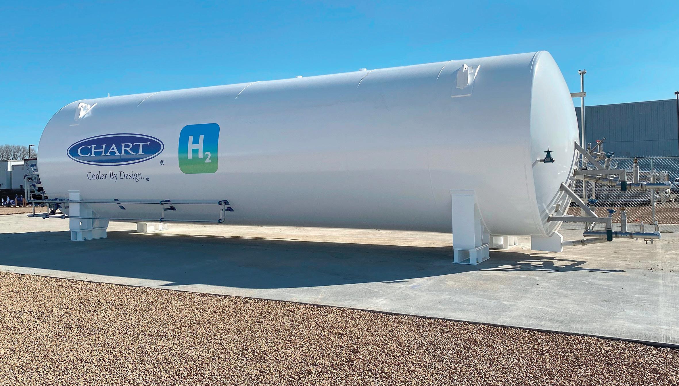
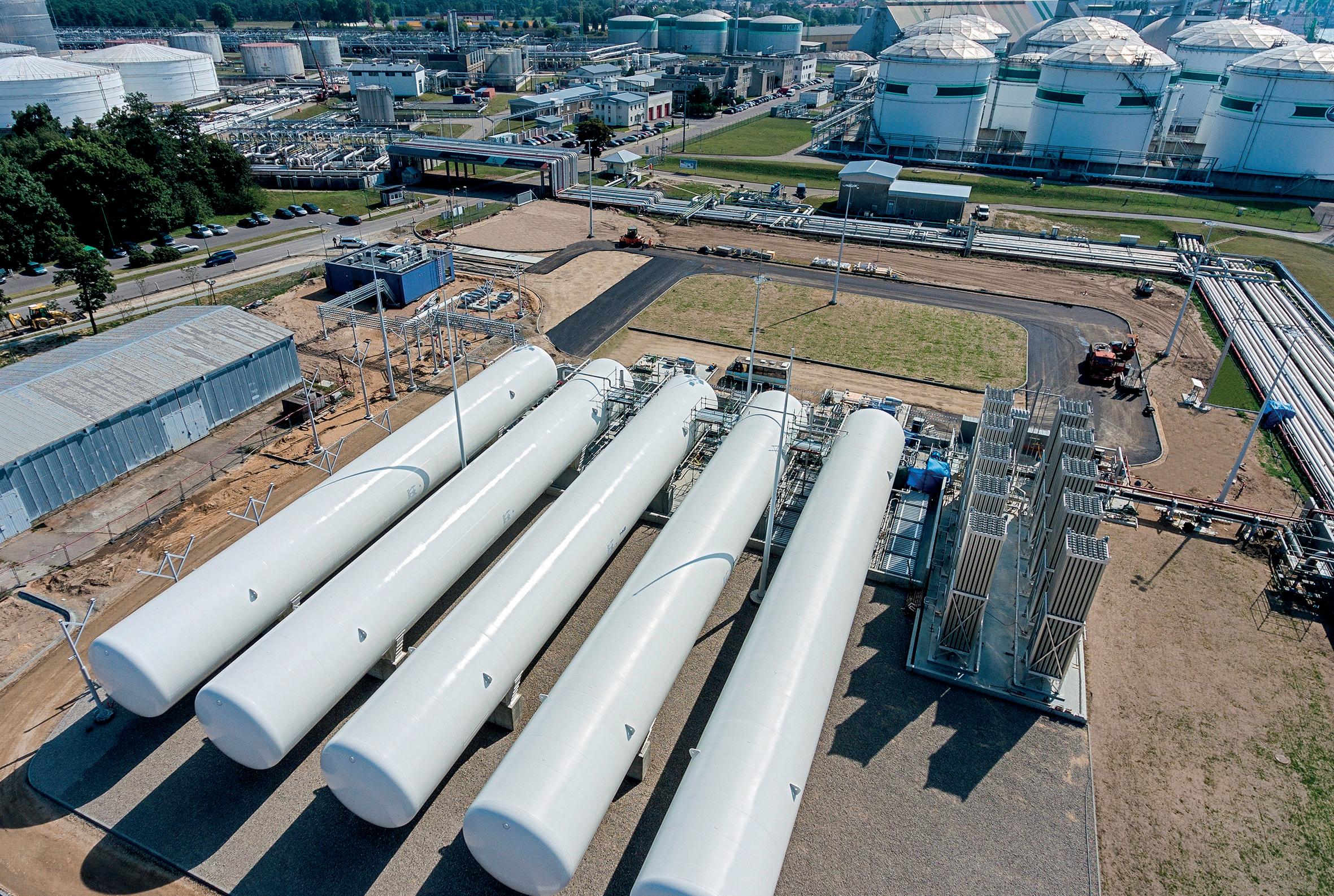
Chart cryogenic storage products are integral to the virtual pipeline facilitating increased energy independence and security through LNG and liquid hydrogen. By utilizing cryogenics to store gas in liquid form the tanks are much smaller than their gaseous equivalents. Cryogenic tanks are shop built and total storage capacity is modularized, reducing project cost, complexity, risk and timescale.
chart.europe@chartindustries.com
CONTACT INFO COM MENT
MANAGING EDITOR James Little james.little@palladianpublications.com
SENIOR EDITOR Callum O’Reilly callum.oreilly@palladianpublications.com
EDITORIAL ASSISTANT Oliver Kleinschmidt oliver.kleinschmidt@palladianpublications.com
SALES DIRECTOR Rod Hardy rod.hardy@palladianpublications.com
SALES MANAGER Chris Atkin chris.atkin@palladianpublications.com
SALES EXECUTIVE Sophie Barrett sophie.barrett@palladianpublications.com
PRODUCTION MANAGER Kyla Waller kyla.waller@palladianpublications.com
EVENTS MANAGER Louise Cameron louise.cameron@palladianpublications.com
DIGITAL EVENTS COORDINATOR Merili Jurivete merili.jurivete@palladianpublications.com
DIGITAL CONTENT ASSISTANT Kristian Ilasko kristian.ilasko@palladianpublications.com
DIGITAL ADMINISTRATOR Nicole Harman-Smith nicole.harman-smith@palladianpublications.com
ADMIN MANAGER Laura White laura.white@palladianpublications.com
CONTRIBUTING EDITOR Gordon Cope
SUBSCRIPTION RATES
Annual subscription £110 UK including postage /£125 overseas (postage airmail).
Two year discounted rate £176 UK including postage/£200 overseas (postage airmail).
SUBSCRIPTION CLAIMS
Claims for non receipt of issues must be made within 3 months of publication of the issue or they will not be honoured without charge.
APPLICABLE ONLY TO USA & CANADA
Hydrocarbon Engineering (ISSN No: 1468-9340, USPS No: 020-998) is published monthly by Palladian Publications Ltd GBR and distributed in the USA by Asendia USA, 17B S Middlesex Ave, Monroe NJ 08831. Periodicals postage paid New Brunswick, NJ and additional mailing offices. POSTMASTER: send address changes to HYDROCARBON ENGINEERING, 701C Ashland Ave, Folcroft PA 19032
15 South Street, Farnham, Surrey
GU9 7QU, UK
Tel: +44 (0) 1252 718 999
 CALLUM O’REILLY SENIOR EDITOR
At the start of the energy crisis in 2021, not many would have predicted that Europe would emerge from consecutive winter seasons with its energy system unscathed. At the end of April, European gas storage stood at 62% full, which is above the five-year average of 47%, as well as the 60% in the corresponding period of last year.1 This has left the continent in a comfortable position to refill its gas storage over the summer months.
Europe’s decision to increase LNG imports and its successful introduction of gas-saving measures have been key to its resilience over the past two years, as has the fact that the region has benefitted from a couple of mild winters. The continent’s ability to ride out a harsh winter has yet to be tested. Speaking recently at the Europe Flame Gas and LNG Conference in Amsterdam, Cara MacDonald, Head of LNG and Clean Fuels Supply at RWE Supply and Trading, said: “Had we had a cold winter, or if we have a cold winter, this year [or] next year, the amount of flexibility on the demand side will diminish more significantly.”2 The clear message is that the industry must not be complacent, as things can change very quickly.
However, for now, analysts are warning that the EU may need to scale back its imports of LNG in the coming months to ensure that it does not fill its storage capacity too early. Natasha Fielding, Head of European gas pricing at Argus Media, believes Europe has a “problem of plenty” this summer, with the possibility that the bloc could achieve its target of 90% capacity by the start of November in early August if the pace of injection is similar to last year. Fielding said: “Europe may need to take less LNG this summer to balance out weaker demand and slow the pace of the stock build, thereby avoiding sites filling early.”3
In the Autumn 2023 issue of Tanks & Terminals, I commented on how Europe was turning to Ukraine to store excess gas reserves in the country’s underground gas storage (UGS) sites. Oleksiy Chernyshov, the CEO of Naftogaz – Ukraine’s national energy company – has now called on EU countries to help protect its storage infrastructure following a number of Russian attacks. Aboveground storage sites in the west of the country have suffered damage following Russian shelling, while its UGS facilities have also been targeted. Following an attack on an underground facility in March, Chernyshov said that storage and capacity booking continued to be fulfilled as planned: “The situation will not critically impact the UGS operations since the gas is stored deep underground. The damaged surface infrastructure will need repairs, however we have sufficient backup capacities in place to mitigate any immediate impacts.” Despite the attacks, Naftogaz hopes to increase the amount of European natural gas stored in its facilities from 2.5 billion m3 last year to 4 billion m3 this winter.4 Ukraine also continues to operate as a transit route for Russian pipeline gas into Europe, under a deal signed between Naftogaz and Gazprom in 2019, which will finish at the end of this year. As Chernyshov has argued in an interview with the Financial Times: “It is of interest of the EU to protect storage, transportation and production [facilities]”, given that Ukraine’s gas infrastructure is “well integrated” into Europe’s energy system.4
1. PATTERSON, W., ‘European gas rallies despite bearish outlook’, ING, (7 May 2024).
2. RASHAD, M., ‘Europe’s ability to survive a cold winter hasn’t been tested, energy execs say’, Reuters, (23 April 2024).
3. TANI, S., ‘EU exits winter with gas storage at record levels’, Financial Times, (2 April 2024).
4. TANI, S., ‘Ukraine energy chief calls on EU to help protect gas storage from Russia’, Financial Times, (30 April 2024).
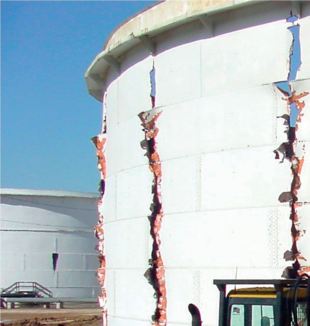
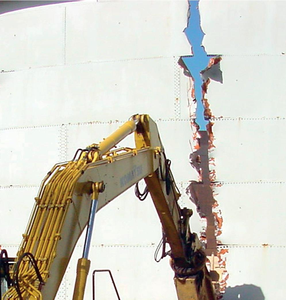








SAFE AND COST-EFFECTIVE DEMOLITION SERVICES FOR TANK AND TERMINAL OWNERS AND CONTRACTORS (713) 991-7843 www.midwest-steel.com demolition@midwest-steel.com
WORLD NEWS
EU Commission releases statement on European gas storage levels
EU Commissioner for Energy Kadri Simson has reported that on 31 March 2024, when the winter heating season ended, European gas storages were over 58% full.
Arabian Chemical Terminals LLC in Abu Dhabi begins operations
Arabian Chemical Terminals LLC in Abu Dhabi (ACTAD) has announced the start of operations at its newly built chemical tank storage terminal in Khalifa Port, Abu Dhabi, UAE. The terminal is the first commercial chemical tank farm of its kind in the Emirate.
CB&I awarded LNG tank contract by TotalEnergies
CB&I, a wholly-owned, unrestricted subsidiary of McDermott, has been awarded a contract by Marsa Liquefied Natural Gas LLC, a joint venture between TotalEnergies and OQ, for the engineering, procurement, and construction (EPC) of a full containment concrete LNG storage tank, located in Oman’s Port of Sohar.
VTTI and IKAV enter agreement to purchase Adriatic LNG
VTTI and IKAV have entered a consortium to acquire the majority ownership of Terminale GNL Adriatico Srl, also known as Adriatic LNG, which operates the regasification terminal located 15 km off the coastline of the Veneto region in Italy.
Adriatic LNG terminal has a technical regasification capacity of 9.6 billion m³/y of natural gas, supplying approximately 14% of the country’s national consumption of natural gas.
To keep up-to-date with the latest news and developments in the storage sector, visit www.tanksterminals.com and follow us on our social media platforms

26 27 June 2024
Downstream USA Galveston, Texas, USA events.reutersevents.com/petchem/downstream-usa
20 22 August 2024
Turbomachinery & Pump Symposia Houston, Texas, USA tps.tamu.edu
5 September 2024
World Energy Transition Conference Virtual www.accelevents.com/e/worldenergytransition2024
17 20 September 2024
Gastech Houston, Texas, USA www.gastechevent.com
07 10 October 2024
API Storage Tank Conference & Expo Fort Lauderdale, Florida, USA events.api.org/2024-api-storage-tank-conference-expo
10 12 December 2024
17th Annual National Aboveground Storage Tank Conference & Trade Show The Woodlands, Texas, USA www.nistm.org
11 12 March 2025
StocExpo Rotterdam, the Netherlands www.stocexpo.com


READ MORE... Tanks
Terminals Like Join Tanks and Terminals @TanksTerminals Follow DIARY
&
DATES
A selection of the latest news hitting the headlines on www.tanksterminals.com
Summer 2024 5

Gordon Cope, Contributing Editor, reveals the developments and opportunities in the energy storage industry across North America.
Summer 2024 6

Between them, Canada and the US account for approximately 18% of global crude oil production and 32% of natural gas output. Both commodities are increasingly being exported around the world, creating a significant demand for new tank and terminal facilities in North America.
Canada
The oil sands in northern Alberta are the powerhouse for growth in Canadian production. It presently stands at 3.2 million bpd of bitumen and synthetic crude oil, but is set to grow significantly over the near future as producers add capacity. Canadian Natural Resources announced that it intends to grow its 1.4 million bpd output by approximately 5% over the next two years, and Cenovus has plans to add another 80 000 bpd by the end of the decade.
The reason for the expected spurt is the imminent commissioning of the Trans Mountain Expansion (TMX). At a cost of over CAN$30 billion, the 300 000 bpd crude line from Edmonton to tidewater ports near Vancouver has been expanded to 890 000 bpd capacity.
In addition to the pipeline, Trans Mountain has enlarged the Burnaby tank terminal and nearby Westridge Marine Terminal in the port of Burnaby, British Columbia (B.C.). Previously, the Burnaby terminal had 13 tanks with a capacity of 1.6 million bbl; the expansion added 13 more tanks and
Summer 2024 7
doubled capacity. The Westridge marine terminal was able to handle one aframax tanker (approximately 600 000 bbl); a new dock complex allows the facility to load up to three aframax tankers and handle around three dozen vessels per month.
Presently, Canada exports approximately 4 million bpd to the US, which is expected to rise to 4.2 – 4.4 million bpd by 2026. Several major crude terminals in Alberta store product destined for export to the US. The largest is in Hardisty, Alberta, which sits astride several major crude pipelines. Crude producers, pipeline companies and infrastructure firms operate at the site, including Enbridge (16 million bbl), Husky (4.9 million bbl) and Gibson Energy (13.5 million bbl). Gibson has budgeted CAN$150 million – CAN$200 million per year in new tanks for the next several years.
One of the fastest growing natural gas plays in Canada has been the unconventional Montney shale in northeast B.C. and northwest Alberta. Production stands at 10 billion ft³/d, and is expected to grow to 18 billion ft³/d by the end of the decade.
West Coast LNG projects are expected to absorb a healthy portion of that growth. LNG Canada, led by Shell, is building a plant in Kitimat, B.C. The first phase of 14 million tpy is scheduled for completion in 2025. The facility will be fed by the recently completed 2.2 billion ft³/d Coastal GasLink pipeline. The pipeline, which can be expanded to 5 billion ft³/d, is expected to serve other LNG plants. The 2.1 million tpy Woodfibre LNG plant near Squamish, B.C., has a completion date set for 2027. In March 2023, the B.C. government approved the construction of the Cedar LNG Project, also near Kitimat. The CAN$2.4 billion floating LNG facility, which is majority-owned by the Haisla First Nation, is expected to produce up to 4 million tpy.
For the last several years, AltaGas has been operating the Ridley Island Propane Exporting Terminal (RIPET), located in the deep-water port of Prince Rupert, B.C. Approximately 50 000 bpd is loaded onto very large gas carriers (VLGCs) for delivery to Asia. Demand for propane is strong in Asia, and AltaGas alongside partner Vopak have announced they were in the advanced stage of planning to build the Ridley Energy Export Facility (REEF), a versatile facility capable of handling a variety of commodities, including propane and butane. The expansion would add 50 000 to 60 000 bpd of capacity, at a cost of approximately CAN$500 million. In addition, the new facility would have the potential to export green ammonia to Asian markets as a leading candidate for low-carbon marine fuels.
US
Thanks largely to the development of unconventional resources, the US is the world’s largest producer of fossil energy, averaging around 13 million bpd of crude and 96 billion ft³/d of natural gas. The Permian basin, located in Texas and New Mexico, has become the primary engine of growth, as it edges toward 6 million bpd and 18 billion ft³/d of associated gas.
The proximity of this production to the Gulf of Mexico offers tremendous export opportunities. Permian output is generally low-sulfur light crude, unsuited to refineries in Texas and Louisiana, which rely on heavier feedstock. While some refineries are retooling to handle sweeter crudes, plants in China and Southeast Asia are willing to pay a premium and are avidly seeking out shipments, as are European refiners who have had Russian shipments curtailed by the war in Ukraine. According to the Energy Information Administration (EIA), USGC (PADD 3)
exports averaged 2.48 million bpd in 2021; by late 2023, that number had grown to 4.4 million bpd.¹
Subsequently, this creates a problem. Most long-distance crude shipments travel via very large crude carriers (VLCCs), with capacities of 2 million bbl. Marine terminals in the Gulf of Mexico were designed with smaller, regional deliveries in mind, such as across the US Eastern Seaboard and Mexico, so port drafts were dredged to handle smaller aframax vessels carrying 750 000 bbl. VLCCs are thus filled using ‘reverse lightering’, in which smaller tankers load them offshore.
As a result, exporters have been angling for new port infrastructure to handle VLCCs. In late 2022, the Biden administration approved the development of the Enterprise Products Partners’ offshore Sea Port Oil Terminal (SPOT) in Freeport, Texas, approximately 30 km south of Houston. When the terminal comes online in 2027, it will be able to fill VLCCs at a rate of 85 000 bph.
Over the last several years, Enbridge has been beefing up its export facilities in Corpus Christi, Texas. The Enbridge Ingleside Energy Centre (EIEC) is the largest crude oil storage and export terminal by volume in the US, with an approximate storage capacity of 15.3 million bbl and docks capable of berthing VLCCs. In early 2024, it announced that it would be spending approximately US$300 million to add 2.5 million bbl of new storage and to purchase two marine docks adjacent to EIEC.
Additionally there is Cushing, Oklahoma, which is at the crossroads of several major pipelines and serves as the major crude terminal in North America. Eight companies, including Enbridge, Plains All American, Magellan and Energy Transfer, own the majority of storage assets. The terminal has a nameplate capacity of 98 million bbl, but a working capacity of around 76 million bbl (the farms have to maintain approximately 20 million bbl to ensure functionality). Over the course of a year, stockpiles can fluctuate by tens of millions of bbl due to refinery and pipeline maintenance and demand. In September 2023, stockpiles fell to under 23 million bbl due to strong exports to Asia and Europe. Stockpiles rose again during the planned refinery maintenance period, but rising exports will continue to place pressure on storage. Demand will also be further strengthened by the construction of a new refinery in the city. In May 2023, Prairie Energy partners announced that it would build a greenfield 250 000 bpd plant designed to produce low-carbon fuels using blue hydrogen. A start-up date has yet to be announced for the US$5.6 billion facility.
Meanwhile, LNG has grown to be a massive export commodity in the Gulf of Mexico, and expansion is expected to continue for most of the decade. Trade averaged just under 12 billion ft³/d in 2023; over the next three years, capacity is expected to increase by a combined 5.7 billion ft³/d as new plants come on-stream. Sempra is developing the Port Arthur LNG project; Phase 1 foresees two trains with a capacity of 10 million tpy (1.3 billion ft³/d). Qatar Energy and ExxonMobil are currently constructing the Golden Pass LNG project in Texas. The US$10 billion complex could eventually have up to 18 million tpy capacity. Energy Transfer plans to build the Lake Charles LNG project at its current LNG import site in Louisiana. Venture Global announced plans to build the Plaquemines LNG terminal in Louisiana, 30 km south of New Orleans; Phase 1 will include 18 modular mini-trains with a total of 11.3 million short tpy capacity and Phase 2 will almost
8 Summer 2024
API’s Process Safety Site Assessment Program (PSSAP®) enlists expert third-party assessors to evaluate existing process safety programs at refining, chemical and petrochemical facilities.
Assessments are based on industry-developed protocols, including the Product Storage & Transfer protocol that aims to prevent loss of containment and mitigation measures while improving operations.
PROMOTES SAFETY AND CONTINUOUS IMPROVEMENT
® © 2024 – American Petroleum Institute, all rights reserved. API, PSSAP and the API and PSSAP logos are trademarks or registered trademarks of API in the United States and/or other countries. API Marketing & Communications: 2024-150 | PDF www.API.org/PSSAP To learn more visit:
PSSAP
double capacity to 20 million short tpy. The total cost of both phases is estimated at US$20 billion.
Greenfield LNG projects typically require extensive tank and terminal construction. The cost of a 200 000 m³ LNG storage tank is approximately US$250 million. While most existing terminals can handle standard 150 000 m³ LNG tankers, the next generation of 250 000 m³ tankers (similar in size to VLCCs) will require extensive draft and pier improvements.
Green fuels
Both Ottawa and Washington have established net-zero goals for wide swaths of their economies by 2050. They are also incentivising companies to invest in environmentally friendly projects that create renewable fuels in North America. In addition to establishing subsidies and tax credits for green hydrogen production under the Inflation Reduction Act, the Biden administration announced it had selected seven clean-energy hubs around the country for a US$7 billion programme to kick-start development and production of hydrogen fuel. The Gulf Coast Hydrogen Hub will be established in the Houston area to take advantage of energy industry know-how and existing hydrogen markets. These opportunities include the following:
n In late 2023, OCI Global reached an agreement with New Fortress Energy to buy all clean hydrogen output from the latter’s ZeroPark 1 project in Texas. The 200 MW plant is expected to produce approximately 17 000 tpy of hydrogen, which OCI will then convert to 80 000 tpy of green ammonia at its Beaumont complex. Plans are underway to double capacity to 160 000 tpy by 2026, as OCI is eyeing exports to Europe, where the EU has established a target of renewable fuels of non-biological origin (RFNBOs) in industrial usage of 42.5% by 2030.
n German-based RWE formed an alliance with LOTTE Chemical, of South Korea, and Japan’s Mitsubishi to build a clean ammonia production and export facility in the port of Corpus Christi, Texas, US. The plan is to build a series of units with a final capacity approaching 10 million tpy by 2030. Output will be in the form of both blue and green ammonia, and will be exported to Asia and Europe for use as both fuel and a source of renewable hydrogen.
n Cresta Fund Management, a private equity firm, purchased the idled Come-by-Chance refinery in Newfoundland, Canada. The 135 000 bpd refinery, to be called Braya Renewable Fuels, will focus initially on producing 14 000 bpd of sustainable aviation fuel (SAF). Further plans include doubling capacity to 27 000 bpd. Braya is currently in discussions with ABO Wind to supply 35 000 tpy of green hydrogen.
n Yara, a fertilizer company based in Norway, is teaming up with Enbridge to build a blue ammonia plant in Corpus Christi. The US$2.9 billion facility will produce up to 1.4 million tpy using carbon capture. The output will be used for low-carbon fertilizers, shipping fuel, and utility power. If confirmed through front-end engineering and design (FEED), production would start-up in 2027/2028.
Both hydrogen and ammonia require bespoke facilities to store and transport; greenfield projects will require massive investments for tanks and terminals.
Challenges
In January 2024, the Biden administration ordered a pause on pending and future LNG permits that allow exports to non-free trade agreement jurisdictions until the US Department of Energy (DOE) finishes a review of climate impacts. The pause does not affect existing exports and projects currently underway, but could compromise several billion-dollars-worth of expansions that have been planned but not permitted.
Regardless, the move was seen by the natural gas sector as an election-year gesture toward environmentalists, and they lobbied the Republican-held Congress to pass a bill designed to strip the DOE of its export review powers. While advocates of the pause cite savings to American consumers, there is little evidence that LNG exports are indeed causing higher prices. While the pace of gas drilling in the Utica shales of Pennsylvania is sensitive to the price of gas, drilling in the Permian is dictated by the price of oil. The Henry Hub gas spot price has been languishing around US$3/1000ft³ during the 2023 – 2024 winter season despite rising LNG exports; spot gas prices even fell into negative territory at the Waha hub in west Texas several times in 2023 when high production, takeaway bottlenecks, and mild weather occurred simultaneously.
Some green hydrogen projects are proving to be too costly. In early 2023, Nutrien announced plans to build the world’s largest clean ammonia facility at its existing complex in Geismar, Louisiana, near tidewater ports in New Orleans. The 1.2 million tpy plant would permanently remove up to 90% of CO2 emissions using carbon capture and sequestration (CCS) technology. But later that year, the Canadian company placed the project on hold, citing increased construction costs and uncertainty over the premium market for clean ammonia.
In March 2024, the head of ExxonMobil said that its proposed hydrogen facility in Baytown, Texas, might not move ahead unless the tax credit incentives in the Inflation Reduction Act were adjusted to include blue hydrogen. The facility, which is slated to enter service by 2028, would produce 1 billion ft³/d of low-carbon hydrogen by capturing and sequestering 98% of CO2 output. “We’re investing billions of dollars to reduce the carbon intensity of our natural gas,” said CEO Darren Woods. “Why would the regulation not give companies doing that any credit? That will basically instantly stop investments to reduce carbon intensity by the industry as a whole.”²
Conclusion
In conclusion, the future of tanks and terminals in North America is bright. Energy in all forms is in demand throughout the world, and North America is ideally suited by geography and geology to service both Europe and Asia. Terminals for conventional crude oil and LNG are being built and expanded, while green fuels offer substantial opportunities. Companies positioned to offer both existing and new assets pertaining to infrastructure can expect substantial growth.
References
1. https://www.eia.gov/dnav/pet/PET_MOVE_EXPCP_D_R30_Z00_ MBBLPD_M.html.
2. https://www.dailyoilbulletin.com/article/2024/3/20/exxon-ceo-sayshydrogen-project-at-risk-without-ir/
10 Summer 2024
W. T. Cutts, American Tank & Vessel Inc., USA, outlines the next steps for existing liquid storage terminals in their transition to clean energy by utilising waste heat.
For the future of the liquid terminal industry, nothing is more important than engagement in a solution for the energy trilemma (affordability, security, and sustainability). Engagement here must be defined as building a profitable terminal business around the energy trilemma. Some investors are starting to distance themselves from the hydrocarbon industry, and publicly traded companies are faced with the challenge of satisfying a broad range of investors on the path forward. Therefore, the terminal industry needs a plan to support positive economic results, capitalising on an energy transition solution. The good news is, there are opportunities to reformulate existing terminals to leverage the clean energy future. The solutions involve emission reductions, storage

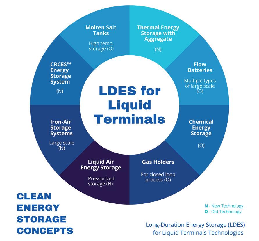
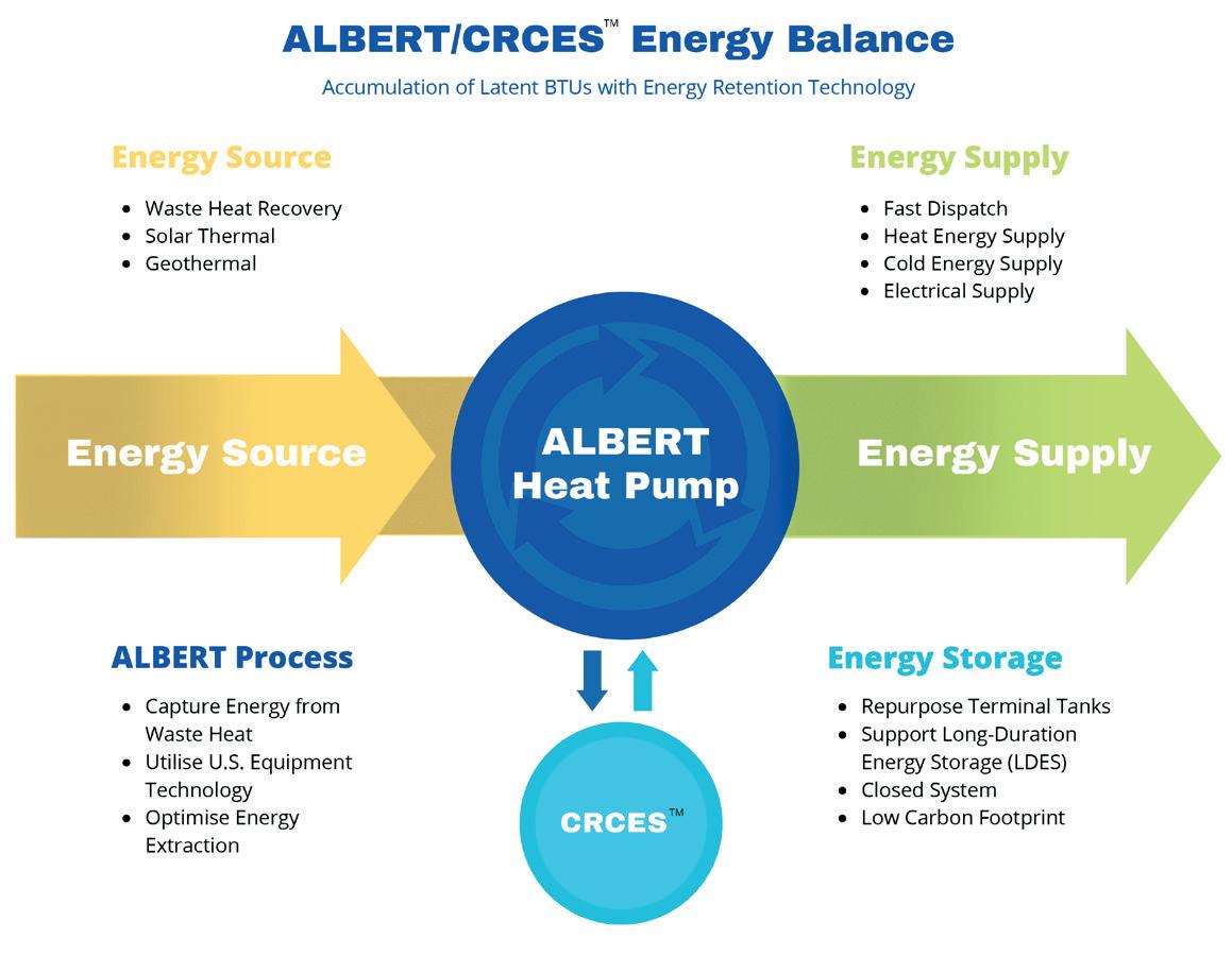
of products generated through renewable efforts, optimisation, and new technologies, which take advantage of existing terminal infrastructure, systems, and locations. A number of leading technologies that support terminals are listed in Figure 1. One of the new exploitable technologies for liquid terminals is the CRCESTM (carbon reduction clean energy storage) system. This process works well in bulk storage terminals. CRCES works with an industrial heat pump to accumulate energy from waste heat, then stores the energy in tanks. Another technology for waste heat storage is the use of thermal energy with liquid or aggregate in tanks. Both systems can be profitable in the short-term for terminals with the right criteria.
The most viable solutions must harness current terminal assets, store energy, and at the same time secure
Summer 2024 11
a renewable means of power generation. The combination of these efforts paints a picture of transition accepted by the most aggressive investors. As a reference point for terminal competition, one need look no further than lithium-ion
batteries for electrical energy storage (EES). When it comes to power generation, solar and wind are the systems to beat. The liquid terminal industry can outperform photovoltaic (PV) solar with batteries by supporting long-duration energy storage (LDES), lower EES cost, and a lower carbon footprint among other things.
When embracing new technology, from an investor perspective, there are plenty of selling points, but the big challenge is favourable economics. The solutions lie in old concepts and technologies formulated to fit the liquid terminal industry. Taking advantage of the location of many terminals, specifically their proximity to industrial facilities and power grids, is a key element for success.
Thermal energy storage systems and CRCES technology are simply types of waste heat recovery and clean bulk energy storage that compete with solar, wind, and batteries. Compared to clean power generation paired with batteries, these systems offer unlimited life cycles, no cost of future battery replacement, a smaller area requirement for energy storage, and efficient LDES. These systems also have faster project timelines, provide more local jobs compared to deploying batteries, and offer a lifespan of over 20 years.
Moving forward, the realisation of these benefits requires a commitment to working with the energy industries in the vicinity of the existing terminal. One valuable source of energy is low-quality waste heat. Most industries already utilise waste heat recovery in a variety of manners, but still have low-quality waste heat within their operations. Typical operations consume water, power, chemicals, and land area to expel this low-quality waste heat. Technologies are available to utilise low-quality waste heat, as well as convert existing storage tanks and systems to serve as energy storage containers. A front-end engineering design (FEED) study identifies the resources which can be utilised for energy acquisition, storage, and distribution. Terminal companies who embrace the concept are underwriting their future by:
n Promoting a path to clean energy storage with investors.
n Adding long-term sources of revenue.
n Reducing local industrial consumption of water.
n Expanding relationships with local industries.
n Stabilising the power grid with clean energy.
Utilising existing terminal assets for the storage of clean energy can be accomplished through several applications which support legacy technologies. However, a review of these applications shows that many do not take advantage of a traditional hydrocarbon terminal’s assets. For applications to have a good fit, the projects need to utilise current physical assets, support deployment, leverage existing staff and systems, acquire low-cost energy, incorporate good economics, show flexibility for future transitions, and minimise the land required for new equipment.
Most clean energy storage is either burdened with incomplete technology or limited by rare materials. Thermal energy storage and CRCES technology are available for commercialisation and have the benefit of storing energy from low-quality waste heat sources.
Figure 1. Chart of long duration energy storage (LDES) for liquid terminal technologies.
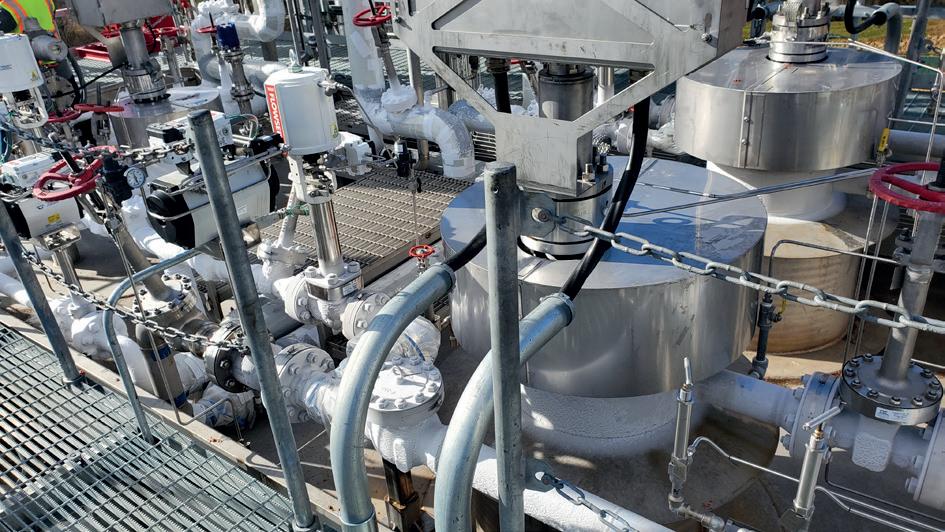
Figure 2. Clean energy process piping.
12 Summer 2024
Figure 3. Flow chart of the CRCESTM process.




ADVERTISEMENT FEATURE
These systems can utilise nearly the full storage potential of existing tanks, with minimal modifications. Not only are the assets of a liquid terminal utilised, but the terminal’s management systems are appropriate to operate the updated facilities described. Many liquid terminals operate propane facilities or blending, which are of similar complexity to operating the facility supported by CRCES. In addition, most terminals are in areas where it is easy for the terminal to tie itself into the electrical grid, support a substation, generate behind the metre, or work through an electrical broker to sell power.
Utilisation of a terminal’s fixed assets will require tanks, a processing unit, thermal piping into the terminal facility, and power grid connectivity. Overall, most facilities have plenty of space for the inbound thermal piping which is used to bring the energy into the terminal. The overall processing facility area is minimal. For example, a 1 GW storage facility would only require a processing area of approximately 100 ft x 200 ft. Tying into the grid is a function of the existing plant, the grid style, and the dispatch rate. This may require additional work with the grid management group, however, the system is very small overall (except for the storage tanks).
Most of the required modifications to existing systems for the implementation of clean energy storage in a terminal occurs in the tanks themselves. There are a variety of applications for
storing energy in tanks, from molten salt to chilled water, but there are different requirements for storing heated liquid, heated aggregate, and/or mixed refrigerant liquids. However, the common requirement is a good insulation system. In some situations, the existing tanks can be the primary containment structure for the substance that will store the energy. However, in many applications the existing tank will become the outer tank with a second tank being constructed inside the existing tank and the outer tank acting as an insulation jacket and/or a secondary containment vessel.
Tank alterations will take into consideration the stress and thermal performance levels of the existing foundations and steel structures. Older tanks (or tanks that are somewhat corroded) may fully qualify to act as the insulation jacket. All tank modifications, whether dealing with foundations, piping systems, venting and/or overall performance, will comply with required standards, codes, stakeholder requirements, and appropriate certifications. Investigations will need to be performed to ensure minimum risk and liability to investors, terminal employees, the environment, and the public. Some designs may require that the existing tank roof be removed and that the inner tank becomes a primary roof extending over to the old tank’s outer shell when reviewing these options with a terminal owner. A variety of options are presented to ensure the solutions are economically viable and perform accurately for the new storage substance, and that thermal requirements are realised.
The power customer is very different from the traditional terminal customer. Power generation facilities can have long contracts with a theoretical customer or customer base that is very stable. The same should be true for clean energy storage in terminals. Ultimately, a power purchase agreement (PPA) or contract with the appropriate grid management firms leads to a long revenue stream that can see inflation and other pricing enhancements included in the terms.
In addition to stable power generation revenue, clean energy incentives should also be realised, and the ability to help stabilise the grid against intermittent power supplies volatility. The systems described here will give terminals LDES capabilities so that arbitrage and opportunities with higher power rates should be realised. In addition, the number one competitor for terminals in clean energy storage is lithium-ion batteries. Competing directly against lithium-ion batteries is an additional financial advantage that terminals have because of the long life of the LDES systems within hydrocarbon terminals vs the short life of lithium-ion batteries and battery replacement issues.
Conclusion
Hydrocarbon terminals are not alone in searching for solutions to the global energy transition. Terminals, however, have an advantage over many industries through the utilisation of current assets, combined with geographic location and the history of being an energy storage provider. By working with industries in relative proximity to the terminal for accumulation of waste heat, modifying existing storage tanks, and utilising their proximity to large electrical grids is a winning trifecta for hydrocarbon terminals. This solution attracts new investors, builds new long-term relationships, and repurposes existing assets with a better return on investment. Such an undertaking is hard work but offers great rewards.
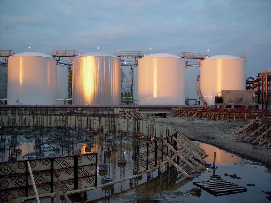
Figure 4. AT&V’s construction of pressurised storage for hydrocarbon terminals.
14 Summer 2024
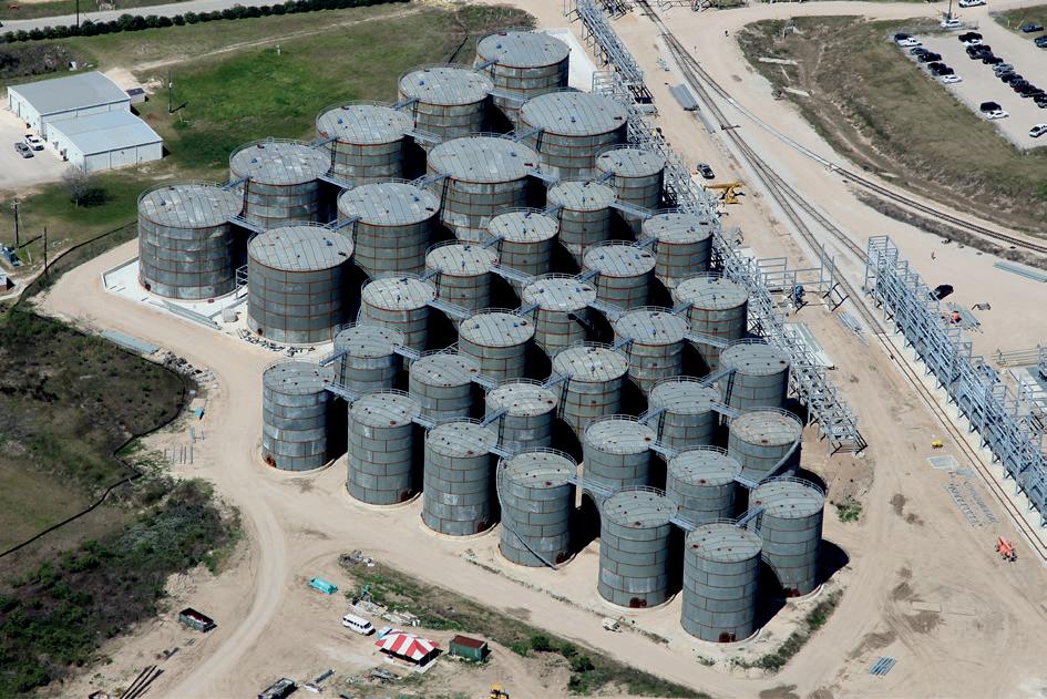
Figure 5. Typical atmospheric storage facility featuring 36 tanks built by AT&V.
Mike Sies, JLA Loading Technology, the Netherlands, explains why next generation loading equipment is required to create a safe transportation network for liquid ammonia and liquid carbon dioxide.
As the world seeks to transition towards cleaner energy alternatives, hydrogen has emerged as a promising solution. However, one of the major challenges associated with hydrogen is its transportation. To address this issue, ammonia has gained traction as a carrier for hydrogen molecules. Ammonia offers the advantage
Summer 2024 15
of being easily transportable and has the potential to play a crucial role in the global energy supply chain. The challenge with ammonia is that it is dangerous for humans and hence the potential for leakages and spills should be eliminated.
Loading arms
Loading arms serve as essential infrastructure for loading and unloading liquids or gases into and from vessels at port facilities. When it comes to transferring ammonia, it is imperative to consider the specific requirements for efficient, reliable, and safe operations. It is essential to consider the following when designing and building loading facilities for ammonia:
n Enhancing efficient loading processes.
n Safe and ergonomic operations.
n Minimum and easy maintenance.
Efficient loading process
To enhance the efficiency of the loading process it is important to keep the docking time of the ship as short as possible and load/unload the ship quickly. In order to achieve this, it would be desirable to have a loading arm
with maximum product flow and minimum pressure drop. In addition, the connection to the ship, and disconnection from the ship, should be as quick and easy as possible.
Minimum swivel joints
The pressure drop in loading arms can be kept as low as possible by choosing a design with minimal swivel joints and elbows. As such, the loading arm should be configured as asymmetric with a single base riser, a single inboard arm and a single outboard arm with a total of only six swivel joints to accommodate the six degrees of freedom of ships. This design not only reduces pressure drop but also minimises potential leakage points, which is crucial for handling hazardous substances such as liquid ammonia.
The additional advantage of an asymmetric design is that the capacity of the product pump in the plant process line or on the ship can be smaller – as is the case for loading arms with higher pressure drops – and the energy of those pumps can be less. It would be an interesting exercise to calculate the energy savings using a loading arm with a lower pressure drop compared to others.
The pressure drop of loading arms heavily depends on the diameter of the loading arm, its lengths, and the required features. To determine the required diameter, it is recommended to define the desired design flowrate as well as the maximum flow velocity and maximum allowable pressure drop. Loading arm manufacturers should be able to provide guidance on the required diameter size of a loading arm.
When considering a design flowrate with a certain maximum flow velocity and maximum allowable pressure drop, it might be the case that a loading arm with asymmetric and self-supporting design can be provided in a smaller diameter compared to symmetric and/or supporting loading arms. A smaller loading arm results in a lower overall weight on the jetty, as well as a lower budget. This also results in lower maintenance costs.
Safe and ergonomic operations
Ensuring safe operations is paramount in marine loading operations, especially when handling hazardous substances such as ammonia. While handling these products it is recommended to equip the marine loading arms with the latest electric operated emergency release system (ERS) and Quick Connect/Disconnect Coupling (QC/DC). These are often confused and mixed up. However, they serve very different purposes.
An ERS is used to ensure that the loading arm is able to automatically disconnect from the ship in a safe manner without ‘product spill’ when the ship is drifting from the jetty. The use of an ERS with two ball valves is recommended to ensure that product flow is blocked in both directions. These two valves are kept together by a clamp-ring, called the emergency release coupler (ERC). It is mandatory that the valves are closed before the ERC disconnects the two valves to separate the loading arm from the ship. It is also recommended to use a single electric drive that, in one stroke, closes the two valves and subsequently opens the ERC at the end of its stroke. In this
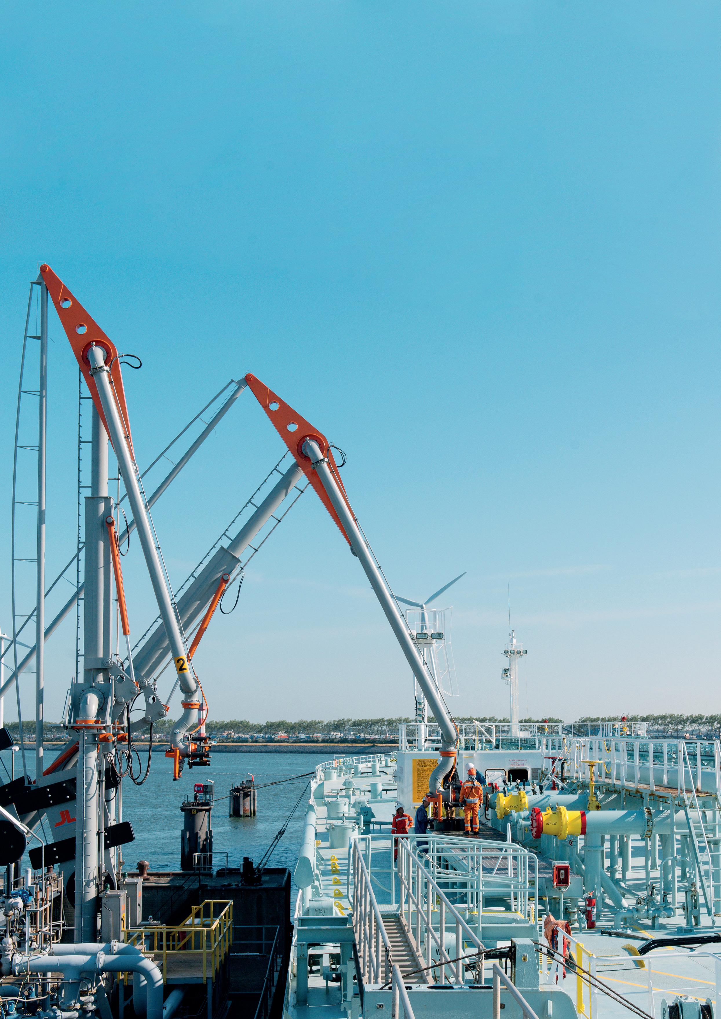
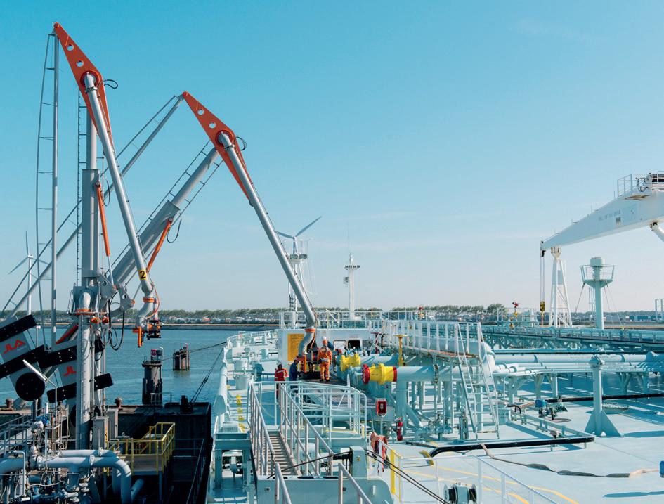
Figure 1. JLA marine loading arms in operation, with asymmetric, self supporting design.
16 Summer 2024
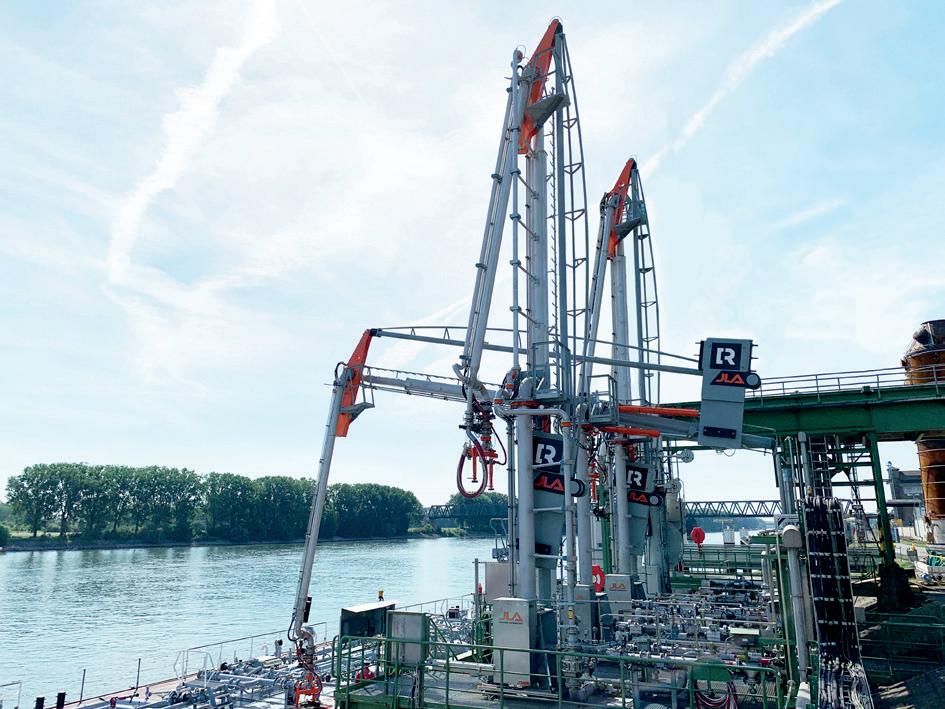
Figure 2. JLA marine loading arms in operation for liquid ammonia.
We understand how you need to reduce complexities at your plant.
CLEAN PROCESS + CLEAR
You strengthen your plant’s safety, productivity and availability with innovations and resources.

Endress+Hauser helps you to improve your processes:
• With the largest portfolio of safety instruments that comply with international regulations
• With applied technologies and people who have extensive industry application know-how
• With access to accurate and traceable information
Do you want to learn more?
www.endress.com/oil-gas
PROGRESS
way, the ERC can never be initiated before the valves are closed.
The QC/DC accelerates and improves the ergonomics at connection and disconnection of the loading to and from the ship.
To keep ammonia in liquid phase, it is cooled down to approximately -33°C. This means the flanges will be cold and will likely contain ice on the connection flanges. As such, it will be very difficult to disconnect with conventional bolted flanges. Therefore, a QC/DC is highly recommended for liquid ammonia applications.
The QC/DC is mounted at the end of the loading arm to connect to the ship manifold. They can be either manually, hydraulically or electrically operated.
When handling dangerous products it is strongly recommended to apply an electrically operated QC/DC that can reconnect within seconds after disconnection is initiated, without the operator being near the flange opening itself. In this way, the loading arm can reconnect to the ship flange in a safe manner when the operator notices the loading arm still contains product or pressure.
QC/DC with two-way-safety-connection is the safest solution for both the environment and the operator.
Safe balancing
Another important aspect of the loading arm is its balancing mechanism. It is fundamental for any marine loading arm to be completely balanced at all positions. When it comes to balancing, there are two options: cable balancing with a wire rope system or balancing through a rigid link.
In the past, JLA Loading Technology has built cable balanced loading arms. However, the company has found that a rigid balancing link design eliminates the major disadvantages of steel cable balanced loading arms.
Pantograph cables used for balancing with steel cables need to be lubricated frequently and they tend to elongate over time as they are connected to the counterweight of the loading arm pulling onto the cable. This elongation requires continuous tensioning of the cable as well as adjusting of the balancing. If this is not carried out frequently, it will cause stress onto the loading arm, resulting in it wearing down more quickly, which shortens
its lifespan. In comparison, the rigid balancing link does not require lubrication nor balancing adjustment. The cables are also more sensitive to corrosion than the rigid link. When the cables are not properly maintained, and occasionally replaced, it can become a serious risk. Accidents are possible, and the cables could snap, causing the loading arm to collapse.
Maximum lifetime, minimum maintenance
The life time and reliability of marine loading arms heavily depends on the quality and durability of their components. Swivel joints, in particular, play a critical role in facilitating the rotation between connected pipe spools, allowing for smooth and efficient operations.
To withstand the stresses and loads encountered during loading and unloading operations, swivel joints must exhibit exceptional durability and resistance to wear. JLA Loading Technology addresses these requirements by utilising cartridge-type ball races made from fully hardened steel, ensuring maximum hardness and minimal brinelling over time. This design not only enhances the longevity of swivel joints but also facilitates easier maintenance, minimising downtime and operational disruptions. By using cartridge ball races, welding is not required and fully hardened material can be applied. When comparing this to conventional swivel joints made out of welded ball races, this hardness ensures stronger swivel joints with longer life times. An additional advantage of this design is that when the ball races eventually wear down, they can be replaced without the need for cutting off the male part of the swivel joints and welding new ones.
Case studies
JLA has been awarded a contract to supply marine loading arms for importing green ammonia to power the NEOM city development in Saudi Arabia with hydrogen. These loading arms, equipped with ERS and QC/DC, offer cutting-edge technology for handling renewable energy carriers safely and efficiently. These loading arms will also be supplied in JLA’s asymmetric and self-supporting design with six swivel joints, ensuring minimum leakage points.
Carbon capture and storage is another interesting solution that is contributing to the energy transition. The Northern Lights project in Scandinavia is an example of one such innovative project. JLA recently secured an order for a 10 in. marine loading arm for liquefied carbon dioxide (L-CO2), which can be transported in larger volumes in ships and transported to the gas fields. The loading arm will load the collected L-CO2 from a wood fibre factory in Denmark and transport it through the network of the Northern Lights project to be stored in an underground gas field in the North Sea.
Conclusion
To create a safe transportation network for liquid ammonia and L-CO2, next generation loading equipment is required that offers efficient loading operations with improved operator ergonomics. Minimal maintenance increases the reliability of these loading systems.
18 Summer 2024
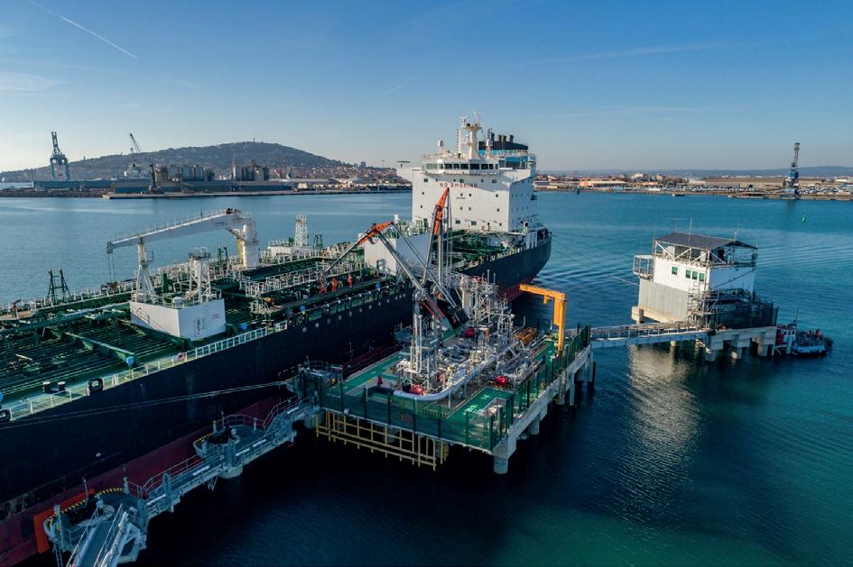
Figure 3. A HydroTec marine loading arm in operation with six characteristic swivel joints with replaceable cartridge fully hardened ball races.
OPTIMIZE TANK LIFECYCLE MANAGEMENT
E²G | The Equity Engineering Group, Inc. provides world-class engineering support for storage tank owners & operators. Our team of experts leverages design, inspection, fitness-forservice, and advanced analysis experience to solve problems both big and small.
We help you ensure safety, manage risk, and maintain profitability throughout your tank’s lifecycle.
FITNESS-FOR-SERVICE (FFS)
DAMAGE MECHANISMS ASSESSMENTS
RISK-BASED INSPECTION (RBI)
Corrosion & Metal Loss
⊲ Shell Distortions
⊲ Foundation Settlement
Structural Concerns
Overpressure & Overfill
Hydrostatic Test Exemption
ENGINEERING PRACTICES (EEP s )
E 2 G SOFTWARE EQUITY
⊲
⊲
⊲
⊲
WE SOLVE PROBLEMS
SAFETY. RELIABILITY. INTEGRITY. VISIT CONTACT OUR TEAM www.E2G.com Sales@E2G.com TECHNOLOGY FORWARD P: +1.216.283.9519 © 2024 E²G | The Equity Engineering Group, Inc.

20 Summer 2024

Daniel Hoy, Endress+Hauser, details how dependable factory calibration can save time during commissioning and provide improved accuracy assurance.
Since the dawn of recorded human history, trade has been an essential part of the social contract, and every fair exchange depends on mutually agreed and fulfilled measures of goods. Naturally, companies and authorities have established standards over time to simplify and expedite the agreement of these measures.
In modern process industries, especially in the custody transfer of petroleum goods, weights and measures play a fundamental role for ensuring the accurate transaction of money and products. Instruments quantify conditions in all controlled applications, and measurement accuracy directly impacts revenue streams, product quality, and operational safety.
While the first modern legislative enforcements for weights and measures were institutionalised by local government decrees, they are now upheld in the process industries by well-known metrological standards based on international studies and proven principles.
Weights and measures in custody transfer
All instruments, even the most accurate, exhibit a certain degree of measurement error, which is typically the difference between the measured value and a reference value.
The tank gauging market places strict requirements on the accuracy of custody transfer level measurement. Standards such as OIML R85, API 3.1B, and ISO4266 each define the required field accuracy in addition to required calibration specifications. For example, OIML R85 compliance requires field verification within +/- 4 mm to manual dipping with an approved tape on top of the tank in which the gauge is installed. However, the same instrument must have an accuracy of +/- 1 mm
Summer 2024 21
against a reference in a controlled environment, such as a factory test rig. The use of a verified and calibrated laser measurement device with a 1 μ m resolution is typically used for this initial verification.
Following OIML recommendations, the initial verification of measuring devices must be performed under reference conditions and at least 10 measuring points must be recorded, evenly distributed over the measuring range.
Calibration overview
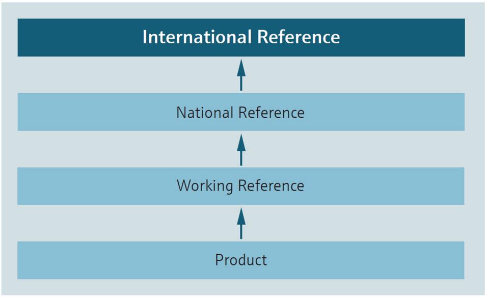
In short, calibration is a process of establishing a relationship between a quantitative measurement and a known reference with the goal of determining measurement errors of a given device, referred to as the unit under test (UUT). Once the measurement errors are known, a UUT can be used as a reference to calibrate other instruments, and master metre proving is a common example of this practice. This calibration chain must always be traced back to national or international primary references to ensure metrological traceability (Figure 1).
In most industrial facilities, instrument calibration is required prior to operation. This means it must be carried out either in the factory before delivery, or in the field after installation. Reliable calibration is critical for long-term process reliability, equipment condition,

minimising maintenance requirements, and ensuring the highest product quality or metering accuracy – so it is important to choose the best method for initial calibration.
Factory calibration benefits
Factory calibration can save end users a lot of time spent on complex and cumbersome field calibration procedures – which can sometimes take up to several days in large tank gauging applications – and it also provides carefully documented calibration records. Additionally, factory calibration is much more accurate than field calibration because the environment is carefully controlled to minimise interference from external factors. Greater accuracy leads to improved automation system performance due to better data on which to base operational decisions throughout a product’s lifecycle.
For these and other reasons, users typically prefer factory over manual field calibration. With continuous level sensors for tank farm and custody transfer metering applications, historic limitations have restrained factory calibration capabilities. However, modern technological innovations are expanding the calibration boundaries for both the radar and servo level instrumentation typically deployed in these settings.
Microscopic adherence to the reference standard and tight regulation of environmental conditions are two of the most critical components in ensuring the accuracy and consistency of factory calibration settings, from one test to the next. Variables such as ambient temperature, humidity, pressure, vibration, and electromagnetic interference all impact instrument measurements, so these and other factors must be carefully controlled.
Radar level calibration
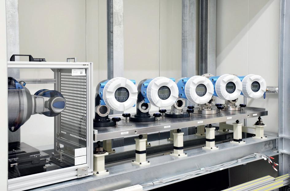
Endress+Hauser’s radar level calibration rig at its production facility in Maulburg, Germany, for instance, is located in a basement with floor and ceiling controls to ensure constant ambient conditions. The floor is also suspended to reduce residual vibrations.
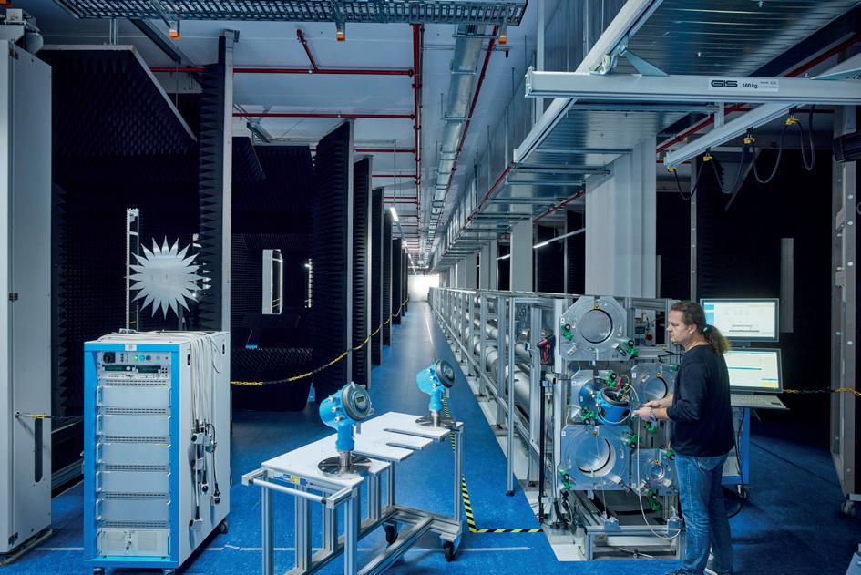 Figure 2. Endress+Hauser’s 50 m free space (left) and stilling well (right) radar calibration rigs in Maulburg, Germany.
22 Summer 2024
Figure 1. An instrument’s calibration traceability to a reference standard ensures calibration validity.
Controlling these and other variables reduces system uncertainties during calibration.
Non-contact radar technology offers a flexible level measurement solution for many applications – especially tank gauging – even in the presence of extreme pressures, temperatures, or gaseous vapours. Radar level sensors emit high-frequency radar pulses that are reflected by the surface of the medium due to the difference in the relative dielectric to air. The reflected radar pulse’s time-of-flight is directly proportional to the distance travelled, and in turn is used to calculate the level based on known tank geometries.
Modern large-scale radar calibration rigs essentially consist of a high-resolution laser, a two-sided reflector, and the level UUT, as well as components for controlling the ambient environment.
The facility in Maulburg has four calibration rigs, each of which is suitable for different radar level technologies and application requirements (Table 1, Figure 2).
After the UUT has been carefully placed at a defined distance ( D ) from the laser, the reflector is iteratively moved to various positions between the laser and radar level instrument.
The measurement error ( E ) at each point during the test is recorded as E = D - A - k - B, where A is the distance from the laser to the reflector, k is the width of the reflector, and B is the measured distance between the reflector and the UUT (Figure 3).
The error values are documented in a factory
calibration report – depending on application, industry, and end user requirements – and the instrument is accepted for service and shipped to the purchaser.
Servo level calibration
Servo sensors are another commonly deployed level instrument in tank farms for the precise measurement of petrochemical volumes in custody transfer and inventory control applications. A servo level gauge consists of a small, buoyant displacer that is held on the surface of a liquid medium by a servomotor. The displacer is suspended on a measuring wire that is wound onto a finely grooved drum housing, and as the
Table 1. Endress+Hauser’s Maulburg production facility calibration rigs for different applications and instrument types
3 Stilling well radar (Figure 2)
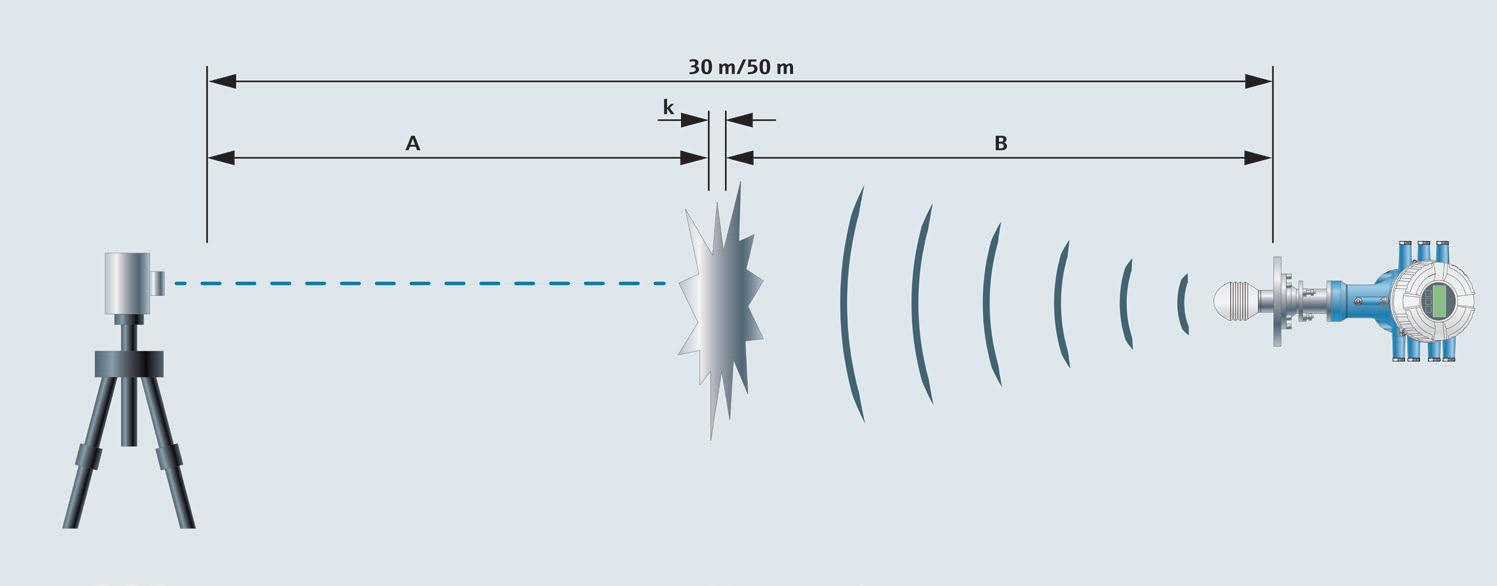
Figure 3. In a factory calibration rig, a two-sided reflector is moved iteratively between a high-precision laser and the UUT, which are placed at a known and uniform distance apart. The measurement error is then calculated at each interval of at least 10 test distances to assess the instrument’s accuracy before declaring it fit for service.
Calibration rig Verified technology Calibration range Archived device accuracy Application 1 Free space radar
50 m 0.5 mm Custody transfer or inventory control 2 Free space radar 30 m 0.5 mm Custody transfer
inventory control
50 m 0.5 mm Custody
wave radar 24 m 2 mm Inventory control
(Figure 2)
or
transfer or inventory control 4 Guided
Summer 2024 23
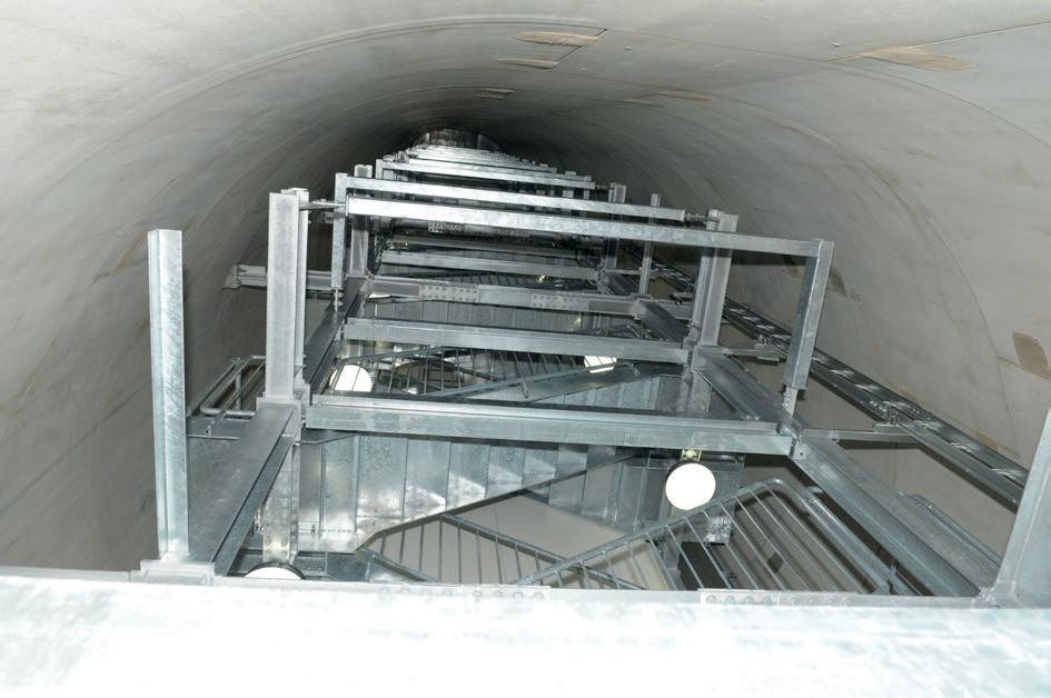
Figure 4. Endress+Hauser built the world’s first 40 m servo calibration tower (left), tunnelling deep below the surface (right) in Yamanashi, Japan, to provide stable ambient conditions.
medium surface level fluctuates and the displacer bobs up or down, the torque in the motor’s magnetic coupling varies. The servo motor then adjusts its position until the net torque is restored to the value prior to the level change. This position adjustment corresponds to a change in the liquid level.
In 2014, Endress+Hauser unveiled the world’s first 40 m high calibration tower (Figure 4) for servo level gauges at its production facility in Yamanashi, Japan. The tower rises 10 m above the surface and sinks down 30 m below grade. This provides stringent control over ambient conditions that – if left unchecked – can interfere with calibration.
A servo calibration tower contains a liquid bath whose level changes during calibration. Like a radar calibration rig, it also uses a high-resolution laser, which is aimed at a reflector on the surface of the liquid. This measured distance is then compared to the level measurement of the servo UUT. The measurement error is recorded as E = C + B - A - D , where C is the distance between the laser and reflector, B is the reflector width above the surface of the medium, A is the vertical distance between the laser and servo’s zero-point, and D is the level measurement of the UUT (Figure 5).
Only recently have construction, testing, and climate control technologies enabled the precise conditions required for this type of high-accuracy premium calibration rig, which is considered the de facto test for assessing device accuracy. The ISO/IEC 17025 certificate empowers operators of these rigs to provide precise,
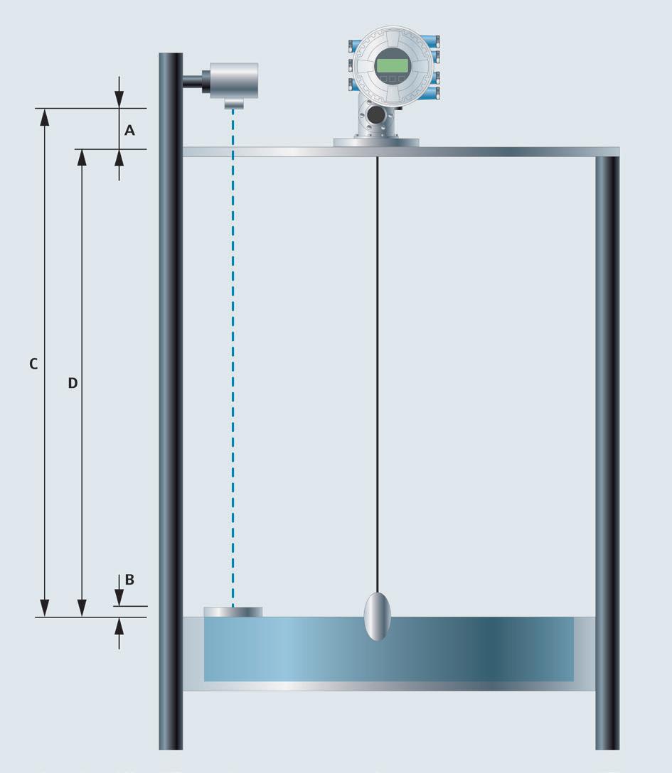
Figure 5. With a factory servo level calibration rig, a laser beam is pointed at a reflector which is juxtaposed by the UUT, and the measured distances between the two are compared to assess the servo level gauge accuracy.
accredited, and traceable calibrations for servo gauges used in tank farms and other level-sensing applications around the world. Subsequently eliminating the need for cumbersome and less accurate field calibration before the instruments are put into operation.
Tank farm expansion
As cities expand, the value of land increases. A tank farm at the port of Antwerp, Belgium was suffering from capacity constraints, but building additional tanks was not an option because it could not expand its footprint. Instead, the company opted to replace several of its tanks with taller storage vessels. However, the target height of 35 m was, until recently, outside the range of factory calibration capabilities. This slowed down efforts to increase the size due to the difficult and time-consuming field calibrations that would be required.
Endress+Hauser placed its 50 m radar and 40 m servo level calibration rigs in service to provide accurate and long-term calibration certification for the level instruments used to metre petrochemical transfers. With the significant amounts of liquid product in each tank, every millimetre counts, so installing accurate and reliable instrumentation was of the utmost priority.
Additionally, the tank farm used Endress+Hauser’s tank gauging software to:
n Implement and monitor key performance indicators (KPIs).
n Automatically create and update electronic reports.
n Increase operational efficiency and reduce the use of paper.
n Increase loading and offloading volumetric certainty.
n Provide complete transaction traceability.
With these advantages, the tank farm was able to simultaneously increase and improve measurement certainty, reducing waste and increasing profits. Furthermore, the company utilised the new KPIs and reports to manage business procedures more efficiently.
Modern calibration rigs increase process reliability
Reliable instruments that can be traced back to accurate and trustworthy references are the measures of all things in modern industry. In highly competitive markets, measurement reliability and controlled processes are vital as they provide companies with the tools to remain viable.
High-precision calibration rigs enable processors to use reliable instrumentation from the factory, eliminating the need for field calibration during commissioning, and providing a higher level of confidence throughout the operational lifecycles. Paired with other advances, such as analytical reporting software and smart device diagnostics, plant personnel waste less time worrying about measurement errors and lost revenue and instead use it for business and process optimisation.
24 Summer 2024

Håkan Enarsson, Emerson, USA, explains the advantages non-contacting radar level gauges provide when measuring the level of used cooking oils for inventory management and overfill prevention purposes.
The use of used cooking oils (UCOs) as a biodiesel feedstock is increasing significantly. UCOs are oils and fats that have been used for cooking or frying in the food processing industry, restaurants, fast food outlets, and households. A comprehensive 2022 report by research company Research and Markets predicts that the global UCOs market will grow from US$6 billion in 2021 to US$8.8 billion by 2027.¹
Summer 2024 25
In Europe, the ongoing increase in demand for UCOs has been significantly boosted by the revision of the EU’s Renewable Energy Directive, which was adopted by the European Parliament in December 2018. It is widely acknowledged that biofuels provide a valuable means of reducing CO2 emissions in the road transport, shipping, and aviation sectors. However, because of its concerns over the impact of land use change and deforestation, the EU wants

Figure 1. Used cooking oils, from the food processing industry, restaurants, fast food outlets, and households, are increasingly being used as a biodiesel feedstock.
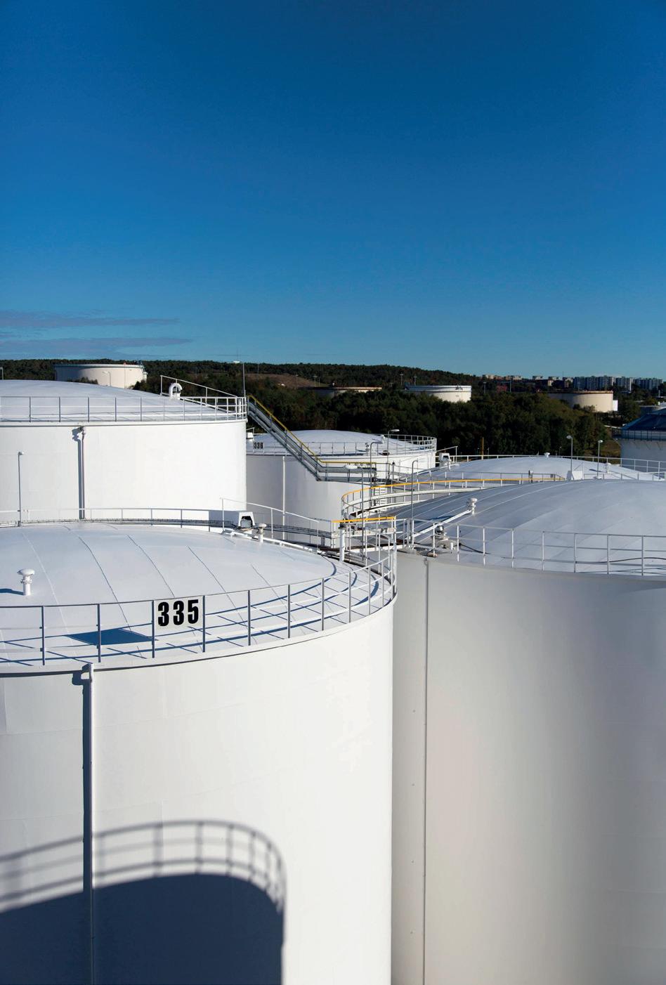
Figure 2. Adding UCOs to the range of bulk liquids that facilities handle means that it is vital, for both inventory management and overfill prevention purposes, to ensure that storage tanks are monitored by reliable tank gauging systems.
to stop the growth of biofuels production from food crops and phase out production from palm oil. It has stated in its revised directive that advanced biofuels to provide renewable energy in transport should instead be produced from a list of preferred feedstocks that includes UCOs.
Tank gauging systems
The increasing use of UCOs as a biodiesel feedstock has in turn created a requirement for greater storage capacity for the product, with a growing number of storage terminal owners and operators adding UCOs to the range of liquids that their facilities handle. It is vital for both inventory management and overfill prevention purposes to ensure that these tanks are monitored by reliable tank gauging systems, in compliance with the relevant global safety standards. These systems incorporate instruments measuring level, temperature and pressure, as well as inventory management software to enable terminals to be operated much closer to capacity, which can significantly increase efficiency and profitability.
Mechanical level measurement technology
In the tank storage and terminals industry, level measurements have often traditionally been performed using mechanical technology, such as float or servo gauges. In the former method, a large float inside a tank is connected to a spring motor and a mechanical numeric indicator outside the tank through a pulley system. For remote monitoring, float gauges can be equipped with a transmitter that provides level measurements to the control room. In the servo method, a small displacer, which has buoyancy but does not float on the liquid, is suspended by a thin wire that is connected to a servo gauge on top of the tank. A weighing system in the gauge senses the tension in the wire. Signals from the weighing mechanism control an electric motor in the servo unit and make the displacer follow the liquid level movements. An electronic transmitter sends the level information to the control room.
Although these mechanical devices are still widely used in the industry, they are not suitable for UCO applications. This is because during cold weather, UCOs stored in unheated tanks are prone to crystallisation, which causes a layer of solid material and foam to form on the surface of the liquid. Solidified product can contaminate mechanical equipment and affect the device’s accuracy, and there is also the potential for the gauges to get stuck. In addition, mechanical gauges have many moving parts that will require maintenance and repair over their lifetime. This then involves personnel having to climb tanks to perform maintenance tasks, placing them at risk of a safety incident. It should also be noted that UCOs have a number of extremely unpleasant sensory properties, which is a further reason for wishing to keep workers away from tanks as much as possible.
Radar level gauges
Because mechanical gauges are an unsuitable technology for measuring the level of UCOs, owners and operators
26 Summer 2024
RELIABLE CONSISTENT RESULTS
Proven, advanced formulations ideal for your processes, industry, and applications. More and better choices in heat transfer fluids based on our over 35 years experience.
www.paratherm.com
2009 Renaissance Blvd., King of Prussia, PA 19046 USA Int’l: +1 610-941-4900 Fax: +1 610-941-9191
adding UCOs to their storage terminals may need to update their tank gauging systems and replace legacy mechanical devices with automated continuous level measurement technology. The modern approach to tank gauging involves the use of top-down, non-contacting radar level gauges to provide extremely accurate measurements. Some radar devices, such as the RosemountTM 5900 Series Radar Level Gauge, use frequency modulated continuous wave (FMCW) technology to optimise their radar signal strength and produce more robust measurements. The result is level measurement accuracy to within 0.5 mm (0.020 in.) and a 180% reduction in volume uncertainty when compared with measurement methods, such as float or servo gauges. Because they are not in contact with the material being measured, the measurement accuracy of these devices is not affected by crystallisation or contamination, making them ideal for UCO applications.
Importantly, radar level gauges can be particularly reliable. Their design minimises maintenance requirements because they have no moving parts, and the mean time between failures for their critical parts is measured in decades. With no regular maintenance or recalibration being required, the availability of radar level gauges is close to 100% during their long lifespan. This not only helps to ensure that the operational availability of tanks and vessels is maximised, but also increases safety by minimising the need for workers to attend tanks to perform maintenance tasks.
Diverse and identical separation
Storage terminal owners and operators may choose to switch the products stored in some of their tanks. Bulk tanks that may be used to store hazardous liquids not only need to incorporate technology to perform tank gauging but also require an overfill prevention system, in order to prevent spills that could have serious consequences. There is a common misconception that the level measurement instrumentation used in the tank gauging system and the overfill prevention system must be based on different technologies – for example, a combination of radar and servo gauges. This is typically referred to as diverse separation. However, diverse separation is not a requirement of the International Electrotechnical Commission’s global functional safety standard IEC 61511. The standard states that it is legitimate to use the same technology for both the tank gauging system and the overfill prevention system, which is known as identical separation.
While both diverse and identical separation are valid options, diverse separation introduces extra complexity and increases the likelihood of human error by requiring personnel to be trained in installing, configuring and proof-testing two different technologies rather than just one. Anything that can be done to streamline operations and minimise human error is vital in preventing safety incidents and optimising terminal throughput. Standardising on a single technology also helps to simplify maintenance and reduce spare part requirements.
Two-in-one technology
Therefore, radar level gauges can legitimately be used in both the tank gauging system and the overfill prevention system for bulk tanks that can be used to store UCOs. However, some tanks that are being switched from other liquids to UCO storage could have practical limitations that make upgrades with two separate level gauges cost-prohibitive. For example, an additional tank opening might not be available, and the necessary modifications would require the tank to be taken out of service, thereby resulting in additional costs and reduced throughput.
Using a radar level gauge solves this problem, as it can be supplied with two separate and independent electrical units in a single housing. This enables a single device to be used for both tank gauging and separate overfill prevention purposes, when connected with its cables separated in different cable trays and with separate power sources. This option, which can be potentially verified by a third-party assessor like Exida® as fulfilling the requirements of IEC 61511, means that just one tank opening is required, thus reducing costs by eliminating the need for major modifications.
Case study: Decal storage terminal, Huelva, Spain
In 2022, Decal – a company providing storage and handling services for oil and petrochemical products in Europe, Central America and South America – began expanding its facilities in the port city of Huelva, Spain, for the handling of products destined for use in biofuels production, including UCOs. The €20 million project includes the construction of 10 new storage tanks and auxiliary installations, expanding the site’s storage capacity by approximately 75 200 m³. The new tanks integrate with ship loading and unloading facilities through the terminal’s three berthing jetties.
Existing tanks at the Huelva terminal were using a mixture of radar and mechanical gauges to provide level measurement, but Decal decided to test various types of technology on its new UCO tanks, to see which would perform best with this challenging product. During winter testing, Emerson supplied a Rosemount 5900S Radar Level Gauge with a parabolic antenna which was found to perform well in the cold temperatures. These non-contacting devices have since been installed as part of the tank gauging system on the facility’s new storage tanks.
Conclusion
The effects of contamination and crystallisation make mechanical gauges unsuitable for performing level measurement in UCO applications. However, the performance of non-contacting radar level gauges is unaffected by the challenging properties of UCOs, and these highly reliable devices have been proven to provide extremely accurate measurements as part of a modern tank gauging system.
Reference
1. ‘Used Cooking Oil Market 2022’, Research and Markets.
28 Summer 2024
Tim Bovard, Owens Corning, USA, examines the main corrosion-related difficulties faced by the tank storage industry as discussed during the recent AMPP Annual Conference and Expo held in New Orleans, Louisiana, US.

The Industrial Internet of Things (IIOT) has ushered in many solutions to improve the performance of storage tanks, terminals, piping systems and other industrial equipment used in the energy sector. Remote monitoring capabilities, predictive maintenance, and enhanced safety and security systems are just a few examples of the advances designed to improve the reliability, safety, and operations of storage tanks and terminals.
Summer 2024 29
Yet despite these technologies, some chronic threats persist when it comes to the optimal performance of industrial assets. Corrosion is a good example of a problem affecting tanks and storage terminals around the globe. Looking at the cost that corrosion under insulation (CUI) imposes on the oil and gas production industry, a study by the Association for Materials Protection and Performance (AMPP) (previously known as NACE) estimated the total annual cost of corrosion to be US$1.372 billion.¹
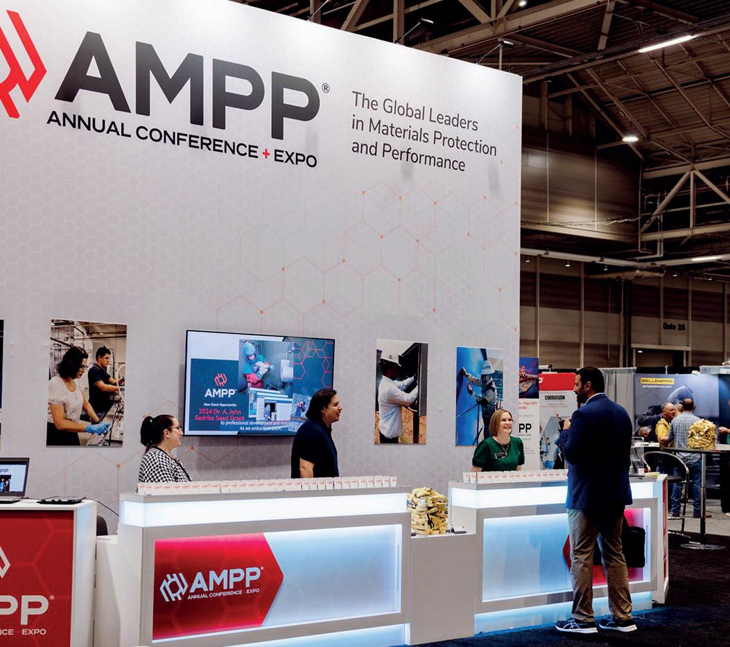
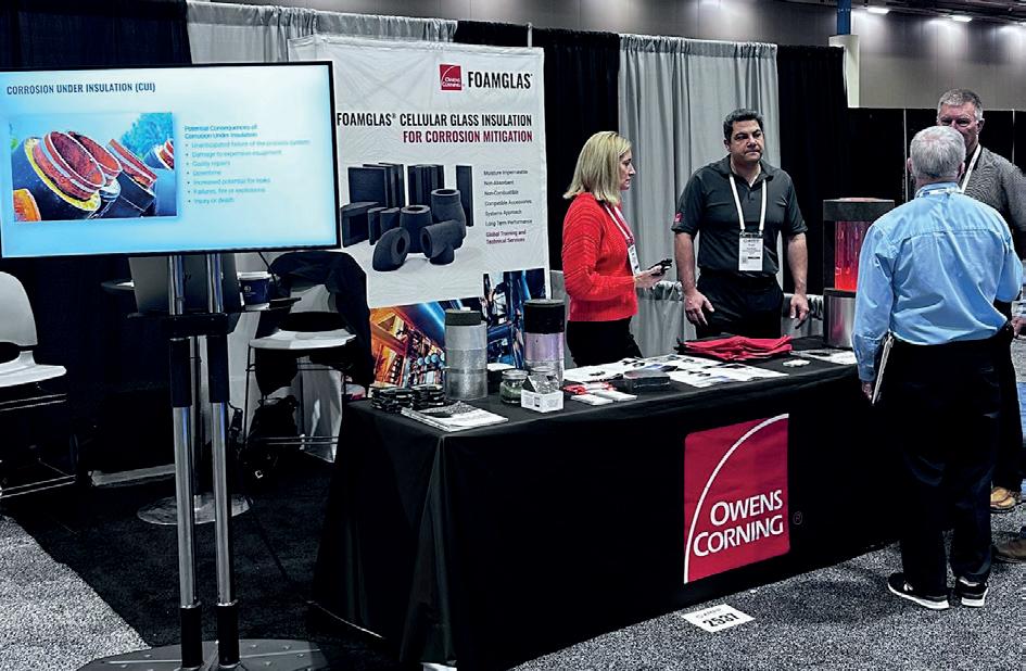
The good news is that materials science, education, and the efforts of industry are helping to mitigate the threat that corrosion presents. Bringing together nearly 6000 people to tackle corrosion topics is bound to result in the sharing of many perspectives about strategies for solving the issue. Exhibiting at the 2024 AMPP Annual Conference and Expo in New Orleans, Louisiana, US, offered a powerful reminder of the ongoing problems corrosion presents for storage tanks and terminals that
house industrial process materials at temperatures ranging from the cryogenic to extreme heat.
Conversations with conference attendees made it clear that CUI remains a significant concern for engineers working in processing environments such as refineries, LNG facilities and chemical plants. Beyond damaging or destroying equipment, and interfering with process materials, corrosion can impose economic costs related to unplanned process shutdowns.
While CUI is not a new threat for industrial equipment and processes, new engineers may not be familiar with practices for defending against corrosion. As seasoned workers retire and new entrants join the industry, it is worth considering that these workers may not have encountered a system failure caused by corrosion. Educating engineers who specialise in insulation systems about real-world situations can help them consider the potential risks during the design stage of an insulating system. Even engineers who have worked in the industry for many years can find it helpful to review best practices that defend against moisture ingress and support the longevity of tanks and terminals. In conversations with engineers at the AMPP Conference and Expo, some best practices for defending against corrosion in tanks and terminals came up repeatedly. Subsequently there were six key takeaways from the show.
Design to manage moisture risk
While corrosive damage can easily be spotted on some areas such as on surface coatings it is more difficult to see when it forms in locations hidden from view. Signs of corrosive damage such as pitting or corrosion-induced stress cracking can be difficult to detect when underneath the insulation. In warmer environments, the formation of ice balls on equipment is a red flag that often indicates corrosion. Because signs of corrosive damage are often hard to detect, it is essential to design insulating systems with a preventative mindset. The presence of moisture is a requirement for corrosion to occur on metal substrates so specifiers should consider the many ways that moisture may infiltrate a system. These paths may include vapour drive pushing moisture through the insulating system, breaches in jacketing, and penetrations or protrusions.
Identify all the weak links
A longstanding flaw in the design of tanks has been designs which focus on one attribute, such as compressive strength, fire resistance or thermal performance without giving adequate thought to water management. Any penetration or breach in jacketing will allow water to access the insulating system and move toward the metal tank surface. Breaches can occur at any location in the tank including the base, walls or roof. Elements such as exterior staircases and entry doors can allow liquid and vapour moisture to infiltrate through the tank walls. Tanks installed on concrete bases atop soil can allow moisture to infiltrate upwards from the ground, pass through the concrete and come into contact with
Figure 1. The 2024 AMPP Annual Conference and Expo convened industry leaders from across the material science sector.
30 Summer 2024
Figure 2. At the AMPP Annual Conference and Expo exhibit hall, Owens Corning engineers shared how non-permeable cellular glass keeps liquid and vapour moisture from entering the insulating system.
www.zwick-armaturen.de
the metal tank bottom. Some tank roof designs allow water to pool at the top of the tank, providing a constant threat of water infiltration. Selecting an impermeable insulating material, such as cellular glass, can keep moisture from accessing entry points throughout the tank design.
Think beyond liquid moisture
When designing an insulating system to withstand moisture, it is vital to defend against vapour as well as liquid moisture. Vapour drive will continually push humid, warmer air toward cooler process vessels. It is worth noting that many LNG and petrochemical sites are located in climates with high humidity and warm ambient temperatures. The contents of storage tanks at LNG and hydrocarbon processing facilities can range from 14˚F to -452˚F (-10˚C to -269˚C). The difference between ambient temperatures and the temperature of cold process material means that tanks need to be protected from vapour drive which can allow ice to form on the outside of tanks.
Beware of permeable insulating materials
When permeable insulation becomes wet or saturated, CUI can develop along with a cascade of other issues. Wet insulation can lead to a loss of process control and reduce energy efficiency. Reduced thermal control can mean that the stored material is no longer at the correct temperature, resulting in boil-off, product loss, interruption of fluid flow or undesired changes in viscosity. An impermeable, non-absorbent insulating material, like cellular glass insulation, can help prevent ingress from water vapour or moisture. Comprised entirely of glass, impermeable cellular glass acts as a barrier to keep liquid and vapour moisture from collecting on metal surfaces. When tested, cellular glass insulation was found to have a moisture absorption rate of less than 0.2% by volume and a water vapour permeability of 0.00 by perm in. (0.00 ng/Pa.sm). Additionally, should an issue lead to a leak of tank contents, the material will not absorb spilled hydrocarbons, which reduces the fire risk and helps improve facility safety.
Design for stability
When designing a tank insulation system to ensure longevity, specifiers should select an insulation that helps mitigate CUI, but other factors should also be considered. Insulation used in tank applications should have a thermal expansion/contraction rate that allows it to consistently protect the tank as it is filled. Metal tanks can contract as they are filled with liquids at cryogenic temperatures and insulating systems need to be designed to support this movement while remaining impermeable to moisture and water vapour. Some insulations shrink more quickly than the tank does at a given temperature. This difference may leave a tank vulnerable to heat gain or moisture penetration and CUI formation as gaps open in the insulation.
Installing an inorganic insulation that has a dimensional change similar to steel at low temperatures like cellular glass insulation avoids shrinkage-caused insulation gaps. By insulating the tank using an impermeable insulating material which has dimensional stability that can accommodate temperature-based changes in tank size, the tank can continue to efficiently maintain the temperature of the contained LNG and be protected from moisture intrusion. At low temperatures, cellular glass insulation has a rate of contraction similar to steel, therefore allowing it to continue protecting the insulated tank during a cool-down period. Additionally, avoiding insulation gaps during cool down helps reduce the possibility of heat gain and supports thermal efficiency.
Educate the industry’s next generation
Reflecting on conversations with attendees at the AMPP Annual Conference and Expo, it is clear that as one generation of engineers retires, preparing the next generation with the knowledge and training to defend against CUI must be a priority. Although the conversations were anecdotal, a common concern was that most engineering students receive little classroom education on industrial insulating systems.
Recognising the need for education, Owens Corning has taken several steps to help ensure knowledge is passed on to the next generation of engineers, installers and inspectors. Educational resources include training centres that provide hands-on teaching using both large and small diametre piping depending on the training needed. Additionally, a team of trainers is available for on-the-jobsite education on the safe and proper handling of products. Currently, theoretical as well as practical hands-on training is available for engineers, contractors and installers. Courses also include an examination of common problems experienced on jobsites and demonstrations on how to prevent or solve these issues.
Conclusion
Throughout the conference, there were a lot of questions about corrosion, corrosion prevention, and how to support the longevity of insulating systems, particularly in the booming energy sector. As the industry continues to meet at in-person gatherings after the disruptions posed by a global pandemic, the opportunity to collaborate and learn from peers is helping to raise awareness of areas where more industry education is needed.
The practical application of materials science coupled with ongoing education and training can help the industry solve persistent challenges, including the threats that corrosion presents to tanks, terminals, and storage vessels around the globe.
Reference
1. 'Oil and Gas Production', AMPP, https://www.ampp.org/ technical-research/what-is-corrosion/corrosion-referencelibrary/oil-gas#:~:text=The%20total%20annual%20cost%20 of,according%20to%20a%20NACE%20study
32 Summer 2024
CDebra Hall, Elementale Enterprises Inc., explores an alternative method used for protecting metal components from corrosion.
orrosion can cause costly and dangerous product leakage from storage tanks and other distribution systems through rust holes. Rust is the symptom of corrosion. It is evident when corrosion has already infected the metal. Even a small rust hole can result in significant product release over time.
Many owners of bulk containers (i.e. above and underground storage tanks) are not even aware of a corrosion problem until it is too late. In a US Environmental Protection Agency (EPA) study, 25% of owners did not know that their tanks were moderately to severely impacted by corrosion.¹
An owner may be able to identify severe corrosion problems easily if it affects fuel flow, but without best management practices and costly visual inspections at regular intervals, an owner may be unable to identify the beginnings of

the problem before the equipment becomes corroded and potentially compromised.
However, solutions are available to help combat corrosion, minimise maintenance, prevent further corrosion, increase plant uptime, and keep product in liquid bulk storage vessels.
Combating corrosion
Corrosion is caused by metals electrochemically reacting to their environment. With moisture, oxygen, electrolytes (i.e. salts or acids), temperature changes and even galvanic reactions from material compatibility – constant corrosion over time on unprotected metal components leads to rust. By the time rust is seen, corrosion is already present and damaging critical components (i.e. piping, swing joints, and flexible connectors).
Summer 2024 33
The pH is an important indicator of the corrosivity of the electrolyte attached to a metal surface. The electrolyte in the vapour space will also impact the degree of corrosion on various alloys. For example, in carbon steel such as a tank, the corrosion rate is relatively low in aqueous solution, around a couple of thousandths of an inch per year, when the pH is
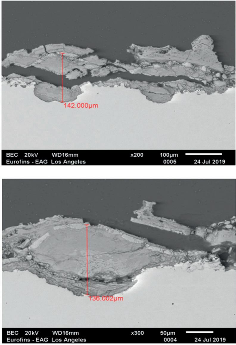
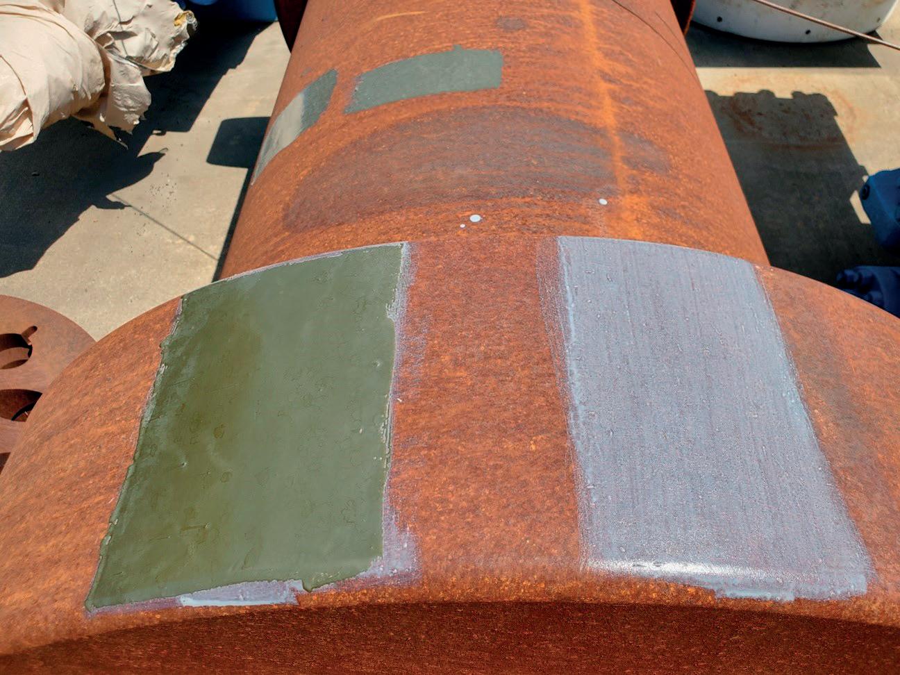
2. MCN primer was applied and left exposed outside for two months. A topcoat was applied (left side) after two months. The other part (right side) remained exposed for comparison. This example is unaffected by UV or outside elements.
between 3 and 9; however, below 3 it dramatically increases, and above 9 the corrosion rate decreases.
In the case of aluminium, the corrosion rate in aqueous solution will increase below 4 and above 8.5.
The actual corrosion rate on a metal will also depend on other factors, mainly the presence or absence of oxygen and contaminants such as chlorides, sulfides, other chemicals, and particulates.
Until recently, the three common methods used for protecting metal components from corrosion were cathodic protection, metal surface finishing (like galvanising), and coatings/barriers to isolate the metal component from the corrosive environment.²
These methods are often costly and maintenance intensive.
Cathodic protection has a high installation cost, requiring a sacrificial metal to be used to allow for the corrosion reaction. In many cases, these sacrificial metals are never replaced, giving a false sense of security while the metal becomes plagued with corrosion.
Using metal surface finishing (i.e. galvanising, anodising, electroplating) is also quite costly. It works on some metals, but not all, and it may require the use of harmful toxins for the process. Additionally, this is typically done for new installations; not for corrosion that is already in the field.
Finally, traditional coatings have been adopted such as paints, epoxies and/or polyurethanes that are low-cost, but must be reapplied often due to their lifespan (sometimes every six months), making the cost of labour and downtime for painting quite expensive. Additionally, many of these products have high toxicity and volatile organic compound (VOC) content, they are prone to UV and heat damage and will crack and peel. These may protect the metal by covering rust, but they do not eliminate corrosion – and re-application of these is regularly needed.
A novel approach is a biodegradable treatment that is absorbed into the metal and neutralises the metal to attack rust and stop corrosion. The Metal Corrosion Neutralisation (MCN) treatment penetrates down to the surface of the metal, separates, and encapsulates the rust for the complete long-term protection of the surface area.
MCN neutralises the metal, continuing to attract water to its surface so that no moisture hits the metal.
With its absorption characteristics, the MCN gets into any pits, is water-based, UL GreenGuard Gold certified, and needs only basic pressure washing preparation on the metal instead of sandblasting and grinding. Figure 1 shows how MCN treatment penetrates through the rust to the bare metal.
Time and curing
The curing time required for the MCN to completely pass through rust to metal substrate in Elementale Enterprises’ tests is four hours.
Nevertheless, a topcoat could be applied when MCN is dry to the touch (10 – 15 minutes in the sun), thus minimising the plant downtime required for application, allowing for the application of product to continue non-stop. The requirement of a topcoat will not affect MCN’s ability to penetrate rust.
On the other hand, if production needs to get back online quickly, MCN is a primer with a long re-coat window which allows scheduling flexibility for application in order to minimise
Figure 1. MCN (dark grey) has penetrated rust (grey) all the way to the white steel (white) – 142 µm deep.
34 Summer 2024
Figure

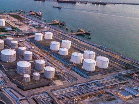
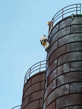
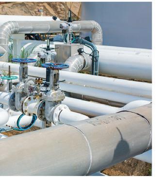
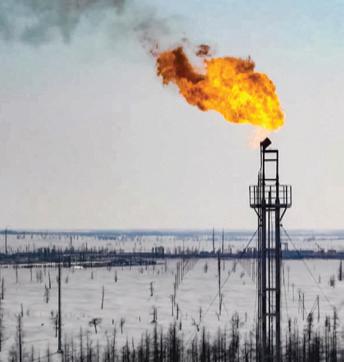
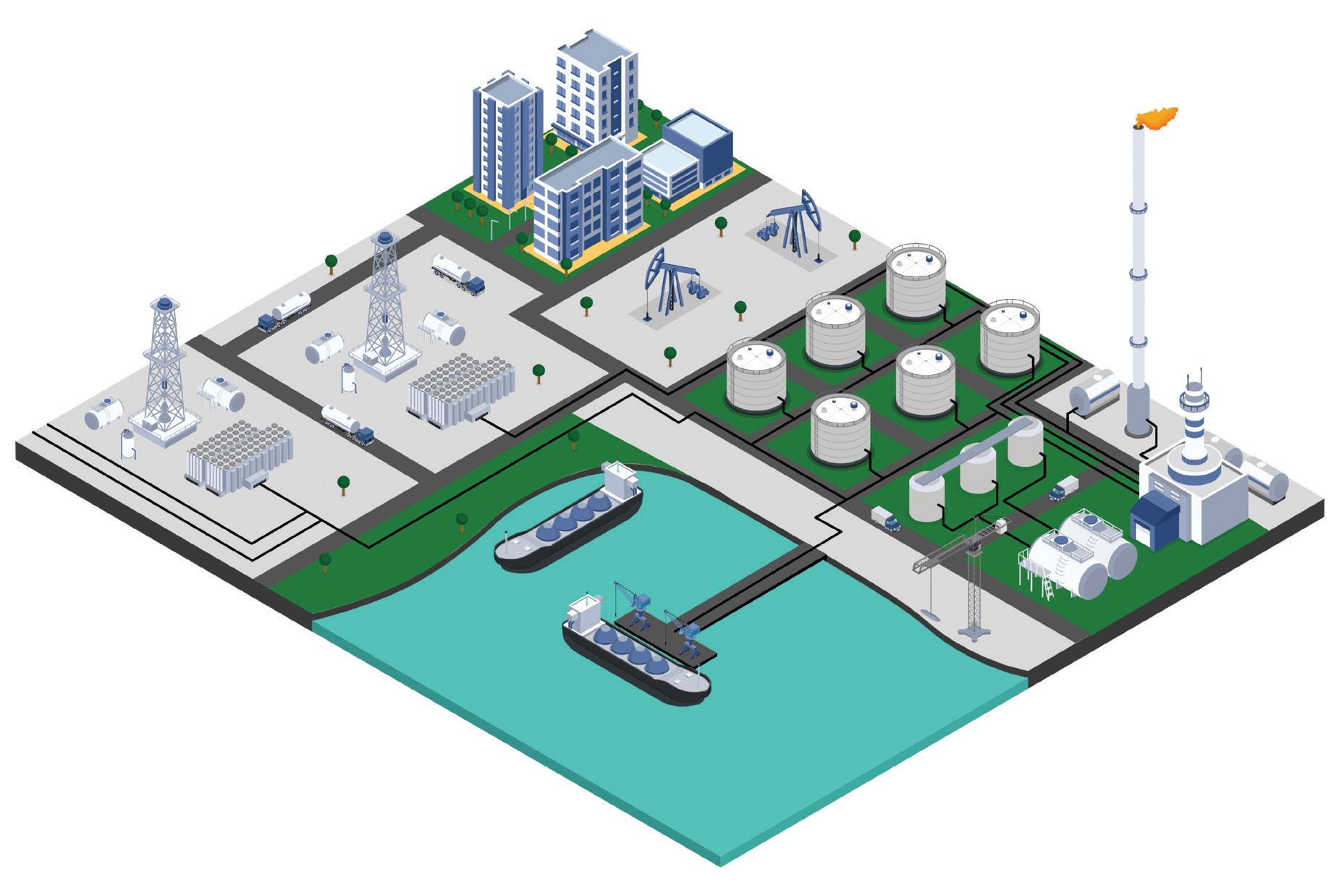

plant downtime. Figure 2 compares an exposed MCN section alongside a section that has a topcoat. This is over a two month span. As evident, the MCN is still intact.
Meeting the rigorous standards
ASTM B117 salt spray test
Salt spray tests have been conducted showing no rust mitigation under the MCN treatment as demonstrated in Figure 3.
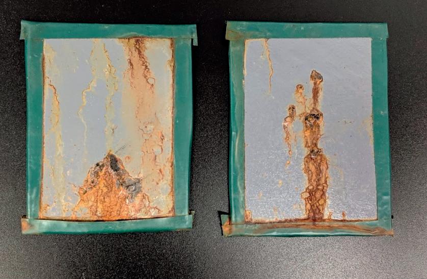
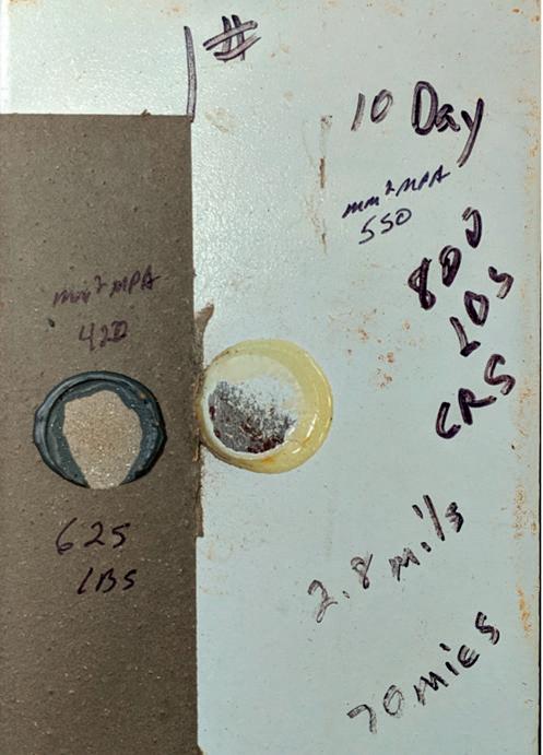
On the left of Figure 3, the scribed panel shows bubbling and rust development in and around the immediate area of scribe (V shape). There is no rust migration under the treatment and no peeling, with the treatment remaining intact.
The right of Figure 3 shows the non-scribed panel with several pinholes cut into the centre area. Taped edges allowed significant rust from uncoated edges to bleed through the tape. The coating showed no failure apart from slight bubbling and rust within areas where pinholes were cut. Furthermore, there was no rust migration under the MCN.
NACE pull tests
It is critical to understand the pull-off strength (commonly referred to as adhesion) of a coating system from metal substrates. This test offers two test protocols. Protocol 1 (test to fracture) determines the greatest perpendicular force (in tension) that a surface area can bear before a plug of material is detached.
The pass/fail criteria for typical coatings is 10 – 20 MPa.³ It is shown in Figure 4 that the pull test for the MCN exceeds 1600 MPa. This was a true test of strength. Since the MCN has penetrated the medium, it cannot be removed.
NACE 232409 pull-off strength (adhesion testing)
2.8 mil, 70 μm:
n 10 day cure: 800 lb/mm².
n 7 day cure: 750 lb/mm2
n 3 day cure: 400 lb/mm².
Conclusion
There are key questions to consider when selecting a rust inhibition programme to prevent leakage and reduce frequent repair and replacement costs, while avoiding costly shutdowns. These include:
n How critical is the presence of corrosion to the product quality?
n How critical is corrosion to causing leakage/spillage of product?
n How often are visual inspections being performed?
n How rapidly does the project need to be completed – to get back onto a production schedule?
n How frequently are salts, chlorides, sulfur and other electrolytes in contact with the metal?
n How frequently is moisture in contact with the metal?
n What are the thermal requirements on the product surface?
n What are the environmental, social and governance goals?
By using an anti-corrosion treatment that penetrates the metal, environmental concerns are minimised, as MCN blocks, neutralises, and attracts moisture for long-term protection in any environment.
Addressing corrosion issues at early stages could reduce repair and replacement costs later, as well as reduce the risk of extremely expensive environmental release clean-up costs.
References
1. 'Investigation of Corrosion-Influencing Factors in Underground Storage Tanks with Diesel Service', US EPA, (July 2016).
2. Release Prevention for Underground Storage Tanks (USTs), US EPA, (22 February 2024).
3. Fletcher (Pull Off) Final (elcometerusa.com), Society of Protective Coatings, (2015).
Figure 3. The treatment (grey) stays intact. Only scribed areas show signs of bubbles and rust at the point of damage.
36 Summer 2024
Figure 4. The industry standard is 10 – 20 MPa, which was achieved after the first two days and exceeded 1600 MPa. when fully cured.
TBrian McHale, Carboline, USA, outlines how an industrial coating crew trialled the use of a remote abrasive blaster during a tank refurbishment.
ank 32001 at SunocoLP’s fuel distribution terminal in Linden, New Jersey, US, is unremarkable in its surroundings. It is 17 m (56 ft) tall and 61.6 m (202 ft) in dia.; one of hundreds just like it along what is known as the Chemical Coast, US. But for all its apparent normalcy, it plays a critical role in the carefully calibrated gasoline distribution network fuelling New York City.
It is just one tank at one terminal, but the compounding consequences of an unplanned outage or, worse still, a failure, cannot be overstated. That is why the outages that are planned must be methodical, purposeful, and ideally brief. Tank 32001 was due for its API 653 inspection in early 2023. The inspection revealed that the interior lining was failing, and a refurbishment was recommended. Strong teamwork, new technology, and sound tank lining material selection combined for a

successful refurbishment despite the owner’s tight deadline.
Scope of work tackles pitting and wormhole corrosion
A visual inspection inside Tank 32001 revealed its interior lining was failing, and pitting and wormhole corrosion was apparent across large areas of the steel. The corrosion was widespread but not severe; inspectors regarded it as normal for its immersion service.
The scope of work for the refurbishment consisted of:
n Decontamination of the substrate via solvent cleaning per SSPC SP-1.
n Abrasive blasting via coal slag media of the interior floor of the tank as well as the lower 2 ft of its shell, including manways and structural steel supports, to SSPC SP-10.
Summer 2024 37
n Application of Carboline’s Phenoline 311 as a holding primer.
n Application of Phenoline Tank Shield FP to fill in and seal areas impacted by pitting.
n Stripe-coating weld seams, corners, and edges with thinned Phenoline Tank Shield.
n Application of Phenoline Tank Shield as the finish coat.
The deadline is always now
Work began in early February 2023, the coldest part of the year in New Jersey. However, because the work was confined to the inside of the tank, the cold temperatures during removal of the lining were less of a concern than if it was done outdoors. Even if the inside of a tank was too cool to apply a lining, contractors usually address this by using heating and dehumidification equipment to improve conditions. This, as well as the specification of low-temperature cure materials, contributes to successful lining installation.
These steps are taken because fuel distributors like SunocoLP always require as quick a turnaround as is feasible. Minimising downtime and returning to service
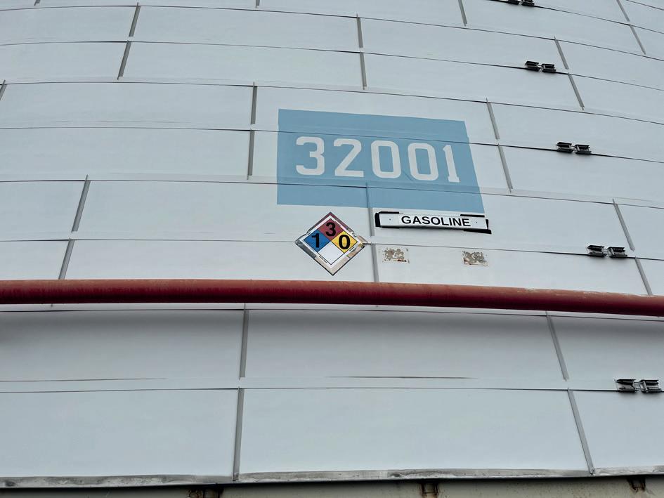
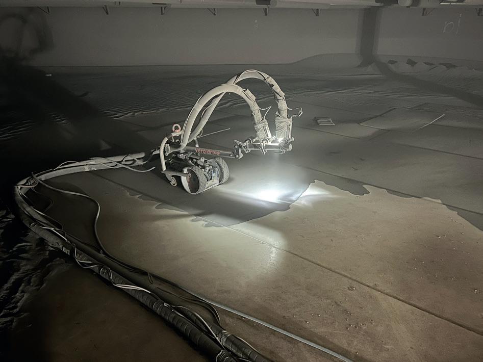
rapidly are necessary to maintain profitability when margins are tight.
Robotic abrasive blaster
A robotic abrasive blast unit is one technology that was considered to help achieve better, safer, and faster results. BlastOne International was invited to bring a VertiDrive M7.2 remote blaster on-site.
The blaster traverses surfaces on four wheels, with a long arm holding three hoses that methodically blast floors, walls, and ceilings due to powerful magnets. With the help of a small camera attached to the unit, a human operator controls the robot’s progress from a safe distance in this case, outside of the tank.
Dave Cushman, the General Manager of West Virginia Paint LLC, was impressed with the performance of the blaster when blasting a new bottom or any surface with consistent film build and adhesion. He said: “When you have the blast rate set correctly, it’s very efficient. And you do eliminate some people from the confined space.” On any job where his crew try something new, Cushman’s hope is to not take any backward steps. “We didn’t take any backward steps on this,” he said. “But the next generation of this is a smarter robot. You’d want a way for an operator to control the robot and also move the hoses, keeping everyone out of the confined space.”
Cushman also envisions future iterations with improved vision and other systems that give operators − and the robots themselves − more and better real-time feedback. For instance, more and higher-fidelity cameras would offer operators a better view of their work area. And more sensitive vision or other sensory systems could help a robot adjust blast rates automatically according to the conditions it observes.
Seeing the future
The safety factor of the robotic remote blaster dramatically improves when dealing with tank assets in far poorer condition than the Sunoco tank in New Jersey. Dave Isaacson, Project Support Manager, BlastOne International, explains: “We just did a job for a major fuel supplier. Their tank was in really poor shape. There were holes in the roof. Instead of putting any people on the roof, we put the robot there. Any safety risk of a person falling, that’s what the robot did.”
Robotic systems such as the VertiDrive M7.2 and its successors are compatible with safety retractable lanyard (SRL) fall protection equipment. Robots should also be designed to be as easy to manoeuvre as they are practical. To provide an example, VertiDrive units are 22 in. wide so that they fit through common 24 in. manways. They can also be handled by two workers, as they weigh just 120 lb (54.4 kg).
A final benefit of using robots, according to Isaacson, is that they do not get tired. Fatigue can lead to safety concerns, as well as inconsistent blast quality. Deploying a robot blaster for large areas that would be monotonous and tiresome for a person frees that individual to manually blast more complex geometries without being exhausted.
Figure 1. Sunoco LP’s gasoline storage Tank 32001 in Linden, New Jersey, US, was refurbished in 2023.
38 Summer 2024
Figure 2. BlastOne International’s remote-controlled VertiDrive M7.2 blasts the bottom of SunocoLP’s Tank 32001.
Strategically located petroleum bulk storage facility. The only deep water platform (64’ operating draft) on the U.S. East Coast
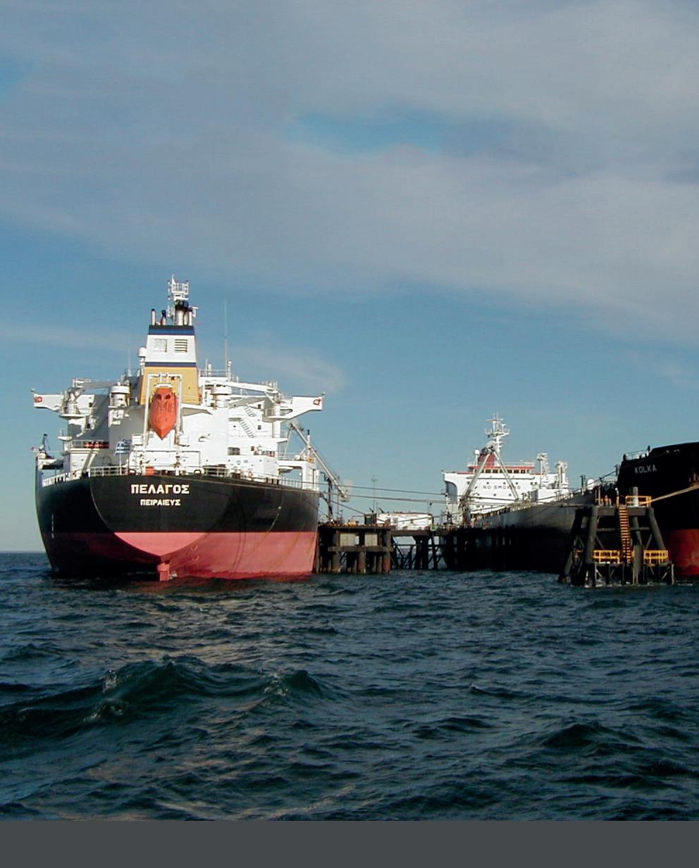
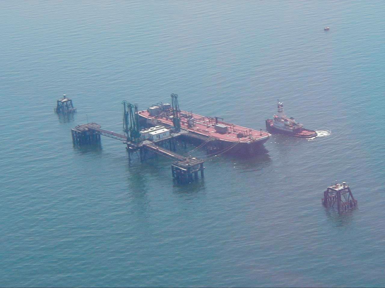
• 20 storage tanks 80 miles East of New York Harbor
• The only deep-water loading/ unloading platform on the U.S. East Coast.
• Total Storage Capacity of 5 Million Barrels
• Easy reloading for distribution of product to U.S., Canada and Europe

(631) 284-2010
www.urtny.com United Riverhead Terminal, Inc.
It is vital that customers understand how to get the most out of the technology. Isaacson explains that it is just as important to help customers change their mindset as it is to change their work processes. “These robots won’t take manpower away from a job site. But throughput will increase. We’ve seen a 50% increase in production compared to manned-only operation,” he said. “It’s all in the mindset. Minds can change when you see how many more tanks you can do in a year.”
Coating crews’ mindsets may be more readily accepting of automation than in the past as filling job vacancies continues to challenge the industry. “We had a recent customer who blasts and paints barges and he’s short on manpower,” Isaacson said. “They saw how well the robot does the undersides of barges. He bought six of them the same day as the trial.”
However, there is still room for improvement. Isaacson said that the VertiDrive unit used in New Jersey worked well, but he knows that further development is needed. Indeed, BlastOne unveiled the new VertiDrive V700 robotic blaster later on in 2023, after the New Jersey project. And further improvements are being researched, such as:
n Teaching robots about specific assets by feeding them past surface preparation and coating or lining application data.
n Improved vision systems and the incorporation of AI to view the condition of a coating and define a programme of work.







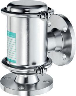
n The ability to map assets and provide more precise schedules.
Isaacson added:“I foresee that the future is definitely going to be automation with robotic painting and blasting.”
Tank 32001 returns to service
Following application of the lining system on Tank 32001 in New Jersey, routine visual inspections, dry film thickness (DFT) tests, holiday tests, and cure tests were conducted. Only minimal touch-ups and repairs were needed owing to sound material selection and good application. It was an efficient job; West Virginia Paint was only on-site for two weeks, a faster delivery than normal. SunocoLP returned Tank 32001 to normal service towards the end of March 2023 – less than eight weeks after taking it offline.
These are noteworthy results considering the project was executed by a team using robotic technology for the first time. It required the committed, collaborative support of a range of stakeholders. The Association of Materials Protection and Performance (AMPP) recognised that when it named the project the winner of its Excellence in Technical Support of Materials Protection Systems award in 2024.
The tank’s new lining is expected to last two decades, protecting the integrity of the tank and its essential contents.


















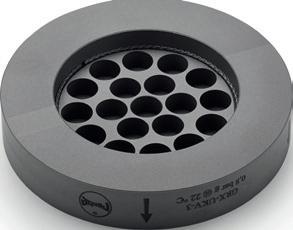



REMBE® Your Specialist for Pressure Relief Solutions © REMBE® | All rights reserved rembe.com
Danny Constantinis, EM&I Group, discusses the use of technology to see through the sludge in tanks.
The demand for world oil shows little sign of abating.¹ Despite a welcome acceleration in the energy transition, fossil fuels will still make up roughly 50% of the world’s energy needs up to 2050. The balance of demand for their use is likely to shift more towards petrochemical feedstock than – as seen previously – transport. Furthermore, upstream investment in 2024 is expected to reach the highest levels since 2015.
This all places a premium on maximising exploration and production assets. The global offshore drilling market has rebounded, and floating hydrocarbon production assets are flooding onto the market. Some assets are old, and some are newbuilds from out of the shipyards; while some are having their lives extended.
All of this exacerbates the challenges for those involved in asset integrity management, and especially for those responsible for inspection.

Many of the former ‘problems’ have been resolved through initiatives such as the Hull Inspection Techniques and Strategy (HITS) Joint Industry Programme (JIP), which is sponsored by the global Floating Energy Forum. This JIP – in which innovators collaborate with regulators, asset owners and operators – is delivering successful outcomes quickly, noting that, ‘just in time’ is frequently ‘just too late’.
In the case of HITS, as an example, the focus has been on reducing and removing the need for diver interventions offshore; and for reducing or removing the need for perilous confined space entry. The focus has also been on enhancing the increasingly large volumes of complex data that is available in order to meet the regulatory requirements. This laser-like focus has enabled the rapid development of technologies. For example, EM&I’s ‘intelligent’, diver-less sea chest blanking to enable valve isolation for replacement and/or repair, and sea chest repairs without diver
Summer 2024 41
intervention, was delivered and approved for operational use within one year. The NoMan Plus® suite of services for assessing the condition of cargo oil tanks – without having to place a human in the tank – has received its first Classification Society Approval with more to follow – all within two years of inception.
Has safety improved as a consequence?
Has the excitement that is driven by the growing demand resulted in enhanced safety for those working in the industry? Are innovative technologies that mitigate safety risk, improve operational effectiveness, and strengthen commercial and financial performance coming to market as quickly as they might? Are they being taken up by operators, owners and regulators? And are the planned environmental benefits reaching their potential for lower emissions?
The answer is no. The bottom line is that people are still being killed or injured in the industry in incidents that are in many ways preventable – and it is simply unacceptable to continue this way, at every level, and not least, at the ethical level.
The good news, though, is that the industry is responding in a positive and effective way, driven principally by the need to mitigate safety risk. Exciting progress is being achieved, especially where there has been collaboration and open mindedness by the key participants.
One such example is how strategies that deal with the inspection of the bottom plating of cargo oil tanks on floating hydrocarbon assets such as FPSOs continue to be sought after.
Bottom plating and the challenge
The hazards associated with FPSO bottom plating and cargo oil tank sludge include the acceleration of corrosion activity within the tanks, which can reduce storage capacity and inhibit the operation of the tank. Additionally, the build-up of flammable or toxic gases from cargo leakage into ballast tanks poses a risk of explosive atmospheres developing in adjacent spaces. High temperatures, humidity, and salt spray in the FPSO environment also contribute to corrosion, potentially compromising the internal integrity of equipment. In brief, bottom plating is a difficult area to use to inspect and assess hull integrity, as shown by Figure 1.
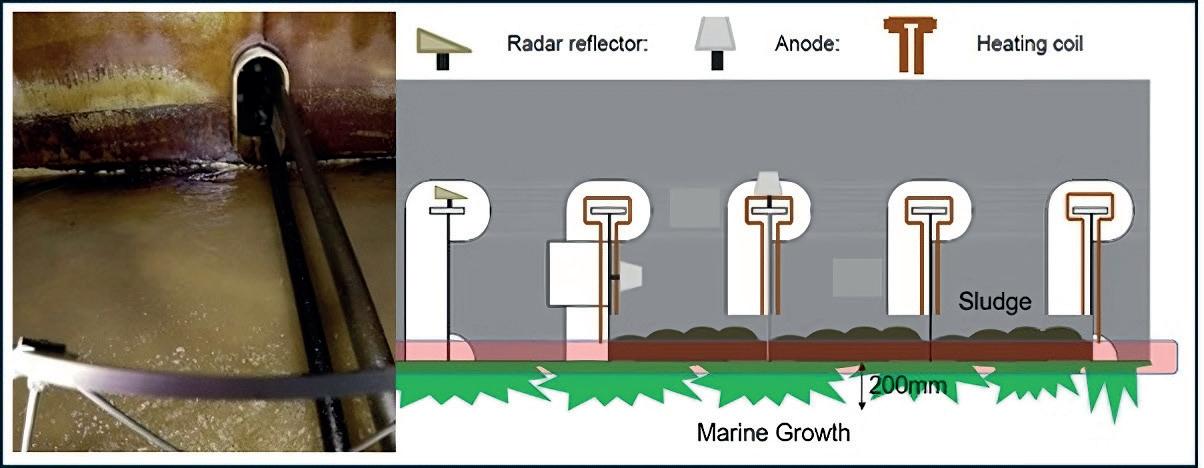
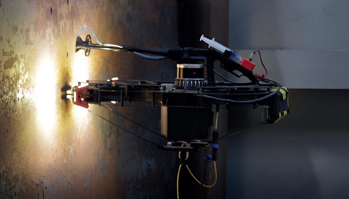
However, top and bottom coatings in the tank help. The bottom coating is to protect against any water that drops out of suspension while being transported or stored prior to offloading, and the coating at the top is to protect against the corrosive effects of inert gas. Some operators have increased the extent of coatings at the top of the tank to include all structure and plating above the normal liquid line and all surfaces of the bottom area, up to 2 m above the bottom. Using the above methods may allow for limited amounts of produced water, or larger amounts for limited times to be stored in cargo tanks without corrosion issues. The amounts, locations, and durations can be tracked to prioritise and determine the extent of required examination of the plating and internal structures of the tanks. Because some water is expected to drop out of suspension, installation of anodes at the bottom of any tank expected to hold produced water is recommended; especially for units that may have water sitting on the bottom for more than three months. In the past, small paint defects have caused accelerated corrosion when exposed to produced water, resulting in localised corrosion in excess of 2 mm/yr. This may be higher if adjacent to stainless steel submerged cargo pumps or heating coils.
Other factors also influence the pace of the build-up of sludge, including the geometry of the tank and its internal tank structure (web frames, stringers and stiffeners); composition of the oil including paraffins (wax), sediment (sand) and viscosity; tank coatings; and the frequency and effectiveness of crude oil washing (COW) and sludge removal performed during operations over the life of the asset. A meaningful close visual inspection of the tank surfaces requires the removal of this build-up of sludge and/or sediment. For existing vessels, this challenge may not be easily overcome due to the high cost and time required to completely retrofit these tanks – so innovative inspection solutions are necessary.
Innovative solutions are coming to the fore
There are a range of innovative solutions either on the market and being adapted to market needs, or that exist but have not
Figure 1. Inspection challenges in cargo oil tanks.
42 Summer 2024
Figure 2. EM&I tethered Advanced Inspection Drone remotely performing ultrasonic gauging, with A Scan, beyond visual line of sight, in a cargo oil tank.
yet been tested under stringent representative conditions. These include:
n Magnetic flux leakage (MFL) can identify the presence of corrosion, pitting, and wall loss; a portable and effective technique.
n Pulsed eddy current (PEC) is an established technique for detecting corrosion. It provides a relative volumetric analysis and is very effective under certain condition.
n An ultrasonic scanning method, an electro magnetic acoustic transducer (EMAT) can inspect through coatings and is not generally affected by pollutants, oxidation, or roughness. EMAT transducers are easy to control and deploy.
n Acoustic resonance technology (ART) is a patented, ultra-wideband acoustic inspection technology for detecting corrosion.
n Magnetic eddy current (MEC) is a variation of eddy current testing which allows the identification of flaws in the volume of thick ferritic steel components, and for detecting corrosion.
Vehicles and inspection delivery technologies abound but are not the panacea; crawlers, robots and remotely operate vehicle (ROV) systems also provide interesting solutions. But it is inevitably the choice and placement of sensors that is key. And central to that choice is understanding the failure modes that are relevant to bottom plating.
EM&I’s NoMan inspection UAV systems are equipped with traditional ultrasonic thickness measurement and A Scan, which provides added assurance that the ultrasonic probe measurements are accurate.
The advent of effective remote inspection technologies is a boost. EM&I has found that development of its Onshore Command Centres (OCC) to facilitate the remote piloting of ROVs offshore in real time has provided the opportunity to extend that technology to its inspection UAVs. This ensures that the delivery of real time insightful imagery from an inspection UAV to whoever needs it onshore is a very real prospect in the near future. But there is some way to go before the UAV is able to deliver a suitable sensor to map the bottom plating. As such, innovators continue to search for a relevant solution.
Conclusion
The inspection of the bottom plating of FPSOs presents significant challenges that impact both safety and operational efficiency. Better design and the swift adoption of innovative diver-less inspection techniques and strategies that minimise human entry into confined spaces, reducing the need for tank cleaning prior to inspections, will ultimately enhance the safety and cost-effectiveness of FPSO integrity.
Reference
1. 'Oil Market Report', International Energy Agency (IEA), (14 December 2023).
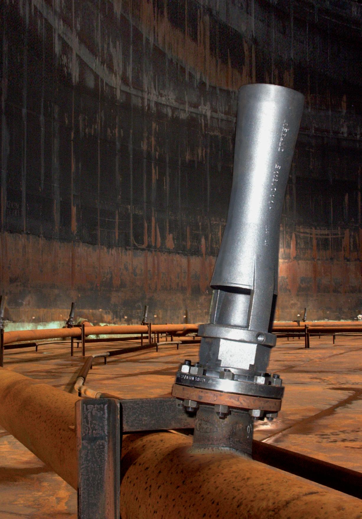
GEA Jet Mixer Systems for tank mixing & blending.
Ideally arranged, the proper amount of Jet Mixers produces a three-dimensional flow that mixes the entire contents without creating a rotating motion in the tank. Delivering high efficiency, operational safety, resistance to fouling and little wear & tear thanks to its simple and robust construction

Download our catalog.




VIRTUAL CONFERENCE 5 SEPTEMBER 2024 Register for free
Dave Godfrey, Rotork, UK, outlines how an effective maintenance plan can reduce downtime, increase profitability and improve safety at tank farms.
Flow control is critical in allowing tanks and terminals to operate efficiently and safely. Effective flow control can reduce emissions, ensure safety, and improve efficiency and yield; irrespective of the application.
Poor flow control maintenance can lead to operational disruption, so keeping flow control equipment such as actuators in peak condition is critical. Inefficient equipment will increase the potential for faults that may incur disastrous environmental and financial costs. Failure of the key equipment that keeps a site running can result in reduced productivity, poor performance, and a drop in quality. Unintended downtime is the most serious consequence of ineffective maintenance.
For long-term reliability and viability, managing flow control equipment effectively is crucial. The ultimate aim is to increase uptime and optimise the required maintenance. Taking equipment out of operation is costly, in addition to the cost of parts and labour. Insufficient maintenance increases the risk of breakdowns, leading to yield loss,

environmental damage, and potential health and safety hazards. One effective solution to preventing this is on-site maintenance. This approach allows crucial servicing to be performed without the need for a plant shutdown.
Which maintenance plan to choose?
An effective and holistic site service programme increases the dependability of site assets. The programme must be accessible, provide value for money, and be customisable enough to cater to different business needs. A potential offering must ensure that the most appropriate response is provided based on the criticality of the application.
A tiered approach to maintenance, like Rotork’s Reliability Services programme, provides a tailored package depending on the level of cover required for site assets. The customisable nature of a service programme like this helps customers balance the risk of downtime vs cost.
Additionally, it is important that there are a variety of optional extras to fit the customers’ needs. Having this type of
Summer 2024 45
flexibility can improve a site’s overall performance. Service programmes of this kind provide a set cost to operators, allowing for the easy management of budgets.
Preventative maintenance, such as regular check-ups, replacing consumable parts, and calibration, minimises the risks of sudden equipment breakdowns while prolonging its lifespan.
Why select intelligent electric actuators?
Intelligent electric actuators are often the flow control equipment of choice because of their reliability, efficiency, precision, ease of use, and ability to capture historical data. They are often used in oil and gas applications like tank farms. In these environments, isolating actuators are used for routine flow control around the plant, fail-safe actuators for critical safety duties, and modulating actuators for process applications.
Intelligent electric actuators have many features that enable efficient operation as well as simplify installation and commissioning. Actuators of this kind mean actions like setting the torque levels, position limits, and configuration of the indication contacts can be carried out without removing any actuator covers with infrared, Bluetooth® or app interfaces.
Intelligent electric actuators with a watertight enclosure permanently protect internal electronic components from any ambient environment. This increases long-term reliability, durability and availability, even in the harshest climates. All sites require high levels of safety; this is especially highly regulated within oil and gas environments. Safety and reliability depend on the correct combination of explosion-proof certifications, such as ATEX. Any actuator installed in a tank farm must have the appropriate hazardous area certification.
The value of data and diagnostics
Intelligently designed and well-maintained flow control systems will not only aid efficiency and increase profit but can also allow for compliance with environmental standards to ensure safety standards are met. Intelligent actuators ensure a plant operates smoothly and efficiently; with many sites operating 24/7, uptime is always critical to success.
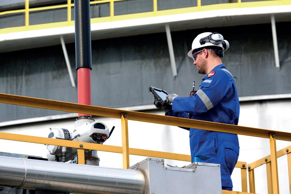
Analysing performance metrics from equipment allows for patterns to be identified that might indicate impending breakdowns. Predictive maintenance enables the early detection of anomalies or signs of wear, allowing for timely interventions before a critical failure occurs. By catching potential issues early, costly downtime and repairs can be avoided, ensuring continued smooth operation and optimal equipment lifespan.
Unplanned downtime caused by equipment failure or non-performing equipment has multiple damaging consequences, such as poor performance, poor product quality and reduced output yields, which can lead to reputational damage and loss of revenue.
An effective maintenance programme ensures that hardworking flow control assets operate at optimum performance levels, maintaining their availability to perform key duties and assist a site in working safely, efficiently and reliably. It can also provide insight into how equipment is performing, which is an important consideration for a site to work safely and efficiently.
Modern intelligent actuator technology can provide plant managers with a considerable amount of data, recording all the activity in detail, including the number of valve operations, alarms, failures to respond to events, valve torque profiles, unauthorised operation attempts and many other events. This data can be used for the accurate reporting and monitoring of the condition of actuators and flow control equipment. This information is used within asset management programmes to understand the health of actuators and valves as well as their ability to operate. Intelligent actuators facilitate the monitoring of the overall health of the process through data logs.
Using this data to manage technical and maintenance support increases plant availability and helps to avoid costly, unplanned downtime. The ongoing technical and maintenance support that an asset management system provides further contributes to increases in availability and reliability, leading to improvements in operational performance. Investment in an asset management strategy that looks at the maintenance and operability of actuated valves increases the productive life of the equipment. It moves beyond a ‘break and fix’ strategy to one that actively monitors the health of all equipment in the field, enabling action where necessary before costly and unnecessary breakdowns. The customer does not need to manually review data, saving time and reducing the likelihood of missing any problems. The early detection of anomalies allows for timely maintenance, which can reduce process downtime.
Intelligent asset management keeps sites flowing
Prevention through sound asset management and maintenance is the key to site uptime. One of the ways to do this is through analytical insights from data. Regular, accurate information about site equipment will allow for lower maintenance costs in the long-term and grants a better idea of how the operation is performing holistically. Intelligent asset management is a key component of
46 Summer 2024
Figure 1. Having the right support for your operation can significantly reduce downtime.
operations, and it allows an organisation’s coordinated activity to realise its equipment’s true value.
A system such as Rotork’s Intelligent Asset Management (iAM), which is cloud-based, can collect information from the data within the intelligent actuators. It is a reliable, secure, easy-to-use web platform that works with all operating systems and has a user-friendly, intuitive layout. Colour-coded maps and summary displays condense complicated statistics into simple images. The user may quickly and easily view a complete picture of the condition of the valves and related flow control equipment.
When predictive maintenance is combined with preventative maintenance, it offers operators a fixed cost, simplifying budget management. They also provide plans focusing on long-term maintenance and support rather than merely dispatching an engineer to repair a damaged or failing actuator. This strategy helps manage the long-term sustainability of a whole facility and boosts uptime while reducing unexpected repair expenses.
Improving site uptime
One specific example of this can be found where a service programme helped improve a site’s uptime and optimised its processes at a major petroleum terminal in Malaysia. The project involved the construction and maintenance of storage and distribution facilities needed to transport crude oil, petroleum, chemical and petrochemical products to the Refinery & Petrochemicals Integrated Development (RAPID) tank farm. The end user ordered
more than 570 intelligent IQ3 multi-turn actuators, which were ideal due to their operational accuracy, the ability to download the data logs, and power supply options. IQ3 actuators are also ATEX-certified and suitable for Safety Integrity Level 2/3 applications. Rotork site services carried out extensive on-site commissioning. They provided field support for repairs, upgrades and maintenance through a global network of fully trained and experienced service engineers. This onsite support helped to reduce downtime and improve operational efficiency.
Conclusion
An efficient and functional site service programme is essential and cannot be underestimated. Beyond financial and efficiency considerations, maintaining smooth operations at a site is crucial. The maintenance of site equipment through intelligent actuation is a robust and proven solution to potential unplanned downtime.
Understanding what a customer needs is essential; once understood, it is possible to create a plan to keep equipment continuously available to reduce downtime and improve performance. Asset management programmes should include bespoke spares programmes, site surveys, and maintenance options.
Combining customisable preventative maintenance with a predictive programme, like an intelligent asset management system, can reduce the chance of failure to near zero, reducing downtime, increasing profitability and improving a site’s overall safety.



Need a reprint? +44 (0)1252 718999 reprints@tanksterminals.com We can tailor to your requirements, produce 1 - 12 page formats, print colour or mono and more
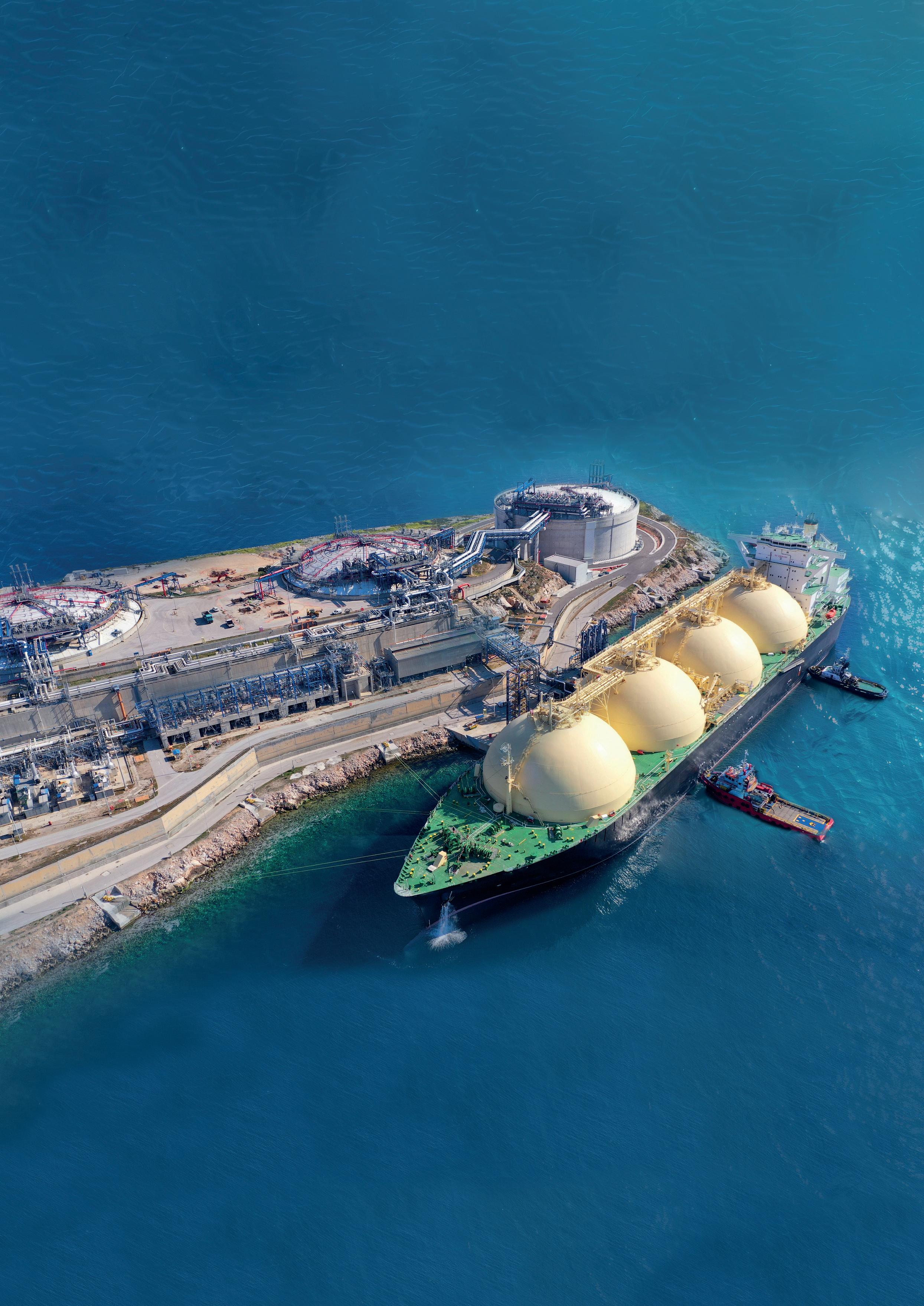
Sébastien Vermeulen, Trillium Flow Technologies, France, explains how valves have been designed to address the unique challenges of the LNG market.
In the search for efficient alternative energy sources to reduce greenhouse gas (GHG) emissions and combat global warming, countries worldwide are turning to natural gas, a cleaner-burning fossil fuel that represents an ally for the energy transition. As a result, the demand for natural gas is increasing, along with the need for safe and cost-effective methods to transport and store it.
Summer 2024 49
A recent study by McKinsey & Co., a global strategy consulting firm, predicted that world demand for gas will increase by 0.9% per year from 2018 to 2035. 1 The study further revealed that the demand for LNG was projected to grow by 3.6% annually during the same period. This is primarily because LNG is considered the best method for transporting and storing natural gas.
Safety and security are of the utmost importance in the development of LNG. To ensure this, the industry operates under a highly regulated framework that is governed by a variety of codes and standards defined by international, national, and regional organisations, governmental bodies, and standardisation agencies. These regulations aim to ensure the safety, quality, and efficiency of LNG facilities and operations across the entire supply chain. Their ongoing evolution and update are essential in adapting to changes in the energy and technological landscape, and driving sustainable and safe development in the LNG sector.
LNG projects are highly complex, placing unique demands on equipment and systems for safe operation at critically low temperatures. A range of valve solutions are available to assist LNG operators with the unique challenges facing their projects.
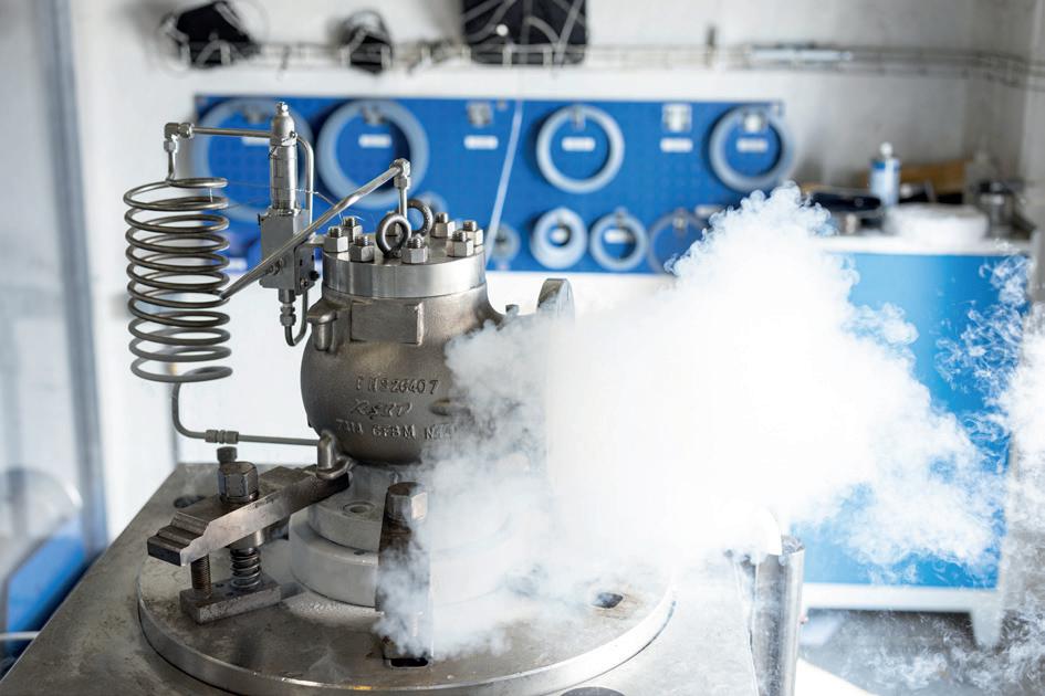
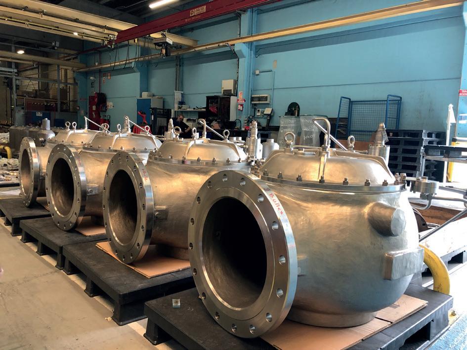
What is LNG?
Natural gas liquids (NGLs) are a group of hydrocarbons that include ethane, propane, normal butane, isobutane, and pentanes plus. They are byproducts of natural gas processing and refining.
LNG, on the other hand, only refers to methane, which is the remaining natural gas after most of the NGLs have been removed. It is cooled to the point of liquefaction (-258°F/-161°C) to reduce its volume by about 600 times, thus facilitating storage and transportation.
For every stage of the natural gas stream process, from gas receiving to liquefaction, storage, transportation, and regasification, valve trims must be carefully selected based on process conditions. For specific wetted parts, material selection is based on whether the valve is for a sour gas service or an acid gas removal system.
Methane’s main challenge
One of the main concerns for LNG operators is reducing methane emissions. Methane has a much shorter atmospheric lifetime than carbon dioxide (CO 2 ) around 12 years compared with centuries for CO 2 but it is a much more potent GHG, absorbing significantly more energy while it exists in the atmosphere. Methane has more than 80 times the warming power of CO 2 over the first 20 years after it reaches the atmosphere.
Methane emissions can be caused by various factors, including leaks (fugitive emissions) and routine venting during natural gas production, processing, and transportation. In addition, venting from storage tanks, dehydrators, and depressurising equipment before maintenance can also produce emissions. The magnitude of vented emissions per venting event is estimated at 2.6% (by mass) of the initial amount of liquid in the tank. 2
Methane fugitive emissions reduction
Fugitive emissions can come from all types of process equipment, but a common source of such emissions is through leakage from valve packing glands. This applies to any type of valve in the system that uses a packed gland to eliminate stem leakage. A range of solutions are available to reduce both routine and non-routine methane emissions. Customised isolation (gate, globe, check and ball) and control valve solutions can help operators achieve their fugitive emission reduction goals. Trillium Flow Technologies’ isolation and control valves are designed to comply with ISO 15848-1, which specifies testing procedures for the evaluation of external leakage of valve stem seals and body joints of isolating and control valves intended for use in volatile air pollutants and hazardous fluids.
For tank storage, pilot-operated low-pressure relief valves are designed for improved tightness, thereby retaining more product in the tank.
Figure 1. LNG pilot-operated relief valve testing at Trillium's facility in France.
50 Summer 2024
Figure 2. LNG pilot-operated relief valves at Trillium's facility in France.
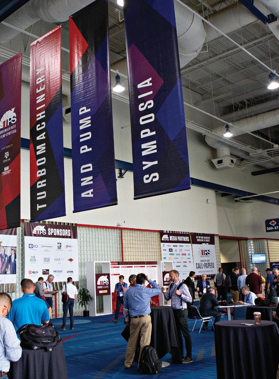

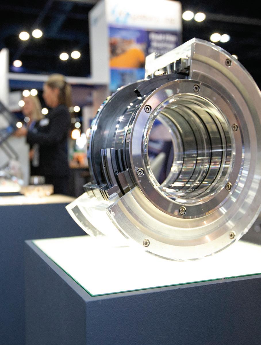














SHORT COURSES: AUGUST 19, 2024
SYMPOSIA: AUGUST 20-22, 2024
GEORGE R. BROWN CONVENTION CENTER • HOUSTON, TX
The Turbomachinery & Pump Symposia is recognized worldwide as the industry’s must-attend event. Connect with more than 4,900 delegates, meet with leading suppliers, observe product demos, and get answers to your technical questions. We look forward to seeing you in Houston!
4,945 ATTENDEES
323 EXHIBITING COMPANIES
53 COUNTRIES
TPS.TAMU.EDU #TPS2024
HOSTED BY
BRINGING
AND
TOGETHER.
EDUCATION
INDUSTRY
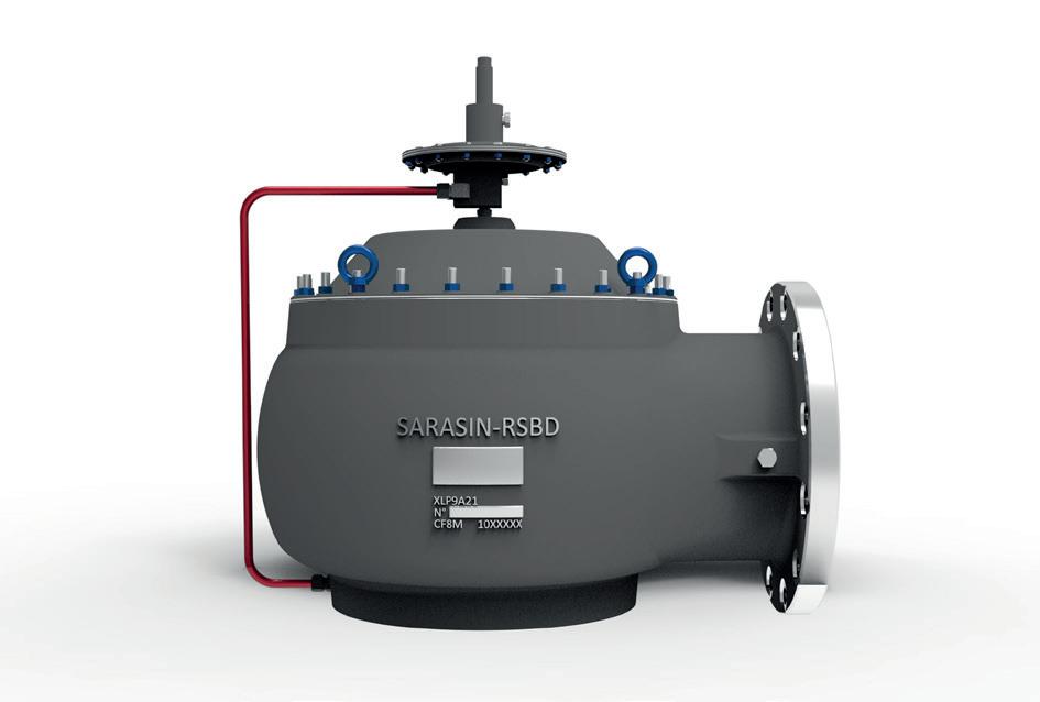
3. Sarasin-RSBD® 74 Series pilot-operated pressure relief valve for LNG services.
Trillium’s Sarasin-RSBD® 74 Valve Series represents a highly accurate and easy-to-set safety device that offers efficient storage and reduces operation risk. Compared to a standard weight-loaded vent with simple construction, this product offering is more stable near the set pressure, acting according to a simple rule: the higher the pressure, the better the bubble tight level. The modulating flowing action pilot adjusts the main valve lift, thus limiting the valve’s relieving time. Relieving capacity is achieved at a maximum of 10% overpressure, decreasing the pressure and optimising the tank holding time.
Manufacturing and testing quality
Manufacturing quality is imperative for the LNG market. Critical components undergo strict inspection, and sensitive areas such as the machined functional surfaces of castings (hard-faced or lapped parts) are subject to a Liquid Penetrant Examination performed by qualified technicians (Cofrend Level II or SNT-TC-1A, in Trillium’s case). This process involves applying a thin liquid over the entire surface and removing it with a chalk-like developer to reveal any defects. After drying, the surface is examined under a light of 1076 lx, and cracks as narrow as 150 μ m are detected where the liquid has remained trapped.
The LNG’s purification process also requires the use of clean equipment, starting with the valve’s material, which is stainless steel to avoid rust. However, cleanliness is not only limited to the material of the valves but also extends to the entire assembly process. Manufacturers follow strict procedures to ensure all possible contaminants are tightly controlled. At Trillium, for example, pressure relief valves for LNG are assembled in a dedicated white room, following specific protocols to prevent cross-contamination. Parts are degreased and treated with approved lubricants before assembly. The air used for testing is also oil-free. Moreover, the skilled technicians who access the white room wear sanitised equipment, such as lint-free white overalls, Charlotte fleece, and overboots.
A manufacturer’s testing capabilities are also crucial to meet the requirements of the LNG market.
Trillium has in-house testing facilities where fugitive emission testing is performed according to the ISO 15848-1 standard to ensure the assembled pressure-containing parts and seat are perfectly tight. The leak tightness is measured using pure helium at more than 99%, and the acceptance criteria, based on calibrated mass spectrometer analysis, is stringent at less than 10 – 8 Pa.m³/s.
As LNG is cooled to the point of liquefaction, cryogenic testing must also be performed to guarantee valve performance at actual operating conditions. Valves are tested as per #EN 13648-1 standard using pure nitrogen at 100%. This time, leak tightness at the outlet flange is measured as per API STD 527 (KELLOG test).
Case studies
Trillium has supplied more than 500 critical service safety valves for a major LNG plant project located in an area that is subject to subzero ambient temperatures during most of the year. This specific weather condition represented a challenging operating condition. All the engineered safety valves supplied were subject to the company’s rigorous manufacturing processes and in-house cryogenic testing. Nearly a third of the required valves were delivered within a 22-week turnaround to meet the customer’s installation and start-up schedules.
Trillium has also participated in various phases of an Asian country’s first LNG terminal and associated high-pressure pipelines project initiated in the early 2000s. The company was contracted for Phase 1 of the project to supply a large number of control valves for the LNG receiving terminal and regasification plant. Trillium supplied a range of valves including large diametre control butterfly valves to control the flow of seawater in the project’s LNG vaporisers, which are used to regasify the LNG; cryogenic globe valves for LNG; and high-pressure gas let-down valves. Trillium was awarded further contracts for later phases of the same project and similar LNG plants in the country, supplying cryogenically tested control valves for LNG up to 16 in. in size.
Conclusion
The LNG market is a challenging industry that demands safe and reliable equipment and systems to operate at extremely low temperatures. Innovative customer-centric valve suppliers can support industry operators to meet their ever-evolving safety and sustainability objectives.
References
1. 'Global Natural Gas & LNG Outlook to 2035', McKinsey & Co., (September 2018), https://www. mckinsey.com/solutions/energy-insights/global-gas-lngoutlook-to-2035/~/media/3C7FB7DF5E4A47E393AF0CDB0 80FAD08.ashx
2. URSAN, M., 'What is boil-off?' paper prepared for the LNG task force meeting, Brussels, Belgium, (3 November 2011), retrieved from: http://www.unece.org/fileadmin/DAM/trans/ doc/2011/wp29grpe/LNG_TF-02-06e.pdf
52 Summer 2024
Figure

Thomas Hartmann, DNV, Norway, discusses the updated Shore Power class notation, which addresses the safety requirements for tankers lying at berth.
Ports and coastal states around the world have passed – or are preparing – legislation to curb air pollution from ships lying at berth, and to help cut carbon emissions in general.
Summer 2024 53
Using shore power is a great way for ships to keep their on-board systems running without emitting smoke and CO 2 . As the first rule set of its kind, DNV’s updated Shore Power class notation, effective as of 1 July 2023, addresses the specific safety needs of tankers.
International regulations and standards
Legislative advancements have prompted tanker owners to inquire about rules and standards for shore power for their ship type. The latest version of the California Air Resources Board’s (CARB) Ocean-Going Vessels At-Berth Regulation, published on 1 July 2023, requires tankers to have emission control strategies in place at specific Californian ports from January 2025. The EU has adopted similar legislation for container and passenger vessels, the ship types with the highest non-propulsion power demand, as part of the
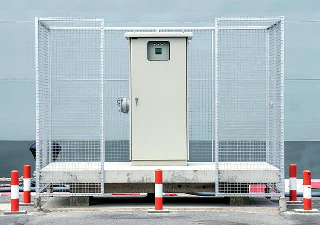
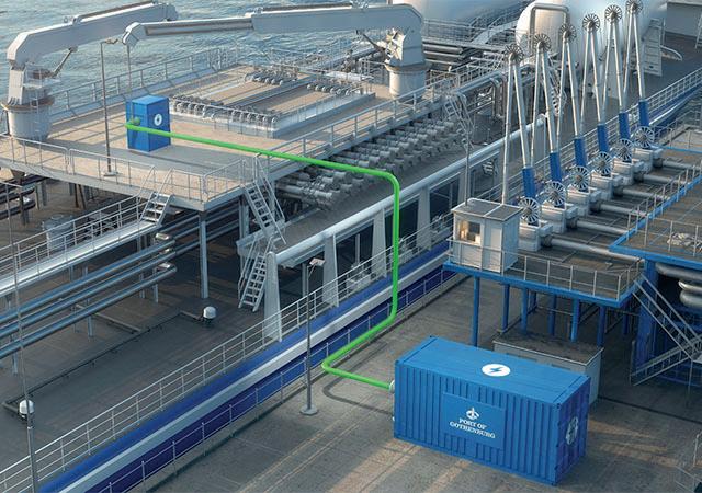
Fit for 55 package, including requirements for onshore power supply.
Hazardous cargo
While the EU regulations do not apply to tankers, the unrivalled simplicity of plugging in a cable makes ‘cold ironing’ (the process of providing a ship with shoreside electrical power while its auxiliary engines are switched off) an attractive option to meet emission control requirements during port stays of nearly any ship type. What has made the development of appropriate rules for tankers difficult is the volatile nature of the type of cargo they carry. With tankers that often carry potentially flammable cargoes, the electrical risks can be greater than for dry bulk carriers and containerships. This requires more attention to system safety both on board and on the quayside.
IEC standards
The crucial question is how and where to arrange the connecting points and cables safely. Class rules are often based on the relevant international standards. The relevant IEC standard calls for installation and testing of shore power equipment on board to be witnessed by an ‘appropriate authority’, which is typically the classification society that reviews the engineering designs for newbuilding and retrofitting projects. Ensuring a safe working environment for people on board tankers is a complex task.
Complexities of shore power connection
Since ship types differ in terms of power demand, space restrictions, and safety areas on board, they are addressed separately by both the IEC standard and the DNV Shore Power class notation. Class rules must ensure safety without hampering ‘novel designs’ – the creative ideas the industry depends on to find new and better ways to build ships. In theory, the best and safest location for a shore power connection on board a tanker would be the aft section. But that is a challenge because of the way oil terminal jetties are normally designed. This is why DNV defined its rules allowing safe shore power connections midship – in the hazardous area of a tanker where the cargo manifolds are located.
Working with the industry
In response to the CARB regulatory changes, DNV, on behalf of the Western States Petroleum Association, performed a comprehensive gap analysis and identified a number of shortcomings in the regulatory landscape, including a lack of standardisation for connection points, limited interface compatibility with terminal systems, and technology development constraints. These gaps underscored the importance of establishing industry-standard guidelines to address safety
Figure 2. At its energy terminal, the Port of Gothenburg, Sweden, has installed a shoreside power system called Green Cable that aims to become an international standard.
54 Summer 2024
Figure 1. Onshore connection points for tankers require special protective features to avoid accidental sparking and mechanical impact, and air overpressure to displace flammable vapours.

The 2024 API Storage Tank Conference will give attendees an opportunity to learn about new and existing industry codes and standards, including industry best practices, and provide an opportunity to hear about emerging trends from industry experts. This conference offers over 25 sessions addressing the needs of individuals involved in production systems, pipelines, terminals, refining, and storage facilities. Each day focuses on presentations relevant to upstream, midstream and downstream.
Copyright 2024 – American Petroleum Institute, all rights reserved. API, and the API logo are trademarks or registered trademarks of API in the United States and/or other countries. Register at www.API.org/storagetank CONFERENCE & EXPO 2024 API
OCTOBER 7-10, 2024 | THE WESTIN FORT LAUDERDALE BEACH RESORT, FORT LAUDERDALE, FL
STORAGE TANK
concerns effectively and ensure the well-being of personnel and assets involved in tanker operations.
Collaborative efforts
A joint industry working group, the Onshore Power Supply Work Group, was formed to develop guidance for standardised practices for the application of shore power for tankers, terminals and their interfaces. Initiated by the Oil Companies International Marine Forum’s (OCIMF) Environment Committee, it included Intertanko, the standards institutes, IACS representatives and DNV. This group and other stakeholders were part of the hearing conducted by DNV in March 2023 to ensure a comprehensive and inclusive process for DNV’s new rules.
The updated DNV Shore Power class notation rules describe the requirements that a power cable connecting point must meet to ensure a safe electrical connection and prevent explosion or other hazards, along with protection for the cable in case it must be routed across deck. For example, a ‘gas-safe area’ can be created and maintained by applying forced-air ventilation, or as an alternative, by using nitrogen as a purging media, to the connecting point and installing a continuous monitoring system.
Tanker efficiency and compliance
Owners are turning every stone to reduce their fuel consumption, and ultimately, their emissions.
Shore power is therefore very interesting, especially for owners of ‘smaller’ tankers. Recent updates to international decarbonisation regulations are placing greater emphasis on shore power.
It makes sense to consider the shore power option from the newbuilding planning stages and make some preparatory arrangements for later retrofits, because retrofitting shore power equipment on tankers is usually difficult and costly. DNV is considering offering a ‘shore-power-ready’ qualifier for ships prepared for conversion at a later time. Customers can approach DNV for an informal meeting before beginning a newbuilding or conversion project to get the latest input from the industry on the development of shore power in the terminals. This can avoid unnecessary headaches at a later stage.
The evolving landscape of maritime standards and trends
Standards and class rules, propulsion and energy technologies are developing, and no-one can predict where these developments will ultimately lead. Shipbuilders and shipowners are well advised to keep an eye on market and industry trends and follow the discussion. Shore power is definitely a realistic option for complying with in-port emission restrictions and will play a major role.
AD INDEX Page Number | Advertiser 09 | American Petroleum Institute (API) 55 | API Storage Tank Conference & Expo OBC | AUMA 02 | Chart Industries 19 | E²G | The Equity Engineering Group, Inc. 35 | Elementale Enterprises Inc. OFC & 17 | Endress+Hauser 43 | GEA 13 | Kanon Loading Equipment 04 | Midwest Steel 44, 47, 48, IBC | Palladian Publications 27 | Paratherm 40 | REMBE® GmbH Safety+Control IFC | Rotork 51 | Turbomachinery & Pump Symposia 39 | United Riverhead Terminal, Inc. 31 | Zwick Armaturen GmbH 56 Summer 2024






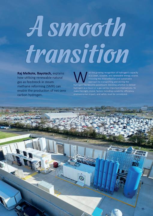

www.globalhydrogenreview.com



Global Publication
The Spring issue of GlobalHydrogenReview is out now Read the issue here Subscribe for free:

AUMA PROFOX-X Learn more about our smart actuators PROFOX-X ACTUATORS SAFETY THANKS TO CERTIFICATION profox.auma.com
