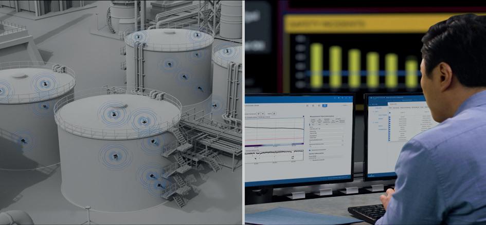
Future ready terminal operations start with digitization.
The next performance gains come from smarter digitization.
Connect operational technology and business systems to modernize step by step - improve decision-making, increase near real-time insight, reduce manual work, and enable progress even in complex brownfield environments.
Start building a smarter, more resilient terminal.
03 Guest comment
04 Barrels and bright futures
A multi-generational change, equal to the oil price shocks of the 1970s, is sweeping through the world energy market. Gordon Cope, Contributing Editor, considers the impact of such changes for the North American oil and gas storage sector.
08 Innovative storage solutions to meet growing demand
Brian Wiese, CB&I, USA, explores how innovations in liquid nitrogen (LIN) tank design are unlocking larger capacities and offering valuable lessons for the energy storage sector.
13 The next phase of terminal optimisation
Cody Falcon, ABB Energy Industries, explores how LNG terminal operators can utilise automation to ensure facilities are optimised.
17 Digitalising tank data collection
Bram Sijbers, ROSEN, discusses how digitalising tank inspection data can allow for improved predictive integrity management, to ensure the safe and efficient operation of aboveground storage tanks.
21 Monitoring tank corrosion to prevent incidents
William Fazackerley, Emerson, explains how wireless ultrasonic metal thickness detectors can provide an answer to the problem of rusting storage tanks.
25 Digitalisation in confined space entry
Ajin Prasanthan, Dräger, Germany, outlines why a connected process can contribute to higher levels of occupational safety and greater operational efficiency.
29 Managing emissions in storage terminals
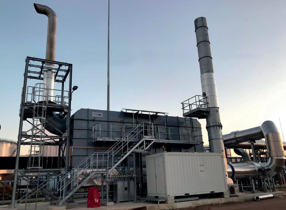
José Miguel González, Tecam, looks at practical approaches to achieving emissions compliance and operational efficiency.
33 Optimising terminal operations
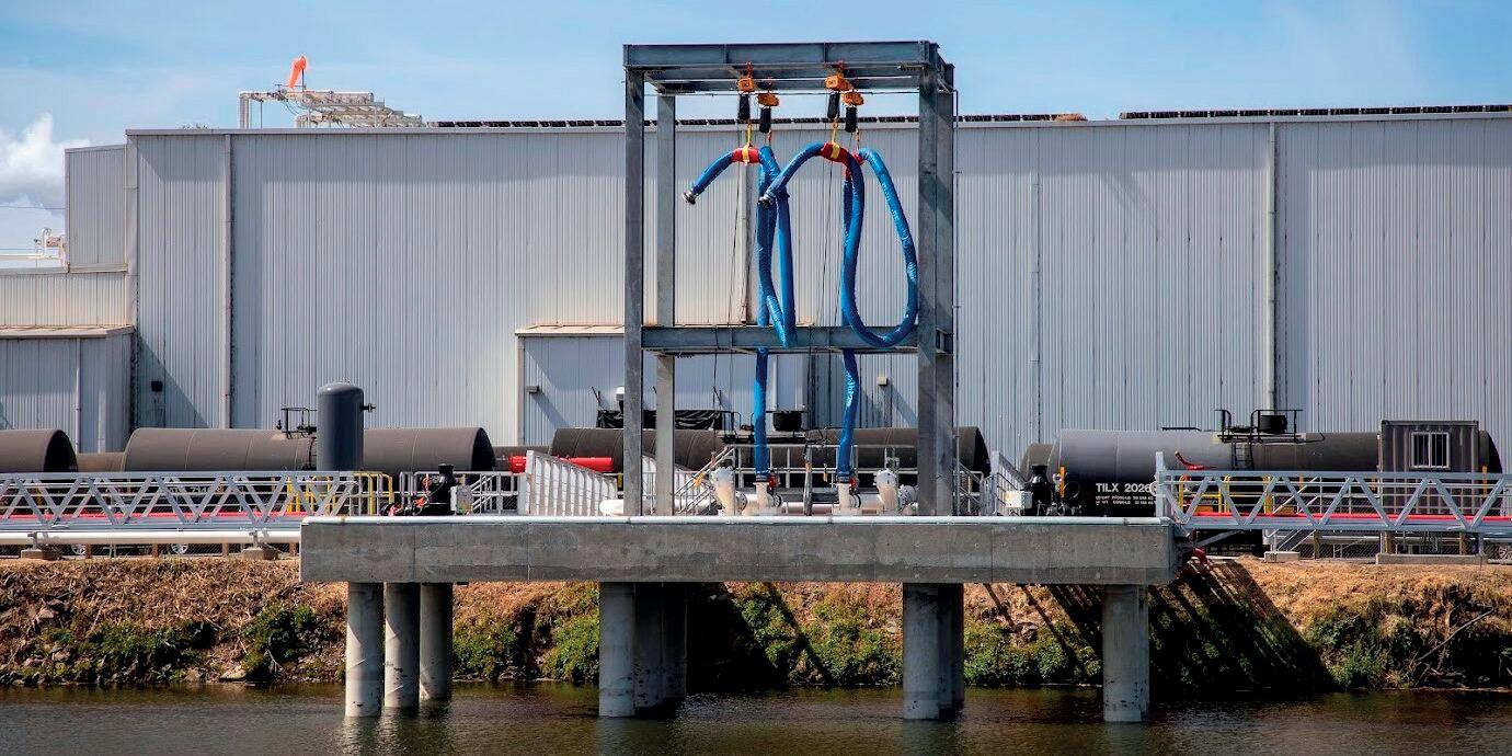
Brandon Melerine and James Hill, BWC Terminals, discuss how terminal infrastructure can be optimised to ensure smooth operations amid the increasing distribution of renewable fuels, with particular emphasis on the Port of Stockton, California, US.
37 Coatings under attack
Gard Reian, Jotun AS, considers the challenge that storing biofuel feedstocks presents for modern tank lining technologies.
41 A practical path to performance improvement
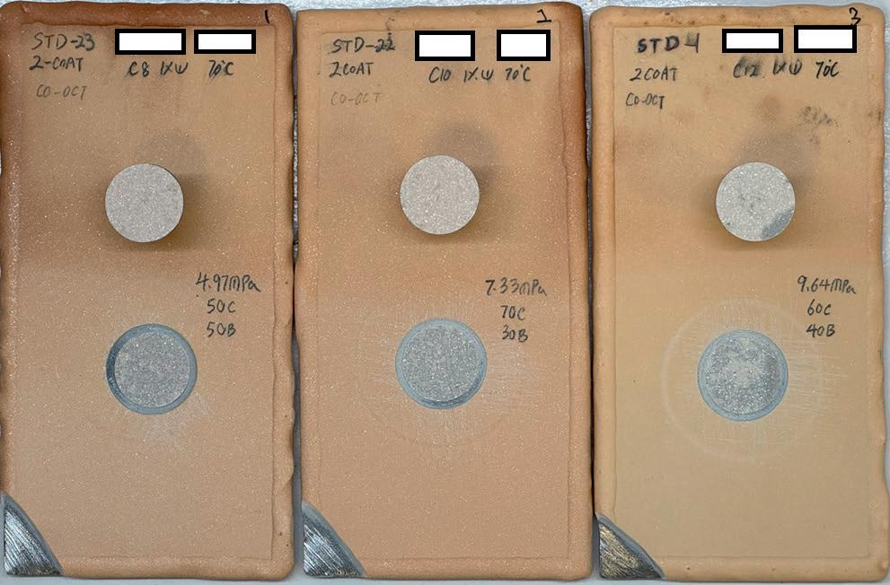
John Zimmerman, Calvin Sumner, and Rob Galvin, Sherwin-Williams Protective & Marine, consider how strategic lining overcoats can help to extend storage tank performance and achieve significant savings.
47 Forward-thinking corrosion protection
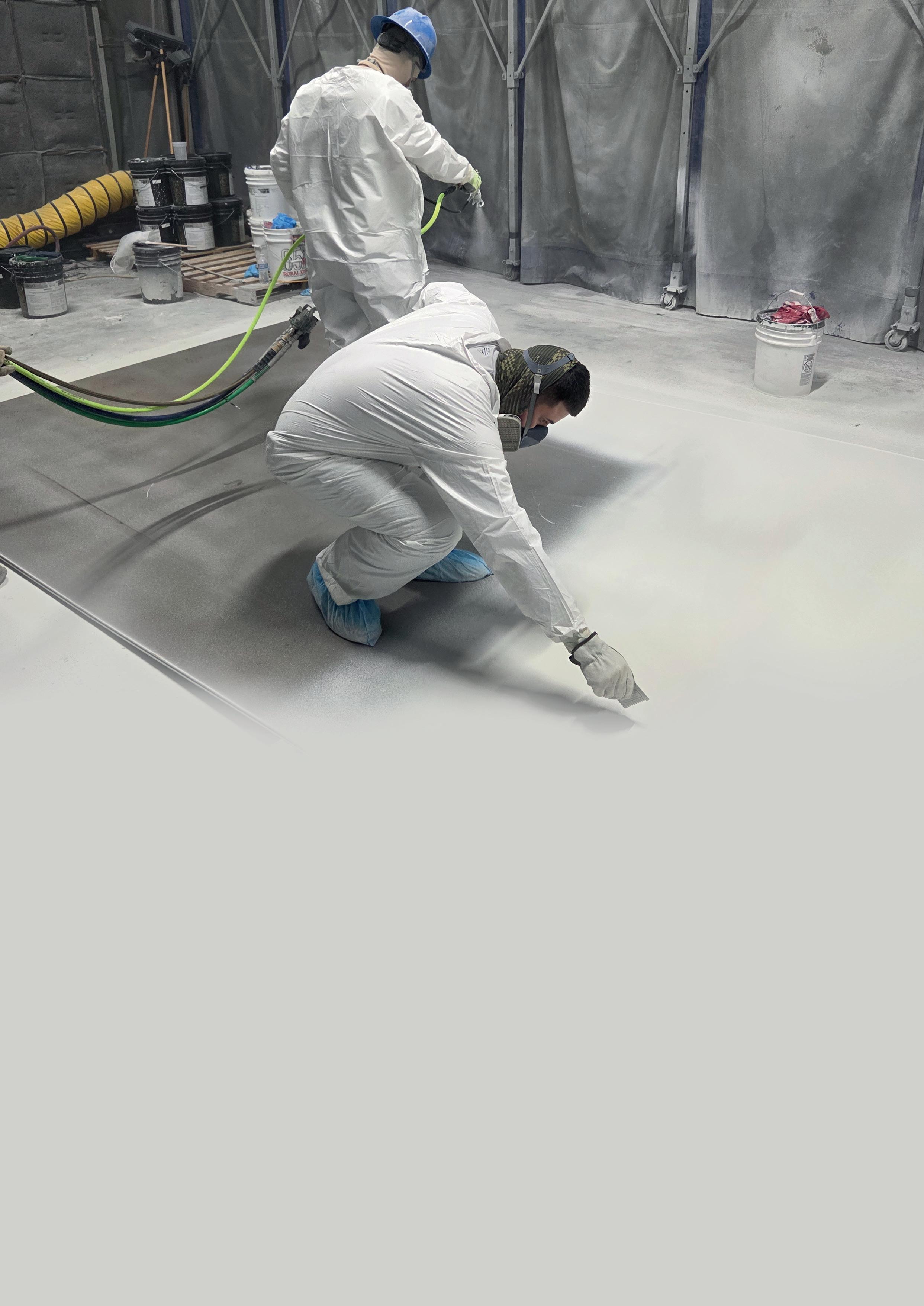
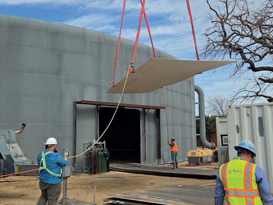
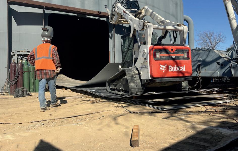
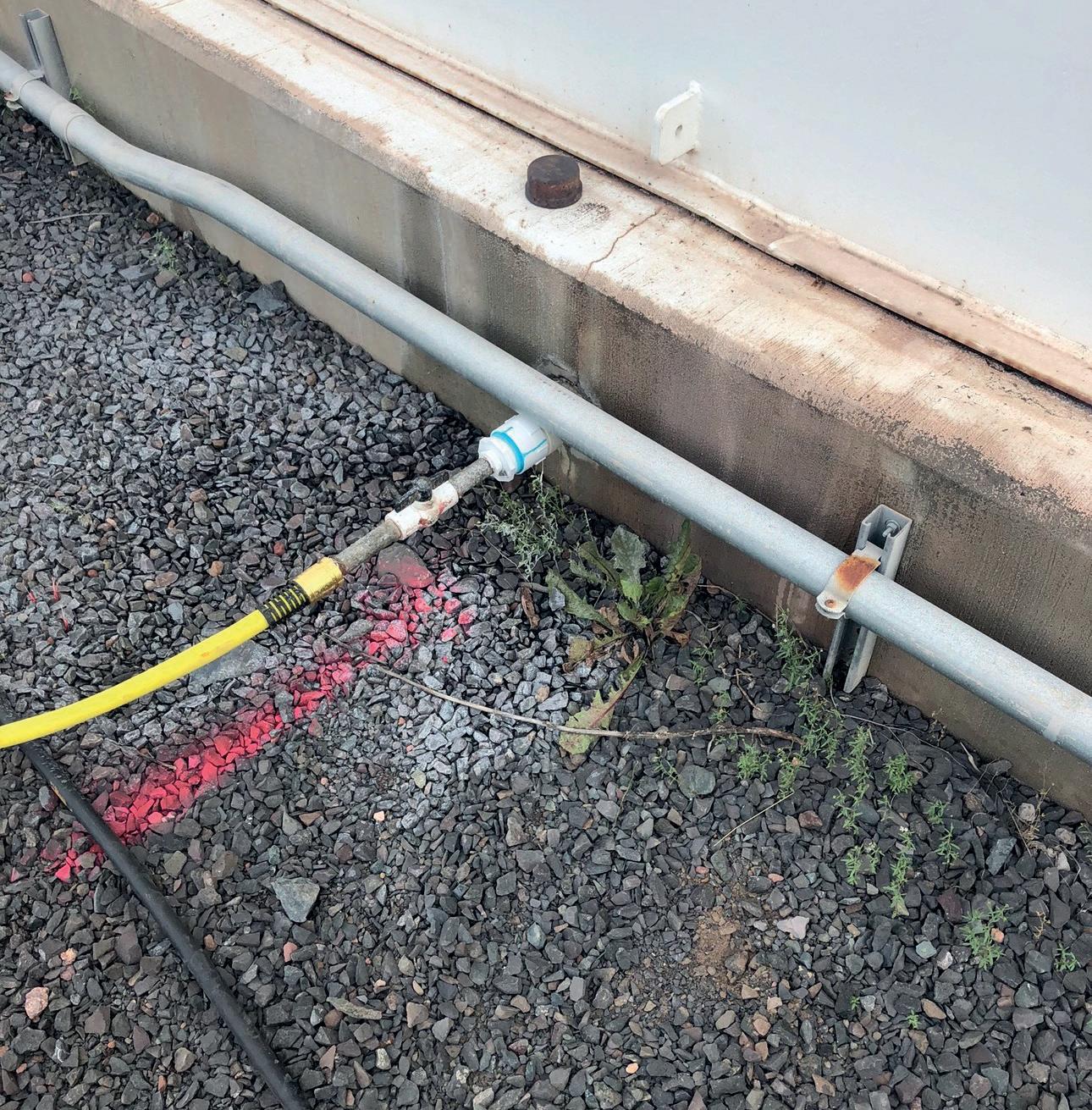
Tony Collins, Eoncoat, USA, presents a case study of a tank bottom project where corrosion protection meets environmental responsibility.
49 A shift in corrosion prevention po tential
Julie Holmquist, Cortec® Corp., and Shane Baker, Cortec Global Services (CGS), discuss the benefits of vapour corrosion inhibitor (VCI) technology for tank bottom and cased pipeline corrosion mitigation.
CB&I delivers integrated storage and asset‑management solutions that help customers operate across the lifecycle of their facilities. Through its global business units – Storage Solutions, a world leader in tanks, terminals, and storage systems, and Asset Solutions, a leading provider of operations, management, wells, and decommissioning services – CB&I combines technical excellence with execution capability to extend asset life, optimise performance, and maximise value. To learn more, visit www.cbi.com.
GUEST COM MENT
CONTACT INFO
MANAGING EDITOR James Little james.little@palladianpublications.com
DIGITAL CONTENT COORDINATOR Kristian Ilasko kristian.ilasko@palladianpublications.com
DIGITAL ADMINISTRATOR Nicole Harman Smith nicole.harman-smith@palladianpublications.com
VIDEO & MOTION GRAPHICS Amélie Meury Cashman amelie.meury-cashman@palladianpublications.com
ADMIN MANAGER Laura White laura.white@palladianpublications.com
CONTRIBUTING EDITORS
Nancy Yamaguchi Gordon Cope
SUBSCRIPTION RATES
Annual subscription £110 UK including postage /£125 overseas (postage airmail).
Two year discounted rate £176 UK including postage/£200 overseas (postage airmail).
SUBSCRIPTION CLAIMS
Claims for non receipt of issues must be made within 3 months of publication of the issue or they will not be honoured without charge.
APPLICABLE ONLY TO USA & CANADA
Tanks & Terminals is a supplement of Hydrocarbon Engineering. Hydrocarbon Engineering (ISSN No: 1468-9340, USPS No: 020-998) is published monthly by Palladian Publications Ltd GBR and distributed in the USA by Asendia USA, 701C Ashland Avenue, Folcroft, PA 19032. Periodicals postage paid at Philadelphia, PA & additional mailing offices.
POSTMASTER: send address changes to HYDROCARBON ENGINEERING, 701C Ashland Ave, Folcroft PA 19032.
T15 South Street, Farnham, Surrey GU9 7QU, UK
LOREN EISENLOHR VICE PRESIDENT OF BRAND STRATEGY AND MEMBER ENGAGEMENT, INTERNATIONAL LIQUID TERMINALS ASSOCIATION (ILTA)
he liquid terminal sector is operating in an increasingly interconnected environment, where multiple priorities are advancing at once and decisions carry broader implications across the organisation. Environmental expectations, system reliability, workforce development, and security considerations are now closely linked. For terminal operators, the challenge is not simply identifying these pressures, but determining how to respond and implement in a way that is effective under real operating conditions.
The ILTA 2026 Conference & Trade Show, taking place 15 - 17 June in Houston, Texas, US, is positioned directly within that context. As the largest event dedicated exclusively to the business and technology of liquid terminals, it brings together more than 4500 professionals who are actively navigating shared challenges. The value of the event lies both in surfacing important developments across the sector and in advancing how those developments are applied in practice.
One of the most immediate areas of focus remains the transition away from aqueous film forming foam (AFFF) and the broader implications of per and polyfluoroalkyl substances (PFAS). What was once a standardised approach to fire suppression is now a complex operational decision, shaped by environmental responsibility, system compatibility, and long-term risk considerations. Operators are weighing performance expectations against infrastructure limitations, while also addressing legacy materials and evolving guidance. The shift to fluorine-free alternatives is not uniform, and the path forward continues to require careful evaluation and practical tradeoffs.
Security considerations are also expanding in scope. The convergence of operational technology and information systems has elevated cybersecurity as a core operational concern, while the increasing presence of drones introduces new challenges around facility visibility and control. These dynamics are reshaping how operators think about infrastructure protection, requiring closer coordination across functions and a more integrated approach to risk.
At the same time, workforce-related factors are taking on greater operational significance. High-hazard environments have long relied on procedures and systems, but there is growing recognition that performance is equally influenced by leadership behaviour, organisational pressure, and the conditions under which decisions are made. Concepts such as fatigue risk management and psychological safety are being evaluated not as abstract ideas, but as practical mechanisms that support early risk detection, stronger communication, and more consistent execution.
The ILTA 2026 Conference programme reflects this shift, with sessions focused on how these challenges are being addressed in real operations. Topics include PFAS transition strategies and infrastructure considerations, evolving security risks, and the role of leadership and workforce dynamics in process safety. The programme is built around what operators are actively managing today.
ILTA’s designation as an IACET Accredited Provider adds a meaningful dimension to the experience, with 21 CEU-eligible sessions supporting ongoing professional development and helping attendees meet certification and credentialing requirements across a range of disciplines.
For terminal operators, time away from the facility must deliver value. ILTA 2026 offers direct access to peer insight, practical approaches, and solutions that can inform decision-making and strengthen performance. In an environment that increasingly depends on coordination across a multidisciplinary workforce, that kind of perspective is critical.
A
multi-generational change, equal to the oil price shocks of
the 1970s,
is sweeping through the world energy market. Gordon Cope, Contributing Editor, considers the impact of such changes for the North American oil and gas storage sector.
The effects of regional conflicts in the Middle East began to spiral into international energy markets in March 2026, when Israel and the US launched an attack on Iran. In response, Iran blockaded the Strait of Hormuz, effectively removing 20 million bpd of water-born crude and 300 000 m3/d of LNG shipments. It also began to attack energy assets in the Middle East, including terminals and storage facilities. Prices spiked overnight, briefly doubling the cost of crude.
While consuming nations scramble to deal with short-term shortfalls, it is abundantly clear that Canada and the US, both energy exporters, will undertake major shifts that will have long-term repercussions for North America’s energy sector, including tanks and terminals. This article will examine some of the major transformations.
Crude exports to Asia will increase
The oil sands of Alberta are some of the largest crude reserves on earth, holding an estimated 160 billion bbl of recoverable bitumen. As of 2025, 3.5 million bpd were being produced from open pit mines and steam assisted gravity drainage (SAGD). Alberta’s Premier Danielle Smith has predicted that production could grow to 8 million bpd by 2035. Asian consumers are keenly interested.
That makes a clear business case for Canada to increase Pacific tidewater capacity. In May 2024, the Trans Mountain Expansion (TMX) was officially launched. The much-delayed expansion added 590 000 bpd to an existing 300 000 bpd line that runs from Alberta to the Westridge Marine Terminal in Burnaby, British Columbia, near Vancouver. Trans Mountain had already expanded the port; it now has 15 million bbl of crude storage and three berths that can handle up to 34 Aframax ships per month. Further additions are likely in the offing; the operator has applied to add drag reducing agents (DRAs) to reduce friction on pipe walls, allowing for an increase in capacity of 90 000 bpd, and, in the longer term, to add pumping stations to boost capacity by a further 200 000 bpd. In light of recent events, the company is urging regulators to speed up approvals.
Prime Minister Mark Carney has made export projects a priority, and, alongside Alberta Premier Smith, has agreed to promote a new west coast pipeline similar in size to the TMX. While implementation faces regulatory obstacles, First Nations opposition, and shipping bans, a new export terminal on the British Columbia coast would require piers and tanks equalling Westridge’s capacity.
Due to the burgeoning Montney shale play in northeast British Columbia that produces LPG as a side-product, exports of LPG from Canada to Asia have surged. Since 2021, Alta Gas and Pembina Pipeline have been exporting over 170 000 bpd of propane to Japan, Korea, and China from the port of Prince Rupert, British Columbia. As both supply from the Montney shale gas play and demand in Asia for new (non-tariff) sources grow, Alta Gas and other companies are building a further 160 000 bpd of capacity with an additional 60 000 bpd on the drawing boards. If all goes according to plan, the port would have around 400 000 bpd capacity by the end of the decade.
The US has expanded its crude output tremendously over the last 15 years, primarily through the development of shale reserves. Production now stands at 13.8 million bpd; with the Permian Basin alone accounting for over 6.6 million bpd. Because the US has a secure supply from Canada, it is unlikely to re-apply an export ban like it did in the 1970s. Rather, attention will focus on its massive export facilities in the Gulf Coast.
US Gulf Coast (USGC) export terminals, including the Energy Transfer’s Nederland Terminal, the Houston Fuel Oil Terminal, and Louisiana Offshore Oil Port (LOOP), have a nameplate export capacity of 4.4 million bpd and storage capacity of almost 100 million bbl. Their growth over the last decade has been spurred by the development of the Permian Basin. When the US Energy Information Administration (EIA) reported that basin output had peaked, however, it cooled the impetus to build deep-water export ports in the Gulf to allow supertankers to fill directly. Currently, LOOP is the only facility that can fully load a 2 million bbl very large crude carrier (VLCC). The Enbridge Ingleside Energy Centre (EIEC) and the South Texas Gateway Terminal (STGT), both in Corpus Christi, Texas, require lightering to reach full loads.
The development of Enterprise Products Partners’ offshore Sea Port Oil Terminal (SPOT), Phillips 66’s Bluewater Texas project, and Energy Transfer’s Blue Marlin project are all in various stages due to regulatory issues and market conditions. The ‘Hormuz effect’ that has driven up oil prices and uncertainty of delivery now creates a strong commercial rationale for their development, especially for SPOT, which has full regulatory approval since 2024 but has languished due to low customer commitment. Starting in March 2026, Asian demand for USGC crude has skyrocketed.
LNG will continue to grow
Canada’s LNG sector is finally off the ground. LNG Canada, Shell’s 14 million tpy complex in the Pacific port of Kitimat, British Columbia, began delivering LNG to Asian customers in 2025. Nearby Cedar LNG, which will use a floating liquefaction plant to produce 4 million tpy, is scheduled to enter service in 2028. The British Columbian government is promoting the fast-track development of the 12 million tpy Ksi Lisims LNG, the 3 million tpy FortisBC plant, and the 2.1 million tpy Woodfibre LNG project. Feedstock for the plants will come from the massive unconventional gas reserves in northern British Columbia and Alberta. Several billion dollars of new tanks and terminals will be necessary to handle the load.
The Atlantic coast of Canada also has significant potential for LNG export terminals. In February 2026, an LNG cargo travelled over 25 000 km from Australia to deliver its load to a terminal in St. John, New Brunswick. The irony of having to import gas into a country that has some of the largest reserves in the world was not lost. For decades, the Canadian oil patch has been striving to deliver domestic crude and natural gas to eastern provinces, with limited success. Various provincial legislatures have thwarted pipelines due to environmental reasons, and have scuttled attempts to develop in-province resources (New Brunswick sits on approximately 80 trillion ft3 of shale gas, but prohibits fracking). Prime Minister Mark Carney is now pursuing trade alliances with Europe; east coast LNG projects, including the cancelled CAN$8.9 billion Saguenay LNG project in Quebec, are being examined in the glare of energy security. The 10 million tpy Saguenay project called for three 160 000 m3 storage tanks and two piers capable of handling over 150 shipments per year.
One year ago, the rush to build new LNG plants in the US was beginning to slow. In 2025, the EIA reported a record 13.8 billion ft3/d of exports as the Plaquemines LNG and Corpus Christi LNG Stage 3 projects came on-stream, but,
in spite of the increase in European demand spurred by Russia’s invasion of Ukraine, enthusiasm for new LNG projects was beginning to wane as costs for materials and labour rose to US$1200/t of nameplate capacity, eating into the bottom line.
Now, it is full-speed ahead. The closure of the Strait of Hormuz brought the world’s reliance on Qatari LNG into stark focus. The country essentially ceased production when Iran attacked shipping in the narrow passage as well as its main production hub at Ras Laffan Industrial City, causing prices to spike and countries to suspend industrial consumption.
Currently, there are half a dozen major LNG projects (both new-build and expansions) under construction, including Golden Pass, Rio Grande LNG, and Port Arthur LNG, representing over 80 million tpy capacity at a cost of nearly US$90 billion. Another four major projects representing a further 75 million tpy – Coastal Bend LNG, Lake Charles LNG, NextDecade Rio Grande Phase 2 & 3, Port Arthur Phase 2 – are pre final investment decision (FID).
Although FIDs are subject to a complex mix of market demand, soaring budgets, and regulatory challenges, the significant spike in security concerns regarding Middle East sources is bound to influence USGC demand as Asian consumers seek less volatile sources, and the billions of dollars in windfall profits being reaped by LNG producers on the spot market makes internal financing of new projects far more viable.
More focus on storage
The world has about 1.2 billion bbl of crude stockpiled in strategic petroleum reserves (SPRs). Tapping 20 million bpd, the approximate amount being disrupted by the blockade, would last for several months. Although the immediate international response to the Strait of Hormuz closure was to release up to 400 million bbl, jurisdictions are reluctant to commit every last barrel, as one of the prime reasons to create the SPRs in the first place was to ensure armed forces had fuel for their navies and air forces. The US operates SPRs in the USGC, with 400 million bbl stored primarily in salt domes in Texas and Louisiana. The country’s armed forces are currently burning through vast sums of diesel and jet fuel, so any drawdown must be carefully calculated.
Approximately 60 million bbl is being held by midstream assets in North America, however. The 90 000 miles of pipeline that deliver crude throughout the continent hold roughly 20 million bbl of ‘line fill.’ Canada’s largest terminal is in Hardisty, Alberta, which has a nameplate capacity of 21 million bbl. Enbridge is the biggest operator, with 10 million bbl of surface storage and 3 million in underground caverns. The company is planning to spend US$2 billion to expand its pipeline and storage capacity on the Canadian segment of its mainline system over the next two years.
The crude terminal in Cushing, Oklahoma, is the largest storage facility in the US. Eight companies, including Enbridge, Plains All American, Magellan, and Energy Transfer, own the majority of its nameplate capacity of 98 million bbl. Over the last several years, strong export demand and new pipelines to refineries has shifted Cushing’s role from a storage facility to a transit point. For over a year, storage levels have stood at around 26 million bbl, slightly above its functional limit of 22 million bbl. As such, no new tank capacity is being planned.
Challenges
North American crude and natural gas production each account for roughly one-third of world output. Major assets in Canada and the US, such as the oil sands and the Permian Basin, do not have spare capacity however, and cannot increase production overnight to compensate for the cessation of Middle East production. While higher oil prices based on demand generally motivate producers to invest in new, long-term production, price spikes caused by political unrest do not. Basing investment decisions on the current situation is exasperated by the fact that it is difficult to predict what President Trump will do next. The sudden loss of Middle Eastern output will most likely be met with demand destruction, leading to economic hardship in many countries.
Green energy also faces headwinds. When President Trump largely gutted the trillion dollars’ worth of incentives in President Biden’s Inflation Reduction Act, several industrial scale green projects were put on hold. In late 2025, ExxonMobil suspended a plan to produce low-carbon hydrogen at its refining and petrochemical facility at Baytown, Texas. The project called for up to 1 billion ft3/d of blue hydrogen, with over 98% of the associated CO2 will be captured and permanently stored underground. The site would have been the largest low-carbon hydrogen project in the world at planned start-up in 2027 - 2028.
The cost of solar power has decreased dramatically, however, and renewable proponents can make a business
case without subsidies. While solar is intermittent, it is still a viable, large scale alternative to fossil fuel utility plants.
The future
In the near-term, prices will rise, causing inflation in virtually every sector of the economy that relies on energy. Low income families will face energy poverty, in which they will have to choose between eating and heating their homes. Countries will also face demand-destruction in industries that are heavily-reliant on fossil fuel energy, including fertilizers, steel, and chemicals. Environmental concerns about global warming will take a back seat to security issues. Mothballed coal and nuclear assets will be brought back on-stream as utilities scramble to find alternatives to crude and gas.
In the longer term, fracking, once a taboo in many jurisdictions, will be more welcome. Middle East National Oil Companies (NOCs), will increasingly invest in energy assets in North America, where their assets are safe. Bans on offshore drilling in some jurisdictions will be lifted and exploration encouraged.
In conclusion, even if the Iran war eventually de-escalates and the Strait of Hormuz is once again open to safe passage, the shock will reverberate through the world for years to come. Energy security, which took a backseat to environmental concerns for over the last two decades, will be the primary consideration in every jurisdiction’s energy decisions. New ports will be built and strategic storage facilities enhanced. Expect a bright future for tanks and terminals in North America.
Brian Wiese, CB&I, USA, explores how innovations in liquid nitrogen (LIN) tank design are unlocking larger capacities and offering valuable lessons for the energy storage sector.
As hydrocarbon storage infrastructure evolves, operators are increasingly seeking larger, more efficient tanks to reduce footprint, optimise costs, and improve operational reliability. While liquid nitrogen (LIN) is most commonly associated with industrial gas applications, it plays a critical role in the energy storage sector, providing inerting and purging for facility safety systems, as well as providing feedstock for hydrogen energy processes.
At the same time, advances in cryogenic storage design are being driven by demand from other industries, most notably semiconductor fabrication. New processes require an increased volume of LIN to support modern cleanliness requirements as well as to meet the required low temperatures for certain parts of the process and provide an extremely dry and oxygen-free environment. Traditional LIN tank configurations cannot effectively meet this need,
creating an opportunity to advance the technology solutions applied to LIN storage. In turn, this can offer valuable lessons for LNG, ammonia, and other cryogenic hydrocarbon storage applications.
This article explores how next-generation LIN storage solutions are overcoming legacy design constraints to achieve unprecedented scale, and what these innovations could mean for the future of cryogenic storage across the hydrocarbon sector.
Typical LIN tank configuration
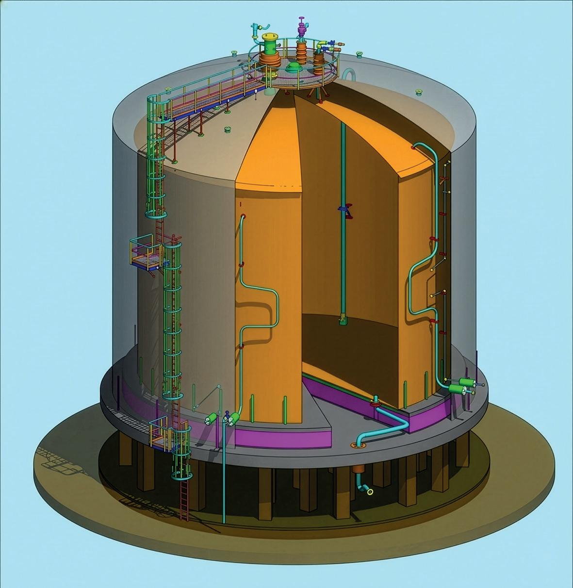
LIN is stored at -320°F under low pressure, typically ranging from 2 to 5 psig. A typical LIN tank (see Figure 1) consists of a double-wall, double-roof tank with a stainless steel inner tank and a carbon steel outer tank. Both the inner and outer tanks are anchored to resist the uplift from the internal pressure. To help keep the LIN at temperature, the inner tank rests on load-bearing
cellular glass insulation, and the annular space for the shell and the roof are filled with perlite insulation. The inner tank has external stiffeners to resist the pressure from the perlite. Process piping is installed in the annular space adjacent to the inner tank, enabling effective insulation while protecting the piping from external environmental conditions. The tank is typically elevated on a ‘table top’ foundation that is 10 to 12 ft above grade. The foundation is designed as either piles that end in a pile cap or as a double-slab concept with columns separating the two slabs. The elevation provides liquid head to the external pumps.
Held back by legacy
Historically, LIN tanks were designed such that they could later be converted to liquid oxygen (LOX) tanks. The prevailing thought was that this design would give owners flexibility to respond to increased LOX demand
in the future, but the demand never materialised. However, the LOX-related design requirements have continued to be applied to LIN tanks by being carried forward in today’s specifications.
The dual design aspect of LIN tanks required that they meet the more stringent requirements to store LOX. Namely, this meant that anything containing organic (combustible) materials could not be used in or around the tank. While oxygen does not combust, it does act as an accelerant if there is a fire present. Some examples of this impact are:
n Fibreglass insulation had to be replaced with more expensive and less effective ceramic insulation because of the flammable glue binders in the former option.
n Asphalt interleaving in the cellular glass load-bearing insulation had to be changed to more expensive and difficult to handle fibreglass woven cloth.
Another impact of these legacy design criteria is that a resilient blanket could not be used to reduce the external pressure from the perlite insulation. Over time, the perlite pressure grows, easily exceeding 100 lb/ft 2 , leading to tanks requiring extensive internal stiffening, often necessitating a stiffener at every ring. These examples of legacy constraints have limited flat-bottom LIN storage tanks to a maximum capacity of approximately 10 000 m 3 (2.64 million gal.).
Charting a new path
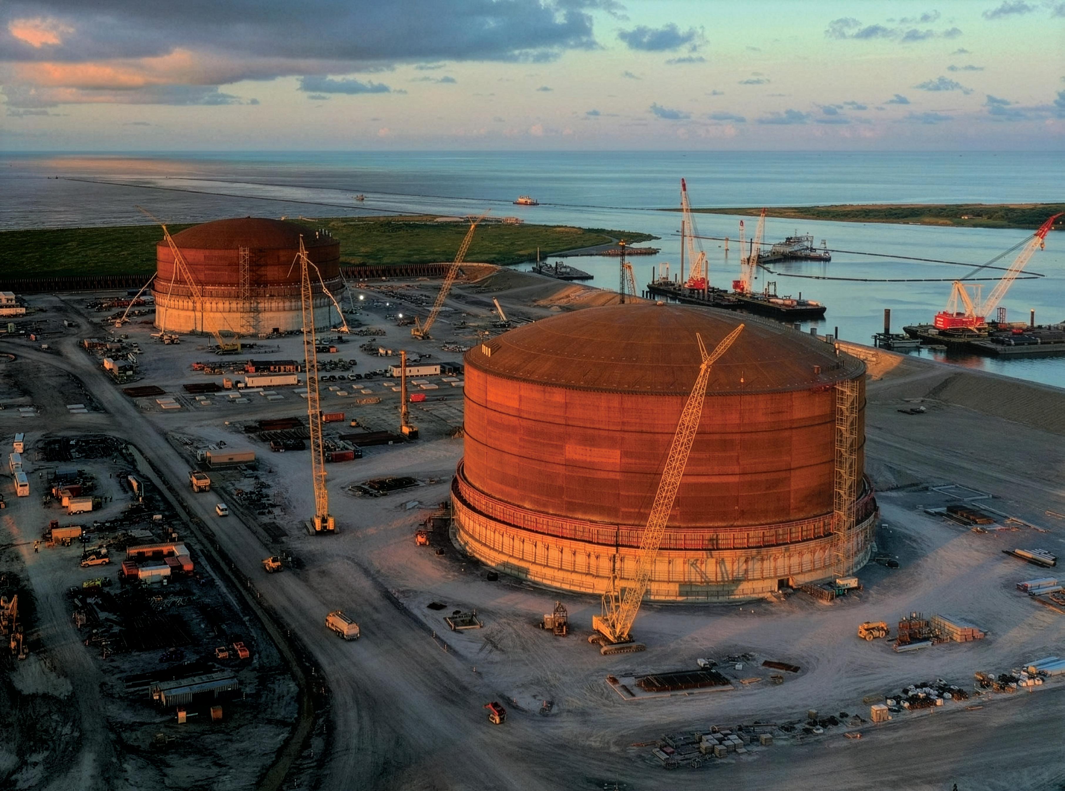
CB&I recently completed the construction of a LIN storage tank with a capacity of 22 400 m 3 , making it the largest LIN storage tank in the world. The tank supports a new semiconductor fabrication facility in Texas, US. Previously, CB&I had constructed a 10 000 m 3 LIN storage tank that was considered the world’s largest. To achieve this drastic increase in storage volume for a single LIN tank, CB&I collaborated with the LIN supplier to solve the many challenges necessary to make this tank a reality. CB&I’s expertise in design and
construction of large cryogenic storage tanks, such as LNG and ammonia tanks, provided the foundation for developing innovative solutions that enable larger - volume LIN storage.
The primary design challenge involved the stiffening of the inner shell against the perlite pressure. With a tank diameter of 117 ft and a height of over 86 ft, the perlite pressure would exceed 150 lb/ft 2 . Conventional stiffening would have necessitated thicker rings and multiple stiffeners on several of the upper rings. CB&I identified a resilient blanket solution that was acceptable to the client, allowing the perlite pressure to be reduced by more than 80%. While this configuration eliminated the majority of the stiffeners and allowed thinner shell plates to be used, it introduced a secondary complication. To use the resilient blanket, the inner tank stiffeners were required to be installed on the inside of the inner tank, instead of the customary exterior arrangement used to facilitate cleaning (how CB&I addressed the cleaning issue is discussed later in this article).
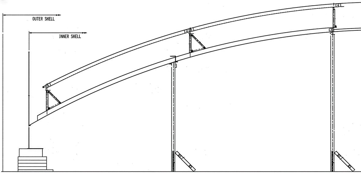
Another design challenge involved the roof selection and the placement of the roof at height. Typically, LIN tanks use a lap-welded, self-supporting dome roof for both the inner and outer tanks, with each roof placed using a crane. However, the size of this tank required a different solution that involved ring girders and radial rafters. Additionally, the reach of a crane required to lift and place such a large and heavy roof made the traditional installation method impractical. CB&I designed the inner roof to have externally framed girders and rafters fabricated from stainless steel to meet the temperature requirements for LIN service. The outer tank was designed with internally framed rafters and girders made from carbon steel.
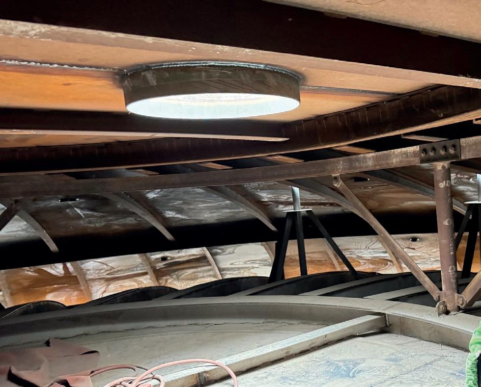
To install the roofs at the top of the tank, CB&I used a variation of its roof air raise method. In 1960, the company developed the air raise method that allows large dome roofs to be fully constructed inside the tank shell while at grade. The area under the roof is then pressurised, pushing the roof to the top of the shell. The difference with this tank is that there were two roofs to install: the inner roof and the outer roof. The solution is a ‘piggyback’ air raise. First, the inner roof was constructed at grade, inside the inner tank (see Figure 2). Temporary supports were placed on top of the inner roof, and the outer roof was then constructed, as shown in Figure 3. Special care had to be taken to ensure that the stainless inner roof did not receive carbon contamination from the outer roof construction. The roofs were air-raised together in a safe and seamless operation. In-fill pieces were then used to complete the section between the portion of the outer roof that was air-raised and the outer shell. Once the outer roof was completed and was fully supported by the shell, the temporary supports between the two roofs were removed.
Figure 1. Typical LIN tank configuration.
Figure 2. 'Piggyback' concept.
Clean, elevated
Traditional LIN tanks have always demanded an elevated level of cleanliness above what is required for other cryogenic stored liquids. The typical cleaning procedure involves the following process:
n Mechanical cleaning to remove large debris.
n Solvent cleaning to remove oil/grease deposits.
n Detergent cleaning.
n Potable water rinse.
n White light inspection for any visible contaminants.
Current semiconductor fabrication processes require a more stringent cleaning procedure and acceptance criteria. Ultra-pure and ultra-clean LIN is critical to ensure proper operation of the entire facility. Accordingly, elevated cleanliness requirements are necessary for all associated LIN storage. A black light inspection must be performed after the white light inspection. If the black light fluoresces on anything, it must be cleaned again. Additionally, the amount of fibres left behind from the cleaning cloths is a concern. For high-purity applications, the acceptance criteria require fibres to be smaller than 1 mm in size and total residue to be less than 50 mg/m 2 of the cleaned surface, which is half the amount typically permitted. CB&I successfully demonstrated to the client a cleaning methodology that met these strict requirements.
Conclusion
Larger LIN storage tanks provide a cost-effective solution for new semiconductor fabrication plants and allow for a smaller overall footprint and reduced land use. However, new technology solutions must be implemented to make the storage tank feasible.
There has been a shift in storage solutions to accommodate larger volumes of LIN. It is important for clients and owners to work with knowledgeable partners as they navigate the changes necessary to meet this demand and move beyond legacy LIN tank design and construction requirements.
Figure 3. Temporary roof supports.
Cody Falcon, ABB Energy Industries, explores how LNG terminal operators can utilise automation to ensure facilities are optimised.
Across the LNG terminal sector, operators face growing pressure to increase throughput, improve energy performance, and provide greater emissions transparency.
Global LNG demand is expected to continue rising as countries seek flexible, lower-carbon energy supply options. As utilisation increases and new capacity comes online, terminals are being asked to operate more efficiently while upholding the industry’s highest safety and reliability standards.1
Many LNG facilities are now operating closer to their technical and commercial limits than at any point in recent memory. At the same time, electrification is reshaping plant power architectures, experienced personnel are retiring, and many terminals operate in remote or infrastructure-constrained environments.
In this environment, terminal optimisation is no longer about incremental tuning alone: it is about building operating systems that are resilient, integrated, and progressively more autonomous.
The terminal as an interconnected operating system
An LNG terminal is not a collection of isolated assets. It is a tightly coupled operating system that connects feed gas conditioning, liquefaction or regasification, storage tanks, boil-off gas compression, marine loading, utilities, and power infrastructure.
A disturbance in one area can quickly propagate across the facility. A slight drift in mixed refrigerant composition can reduce liquefaction efficiency and constrain throughput. Instability in boil-off gas compressors can affect tank pressure and loading schedules. Variability in regas send-out can create downstream pipeline constraints that require rapid adjustment. In electrified facilities, voltage disturbances or load imbalances can influence compressor speed control and overall process stability. These are not isolated issues; they are examples of how local disturbances can cascade through an interconnected system and affect plant-wide performance.
Optimisation in LNG typically centres on three interconnected value levers: production, cost, and margin. Production levers focus on maximising throughput within compressor, thermal, and mechanical constraints. Cost levers address energy efficiency, maintenance strategy, and workforce productivity. Margin levers depend on availability, production assurance, and contractual performance. Even small gains matter at scale. A modest reduction in specific energy consumption or labour intensity can materially lower cost per ton across multi-train facilities producing millions of tons per year. Likewise, disciplined reliability engineering and contingency planning directly protect revenue and asset life.
Yet despite extensive installed automation, many LNG terminals still rely on manual retuning during transient states such as startups, shutdowns, and rapid demand shifts. In these moments, operators often move to conservative setpoints to preserve stability, leaving the plant below its optimal operating envelope for longer than necessary. The opportunity lies in narrowing the gap between theoretical capability and real-world performance.
Moving beyond conventional automation
Most modern LNG facilities are highly automated. Distributed control systems, safety instrumented systems, and advanced process control are standard. However, automation alone does not guarantee optimal performance. The next step is a structured progression toward higher operational maturity.
For many terminals, the first opportunity is to maximise the value of existing automation. Advanced process control and optimisation can reduce variability and improve stability. In liquefaction, this includes balancing trains against real-time efficiency and constraints, optimising refrigeration cycles, and managing feed gas variability. In regasification terminals, the same principles apply to vaporiser control, tank pressure stabilisation, and coordinated send-out.
However, startup, shutdown, and abnormal condition handling often remain heavily dependent on operator experience and intuition. Compared to other process industries, LNG operations can lag in procedural automation during transient states. Encoding operating procedures into structured, digital workflows can reduce variability, improve repeatability, and strengthen safety performance.
Integrating process, power, and operational data
The next layer of maturity is data integration. LNG terminals generate vast amounts of operational data, but information often remains fragmented between control systems, electrical platforms, and maintenance tools. When these domains are disconnected, diagnosing performance issues becomes slower and more reactive.
Modern architectures increasingly unify automation and electrical control within a common operational data environment. This is becoming especially important as LNG facilities adopt electrified compression and all-electric plant designs.
In new all-electric LNG plants, integrated automation and electrical architectures show how coordinated power management can improve both stability and energy performance. Large electric-drive compressors require precise alignment between electrical systems and process control to maintain reliable operation.
Early examples of this model are already emerging in large scale LNG developments. One is ADNOC’s Ruwais LNG project, the first LNG export facility in the Middle East designed to run on clean power.2 ABB’s automation, electrical, and digital solutions will support efficiency and safety at the site, including a microcontroller-based electrical control and monitoring (ECM) system that gives operators real-time visibility and control of electrical assets. This visibility enables faster fault detection, improved load optimisation, and more effective power management while helping reduce unplanned downtime.3
This matters because even minor disturbances in power quality can influence compressor performance and refrigeration efficiency. Integrated electrical monitoring enables earlier fault detection, better load distribution, and more consistent operating conditions across multiple trains. As electrification becomes more common, the ability to manage process and electrical behaviour together is becoming a defining capability of modern terminal operations.
Power management also introduces new operational demands. Electric-driven liquefaction systems depend on stable grid connections or dedicated power infrastructure capable of supporting large, rapidly changing loads. Monitoring voltage stability, harmonic distortion, and transient events is essential to protecting equipment and preserving production reliability. When electrical and process systems are managed together, operators gain a clearer picture of how energy consumption, compressor behaviour, and process conditions interact. This visibility improves both operational efficiency and long-term asset reliability.
SOLVING TODAY’S OPERATIONAL CHALLENGES
WITH AUTONOMOUS-READY SOLUTIONS
Built on 100+ years of domain expertise and powered by AI, simulation, and advanced process control, ABB Digital Solutions help industrial facilities transition from automation to autonomy.
See solutions, use cases, and next steps.
Building operational intelligence and autonomy
Workforce dynamics add another layer of urgency to terminal optimisation. Experienced operators are retiring and recruiting for remote or offshore facilities remains challenging. Digital twins, high-fidelity simulators, and guided operating procedures allow teams to rehearse complex transitions and abnormal scenarios without putting the live plant at risk. They capture operational knowledge in a structured form and reduce variability between shifts.
Autonomy in this context is not about removing people from operations. It is about elevating their role by reducing time spent on repetitive adjustments, manual reconciliation, and routine decision support.
Operational autonomy typically evolves along two parallel paths. The first is production. Reinforcement learning and hybrid modelling can help identify optimal operating envelopes within defined constraints, reducing variability and improving energy efficiency. These techniques continuously evaluate conditions, recognise patterns in process behaviour, and recommend adjustments that maintain stability while maximising throughput. In LNG facilities, where compressors, refrigeration cycles, and feed gas composition interact dynamically, even small improvements in control precision can deliver measurable gains.
The second path is maintenance. Many terminals still rely heavily on calendar-based maintenance strategies. While effective in protecting equipment, this approach can also drive unnecessary shutdowns and inefficient resource use. Shifting toward condition-based maintenance protects critical assets such as compressors, pumps, and electrical systems, while reducing avoidable intervention.
Modern asset performance management platforms combine rule-based monitoring, physics-based models, and data-driven analytics to detect earlier signs of degradation across the probability-of-failure curve. Identifying emerging bearing wear or seal instability early, for example, can prevent downstream impacts on refrigeration performance, availability, and production targets.
Managing storage, marine interfaces, and terminal logistics
Equipment reliability is only one part of sustained terminal performance. Optimisation must also reflect the realities of storage and marine operations.
Tank pressure stability under changing production and loading conditions is central to safe, efficient performance. Boil-off gas generation shifts continuously with temperature, cargo movement, and process conditions. Coordinating boil-off gas compression with liquefaction or regasification rates therefore requires predictive insight and precise control. At the same time, integrated alarm rationalisation and safety analytics ensure genuine risk signals are not buried beneath nuisance alarms.
Marine interfaces add another layer of complexity. Cargo loading windows are commercially critical, and delays can have significant contractual consequences. Variability upstream can quickly ripple into scheduling disruptions if storage levels, process stability, and marine operations are
not well coordinated. Real-time visibility across process, storage, and marine domains helps operators manage these interactions and maintain reliable loading performance.
Storage infrastructure itself presents additional operating constraints. LNG tanks must accommodate thermal expansion, pressure variation, and dynamic inventory changes as cargoes arrive or depart. Monitoring temperature gradients, liquid levels, and vapour conditions helps operators maintain safe storage conditions while making the best use of available capacity. Integrating tank monitoring into the broader terminal automation architecture provides a more complete picture of facility performance and helps teams anticipate constraints before they become production issues.
As autonomy increases, safety remains constant. AI-enabled analytics can recommend actions or flag emerging risks, but safety instrumented systems must continue to operate under rigorous engineering standards and human oversight. Clear separation between advisory intelligence and safety-critical control is essential. Ultimately, operator trust will determine how far higher levels of autonomy are adopted in practice.
Connecting terminal operations with enterprise performance
Finally, terminal optimisation increasingly extends beyond the control room. When operational data connects with supply and cost and demand systems, operators can evaluate trade-offs between throughput, energy consumption, maintenance timing, and contractual commitments in real time. In carbon-constrained markets, digital systems also support emissions tracking and energy optimisation strategies that align operational performance with sustainability objectives.
This is where automation becomes more than a local control capability. It becomes a strategic performance lever, supporting both operational and commercial decision-making.
Full autonomy is not the immediate goal for LNG terminals. The goal is consistent, predictable performance within defined operational envelopes. The most resilient facilities will take a structured approach: stabilising and maximising existing automation, integrating operational data, capturing workforce expertise, and applying intelligent analytics where they deliver measurable value.
For LNG operators, optimisation and automation are not abstract ambitions. They are practical responses to cost pressure, electrification, workforce change, and market volatility. In the next phase of LNG terminal optimisation, competitive advantage will not come from isolated control improvements, but from operating the terminal as an intelligent, integrated, and increasingly autonomous system.
References
1. 'Gas 2025' International Energy Agency, (IEA), https://www.iea. org/reports/gas-2025
3. 'ABB integrated solutions to support ADNOC’s all-electric Ruwais LNG facility', ABB, (5 November 2025), https://new.abb.com/news/ detail/130262/abb-integrated-solutions-to-support-adnocs-allelectric-ruwais-lng-facility
Bram Sijbers, ROSEN, discusses how digitalising tank inspection data can allow for improved predictive integrity management, to ensure the safe and efficient operation of aboveground storage tanks.
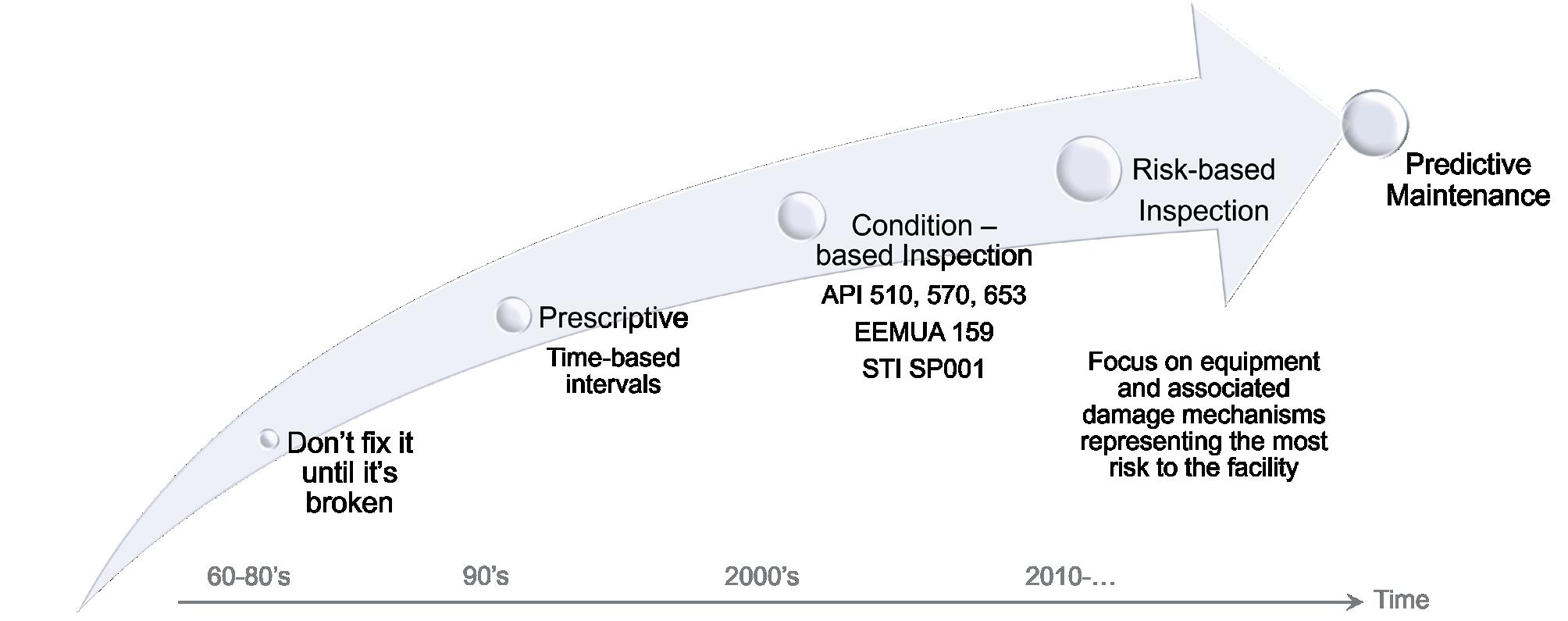
Ensuring the integrity of aboveground storage tanks is fundamental in the oil and gas industry, including petrochemicals, bulk storage, and processing. The evolution of tank integrity management has been driven by one decisive factor: the quality and availability of inspection data. In the industry’s early decades, limited insight into tank condition caused operators to rely on the reactive philosophy of ‘do not fix it until it is broken.’ As inspection technologies advanced throughout the 1990s, the sector adopted prescriptive, time-based inspection intervals, which brought structure but treated all tanks uniformly.
Further improvements in data resolution and coverage enabled the industry to progress to condition-based inspection, supported by standards such as API 653 and EEMUA 159. This approach allows decisions to be made on the actual condition of assets rather than on schedules alone. This data maturity ultimately paved the way for risk-based inspection, enabling operators to quantify the probability and consequences of failure and to tailor their high-resolution, accurate, and structured data collected consistently, integrated efficiently, and analysed intelligently. Predictive integrity strategies depend on data quality as much as data quantity, connecting information across inspections, systems, and operational contexts to forecast degradation before it occurs.
Redesign of digital tank inspection and reporting workflow
The next leap forward in tank integrity will only be possible if the industry transforms how inspection data
is generated, processed, and delivered. With this in mind, ROSEN has undertaken a fundamental redesign of its Digital Tank Inspection and Reporting Workflow, creating a foundation built for the predictive era.
For decades, inspectors relied on pen and paper to record findings and sketch observations, while photographs were taken separately and often stored on cameras, and later matched manually with handwritten notes.
ROSEN is in the process of replacing this traditional approach with fully digital, AI-empowered data collection on a tablet with voice-to-text recognition, allowing inspectors to record visual findings, capture photographs, and enter observations directly into one integrated database. This shift not only improves accuracy, but ensures that every photograph and comment is automatically linked to the correct tank component and inspection location.
Figure 1. How tank inspection philosophies have matured over decades – improving decision making, reducing risk, and enabling modern integrity management practices.
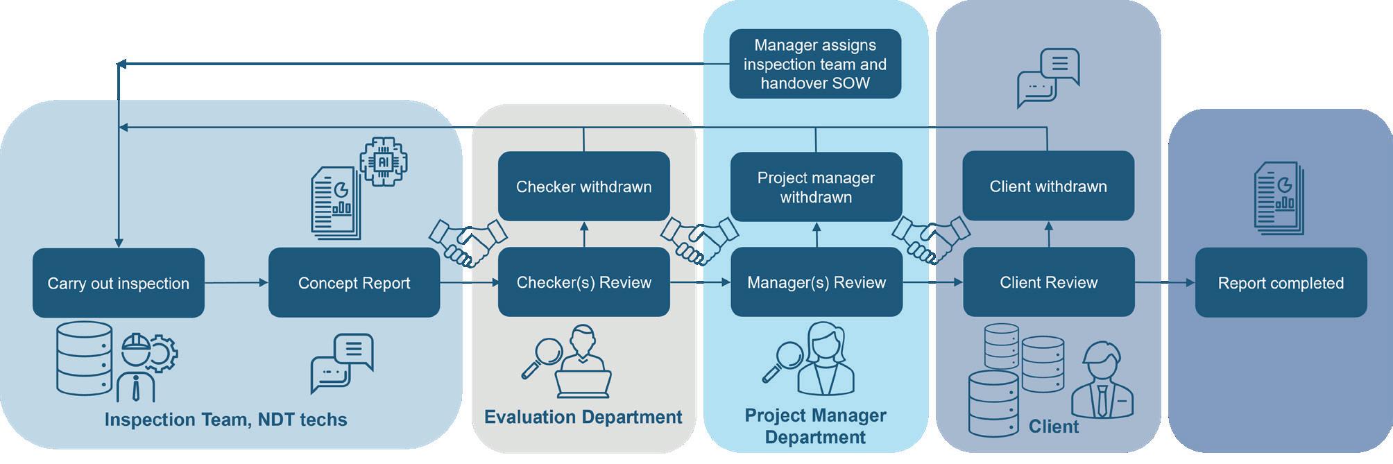
Figure 2. Structured workflow ensuring transparency, consistency, and efficient collaboration from initial inspection to final report delivery.
Need maximum process e ciency? We supply the measurement technology.
SCAN HERE to learn more
Oil and gas resources go through many crucial process steps before they become valuable, state-of-the-art products. With our level and pressure measurement technology, you can fully develop their potential. Utilising our sensors, you can achieve maximum e ciency and reliability in every phase of production, delivering top quality performance, even under the harshest conditions.
Everything is possible. With VEGA
AI-supported reporting and project transparency
While this improves digital data collection, the reporting phase often remains a bottleneck. Inspectors still spend hours or days converting field data into clear, structured reports. Inconsistent formatting, manual photograph placement, and repeated data entry slow the process and increase the risk of errors. Comparing current inspection results with previous data sets is also difficult when reports vary in style and detail. To address these challenges, ROSEN has developed dedicated reporting software for tank inspectors that is specifically designed around API 653 and EEMUA 159 requirements. AI plays an important role in the system by supporting automated data structuring, photograph classification, consistency checks, and automatically translating reports into any language. Through direct integration with the tablet and the captured visual inspection, the software streamlines the entire reporting workflow. Every photograph and observation recorded onsite automatically flows into the correct section of the final report, eliminating repetitive administrative steps that traditionally slowed the process.
A key advantage of the system is the increased project transparency it provides to the project team. The project manager in the office has full access to the software and ongoing inspection data, allowing the project’s status to be tracked in real time. It is clear to see which inspection tasks have been completed and which sections still need to be inspected. This improved visibility and coordination between field teams and office teams, as well as with the asset owner, ensures smoother planning and quicker responses to unexpected findings.
Enabling predictive and risk-based integrity management
The time savings are substantial, as high-resolution photographs are automatically organised, and summaries and recommendations are generated based on input captured during the inspection. With AI-driven
processing, reports that once took several days to compile can now be completed in hours, allowing asset owners to receive critical information almost instantly.
AI-assisted interpretation transforms raw inspection data into structured information, supporting better decision-making and highlighting potential areas of concern more clearly than manual methods.
This new workflow also strengthens compliance and traceability. Every action, from entering data on the tablet to generating the final report, is tracked and logged. Reports are stored in a structured digital archive, making them easy to retrieve for regulatory reviews, internal audits, and long-term integrity planning.
This solution brings true digital integration to tank inspection processes by combining a modern, tablet-based field workflow with a purpose-built reporting platform, AI-supported automation, and real-time project oversight for office teams. It ensures that valuable information collected onsite is accurately, consistently, and efficiently transformed into high-quality reports. This digital approach supports more effective and safer integrity management of aboveground storage tanks.
This initiative was conceptualised collaboratively across ROSEN, with engineers looking for ways to innovate, improve efficiency, as well as listen to client feedback. Digitised data enables faster and more accurate comparisons between previous and future inspections, corrosion rate calculations, and risk-based inspections (RBI). The power of predictive analytics with RBI is only partly realised today. In the future, with more digital data and AI, it will become more accurate and powerful. For operators, this will be a valuable tool for identifying changes over time and prioritising repairs based on actual conditions. As more inspection cycles are added to the digital archive, asset owners will have a clearer, more complete picture of the tank’s lifecycle performance, which will support predictive tank maintenance.
Looking ahead: building the digital tank lifecycle
Looking ahead, the digitisation of tank inspection data will open the door to even greater advantages for asset owners and operators. With data captured in a structured, readable format, integration with customer systems, such as integrity management platforms, becomes significantly easier. This reduces manual handover efforts and ensures that inspection results can immediately support maintenance planning, risk assessments, and operational decisions.
Ultimately, this new data platform which combines digital field data, structured data integration, and AI-supported reporting and analytics, will provide a foundation for predictive insights and smarter long-term integrity strategies. This will further raise the standard for the safe and efficient operation of aboveground storage tanks.
Figure 3. Integrated digital data collection in the field reduces manual steps and improves consistency across the inspection workflow.
William Fazackerley, Emerson, explains how wireless ultrasonic metal thickness detectors can provide an answer to the problem of rusting storage tanks.
When oil and chemical companies experience safety and hazmat incidents, such news is rarely broadcast, but in some cases the effects are impossible to hide. For example, in a notable incident from 2014, 10 000 gal. of a coal cleaning solution were accidentally released from a corroded tank, with the solution entering a nearby river. An extensive technical analysis found that the tank had not been internally inspected for at least 10 years before the incident. Due to these types of incidents, operating companies, their surrounding communities, and insurers are very concerned that storage tanks are constructed properly and inspected at prescribed intervals to verify that they are suitable for their intended use and remain that way over their service life. The American Petroleum Institute (API) has
published a series of interrelated standards and practices that are applied extensively in this and a variety of similar industries:
n API Standard 650, Welded Tanks for Oil Storage, 13th Edition: “This standard has been published to ensure the safety, sustainability, and environmental performance of oil storage tanks. The updated standard will help continue operational excellence and trust between operators and manufacturers.”
n API Standard 653, Tank Inspection, Repair, Alteration, and Reconstruction: “This standard covers steel storage tanks built to API 650 and its predecessor API 12C. It provides minimum requirements for maintaining the integrity of such tanks after they have been placed in service and addresses inspection, repair, alteration, relocation, and reconstruction.”
n API Recommended Practice 580, Risk-Based Inspection:
“The purpose of this document is to provide users with the basic minimum and recommended elements for developing, implementing, and maintaining a risk-based inspection (RBI) program. It also provides guidance to owner-users, operators, and designers of pressure containing equipment for developing and implementing an inspection program.”
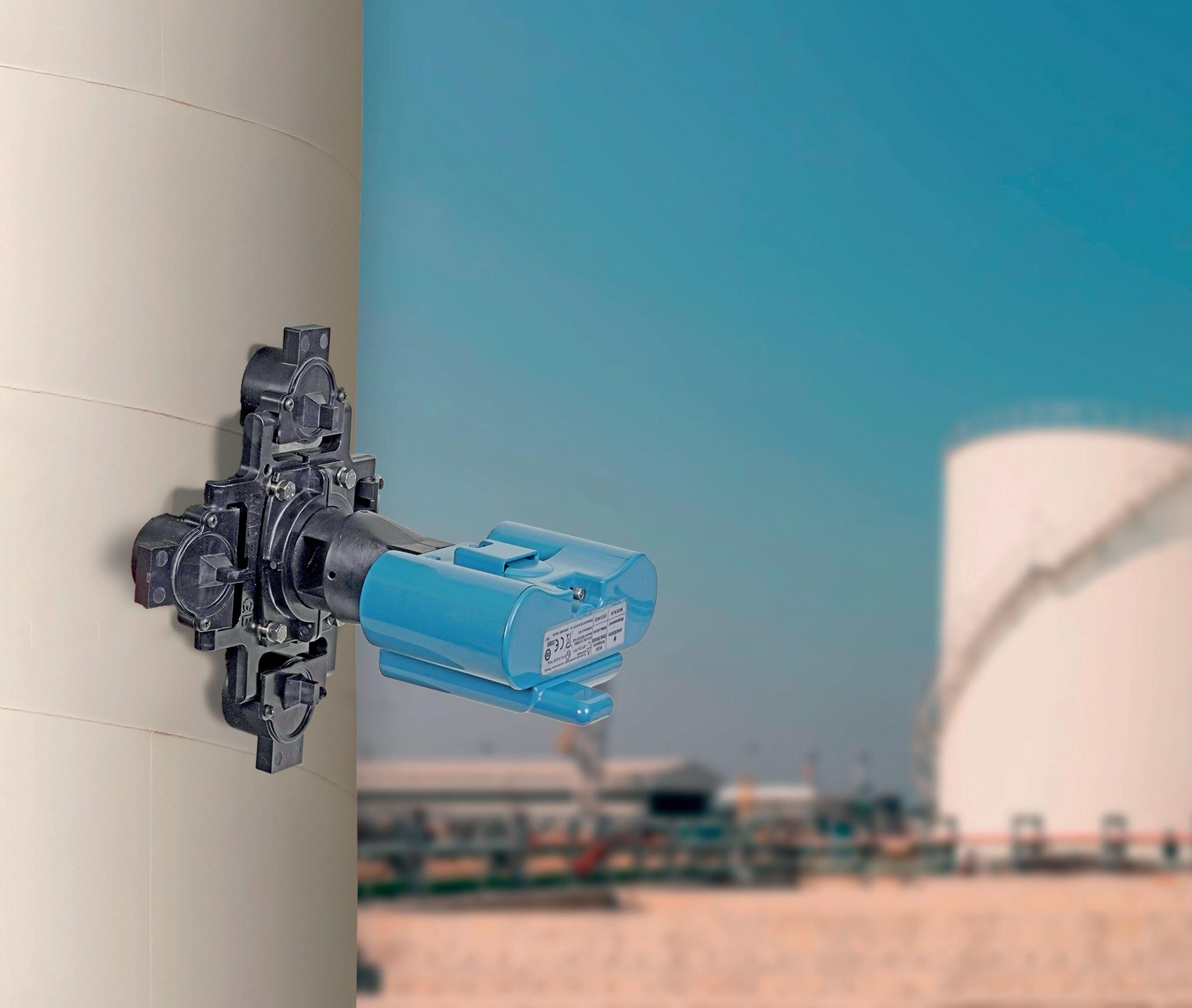
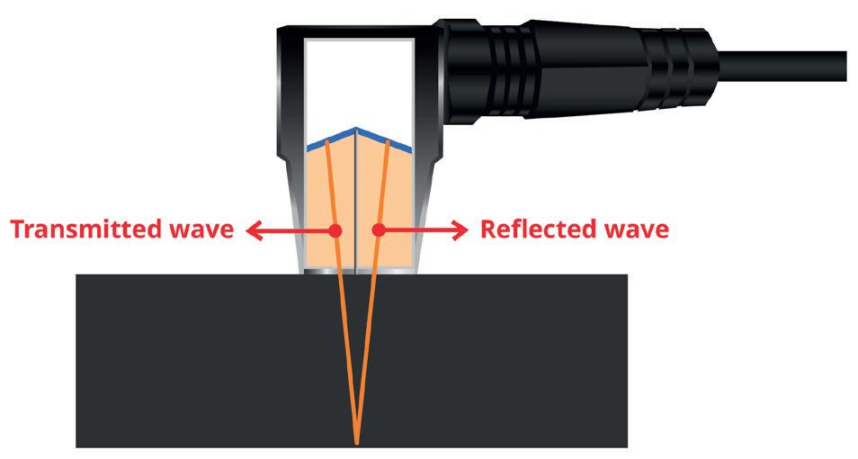
Figure 1. Ultrasonic thickness instruments time the speed of a sound pulse passing through the metal. Calculating thickness depends on knowing the speed with which the pulse passes through the specific alloy.
Figure 2. Emerson’s Rosemount Magnetic Vessel Mount is compatible with Rosemount Wireless ET210, ET310, and ET310C Corrosion and Erosion Transmitters. Placement can be permanent, or these transmitters can be unlatched when necessary for easy removal and placement elsewhere.
3. Data from permanently mounted transmitters can be collected and historized for ongoing analysis.
Inspections are important but insufficient
Implementing and practicing the requirements of these standards is absolutely critical. However, a facility should not consider these standards exhaustive and assume no other monitoring is necessary. There are many potential conditions that could develop that are capable of causing incidents, even in an environment where inspection protocols are practiced scrupulously.
In addition, inspections are only as good as the skills of the inspector, so some conditions may go undiscovered. Moreover, internal tank inspections are highly complex since they can only be done when a tank is empty, and they include extensive requirements for confined space entry. While such inspections may fulfill regulatory requirements, they may not provide comprehensive insight as to the actual condition of tank walls, particularly in an environment where operational conditions are subject to change between routine checks.
Keep in mind, when many tanks were built, plants assumed that the products they were handling had consistent and predictable characteristics, and when matched with appropriate metallurgy, there was no reason to expect elevated corrosion. This expectation was fine until product variability at all levels became commonplace, where chemicals from one source might differ significantly from another. A batch today might have subtle but critical differences to a batch from last week, resulting in different corrosiveness characteristics. Alternatively, a plant’s output may change to accommodate different market demands.
Questions often remain:
n A given tank passed its last inspection, but where the contents are now more corrosive, is the metal still thick enough to last another few years, or are there sections ready to rupture the next time the tank is filled to its limit?
n What technologies are available to determine if corrosion has eaten too much of the metal away for safe operation?
Approaches for inferring the effects of corrosion have evolved, with various solutions adopted over the years. However, a technology that is able to measure actual metal thickness from the outside without penetration is the ultimate objective, and this is now possible.
A positive approach
External tank inspections are easier and can be performed at any time under any conditions. The goal in this situation is measuring actual wall thickness, so the technology applied should ideally provide this measurement directly rather than inferring what metal is being lost. Tank inspectors often use hand-held ultrasonic thickness detectors that measure by timing an ultrasonic pulse as it passes through the metal and is reflected from the back side (Figure 1).
In the hands of an expert technician, such readings can be very accurate, but they require the technician to be at the measurement location, which might be difficult or dangerous to access. They also have no ability to provide historized data. Some units can record multiple measurements over
Figure
EFFICIENT & PRECISE MARINE LOADING
SYMETRIC NEO sets a new standard in marine loading arms by combining electric drives with a lightweight, self-supporting design. The use of standardized electric drives delivers precise, linear movement enabling accurate and reliable operation. This technology drives down both CAPEX and OPEX with its streamlined design, reduced material needs, fewer components, and a lean maintenance approach. The electric drive system eliminates the need for hydraulic components, reducing installation complexity and the risk of leaks, while supporting fast, efficient operation for green ammonia, CO₂, methanol, and a wide range of chemical and oil products.
The smart construction of SYMETRIC NEO means lower base loads on the jetty, further reducing structural costs. Installation is straightforward, with fewer parts and no need for hydraulic lines or reservoirs. Proven SVT swivel joints and a reliable LiFePO₄-based UPS ensure operational safety and continuity.
SYMETRIC NEO’s intuitive joystick control enables fast, precise operation, protecting vessel manifolds and reducing the risk of delays or costly repairs. Short connection times and smooth handling help maximize loading efficiency and keep operations on schedule.
Maintenance becomes significantly easier with SYMETRIC NEO. Electric drives mean less downtime and faster servicing, as electric components are simpler to replace and maintain than hydraulic systems. Maintenance routines are streamlined and less complex, allowing teams to focus on core activities and minimize operational interruptions.
Choose SYMETRIC NEO for a cost-effective, reliable, and future-ready marine loading solution—ideal for green ammonia, CO₂, methanol, chemical, and oil products.
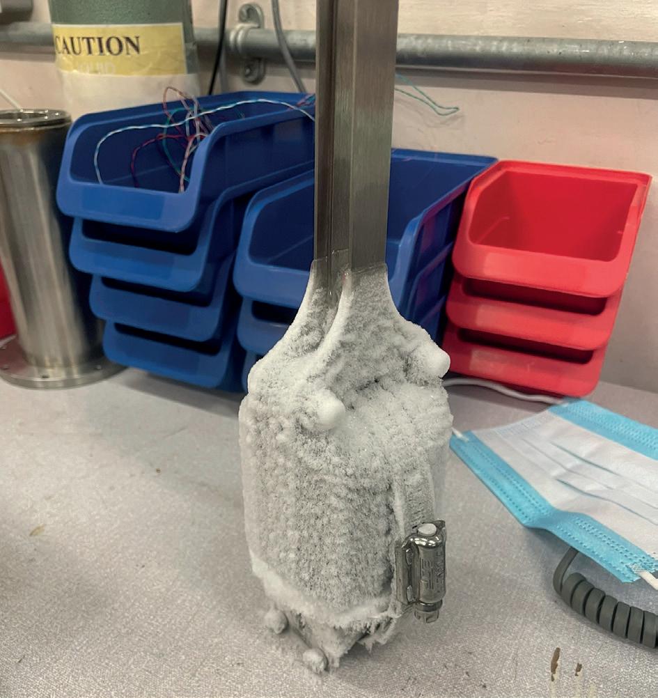
Figure 4. LNG transfers are critical, so monitoring corrosion of pipelines and tanks is necessary to ensure high availability. Rosemount™ Wireless ET410 Corrosion and Erosion Transmitters operate even at LNG temperatures.
time, but there is no assurance that the reading location is exactly the same in each case.
A practical and effective approach
The ultrasonic measurement technique is excellent for this application, and it is most effective when a single sensor can be left in place for a period of time, while sending data via a wireless network. This overcomes the drawbacks of intermittent checks.
In the first instance, a series of locations on a tank must be selected for monitoring. Generally, these should cover a variety of positions at different depths, and even on the roof. Areas where turbulence is common near inlets and outlets should be high on the list as fluid movement increases corrosion. Placement flexibility is supported by two capabilities.
When wireless transmitters have self-contained power sources, there is no need for any cabling. Mounting challenges are also minimised by using magnetic mounts (Figure 2), allowing positioning without welding or other tank modifications. These transmitters can handle wide temperature ranges, covering cryogenic temperatures in LNG applications, and high temperatures up to 600°C (1112°F). Magnetic mounts are limited to 270°C (520°F).
Second, transmitter data is collected via the facility’s WirelessHART network, using the same infrastructure as the level and other instruments frequently installed on storage tanks and throughout tank farms. Once transmitters are added to the network, monitoring begins immediately. Once mounted, each transmitter provides a baseline wall thickness for its location. Going forward, it provides repeatable measurements by recognising changes as little as 2.5 µm (0.0001 in.), making it possible to observe metal loss over time as it happens. Generally, the transmitters send an
update every 12 hr, but this is adjustable down to as frequently as every 15 min.
The data is then collected, historized, and subjected to whatever statistical analysis the facility decides is useful (Figure 3). Some companies are satisfied with monitoring wall thickness to ensure equipment condition is well within safe limits, with alarms triggered when thresholds have been crossed. Others perform deeper analysis, correlating rates of metal loss with specific process conditions, often matching against data from resistance probes to correlate corrosive conditions with metal loss rates. Software platforms are capable of providing the desired level of analysis.
This information empowers engineers to move beyond simple detection and perform accurate root cause analysis, schedule predictive maintenance, and adjust the amount and type of corrosion inhibitors. It also arms staff with confident calculations of assets’ remaining life so they can optimise turnaround schedules, enhance safety, and drive profitability.
Ensuring facility availability
One of the most complex and costly tank and terminal operations is transferring LNG. The combination of cryogenic temperatures, highly hazardous product, and continuously shrinking product volume through boil-off means that maintaining safe and efficient operation is paramount. An incident resulting in containment loss due to corrosion can have negative effects, so monitoring is critical.
An LNG unloading facility in Asia depends on a 42 in. transfer line from its jetty to onshore storage and distribution section (Figure 4). This line is 120 m long and was equipped with several RosemountTM Wireless Corrosion Transmitters. These operate reliably in spite of the LNG temperature of -162°C (-260°F), even when encrusted in a layer of frost. This transfer line provides fast and reliable unloading, allowing for quick turnaround with minimal volume loss. High reliability here goes hand-in-hand with safety, causing the facility’s insurance carrier to reduce its premiums.
Future-proofing operations
Adopting modern corrosion monitoring techniques can be a major part of broader asset management programmes using continuous, automated, and repeatable data. This is much more effective than sporadic, manual, and variable measurements.
Real-time metal thickness monitoring should guide maintenance planning to maintain efficient production with lower operational expenses. Maintenance teams can become strategic analysts, facilitating high-value insights and improved data sharing with plant engineers and production planners. Corrosion specialists can optimise mitigation strategies, using data analytics to improve safety and efficiency.
Facilities can predict assets’ remaining useful life with higher accuracy by learning from historical data, revealing operational trends. Non-intrusive corrosion and erosion monitoring technologies provide insights unimaginable just a decade ago, allowing companies to maximise reliability, operate more safely, and perform more profitability in today’s competitive industrial markets.
Ajin Prasanthan, Dräger, Germany, outlines why a connected process can contribute to higher levels of occupational safety and greater operational efficiency.
There is an ongoing parallel in the oil, gas, and chemical industries. Tanks, silos, and similarly enclosed structures are inherently hazardous workplaces, and decades of regulatory development have created a comprehensive framework designed to prevent accidents. Yet, despite this extensive oversight, fatal incidents continue to occur every year worldwide.
Data from the US Department of Labor’s Bureau of Labor Statistics (BLS), specifically the Census of Fatal Occupational Injuries (CFOI), indicates that confined space incidents result in around 100 fatalities
each year in the US, nearly two deaths every week on average.1 In the UK, the Institution of Occupational Safety and Health (IOSH) reports that approximately 15 workers die each year in confined space incidents.2
Even when looking at a single sector, the scale of the problem becomes clear. The Marine Accident Investigation Branch reported, in reference to the Berge Mawson report (2025), that 257 enclosed-space fatalities occurred in the maritime industry alone between 1999 and 2023.3
The persistent risk of confined spaces
All of these deaths occur even though working in confined spaces, such as tank cleaning in the oil, gas, and chemical industries, are subject to particularly strict safety regulations internationally. In Germany, for example, work in such environments is regulated by DGUV Rule BGR 117-1 (‘Working in containers, silos, and confined spaces’), which defines requirements for risk assessment, rescue planning, and supervision. In the US, comparable provisions are established under OSHA Standard 1910.146, which regulates so-called “permit-required confined spaces.” This standard obliges employers to identify confined spaces, assess atmospheric and mechanical hazards, and implement formal entry-permit procedures before work begins.
Within this broader regulatory framework, additional technical standards govern the equipment used to protect workers from hazardous atmospheres. For instance, EN 529 in Europe and OSHA 1910.134 in the US specify requirements for the selection, maintenance, and use of respiratory protective equipment. The quality of supplied breathing air is likewise regulated, by EN 12021 in Europe and ANSI/CGA G-7.1-1989 in the US. These standards represent only a portion of a comprehensive safety system that combines regulatory oversight, technical requirements, and operational procedures, such as detailed risk assessments, atmospheric monitoring, and rescue planning.
Such extensive precautions are necessary because confined spaces present a unique combination of hazards. Workers may be exposed to toxic gases or hazardous substances, face the risk of explosions caused by flammable atmospheres, or encounter dangerously low oxygen levels. For this reason, plant safety management is responsible for ensuring that atmospheric clearance measurements are carried out by qualified gas analysts before any confined-space entry takes place.
Clearance measurement is performed to verify that the atmosphere inside a confined space is safe enough for workers to enter and perform their tasks. The air must be free of, or within acceptable limits for, hazardous substances, including toxic or flammable gases, and oxygen concentrations must remain within safe ranges. Measurement results must be carefully recorded, precisely documented, and clearly communicated to all personnel involved. This process is essential for maintaining a safe working environment and, just as important, preventing costly disruptions to operations. But the process is far from simple. Within the permit-to-work system it stands out as one of the most complex and resource-intensive steps, demanding careful planning, disciplined execution, and complete transparency.
On top of that, many companies bring in decades of their own experience working in confined spaces. Across the millions of confined-space entries carried out around the world each year, workers and safety managers are constantly asking the same questions:
n Which legal regulations apply to this specific work assignment? Are certified workers and proper devices available?
n Does everyone know their responsibilities?
n Are the necessary operating instructions available?
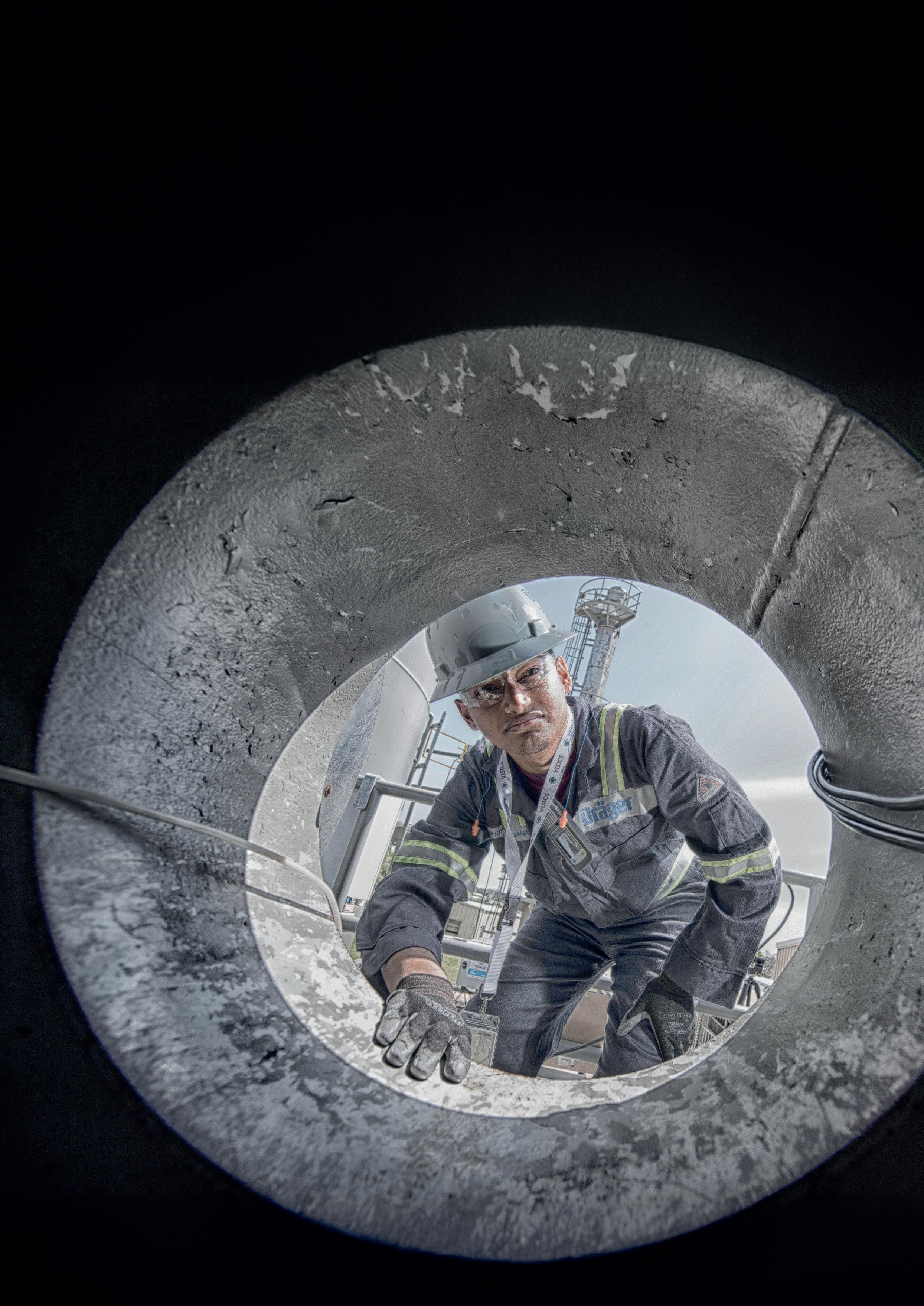
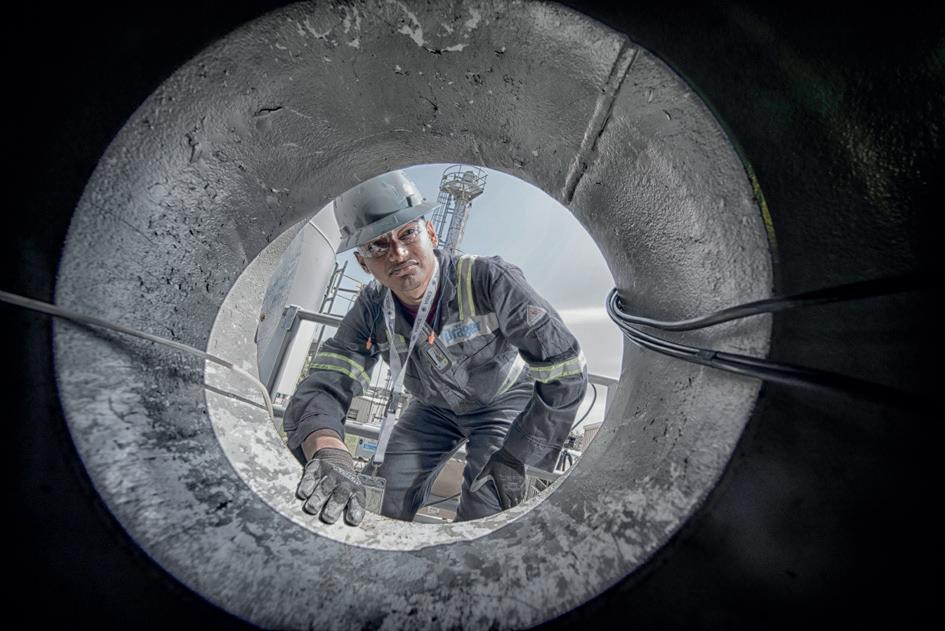
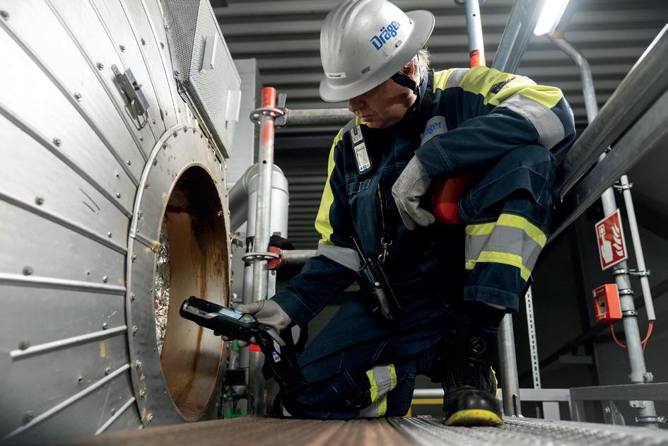
Figure 1. Every parameter is checked and every risk is controlled.
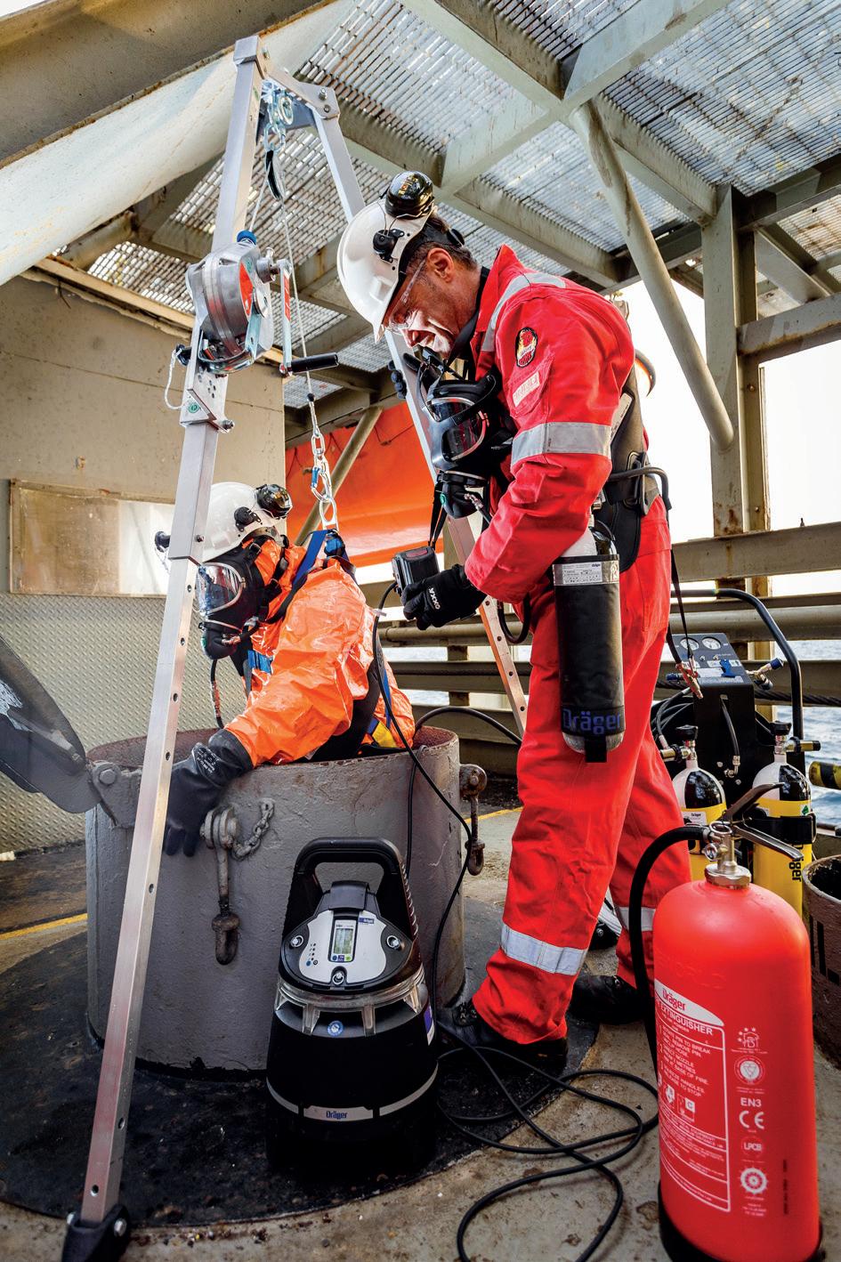
Figure 2. Safety in confined space: procedural rigour and PPE conformity.
n Have workers been trained regarding their individual activities?
n Have they been trained in the use of personal protective equipment (PPE)?
n What rescue plan is in place in case something goes wrong?
n Have the recommended measures been consistently thought through?
With all these safety considerations already made by regulatory bodies, companies, as well as workers, this begs the question: how can confined space entry and clearance management be improved?
Physical safety as a digital question
One possible answer lies in digital technology. Digitalisation can significantly improve safety in confined spaces because it replaces assumptions with transparency. When atmospheric measurements, permits, and safety checks are available in real time, supervisors and workers can make informed decisions instead of relying on a gut feeling. Integrating that information into operational systems also makes safety easier to track and manage as part of everyday operations.
Clearance measurement must follow a strict and systematic protocol to ensure the safety of workers, as well as precision, clarity, speed, and efficiency in the work process. Confined-space entry can only take place once the atmospheric conditions have been verified as safe. If this
verification cannot be completed as planned, it can delay project progress and lead to additional costs.
Operational inefficiencies in this process often arise from the documentation and communication required. Errors or misunderstandings when transferring measurement data, recording results, or communicating approvals can result in further delays due to corrections or repeated measurements. Reducing such interruptions is essential for maintaining on-site productivity, as downtime not only increases costs but can also affect a company’s reliability and reputation in future projects.
These interruptions can quickly slow operations on site. Downtime increases costs and can even affect how reliably a company is perceived on future projects. Any improvement or simplification of this process can therefore strengthen both safety and operational efficiency.
Connecting people, devices, and data
By enabling real-time information exchange between gas analysts, site safety managers, supervisors, and control room personnel, digital systems help ensure that measurement results are documented clearly and shared immediately with all relevant stakeholders.
One way to implement such a workflow is through integrated platforms that connect gas detection devices, mobile applications, and cloud-based data management. An example is Dräger Gas Detection Connect, a cloud-based platform designed to link portable gas detectors with field personnel and control-room systems.
Systems of this kind connect individual gas detection devices to a broader digital safety network via Bluetooth, for example; though other connectivity options exist. Portable detectors transmit measurement data, alarms, and device information via a mobile application to a central cloud platform, where the information becomes available in near real time. Supervisors and safety managers can access this data through a web interface, allowing them to maintain an overview of ongoing operations and respond more quickly if hazardous conditions arise.
Beyond real-time monitoring, the digital collection and storage of measurement data also creates a comprehensive record of safety-relevant activities. Measurement results, device status information, and event histories are stored centrally and later retrieved for auditing, documentation, or further analysis. This helps ensure regulatory compliance while also enabling organisations to identify patterns, investigate incidents, and improve future safety procedures.
The real advantage is not just the detector itself, but the connection between people, devices, and information. When gas detectors become part of a digital network, they contribute to a much clearer picture of what is happening across the entire facility.
This largely digitalised workflow reduces administrative effort for both gas analysts and control room personnel. It can also minimise unnecessary movement on site: by eliminating
manual data transfer and repeated trips between measurement locations and the control room, a single gas analyst may save up to 1.3 km of walking per day.
Many of the inefficiencies in traditional clearance measurement are simply the result of information moving slower than the work itself. When data flows directly from the field to the control room, those small but frequent delays disappear.
However, implementing digital systems for clearance measurement and gas detection often requires organisations to adapt their existing workflows. Real-time data collection, automated documentation, and connected devices cannot always be integrated directly into established procedures without adjustment. Many traditional processes in confined-space work were designed around manual documentation, physical permits, and sequential communication between different roles. Introducing digital tools therefore frequently requires companies to rethink how information flows between gas analysts, supervisors, and control room personnel.
Technology alone is not enough
For this reason, the transition to digitalised safety processes should be understood not merely as a technological change, but also as an organisational one. Workflows may need to be redesigned so that measurement data, approvals, and documentation can be handled in a more integrated and transparent way. While this adaptation phase can require effort and coordination, it also offers an opportunity to streamline procedures that have historically been resource intensive.
Digitalisation in safety management is not just about introducing new tools. It also means reconsidering how information moves through the organisation and how different roles collaborate during safety-critical tasks.
Companies that are willing to explore these new approaches and overcome initial organisational barriers can benefit significantly over time. The investment required to introduce digital tools is often relatively modest compared with large infrastructure projects, yet the resulting improvements can be substantial.
In the medium-term, these developments can contribute not only to higher levels of occupational safety but also to greater operational efficiency. Shorter process times, better reaction times in case of an emergency, improved planning reliability, and better utilisation of personnel ultimately supports more productive operations. As a result, digitalisation in confined-space safety management has the potential to deliver cost benefits and safety improvements that extend beyond compliance, contributing to both safer working conditions and improved economic performance.
References
1. US Department of Labor, Bureau of Labor Statistics: Census of Fatal Occupational Injuries, https://www.bls.gov/iif/factsheets/fataloccupational-injuries-confined-spaces-2011-19.htm
2. 'Lone worker Special: the detection connection', IOSH Magazine, (15 August 2018), https://www.ioshmagazine.com/lone-workerspecial-detection-connection
Figure 3. An authorised gas tester (ATG) holds control authority for atmospheric hazard assessment and entry approvals.
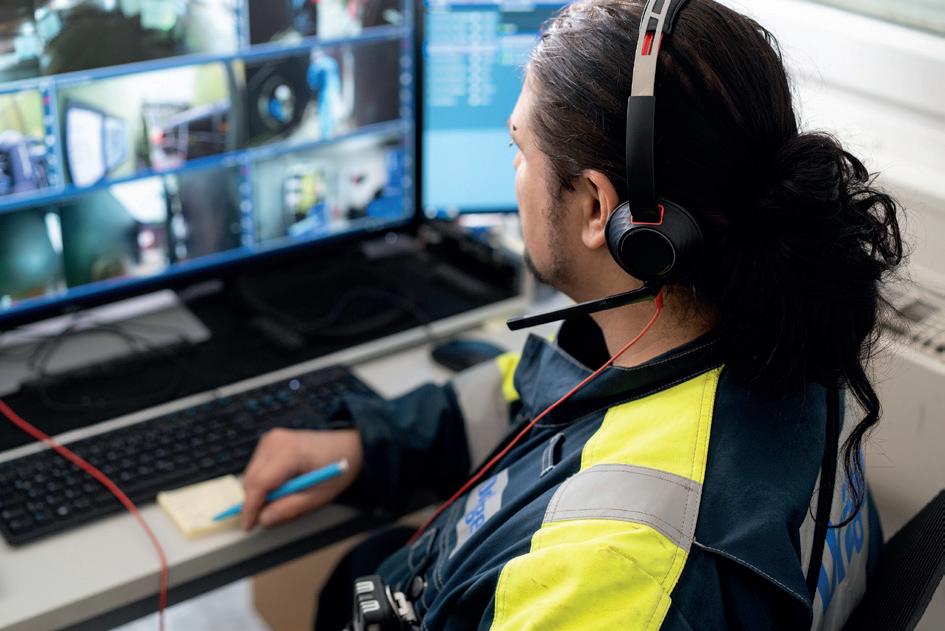
Figure 4. Eyes on system and control on safety.
José Miguel González, Tecam, looks at practical approaches to achieving emissions compliance and operational efficiency.
Storage terminals play a critical role in the global energy and chemicals supply chain, acting as key nodes between production, transportation, and end use. As regulatory frameworks evolve and environmental scrutiny intensifies, terminal operators are facing increasing pressure to reduce atmospheric emissions while maintaining operational efficiency and cost competitiveness.
Gaseous emissions from storage and handling operations – particularly volatile organic compounds (VOCs), hazardous air pollutants (HAPs), and odorous compounds – have become a focal point for both regulators and surrounding communities. At the same time, the transition towards alternative fuels and
more complex product portfolios is introducing new technical challenges in emissions management.
In this context, the role of specialised engineering partners with proven experience in emission abatement technologies is becoming increasingly relevant. Their ability to translate regulatory requirements into reliable, tailored solutions is often a key factor in achieving both compliance and operational performance.
This article explores the main emission sources in storage terminals, the regulatory and operational drivers shaping the industry, and practical approaches to achieving compliance through effective abatement technologies and system integration.
Understanding emission sources in storage terminals
Emissions in tank terminals originate from a variety of interconnected activities. Storage tanks, for example, generate vapour releases due to temperature fluctuations –commonly referred to as breathing losses – as well as during filling and emptying operations – known as working losses. These emissions are particularly relevant when dealing with light hydrocarbons and other volatile substances.
Loading and unloading operations also contribute significantly, as vapours are displaced during the transfer of liquids to trucks, railcars, or marine vessels. In addition, product handling systems – including pumps, valves, and flanges – can generate fugitive emissions, especially in facilities with ageing infrastructure or insufficient maintenance practices.
Other sources, such as wastewater treatment units, may release hydrocarbons and odorous compounds, while maintenance activities like tank cleaning and degassing often result in intermittent but high-intensity emission peaks. Addressing this diversity of sources requires appropriate technologies and a deep understanding of how these emission points interact within the overall facility.
Regulatory landscape and industry pressure
Environmental regulations governing storage terminals have become progressively more stringent in recent years. In regions such as Europe and North America, frameworks like the Industrial Emissions Directive (IED) and the associated Best Available Techniques (BAT) conclusions have established clear expectations regarding emission limits, monitoring, and operational practices.
However, regulatory compliance is only one of several drivers influencing terminal operators. Many companies are aligning their operations with broader sustainability strategies, including decarbonisation targets and environmental, social, and governance (ESG) commitments. At the same time, community expectations – particularly in relation to odour control – are becoming increasingly relevant, especially for terminals located near urban or industrial clusters.
These combined pressures are leading operators to seek not only compliant solutions, but also robust and future-proof systems that can adapt to evolving requirements. In this scenario, experience across multiple industries and geographies can provide valuable insight into best practices and emerging trends.
Technology options for emission control
A range of technologies are available to address emissions from storage terminals, and the most appropriate solution depends on factors such as the composition of the vapour stream, flow rates, concentration levels, and operational variability.
Vapour recovery units (VRUs) are widely used in applications where the recovery of hydrocarbons is both technically feasible and economically attractive. By capturing vapours – often through adsorption or condensation processes – these systems enable operators to reduce emissions while simultaneously recovering valuable product. Their effectiveness, however, can be influenced by fluctuations in flow rates and requires careful system design and operational control.
In cases where recovery is not viable, thermal oxidation systems offer a robust alternative. By oxidising VOCs at high temperatures, these systems achieve high destruction efficiencies and can handle a broad range of compounds. Regenerative and recuperative configurations are commonly used, each offering different balances between energy efficiency and operational complexity. Their implementation requires careful engineering to optimise energy use and ensure stable operation under varying conditions.
Catalytic oxidation presents a variation of this approach, using catalysts to lower the required operating temperature and thereby reduce energy demand. This can be advantageous in certain applications, although the sensitivity of catalysts to contaminants and the need for periodic replacement must be considered during system design and operation.
Flaring systems are often employed as safety devices or for handling intermittent, high-flow emissions, such as those generated during maintenance or emergency situations. Although reliable and capable of dealing with variable conditions, their use for continuous operation is generally limited due to environmental and community considerations.
Increasingly, terminal operators are adopting hybrid configurations that combine different technologies. By integrating recovery and destruction methods within a single system, it is possible to optimise performance across a wider range of operating conditions. Designing such systems effectively typically requires a strong engineering approach, supported by practical experience in similar applications.
The importance of system integration
While the selection of appropriate abatement technology is essential, the overall effectiveness of an emission control strategy depends heavily on system integration. Efficient vapour collection is a fundamental prerequisite, as even the most advanced treatment system cannot perform effectively if emissions are not properly captured at the source.
Figure 1. Operators in a tank farm.
API’s Process Safety Site Assessment Program (PSSAP®) demonstrates a commitment to a culture of safety and continuous improvement at refining, petrochemical and chemical sites.
PSSAP’S PRODUCT STORAGE AND TRANSFER ASSESSMENT WAS DEVELOPED BY INDUSTRY FOR TERMINAL SITES TO HELP EVALUATE AND IMPROVE OPERATIONAL AND MECHANICAL INTEGRITY AREAS THAT AFFECT PROCESS SAFETY AT STORAGE OR TRANSFER FACILITIES.
Managing fluctuations in flow rates and concentrations requires well-designed buffering and flow control mechanisms. Automation and advanced control systems enable real-time adjustments that maintain optimal operating conditions and minimise energy consumption.
Monitoring systems are equally important, providing the data necessary to demonstrate compliance and support continuous improvement. In practice, achieving this level of integration often involves close collaboration between terminal operators and engineering specialists, particularly when retrofitting existing facilities or upgrading legacy systems.
Challenges with new fuels and products
The ongoing energy transition is introducing a growing variety of alternative fuels and chemical products into storage terminals. Biofuels, e-fuels, and other emerging energy carriers often exhibit different physical and chemical properties compared to traditional hydrocarbons, which can complicate emission control strategies.
For instance, the higher oxygen content of many biofuels can influence oxidation processes, while certain compounds may present increased risks of corrosion or instability. Differences in vapour pressure and volatility also affect emission profiles, requiring adjustments in both collection and treatment systems.
These challenges reinforce the importance of flexible and adaptable solutions, as well as the value of experience gained from working with a wide range of industrial applications and substances.
Operational considerations
Effective emission management extends beyond technology and design, encompassing day-to-day operational practices. Preventive maintenance is essential to ensure that equipment continues to operate as intended and to minimise the risk of fugitive emissions. Well-trained personnel are also critical, as they are better equipped to identify and respond to abnormal conditions.
The use of data analytics and performance monitoring can further enhance operational efficiency by enabling operators to identify trends, optimise system settings, and anticipate
maintenance needs. Over time, this contributes to more stable operation and improved environmental performance.
Digitalisation and monitoring
Advances in digital technologies are transforming the way emissions are managed in storage terminals. Real-time monitoring systems provide continuous insight into emission levels and system performance, allowing for rapid detection of deviations and more proactive decision-making.
In addition to supporting compliance, digital tools facilitate automated reporting and improve transparency with regulators and stakeholders. Predictive maintenance capabilities can also reduce downtime and extend equipment life, contributing to both environmental and economic performance.
Economic perspective
Although emission control systems require significant investment, they can also deliver tangible economic benefits. Recovering valuable hydrocarbons reduces product losses, while energy-efficient technologies help to control operating costs. Ensuring compliance also avoids potential penalties and operational disruptions, which can have a substantial financial impact.
From a lifecycle perspective, a well-designed emission control strategy should balance capital expenditure and operational costs while maintaining flexibility for future adaptations. Achieving this balance often depends on selecting the right technology and ensuring it is properly integrated into the overall facility.
Looking ahead
The storage terminal sector is undergoing a period of transformation driven by regulatory developments, evolving product portfolios, and increasing expectations around sustainability. Emission management will remain a central challenge, requiring both technological innovation and operational excellence.
Future developments are likely to include greater integration of digital solutions, increased adoption of hybrid and modular systems, and a stronger focus on energy efficiency and decarbonisation. In this evolving landscape, access to specialised expertise and proven engineering solutions will be an important differentiator.
Conclusion
Managing emissions in storage terminals has evolved from a purely regulatory requirement into a key component of sustainable and efficient operations. By combining a thorough understanding of emission sources with appropriate technology selection and effective system integration, operators can achieve compliance while enhancing overall performance.
As the industry continues to adapt to new challenges, collaboration between terminal operators and experienced engineering partners will be essential. The ability to deliver reliable, tailored emission abatement solutions – based on technical expertise and international project experience –will play a crucial role in supporting both environmental objectives and long-term operational success.
Figure 2. RTO installed at a tank farm at Rotterdam port, the Netherlands.
Brandon Melerine and James Hill, BWC Terminals, discuss how terminal infrastructure can be optimised to ensure smooth operations amid the increasing distribution of renewable fuels, with particular emphasis on the Port of Stockton, California, US.
In April 2025, BWC Terminals (BWC) reached a milestone in California’s maritime infrastructure with the completion of the first newly constructed Marine Oil Terminal Engineering and Maintenance Standards (MOTEMS)-compliant dock in nearly three decades. Located at the Port of Stockton, California, US, the new dock was purpose-built to safely and efficiently receive
and transfer renewable diesel and biodiesel, supporting the state’s evolving energy landscape while meeting the rigorous regulatory requirements.
The Stockton dock represents more than a single infrastructure investment. It reflects a broader strategy to modernise terminal operations in a state where ageing facilities,
increasing regulatory complexity, and growing demand for low-carbon fuels are converging. By designing and constructing a facility that fully complies with current MOTEMS standards, BWC has pushed forward terminal development in California.
The strategic role of renewable fuel infrastructure
California’s energy policies prioritise the reduction of greenhouse gas (GHG) emissions across transportation and industrial sectors. While electrification continues to expand, many applications – particularly heavy-duty transportation, industrial operations, and agriculture –remain dependent on liquid fuels. Renewable diesel and biodiesel play a critical role in bridging this gap, offering lower-carbon alternatives that can be deployed using existing engines and distribution systems.
BWC’s expansion at the Port of Stockton reflects a proactive response to these realities. Over the past five years, the company increased terminal capacity by more than 500%, positioning the facility to meet rising demand for renewable fuels. The completion of the MOTEMS-compliant dock in 2025 marked the culmination of a multi-year strategy to enhance operational flexibility, particularly for marine-based deliveries.
By integrating marine, rail, and truck logistics, the Stockton terminal enables renewable fuels to move efficiently from coastal ports to inland markets. This multimodal capability strengthens supply chain resilience, reduces bottlenecks, and supports consistent fuel availability throughout California and neighbouring regions.
The terminal also contributes to energy security. Marine access adds redundancy to fuel supply routes, reducing reliance on any single mode of transportation and improving reliability during periods of disruption. As California accelerates its energy transition while managing infrastructure constraints, this flexibility becomes increasingly important.
MOTEMS compliance in a modern context
MOTEMS regulations, first established in the 1990s, set comprehensive standards for the design, construction, and maintenance of marine oil terminals in California. The regulations address structural integrity, seismic resilience, spill prevention, fire protection, and safe berthing
practices, with the goal of protecting workers, communities, and the environment.
While many existing terminals have undergone retrofits to meet evolving MOTEMS requirements, constructing a new dock designed from the ground up for full compliance is uncommon. The Stockton project stands out as the first newly constructed MOTEMS-compliant facility in nearly 30 years, demonstrating how contemporary engineering and planning can integrate safety, efficiency, and environmental protection from the outset.
Beyond initial construction, MOTEMS emphasises long-term inspection and maintenance. The Stockton dock was designed to facilitate routine inspections and ongoing compliance, reducing lifecycle maintenance challenges and allowing the facility to adapt to future regulatory updates without major operational disruptions. This forward-looking approach ensures the terminal remains compliant and functional well into the future.
Engineering and design features
The Stockton dock reflects current best practices in terminal engineering. Structural systems were designed to withstand seismic activity consistent with California’s risk profile. Advanced mooring infrastructure allows the dock to safely accommodate a range of vessel sizes, while spill-prevention systems minimise environmental risk during fuel transfer operations.
Fire suppression and monitoring systems are integrated throughout the facility, providing layered protection for personnel, assets, and surrounding areas. Operational systems are designed with redundancy in mind, ensuring continuity and safety even under abnormal conditions.
Automation plays a key role in improving both safety and efficiency. Monitoring and control systems support precise fuel transfers, early detection of irregularities, and rapid response to potential issues. These capabilities increase throughput while maintaining strict adherence to safety standards, allowing the terminal to handle growing volumes of renewable fuels without compromising performance.
Environmental considerations were integral to the design process. The project underwent review according to the California Environmental Quality Act (CEQA) and received a Mitigated Negative Declaration. Potential impacts to water quality, shoreline habitats, and local wildlife were evaluated, and mitigation measures were incorporated into both construction and operational plans. These efforts ensure responsible operation within the sensitive San Joaquin River environment.
Construction strategy and workforce engagement
Construction of the dock was executed under a Project Labor Agreement with the San Joaquin Building Trades Council, utilising skilled local union labour across multiple trades. Approximately 30 construction jobs were created during the build phase, with 18 permanent terminal positions supported following commissioning.
Figure 1. MOTEMS dock at the Port of Stockton.
Workforce engagement was central to the project’s success. The use of experienced local labour contributed to high-quality execution, adherence to safety standards, and efficient project delivery. Collaboration between BWC, contractors, and labour partners ensured alignment on timelines, safety expectations, and technical requirements.
The Stockton terminal was developed using a phased expansion strategy. By incrementally adding storage capacity and infrastructure, BWC maintained operational continuity while responding to market demand. This approach allowed safety systems, environmental controls, and technological upgrades to be integrated methodically, reducing risk and minimising disruption to ongoing operations.
Economic and supply chain impact
The new dock strengthens California’s renewable fuel supply chain by providing a dedicated marine transfer point for renewable diesel and biodiesel. Marine deliveries complement existing rail and truck capabilities, enabling flexible routing and efficient distribution throughout the state.
Improved throughput and reliability support downstream customers while contributing to broader supply chain stability. The terminal’s expanded capabilities also enhance the Port of Stockton’s role as a key inland distribution hub, reinforcing its importance within California’s energy logistics network.
From an economic perspective, the project generated meaningful local benefits. Construction activity supported regional employment, while ongoing operations provide stable, long-term jobs. The terminal also supports a network of local service providers, including transportation, maintenance, and logistics firms, amplifying its economic impact within the community.
Environmental stewardship and sustainability
Environmental stewardship guided every phase of the Stockton project. Spill prevention, containment systems, and fire protection infrastructure were designed to safeguard the San Joaquin River and surrounding ecosystems. Operational procedures prioritise safe handling and transfer of renewable fuels, minimising environmental risk.
By facilitating the movement of renewable diesel and biodiesel, the terminal directly supports California’s low-carbon fuel objectives. These fuels offer significantly lower lifecycle GHG emissions compared to conventional diesel, and efficient distribution infrastructure is essential to maximising their impact.
The Stockton dock enables higher volumes of renewable fuels to reach end users reliably, contributing to emissions reductions across transportation and industrial sectors. In this way, infrastructure investment becomes a critical enabler of the state’s broader sustainability goals.
Community impact
Community engagement was an important component of the project’s development. BWC worked with local
organisations and educational institutions to support workforce development and career pathways within the maritime and industrial sectors. Training initiatives and employment opportunities helped build a skilled local workforce aligned with the region’s economic needs.
The project also supported community resilience by creating jobs, engaging local suppliers, and reinforcing the Port of Stockton’s role as a regional economic driver. Through sustained engagement, BWC ensured that the benefits of the terminal’s expansion extended beyond operational improvements to tangible social and economic outcomes for the surrounding community.
Stakeholder collaboration
The successful delivery of the Stockton dock relied on close coordination among multiple stakeholders, including the Port of Stockton, regulatory agencies, government officials, and labour partners. Early and consistent collaboration ensured alignment on regulatory requirements, environmental considerations, and operational objectives.
This collaborative approach demonstrates how public-private partnerships can advance complex infrastructure projects while balancing safety, compliance, and community interests. The Stockton project provides a model for future terminal developments in highly regulated environments.
Lessons learned and industry implications
Developing a new MOTEMS-compliant dock from the ground up offered valuable insights for the terminal industry. Early regulatory engagement proved essential in navigating permitting and environmental review processes. Integrating safety, maintenance, and compliance considerations into initial design decisions reduced long-term risk and improved operational flexibility.
For the broader industry, the Stockton dock establishes a clear benchmark for modern terminal construction in California. It demonstrates that new infrastructure can meet stringent regulatory requirements while supporting renewable energy goals and economic development.
Looking forward
The completion of the Stockton MOTEMS-compliant dock marks a key moment for BWC Terminals and for California’s terminal sector. The facility enhances renewable fuel distribution capacity, strengthens supply chain reliability, supports local economic growth, and advances environmental performance.
As the first newly constructed MOTEMS-compliant dock in nearly 30 years, completed in 2025, the project illustrates how modern infrastructure can be designed to meet both present and future energy challenges. Through strategic investment, thoughtful design, and collaboration, BWC has demonstrated that terminal modernisation can play a meaningful role in California’s clean energy transition.
Gard Reian, Jotun AS, considers the challenge that storing biofuel feedstocks presents for modern tank lining technologies.
One of the UN’s sustainable development goals is affordable and clean energy. Under this umbrella, biofuels are getting more attention. Most of today’s fuel is still derived from crude oil, but the industry is witnessing a gradual shift towards fuel developed from more sustainable sources, like used cooking oil or various by-products from palm oil production. What is the challenge? While crude oil and its derivatives are generally less aggressive toward modern tank lining technologies, biofuel feedstocks present a different challenge. They often contain high amounts of free fatty acids (FFAs) and water, and they are stored at high temperatures to keep them liquid and pumpable.
In a recent study, Jotun examined how different types of fatty acids, water levels, and temperatures affected the performance of some common, commercially available, tank linings. The work tested four different linings – three epoxy systems and one glass-flake reinforced vinyl ester system –against a range of pure fatty acids chosen to push these materials to their limits. What emerged was a clear picture of how molecular size (length of fatty acids), water content, and temperature all affect lining performance and durability.
Small molecules, big trouble
One of the most striking findings of this study was just how influential the size of the fatty acid is when it comes to aggressiveness. The smaller the acid, the quicker the lining took damage. Of all the acids tested, the smallest (C8 chain length
fatty acid) was consistently more aggressive. The lower molecular size allowed the smaller acids to more easily penetrate the lining. In addition to this, the smaller acids also have a lower pKa than the larger ones (pKa is a measure of how strong an acid is – the lower the pKa value, the stronger the acid). Based on this, one could logically assume that something like coconut fatty acid –which has a high content of the C8 - C12 acids – would be more aggressive towards a lining than a palm derived fatty acid –which has more of the C16 - C18 fatty acids.
Epoxy vs vinyl ester
Linings based on epoxy are often the first choice when one is looking for chemical resistance as they are easy to apply and have a broad chemical resistance. But in FFA-rich conditions, their limitations become evident. Across the board, the epoxy linings tested degraded quickly, especially when exposed to the smallest fatty acids at elevated temperatures. The solvent-borne novolac epoxy lining performed better than both the solvent free novolac lining and the solvent borne bisphenol A epoxy based lining, but none survived long-term testing.
In contrast, the glass flake reinforced vinyl ester lining offered stronger performance. It was the only coating that passed 180 days immersion in most of the tests and even after exposure it maintained good adhesion and strong barrier properties (tested using electrical impedance spectroscopy – EIS). Full testing details – along with complete data tables – are available in AMPP Paper No: C2025-00022.1
Vinyl ester likely performs better than epoxy due to a combination of several factors: inherent properties of the binder itself, glass flakes providing a barrier effect, and coating thickness. The vinyl ester system was applied at a significantly higher film thickness than the epoxies (1500 µm vs 300 - 400 µm).
Temperature: an accelerating factor
Heat is an unavoidable feature in biofuel precursor storage, especially for high fatty acid containing vegetable oils, or vegetable oils with a naturally large-sized fatty acid composition. Some biofuel precursors are solid at room temperature and need to be kept heated to ensure they remain in liquid form.
From this testing it was seen that even a relatively small increase from 70°C to 80°C greatly accelerated the failures observed. This held true for all coatings and all fatty acids tested.
For operators, this underscores the value of keeping the temperature as low as feasible. In a real-life scenario, the temperature will often be higher at the tank bottom, beneath the heating coils, and it is logical to assume that lining failures would occur faster in these areas than in cooler parts of the tank. Because temperature has such a strong influence on coating integrity, reducing the temperature at the coating surface is critical for mitigating the risk of failure. Although the design service temperature in the tank is typically below 80 °C, localised hot spots can occur and may accelerate coating degradation, eventually leading to failure. These hot spots most commonly develop in the vicinity of heating coils. Through appropriate tank design and operational measures, both the maximum temperature and the extent of areas exposed to hot spots can be reduced. It is therefore essential that tank design, operational practices, and coating material selection are aligned to define and maintain a safe operating window.
Water makes a harsh environment even harsher
While the FFAs themselves are the main ‘bad guys’ in this story, water proved to be an equally important factor. Although the mechanism is not fully understood, it is believed that higher water content leads to a higher concentration of damaging acid species (the so-called hydronium ions, H3O+). These are small molecules and can easily penetrate the lining, likely much more easily than the
FFAs themselves. When 10% water was added to the FFAs tested, even the vinyl ester lining – which performed without any challenges at 1% water level – began to struggle, and blister formation was seen. For the epoxy linings tested, 10% water level was deemed too aggressive to even consider testing, and so these were tested only with 1% water added.
Controlling moisture content – whether through feedstock treatment or tank design – could be one way of extending the lifetime of a tank lining.
What does this mean for the biofuel industry?
As biofuel production becomes more common, it is important to understand the chemical behaviour of the varying biofuel feedstock, both for process stability and for the long-term integrity of the storage tanks.
This study highlights several important points for operators:
n Feedstock knowledge: small FFAs are rare in most natural oils but can appear in certain waste-derived streams. Even small amounts can significantly influence a lining’s durability.
n Moisture control: the more water, the quicker degradation happens. Minimising water content will prolong the lifetime of the lining.
n Temperature control: reducing overall temperatures and the occurrence of hot spots will extend the durability of the lining.
n Coating selection is key: for the most aggressive conditions (small FFA, high water content, high temperatures), epoxies –even novolac type – might not be suitable in the long run, depending on the specific conditions. Under these conditions, a glass flake reinforced vinyl ester offers significantly more robustness.
It should be noted here that the laboratory exposure conditions chosen in this study were intentionally chosen to be more severe than any possible real-life scenario, to better differentiate between different lining technologies. There are many real-life scenarios with biofuel feedstock where an epoxy would perform very well.
Looking ahead
The move toward renewable fuel sources is changing the performance demand placed on protective linings, especially for epoxy-based linings. As the world moves away from crude oil towards renewable fuel feedstock, the industry must be able to adapt. And a part of this adaption is to understand how traditional linings behave in these new environments, and how to choose the correct lining.
Although the conditions tested were harsher than most real-life conditions, this study highlights the importance of evaluating lining performance in conditions that simulate worst-case scenarios: high moisture levels, elevated temperatures, and small FFA compositions. It also reinforces the need of cooperation: coating suppliers and asset owners need to work together as feedstock continues to change and evolve.
One thing is clear: with the right binder technology, and a solid understanding of the chemistry involved in failure, biofuel storage infrastructure can be made both durable and future ready.
Reference
1. AMPP Paper no.: C2025-00022.
Figure 1. Panels of glass-flake reinforced vinyl ester lining. From left to right: C8 fatty acid, C10 fatty acid, and C12 fatty acid. All tested at 70°C with 1% water added, by weight.
Maintain steel integrity ®
Motivated by the toughest of conditions, we constantly seek to solve the problems that lie ahead. As a trusted maintenance partner, we offer innovative products and technologies that deliver exceptional performance for steel assets.
Support efficient operations
Reduce hazards and risk Minimise environmental impact
A podcast series for professionals in the downstream refining, petrochemical, and gas processing industries
LISTEN NOW
SAF: ready to take flight
Maurits van Tol, CEO of Catalyst Technologies, Johnson Matthey, explores the role of sustainable aviation fuel (SAF) in reducing emissions, and outlines the most promising pathways and innovations in the sector.
Natural gas: an unexpected bridge fuel
Simon Lack, Managing Partner at SL Advisors LLC and Co-Portfolio Manager of the Catalyst Energy Infrastructure Fund (MLXIX), talks us through natural gas’ emerging role as a bridge fuel that is powering two fast-growing industries: AI-driven data centres and US LNG exports.
Has the turning point for CCS arrived?
Pedram Fainaloo, Director of the Low Carbon & CCS Segment –North America, Energy Systems at DNV, considers if the turning point for carbon capture and storage (CCS) has arrived and outlines some of the most viable CCS opportunities in downstream operations.
How to specify optimal coatings to combat an array of corrosion challenges
John Zimmerman, Key Account Manager for Sherwin-Williams Protective & Marine, covers an array of common corrosion challenges energy producers
Sponsored by
Listen and subscribe here
John Zimmerman, Calvin Sumner, and Rob Galvin, Sherwin‑Williams
Protective & Marine, consider how strategic lining overcoats can help to extend storage tank performance and achieve significant savings.
Today’s high-solids, high-performance tank linings are engineered to deliver dependable protection for 30 years or more. However, no coating lasts forever. When deterioration inevitably surfaces, many owners automatically plan to perform a full lining removal and replacement. Yet in numerous cases, a more economical, less disruptive option is available: overcoating the lining. Carried out under the right conditions, an overcoat can add years of tank service at a fraction of the cost and downtime of a complete reline.
The reflex to perform full lining restorations comes from experience and standards that prioritise risk reduction. However, based on collective field data, many tank linings are still structurally sound at the middle to end of their anticipated service life. In these cases, an overcoat can deliver budget flexibility by deferring major capital expenditures and compressing downtime windows. Most importantly, this can be done without compromising performance when the proper evaluation and controls are in place.
The critical criteria required to make an assessment on whether a lining overcoat is possible include the condition of the tank itself, the history of the contents stored inside since the lining was installed, the condition of the existing lining, and other factors. When these variables align with a positive assessment from certified inspectors – perhaps along with help from a coatings
Figure 1. A lining may be considered for overcoating if minimal bottom side corrosion and pitting are present, with no compromise of the tank’s structural integrity.
manufacturer – overcoating may be a prudent choice. Working closely with those parties can help tank owners determine whether the cost, schedule, and risk profile favour an overcoat or a total lining replacement.
The economy of overcoating
Every tank interior takes some abuse. Corrosive cargoes, cyclic temperatures, mechanical impacts, and routine operations can all take a toll on linings over time. When that use results in delamination of the lining, widespread mechanical damage, or clear evidence of underfilm corrosion, many owners will elect to perform a full removal and reline. In tanks in which ultrasonic testing shows bottomside steel loss or in which numerous patch plates are already in place, that instinct is usually correct (Figure 1). The only defensible path may be a comprehensive reline.
Despite full lining replacements being the norm, significant evidence is available to reinforce the viability of overcoating linings when conditions permit. Owners, inspectors, and coating suppliers have observed many overcoated systems performing well when the original lining still exhibits good adhesion and overall integrity (Figure 2). Given that tanks featuring modern 100% solids linings often arrive at midlife in better shape than similar assets did a generation ago, the risk profile for an overcoat has been lowered and the value proposition has improved.
In fact, owners who choose to overcoat when feasible can realise advantages such as:
n Shorter outages: overcoating typically returns an asset to service faster than a full blast and reline, reducing production costs and scheduling pain.
n Lower labour demand: because the existing liner stays in place, surface preparation is lighter, and the overcoat usually requires fewer mils of build, trimming both labour hours and complexity.
n Reduced total spend: less blasting, lower coating volumes, and smaller waste streams decrease the overall project expense.
Figure 2. Collaborating with technical representatives from coatings manufacturers can help tank owners evaluate the feasibility of overcoating a lining with limited delamination and modest mechanical damage.
n Budget balancing: by extending service through another inspection interval, an overcoat can push the larger capital hit of a complete reline into the future, freeing near-term dollars for other priority work.
When to reconsider overcoating
Deciding whether a lining is a viable overcoat candidate is a screening exercise. Paper qualifications, including product histories, repair logs, and prior inspection data, come first, followed by a hands-on interior assessment to validate the findings.
Several scenarios commonly tilt the final assessment decision away from overcoating and toward full removal, including the following:
The tank held aggressive or water sensitive cargoes in the past
Products with a very high or low pH, certain fertilizers and chemicals, or cargoes prone to
water sensitivity can infiltrate a coating matrix and linger. Even rigorous cleaning and mechanical preparation may not eliminate contaminants embedded in the lining, which can interfere with adhesion or shorten the life of any overcoat.
The tank has an unknown service history
Overcoating is a higher risk choice when the tank’s commodity storage history is unknown. This is particularly true for swing service assets where records may be incomplete. Lack of certainty about past exposures raises the potential for hidden incompatibilities.
The linings are aged and brittle
As some systems age, they lose flexibility. During surface preparation, those brittle films can fracture, creating new defects that undermine the bond of the original lining and therefore the overcoat, accelerating the potential for failure.
There are film-build constraints
Each lining system has a maximum recommended dry film thickness (DFT). If adding an overcoat would push the total beyond that limit, the resulting internal stress from cure shrinkage, thermal cycling, and operational strains can reduce flexibility and shorten service life.
The tank has questionable mechanical integrity
After decades in service, tanks may carry the accumulated effects of corrosion, patch plate repairs,
and fatigue from pressure and thermal cycling. If any steel loss is significant – or if the patch plate count exceeds an owner’s internal threshold – adding more coating weight and stiffness may not be prudent. Here, judgement and owner criteria vary, but caution usually prevails.
These screening factors do not automatically rule out an overcoat. Instead, they frame the risk. The final call rests on inspection data and, ideally, the input of experienced technical service representatives.
Testing for overcoating eligibility
Before selecting an overcoat strategy, tank owners must perform a thorough, fit-for-purpose evaluation. Some owners may rely on visual examination alone to flag delamination, blistering, and impact damage. Most, however, will layer in targeted testing aligned with API Recommended Practice 652 and API Standard 653, using pass/fail criteria developed with a coatings supplier to ensure the evaluation is both rigorous and relevant to the asset.
Typical investigative tools include:
n ASTM D6677-18, Standard Test Method for Evaluating Adhesion by Knife: a cross cut/knife method is used to gauge the bond strength of the existing film.
n ASTM D4541-22, Standard Test Method for Pull-Off Strength of Coatings Using Portable Adhesion Testers: a hydraulic adhesion test allows inspectors to quantify pull-off values at representative locations throughout the tank.
n ASTM D714-02, Standard Test Method for Evaluating Degree of Blistering of Paints: a visual rating system is used to compare blister sizes and densities to photographic standards.
n ASTM D2240-15, Standard Test Method for Rubber Property – Durometer Hardness: inspectors will determine the Shore D hardness of the lining and whether it is too brittle to handle an overcoat.
The knife and pull off adhesion methods are typically destructive at the test spot and require subsequent touchups. That is acceptable in the context of a maintenance project in which either an overcoat or a complete reline will follow. The goal is to secure clear evidence. If the adhesion, blistering, and hardness values are in the right range, the confidence in an overcoat rises.
Inside the overcoating process
Once a tank clears the eligibility checks, the maintenance team can craft an overcoat plan. This is less about designing a brand-new lining system and more about ensuring compatibility and adhesion between the existing film and the new application –without exceeding total film build limits. Coatings manufacturers can be valuable partners in optimising the product selection, preparation, and application parameters for the specific tank and service.
Figure 3. Using ultra high solids systems, such as Dura Plate® UHS or Nova Plate® UHS, permits efficient lining overcoating, with the material often able to be installed in a single coat.
The 2026 API Storage Tank Conference will give attendees an opportunity to learn about new and existing industry codes and standards, including industry best practices, and provide an opportunity to hear about emerging trends from industry experts. This conference offers over 25 sessions addressing the needs of individuals involved in production systems, pipelines, terminals,
and storage facilities. Each day focuses on presentations relevant
Surface preparation
Adhesion starts with cleanliness. High-pressure water washing removes residual salts and general contaminants. If the tank previously stored hydrocarbons, technicians can use detergents or alkaline cleaners to help break down oily films and organic residues that ordinary washing may not remove. Getting this step right reduces the risk of blistering and adhesion loss later.
After cleaning, mechanical preparation typically involves spot and sweep blasting per SSPC SP 18, Near-White Metal Blast Cleaning. The objective is to roughen the existing film for mechanical adhesion while preserving as much sound lining as possible. Coatings experts can advise on the appropriate blast media and pressures to achieve the desired profile without shredding the coating underneath.
Product selection and application
The overcoat must be compatible with the existing lining system and the tank’s intended service commodities. Common solutions include ultra-high-solids epoxy amines, such as Dura-Plate® UHS, and novolac epoxies, such as Nova-Plate® UHS or Nova-Plate® 360. These coatings meet chemical-resistance and temperature needs while keeping the overcoated lining within total DFT limits. Ultra-high-solids technologies often reach the specified thickness in a single coat, accelerating schedules and reducing labour exposure (Figure 3).
Flexibility matters. The steel shell, the existing lining, and the new overcoat each expand and contract at their own rates. Choosing an overcoat with suitable flexibility helps the composite system absorb those movements without cracking or losing adhesion. Where the steel substrate is exposed (from testing or localised repairs), a compatible primer may be used, but broad
priming is typically unnecessary in a true overcoat scenario.
Inspection and quality control
Quality assurance should not be a final step. It runs from surface preparation through final cure (Figure 4). It is helpful to work with AMPP Coating Inspectors throughout a project, as these trained professionals can confirm the surface profile and cleanliness of the prepared areas prior to coatings, document pre and post-application DFT readings, and perform holiday detection using low voltage ‘wet sponge’ methods to identify discontinuities that could allow underfilm corrosion. Areas that fall below target thickness or show holidays will need to be repaired and reinspected before the tank is returned to service.
A disciplined quality assurance/quality control regimen does not add bureaucracy. It preserves the return on investment (ROI) of the overcoat by ensuring the work can actually deliver the expected life extension.
Reaping the rewards
An overcoat is not a shortcut around the proper assessment of a lining for continued service. It is also not a cure all for deeply compromised tanks. When the existing lining film is poorly adhered, severely embrittled, or already over thickness, the responsible recommendation would be to remove and replace it. Likewise, if the lining’s mechanical integrity is suspect, coating decisions must follow structural remediation, not precede it.
Conversely, when the lining’s adhesion is strong, blistering is minimal and well understood, hardness and flexibility are within tolerances, and the total film build following overcoating will remain within specification, an overcoat is possible. Based on those assessments, tank owners and supportive partners can consider this measured, risk-aware way to capture additional service life now, while postponing a major capital project without sacrificing reliability. The cost savings could be significant – but only if all parties have followed discipline in screening the tank for overcoating eligibility and if the overcoat lining is properly applied and inspected.
No owner should have to make this call alone.
AMPP Coating Inspectors from coatings manufacturers routinely assist with tank assessments, test selection, and criteria development. They can help owners weigh overcoat feasibility against the demands of the product to be stored, the condition of the substrate, and the performance history of the existing film. Equally, they will recommend full removal and replacement when indicators warrant it. That impartial guidance is essential to minimising risk.
When findings support an overcoat, the upside can be substantial. Tank owners can realise lower costs today, reduced downtime, and an extended interval before the next major lining project. They should also have high confidence in the tank delivering safe, compliant service.
Figure 4. Prior to putting a tank back in service following a lining overcoat, inspectors will verify the film build and perform holiday testing to confirm continuous protection.
Figure 1. In the controlled shop environment, applicators spray the coating system onto steel plates, ensuring uniform coverage and optimal film build before transport.
Tony Collins, Eoncoat, USA, presents a case study of a tank bottom project where corrosion protection meets environmental responsibility.
The soil-facing side of bottom plates has long been a hidden vulnerability. Moisture, soil electrolytes, chlorides, and microbial activity create aggressive external corrosion conditions that are nearly impossible to inspect or repair without taking the tank out of service. For utilities managing ageing infrastructure, the result is often premature thinning, leaks, or multimillion-dollar bottom replacements.
This article will explore a recent storage tank project in Bedford, Texas, US, where the Trinity River Authority of Texas (TRA) specified a specialised chemically bonded phosphate
ceramic (CBPC) coating system, which was applied to the soil-facing side of the plates. The focus of this project was uncompromising corrosion protection paired with genuine environmental stewardship. As such, the selected coating does not contain volatile organic compounds (VOCs), hazardous air pollutants (HAPs), or toxins, delivering a 100% solids, high-performance barrier that protects both the asset and the surrounding environment.
While the project outlined in this article is for the water storage tank industry, the applicability and learnings can be equally applied to the oil and gas tank storage sector.
The challenge and the solution
Even well-designed foundations cannot fully eliminate moisture migration to the underside of tank bottoms. Traditional approaches – relying solely on cathodic protection or generic shop primers – often fall short over decades of service. TRA opted to build protection in from day one with a dedicated soil-side coating engineered for long-term immersion and soil contact.
A key reason for selecting EonCoat’s chemically bonded phosphate ceramic technology is its ability to withstand the intense heat and stresses of welding. Polymer-based coatings typically burn off or degrade during the lap and butt welding required to join bottom plates in the field, creating unprotected zones vulnerable to immediate corrosion. In contrast, the CBPC formulation selected for this project has no carbon atoms in its structure – it is inorganic and cannot burn or combust under welding temperatures (rated up to 1202°F/650°C for weldable variants). This ensures continuous, uninterrupted protection before, during, and after welding, eliminating voids and maintaining full corrosion resistance across the entire bottom.
This technology was developed at the request of Honeywell in 2018, specifically to address the need for a weldable, permanent corrosion barrier in demanding industrial applications like storage tank bottoms. The result is a coating that alloys directly with the steel surface, forming an inert iron phosphate layer topped by a hard phosphate ceramic –providing dual-layer, self-healing protection that is long-lasting. In 2023, Chevron and Charter Labs presented the results of their extensive testing of the technology at AMPP, concluding that the coating survives the weld process and will protect the steel for many years.
The system delivers excellent adhesion and barrier properties after blasting to a 125 µm surface profile; resistance to pitting, crevice corrosion, and microbiologically influenced corrosion; full integrity through welding without burn-off or damage; extended service life; and complete elimination of VOC, HAP, and toxic emissions during application and in service.
Project execution
Over the past eight years, EonCoat tank bottom coatings have primarily been applied in the field during tank construction or rehabilitation. The Bedford project was the first job where the bottom plates were coated in a controlled shop environment (Figure 1), then shipped to the site fully protected.
The plates arrived pre-coated on the soil-facing side, oriented face-down for transport and handling. This approach simplified installation (Figure 2) – the tank crew simply dragged each plate into position inside the tank shell and welded it in place, with no additional surface preparation or coating required on the protected underside. The coating’s weldability ensured zero degradation during welding, preserving full protection integrity from fabrication through final erection.
For future projects, plates will be shipped pre-cut to exact drawing dimensions, further streamlining on-site assembly and reducing labour, time, and potential variables.
The surface was grit blasted to 125 µm and the coating was applied in the shop under controlled conditions. Archer Weston coordinated the details of the project, from coating application through the careful transport and installation of the pre-coated plates.
Importance to the tank industry
TRA’s Bedford project demonstrates that corrosion protection and environmental responsibility are not mutually exclusive. By choosing a carbon-free, weldable CBPC coating free of VOCs and HAPs, the utility extended the life of a critical water storage asset and aligned with growing industry and regulatory emphasis on sustainable, efficient practices.
The rugged ceramic coating, which will not burn when welded, made it easy for the crew to use mobile equipment to drag the plates into the tank (see Figure 3). TRA benefits from a system that speeds up the job, and a tank bottom that should last as long the tank.
With experienced contractors like Archer Weston, the approach becomes repeatable and scalable – with shop pre-coating and pre-cut plates paving the way for even greater future efficiencies.
Note
The project, and this article, were made possible by the help of Steele Foxhall, Chris Martin, and Mohammad Bayan, PE.
Figure 2. Workers guide a large pre-coated bottom plate during crane installation into the tank shell, showcasing precise field coordination and the clean, protected underside.
Figure 3. A Bobcat T770 carefully drives across the pre-coated bottom plates at the Bedford site, demonstrating the coating’s immediate durability and toughness during heavy-equipment handling (February 2026).
Julie Holmquist, Cortec® Corp., and Shane Baker, Cortec Global Services (CGS), discuss the benefits of vapour corrosion inhibitor (VCI) technology for tank bottom and cased pipeline corrosion mitigation.
The last two and a half decades have seen a shift in the oil and gas industry’s approach to corrosion protection on aboveground storage tank (AST) bottoms and inside cased pipeline crossings. The use of vapour corrosion inhibitors (VCIs) has emerged as a supplement to the primary strategy of cathodic protection (CP). While VCIs became popular in the mid-1900s for preservation of wartime assets, it was not until the late 1990s 1 and early 2000s 2 that they
started to be seriously used and tested as a method of AST bottom protection from soil-side corrosion. As data accumulated over time, it became evident that VCIs were a viable alternative and complement to CP. Their practical acceptance by industry users is reflected by the adoption of VCIs in standards such as API Technical Report 655 3 in 2021 and AMPP SP21474-2023 4 in 2023. While testing and data collection continue, another important step in VCI standardisation is achieving broader
awareness of the benefits of VCI technology among those who manage oil and gas storage facilities. By understanding how VCI works and where it has been used, decision makers can better evaluate the advantages of adopting VCI and whether it warrants a shift in their corrosion prevention strategy.
The affinity of VCIs for metal void space protection
VCIs come in many forms, including salts of amine carboxylates. These salts, whether applied as a powder or mixed with water, have varying degrees of volatility that allow them to diffuse as vapours through the air. When trapped within a void space, their affinity to metal allows VCI molecules to adsorb onto metal surfaces, creating an invisible protective layer that blocks the interaction of metal molecules with oxygen and moisture, slowing down or completely avoiding the formation of a corrosion cell. As long as the VCI molecules remain inside the void space, they continue protecting the metal surfaces.
This vapour-phase protective action makes VCIs very adaptable to enclosed spaces of many shapes and sizes. Beneath AST bottoms, VCIs are able to diffuse through sand and form a protective molecular layer on metal surfaces where the uneven tank bottom is not in direct contact with the cathodically protected sand pad. Inside casings designed to provide extra protection from physical impact on piping passing under roads or berms, VCIs offer supplementary corrosion inhibition by diffusing through difficult-to-reach areas where no protection has been applied, where CP has shorted, or where coatings or wax fillers may have failed.
CP/VCI installation and maintenance comparisons
Representative challenges for CP installation include oversized tanks and double bottoms. Some tanks cover 1 acre (0.4 ha.) of land, making it easy to lose the drill head signal under the tank by the time it gets halfway across. It may not be possible to regain reception until the drill head nearly reaches the other side, making directional drilling for CP installation highly impractical on extra-large tanks. Double bottom tanks also create more complications for CP. A second bottom is often installed when corrosion in the original tank floor becomes severe enough to threaten tank integrity. Before adding the second bottom, several inches of clean sand may be placed over the first bottom, along with a CP system. In some instances, it is necessary to install a lattice-work of metal strips across the tank bottom and spot weld every corner before a new bottom is installed. The final step is to then hook it to a rectifier. In contrast, adding VCI to a double bottom tank involves drilling holes through the tank wall into the space between the two floors, injecting VCI slurry, and installing electrical resistance (ER) probes. Furthermore, while CP grid systems can only be installed at the same time as the new tank floor, VCI can be added to double bottom tanks even after they have been put into service.
While VCI and CP systems both require workers to take monthly corrosion readings, CP can become more complicated if the voltage is out of bounds and/or corrosion is detected. This may require adjustment of the rectifier or replacement of the anodes. In contrast, VCI is relatively maintenance-free.
Figure 1. Single bottom tank at US East Coast tank farm received VCI injection through ports drilled in the concrete ring wall (image courtesy of Shane Baker).
Figure 2. ER probe placed after VCI injection to continue monitoring corrosion potential readings under the tank (image courtesy of Shane Baker).
The relative ease of VCI application and maintenance does not mean that CP is out of the picture. In some cases, VCI is combined with CP to boost overall protection. In other cases, only one method is used. Sometimes, VCI is not added until the CP system needs a retrofit since VCI application is less invasive.
Case studies
US East Coast tank farm
A tank farm on the US East Coast stores a variety of petroleum products not far from the Atlantic Ocean. In this highly corrosive environment, tank operators pay close attention to rectifier readings and take steps for remediation when corrosion potential readings on CP systems fail to meet standards. For several consecutive years, the client identified four to 12 priority tanks where they wanted their contractor to carry out CP or VCI remediation work. Many were single bottom tanks where VCI protection was needed as a supplement to deficient CP activity. The crew would drill holes in the ring wall and inject VCI at a dozen different points on average (depending on tank size). When finished, they would insert ER probes at VCI injection points for easy monthly monitoring of corrosion potential by technicians.
VCI at southern US oil terminals
A crude oil transport company asked for similar VCI application work underneath several massive tanks (277 ft [84 m] dia.) in Texas, US. The tanks were already under construction, so the team had a narrow timeframe – from 16.30 pm on Friday night to 07.00 am Monday morning – to complete VCI application before welders returned for a new week of work. Fortunately, this situation allowed the team to apply VCI via injection through the empty tank floor. The tank floor was mapped out and the team identified where to drill holes to evenly inject and distribute VCI beneath the floor. Workers circled each drill site in red for easy visibility in the dark tank environment, then plugged each hole and painted a red ‘X’ on the panel when VCI injection was complete. With the tank covering 1 acre (0.4 ha.) of land, it took two days to drill holes and inject VCI (much time was devoted to mixing VCI powder with water, which is no longer necessary with the availability of a ready-to-use slurry form). When the weekly shift started, tank builders welded a small patch over each injection point to finish the job. The same client used VCI to protect tanks at the Cushing tank terminal in Oklahoma, US. Data collected at this tank terminal from 2014 to 2019 offered helpful insights on VCI/CP benefits and interaction, indicating that the use of VCIs in conjunction with CP for five years had significantly decreased corrosion rates compared with the previous three years of CP-only protection.5 Repeated application requests by the same company in two locations underscores their high rate of satisfaction with VCIs.
VCI for cased piping systems
Another US East Coast storage facility requested VCI protection of onsite terminal pipelines feeding in and
Figure 3. Drilling VCI injection ports for double-bottom tank. Two parallel horizontal lines show the locations of the original floor (lower line) and the newest floor (top line) (image courtesy of Shane Baker).
Figure 4. Injection through the tank floor is one of the easiest ways to apply VCI; although other options exist for application on new, existing, and in-service tanks (image courtesy of Shane Baker).
out of ASTs. Similar to larger transport pipelines, these piping systems were enclosed in larger casings for physical protection under tank farm berms or roads. Corrosion protection was needed within the casing voids, so the team injected what they calculated to be enough VCI for 40 ft (12 m), sealing and wrapping the ends of the casings to keep VCI inside and corrosive elements out. The client expressed initial satisfaction with the quick and clean application process and more positive feedback was received after the inspector reported good corrosion potential readings in the following months.
Time for a shift in corrosion potential?
Industry standards are often a good reflection of what has already been accepted as a standard industry
practice. However, it is also helpful to hear specific examples of where CP/VCI application has been observed on tanks across the US. As evidenced in this article, oil and gas industry players can shift their corrosion prevention potential by adopting VCIs as a complement to traditional CP.
References
1. SHUKLA, P. K., 'Vapor Corrosion Inhibitors for Corrosion Control of Aboveground Storage Tank Bottoms', SRNL-MS-2021-00110. Pipeline Research Council International, PHMSA R&D Forum, (1 December 2021), accessed 11 March 2026, https://primis-meetings.phmsa.dot. gov/meetings/f4a3f78b-a3eb-4c51-bbda-4407d9db68e8/ files/5ac36e47-f1e2-4135-903a-8e3d21f3b33e/PRCIPavan_Shukla.pdf.
2. WHITED, T., 'Corrosion Slowed on Tank Bottoms', Pipeline & Gas Journal, accessed 11 March 2026, https://www.cortecvci. com/Publications/Papers/Petro_Chem/VpCI-608.pdf.
3. 'Volatile Corrosion Inhibitors for Storage Tanks', American Petroleum Institute, API TR 655, (28 April 2021), accessed 11 March 2026, https://www.apiwebstore.org/ standards/655.
4. 'External Corrosion Control of On-Grade Carbon Steel Storage Tank Bottoms', Association for Materials Protection and Performance (AMPP), AMPP SP21474-2023, (31 May 2023), accessed 11 March 2026, https://store.ampp. org/ampp-sp21474-2023-external-corrosion-control-of-ongrade-carbon-steel-storage-tank-bottoms.
5. WHITED, T., OLUIC, A. J., and HOLMQUIST, J., 'Reducing Soil-Side Corrosion in Aboveground Storage Tanks', Chemical Engineering , (1 January 2023), accessed 11 March 2026, https://www.chemengonline.com/reducing-soil-sidecorrosion-in-abovegound-storage-tanks/?printmode=1.
Acknowledgements
Special thanks to Eric Uutala, Cortec Technical Sales Manager, for technical support on this article.
A SUPPLEMENT TO HYDROCARBON ENGINEERING
Exploring decarbonisation technology and solutions for the downstream sector
A special supplement focusing on decarbonisation pathways for the downstream sector, highlighting innovative technology and solutions that will help you thrive within the energy transition.
This special supplement focuses on decarbonisation pathways for the downstream sector, highlighting innovative technology and solutions that will help you thrive within the energy transition.
Scan the QR code to download your free copy of EnviroTech 2025.
Scan the QR code to download your free copy of EnviroTech 2024.
• Cryogenic Vaporizers for Liquified Gases - LPG, NH3, N2, Natural Gas
• Portable Enclosed Combustors
• Cryogenic Vaporizers for Liquified Gases - LPG, NH3, N2, Natural Gas, CO2
• Storage Tank Inert Gas Purging
• Portable Enclosed Combustors
• Liquid Nitrogen Truck Transports
• Storage Tank Inert Gas Purging
• Specialization in NH3, LPG, and Natural Gas Tank Purges and Commissioning
• Cryogenic Vaporizers for Liquified Gases - LPG, NH3, N2, Natural Gas
• Liquid Nitrogen Truck Transports
• Portable Enclosed Combustors
• Specialization in NH3, LPG, and Natural Gas Tank Purges and Commissioning