November 2026
THE PROOF IS IN
THE DELIVERY. Projects succeed when they start up on schedule and perform as designed. For 50+ years, Bechtel has delivered results, bringing 55 LNG trains and 150+ MTPA online worldwide. Bechtel has built over 50% of today's U.S. Gulf Coast LNG capacity, and 100% of those facilities have met or exceeded their performance guarantees. BECHTEL.COM
ISSN 1747-1826
CONTENTS
NOVEMBER 2026
03 Comment 05 LNG news
Advances in materials, automation, and integrated protection strategies are enabling corrosion barriers to be designed more closely around specific operating environments and asset requirements, discusses Yelena Rojas, Director Asset Integrity Solutions, Integrated Global Services.
10 Africa's LNG plans contend with a
33 A death blow to CUI
Recent energy crises have raised the value of cargoes from Africa's existing LNG plants but have done little to advance delayed projects. Floating vessels and looser contract terms shift risk rather than remove it, and new export capacity remains a risky long-term bet with public money at stake, argues Baird Langenbrunner, Project Manager, Global Energy Monitor.
39 LNG-fuelled tugboats in the US market
shifting market
Kristin Leonard, North American Marketing Director for the Energy Market, Christy Leintz, Market Segment Manager, Oil & Gas, and Johnny C. Pourciau, Energy Sales Director, Sherwin-Williams Protective & Marine, detail how advanced thermal insulative coatings retain sufficient process heat to eliminate traditional insulation and corrosion under insulation.
Nick Hunter, PE – Marine Engineer at Elliott Bay Design Group, explores the opportunities, constraints, and the path forward for LNG-fuelled tugboats in the US market.
44 Keeping Canada's LNG moving A Recent energy crises have raised the value of cargoes from Africa’s existing LNG plants but have done little to advance delayed projects. Floating vessels and looser contract terms shift risk rather than remove it, and new export capacity remains a risky long-term bet with public money at stake, argues Baird Langenbrunner, Project Manager, Global Energy Monitor.
frica’s cautionary tale for aspiring LNG exporters starts in Cairo. Two decades ago, Egypt began building gas infrastructure to ship LNG to the world. Today, it pays to bring gas back in. The country’s two large liquefaction plants, Idku and Damietta, were built in the mid-2000s to export Egyptian gas. Domestic demand then rose, offshore supply declined,1 and the plants spent years underused or idle. By 2024, Egypt was a net gas importer.2 In 2025, it imported a record 8.9 million t of LNG, about 91% of it from the US.3 Today, Egypt still exports when domestic supply allows, but the flows are small and intermittent. The country exported 162 000 t in 1Q264 after shipping out none in 2025. Exports stopped again in March 2026 when piped gas from Israel was disrupted, before resuming in April. And these terminals could serve someone else soon. In July 2026, TotalEnergies and Eni
HaiSea Marine highlights the rising importance of reliable escort tug operations as a large scale LNG terminal in Canada continues to expand export activity.
approved the development of the Cronos gas field in Cyprus. When it begins production in 2028, gas will be piped to Egypt and exported out of Damietta. Currently, the Mediterranean port is recovering from a drone strike, which occurred at the end of July 2026 and resulted in a fire on an FSRU chartered by US-based New Fortress Energy, though had no wider explosions or fatalities. As the Egyptian experience foretells, an export terminal and domestic gas reserves do not guarantee dependable export revenue. African governments and developers are still advancing large scale projects expected to operate for decades, requiring long-term offtake agreements to anchor such big investments, even as global gas supply expands. The projects that have actually reached production look nothing like the ones still in development.
10
48 Optimising pressure relief valve monitoring 11
10
16 Rewriting the rules
New Fortress Energy, USA, showcases the story of a first-of-its-kind asset that is challenging conventional thinking and rewriting the playbook for what an LNG export facility can achieve.
21 Setting the stage for Argentina's FLNG export hub
CoreMarine, Norway, runs through the mooring technology being used for Argentina's first floating LNG export facility.
Marcelo Dultra and Lucas Franco, Emerson, USA, outline how pressure relief valve monitoring can help LNG operators seeking higher throughput, improved reliability, and more responsible operation.
54 Dry-dock under pressure: Why every
maintenance window counts for gas carriers Aylwin Quek, Regional Key Account Manager (APAC), Burckhardt Compression, examines the importance of planning dry-dock maintenance and how to optimise the performance of cargo management and fuel gas supply equipment.
58 Keeping tabs on LNG trenches
Lawrence Lai, Nirupama Gopalaswami, Vijay Apte, and Bill Banick, Genesis Energies, present four key engineering strategies to mitigate LNG overtopping in trenches.
25 Floating LNG races ahead
Anna Apostolopoulou, Global Floating Offshore Installations Director, Lloyd's Register, explains why floating LNG is becoming increasingly popular as demand for flexible gas infrastructure grows.
28 The evolution of corrosion protection in LNG
As LNG infrastructure expands and operators seek longer service life from critical assets, developments in surface engineering are widening the options available for corrosion management.
CBP019982
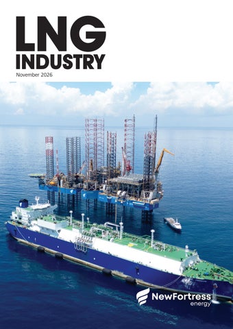
ON THIS MONTH’S COVER Fast LNG is fast-tracking positive energy. By transforming three repurposed jack-up rigs into the world’s first near-shore, platform-based LNG export facility, NFE reimagined what is possible. Today, Fast LNG operates at 127% of nameplate capacity on an annual basis – proof that innovation does not stop at first cargo.
Copyright © Palladian Publications Ltd 2026. All rights reserved. No part of this publication may be reproduced, stored in a retrieval system, or transmitted in any form or by any means, electronic, mechanical, photocopying, recording or otherwise, without the prior permission of the copyright owner. All views expressed in this journal are those of the respective contributors and are not necessarily the opinions of the publisher, neither do the publishers endorse any of the claims made in the articles or the advertisements. Printed in the UK.
TRI-SHARK
TRI-CONTROL
TRI-JACK
TRI-CON
TRI-CHECK
TRI-BLOCK
www.zwick-armaturen.de
JESSICA CASEY EDITOR
COMMENT Managing Editor
James Little james.little@palladianpublications.com
Senior Editor
Elizabeth Corner elizabeth.corner@palladianpublications.com
Editor
Jessica Casey jessica.casey@palladianpublications.com
Assistant Editor
Abby Butler abby.butler@palladianpublications.com
Sales Director
Rod Hardy rod.hardy@palladianpublications.com
Sales Manager
Will Powell will.powell@palladianpublications.com
Production Designer
Siroun Dokmejian siroun.dokmejian@palladianpublications.com
Head of Events
Louise Cameron louise.cameron@palladianpublications.com
Marketing and Digital Executive
Sophie Birss sophie.birss@palladianpublications.com
Digital Events Coordinator
Merili Jurivete merili.jurivete@palladianpublications.com
Digital Content Coordinator
Kristian Ilasko kristian.ilasko@palladianpublications.com
Digital Administrator
Nicole Harman-Smith nicole.harman-smith@palladianpublications.com
Administration Manager
Laura White laura.white@palladianpublications.com
Senior Web Developer
Ahmed Syed Jafri ahmed.jafri@palladianpublications.com
LNG Industry subscription rates: Annual print/digital subscription: £120 Subscription claims: Claims for non receipt of issues must be made within 3 months of publication of the issue or they will not be honoured without charge. Applicable only to USA & Canada LNG Industry (ISSN No: 1747-1826, USPS No: 006-760) is published 11 times per year, with one supplemental issue, by Palladian Publications Ltd, GBR, and distributed in the USA by Asendia USA, 701C Ashland Avenue Folcroft, PA 19032. Periodicals postage paid at Philadelphia, PA, and additional mailing offices. POSTMASTER: send address changes to LNG Industry, 701C Ashland Ave, Folcroft PA 19032.
T
he NFL, Apple Music, and Roc Nation have announced that 25-time Grammy Award Winner Jay-Z will performer at the Super Bowl LXI Halftime Show on 14 February 2027 in California.1 Of course, this is not the only noteworthy piece of news that has come out of the US recently. In a bid to boost America’s status as a leading LNG exporter, the Pipeline and Hazardous Materials Safety Administration has published a notice of proposed rulemaking to update and modernise LNG standards for the first time in decades.2 The proposed rule will codify advanced, cost-saving technologies that will enhance safety by enabling operators to adopt modern innovations such as pipe-in-pipe systems, single-walled ASME containers, and membrane storage tanks. Following Edison’s announcement that QatarEnergy has extended force majeure until the end of December,3 US LNG has stepped up to help replace the loss of global supply volumes as a result of the conflict in the Middle East; Cheniere, currently the largest exporter of LNG in the US, has announced that its subsidiaries, Sabine Pass Liquefaction, LLC (SPL) and Corpus Christi Liquefaction, LLC (CCL), have each entered into a long-term LNG sale and purchase agreement (SPA) with QatarEnergy to supply a total of 4 million tpy of LNG through 2054.4 QatarEnergy has also signed a 20-year SPA with Australia’s Woodside Energy for the supply of up to 3 million tpy of LNG for 20 years from the Louisiana LNG project in the US – one of Woodside’s largest-ever LNG sales agreements.5 Moving away from the US, this issue’s regional report from Global Energy Monitor provides an insight into the state of the African LNG market, and how it has been impacted by recent energy crises. One project that has made the news recently is that of Ethiopian Branch of GCL Energy Investment Co., Ltd and Jurong Group signing an LNG contracted construction and toll processing contract for an LNG project in Ethiopia.6 Of the existing LNG facilities in Africa, many – including the four liquefaction facilities that have started operations since 2022 (Coral Sul FLNG, Congo LNG, Hilli Episeyo FLNG, and Greater Tortue Ahmeyim) – use floating LNG (FLNG) vessels. With a growing global demand for energy, FLNG offers a good alternative to more traditional onshore facilities: it doesn’t need quite as much investment, it offers a different option to monetise gas in new regions of the world that are perhaps harder to access, and offers a solution for risk reduction. The November issue of LNG Industry highlights the growing role of FLNG, with articles on the mooring technology being used for Argentina’s first FLNG export facility; why FLNG is becoming increasingly popular as demand for flexible gas infrastructure grows; and the story of Fast LNG, a first-of-its-kind asset that is helping reimagine what an LNG export facility can achieve. Elsewhere, all eyes will be on Antalya, Türkiye, where COP31, the United Nations Climate Conference, is being held in November 2026. The world will again come together to agree on the actions to address the climate crisis, with negotiations on issues such as adapting to climate impact and reducing greenhouse gas pollution.7 For the LNG industry, all eyes will be on Istanbul, where the World LNG Summit and Awards will be taking place from 1 – 4 December 2026, and awards for Outstanding Contribution, Energy Transition, Executive of the Year, and Shipping will be handed out. You can also pick up a copy of the November issue of LNG Industry at the show.
References
A full list of references is available on request.
Editorial/Advertisement Offices, Palladian Publications Ltd 15 South Street, Farnham, Surrey, GU9 7QU, UK
Tel: +44 (0) 1252 718 999
Website: www.lngindustry.com
WHEN LNG FACILITIES NEED ANSWERS, THE WORLD TURNS TO ZEECO More Locations. More Capabilities. One Partner. With 30+ locations worldwide and nearly 50 years of combustion and emissions control leadership, Zeeco helps LNG facility operators meet today’s flaring and vapor control challenges. The recent acquisition of Oil & Gas Technologies, known for vapor recovery systems, loading systems, terminal automation, and engineered packaged solutions throughout Australia and the Asia-Pacific region, further expands Zeeco’s global end-to-end emission control capabilities for LNG. Trust your most demanding vapor recovery, vapor combustion, compliance support, or rental equipment challenges to the world leader in advanced combustion and environmental technologies.
Zeeco: Choose the World Leader FIND OUT MORE
SALES@ZEECO.COM +1 918.258.8551 BURNERS
|
FLARES
|
THERMAL OXIDIZERS
ZEECO.COM/VAPOR-CONTROL |
VAPOR CONTROL
|
RENTALS
|
AFTERMARKET
|
GLOBAL FIELD SERVICES
|
COMBUSTION ELECTRONICS
©2026 Zeeco, Inc. All rights reserved. ZEECO, ZEECO, INC, the flaming Z logo are registered trademarks of Zeeco, Inc. in the US and other jurisdictions.
LNGNEWS Cyprus USA
MARAD approves deepwater port license application for ST LNG
U
.S. Transportation Secretary, Sean P. Duffy, has announced that the Maritime Administration (MARAD) has approved a deepwater port license application for ST LNG, LLC. The US$8.2 billion deepwater LNG port will support 2000 construction jobs and up to 855 permanent jobs; expand America’s LNG export capacity by 7 – 9%; and feature four 2.1 million tpy liquefaction systems. The ST LNG deepwater port will be built approximately 10.4 miles offshore Matagorda, Texas. Construction is expected to begin in 2027, with the port coming online in 2029. At full capacity, the port will include 20 platforms, four LNG floating storage units, four mooring systems, and 7.7 miles of pipeline. The port location is expected to move vessel traffic away from more congested onshore areas, reducing vessel collisions and safety risks. The feedgas for the port will come from the Tres Palacios Natural Gas Storage and Trading Hub and the Williams Markham Gas Processing Plant through an existing Transco pipeline approximately 5.6 miles northeast of the port.
Eni launches Cronos project execution phase
E
ni has signed the main EPC and drilling contracts for the development of the Cronos project. The execution phase was formally launched in Nicosia during a ceremony attended by the President of the Republic of Cyprus, Nikos Christodoulides, the Minister of Energy, Commerce, and Industry of the Republic of Cyprus, Michael Damianos, and Eni Chief Operating Officer Global Natural Resources, Guido Brusco. The awarded contracts include floating control unit, transportation and installations, offshore sealines, subsea production system, flexible lines, umbilicals, onshore line EPC, and drilling rig services. This follows the final investment decision reached on 28 July 2026 for the development of the Cronos gas discovery in Block 6 offshore Cyprus. Based on gas resources estimated at more than 3 trillion ft3 of gas initially in place, the project is expected to reach a production plateau of up to 500 million ft3/d, with start-up expected in 1H28. The development will leverage a fast-track approach based on regional integration and the use of existing infrastructure. Gas produced from Cronos will be transported to Egypt, where it will be processed through existing facilities, including the Zohr infrastructure, before being liquefied at the Damietta LNG plant for export to international markets, primarily Europe.
Switzerland
WinGD secures long-term service contracts covering 14 dual-fuel LNG carriers
W
inGD has secured three long-term service agreements covering 14 dual-fuel LNG carriers. The agreements with leading LNG ship managers demonstrate growing industry confidence in OEM-led lifetime support and mark significant progress in the expansion of WinGD's global service business. The service package includes spare parts for scheduled maintenance, technical labour, workshop services, and advisory support, alongside remote monitoring, troubleshooting, and engine optimisation through WinGD's WiDE platform. The recent contract wins include a 10-year agreement with COSCO Shipping LNG (Hong Kong) Ship Management covering six LNG carriers powered by WinGD 6X72DF engines.
WinGD has also signed a five-year service agreement with Japan's NYK LNG Shipmanagement covering 10 X-DF dual-fuel main engines across five LNG carriers. The fleet spans several generations of X-DF technology. Two vessels, built in 2022 and 2024 at HD Hyundai Heavy Industries (HHI) and Samsung Heavy Industries, respectively, are powered by WinGD 5X72DF engines, while three newer vessels, built in 2025 and 2026 by HHI, are equipped with 5X72DF-2.1 engines. In Greece, WinGD has signed a long-term engine service agreement covering three newbuild LNG carriers operated by Athens-based TMS Cardiff Gas Ltd. Built by HD Hyundai Samho in South Korea, the vessels are each equipped with two WinGD 5X72DF dual-fuel engines.
November 2026
5
LNGNEWS Canada
SEFE and Ksi Lisims LNG sign supply agreement
F
ollowing the signing of a heads of agreement earlier in 2026, SEFE Securing Energy for Europe has entered into a long-term LNG supply agreement with Canada’s Ksi Lisims LNG. Under the agreement, SEFE will purchase 1 million tpy of LNG on a free-on-board basis for 20 years, with deliveries expected to commence in the early 2030s. The agreement marks SEFE’s first supply partnership with Canada and further expands the company’s diversified global LNG portfolio. The destination-flexible volumes will strengthen SEFE’s ability to serve customers across international markets while contributing to energy security and supply resilience. Ksi Lisims LNG is being developed by Western LNG, Rockies LNG, and the Nisga’a Nation as a low-emission LNG export venture that combines Canada’s abundant gas resources with renewable hydropower. In addition, the partnership with the Nisga’a Nation ensures long-term economic opportunities for local communities and reflects a collaborative approach to developing major energy infrastructure.
USA
PHMSA to modernise LNG regulations
U
.S. Transportation Secretary, Sean P. Duffy, has announced that the Pipeline and Hazardous Materials Safety Administration (PHMSA) published a notice of proposed rulemaking (NPRM) to update LNG standards for the first time in decades. The NPRM updates PHMSA’s safety framework for LNG facilities by incorporating the National Fire Protection Association (NFPA) Standard 59A (2026 edition) for the siting, design, construction, operation, and maintenance of LNG facilities. The update will fast-track new LNG infrastructure projects, lower energy costs, expand export capacity, and boost America’s status as a global energy powerhouse. The proposed rule will codify advanced, cost-saving technologies that will enhance safety by allowing operators to seamlessly adopt modern innovations like pipe-in-pipe systems, single-walled ASME containers, and membrane storage tanks. Leveraging these technologies will generate US$100 million in savings annually.
6
November 2026
Japan
KEYS Azalea completes 100th LNG bunkering operation
K
EYS Azalea, an LNG bunkering vessel owned and operated by KEYS Bunkering West Japan Ltd, has completed its 100th LNG fuel supply by bunkering the bulk carrier SG Dawn, operated by NYK Line. Since conducting its first ship-to-ship LNG bunkering operation in western Japan in April 2024, KEYS Azalea has supplied LNG fuel to a wide range of LNG-fuelled vessels, including car carriers, bulk carriers transporting iron ore and coal, and cruise ships. Assuming all LNG supplied to date has been used as a substitute for the heavy fuel oil traditionally used in marine transportation, the carbon dioxide emissions reduction is estimated to be approximately 75 000 t, based on an equivalent energy input comparison.
THE LNG ROUNDUP X Summit LNG completes 300th ship-to-ship transfer X Rystad Energy: Global LNG importers to spend US$39 billion more in 2026 while buying less X Edison: QatarEnergy extends force majeure until the end of December X Woodside signs 20-year LNG supply agreement with QatarEnergy X Bright Renewables and Nordsol partner for Vireo's bio-LNG plant Follow us on LinkedIn to read more about the articles
www.linkedin.com/showcase/lngindustry
scan to watch video
LNGNEWS South Korea 16 – 18 November 2026
Norton Rose Fulbright advises Crédit Agricole CIB on JOLCO and bridge financing
Florida, USA
N
LNG Bunkering Summit North America www.oilandgasiq.com/events-lngbunkeringna
18 November 2026
Global Hydrogen Conference 2026 Online www.accelevents.com/e/global-hydrogenconference-2026
01 – 04 December 2026
World LNG Summit & Awards 2026 Istanbul, Türkiye
orton Rose Fulbright has advised Crédit Agricole Corporate and Investment Bank (CACIB) and a syndicate of international banks on a US$488.5 million JOLCO and bridge-loan financing of two newbuild 174 000 m3 LNG vessels currently under construction at Samsung Heavy Industries. The cross-border transaction comprised a conventional post-delivery JOLCO financing combined with a pre and post-delivery bridge financing. Both financings incorporated innovative funding mechanics to allocate delivery funding to either the bridge financing or the JOLCO depending on various external factors at the time of delivery of each vessel. CACIB acted as bookrunner, while CACIB, SMBC, Standard Chartered, and OCBC acted as mandated lead arrangers and lenders. The Norton Rose Fulbright team was led by London Partner, Matthew Bambury, supported by Associate, Rheya Panjwani, and Trainee, Pranjal Pande. The Paris team comprised global Co-Head of Transport, Christine Ezcutari, and Associates, Myriam Djoudi and Emilie Jacques.
Germany
www.worldlngsummit.com
Deutsche ReGas restores full capacity
08 – 10 December 2026
NISTM's 19th Annual National Aboveground Storage Conference & Trade Show Texas, USA www.nistm.org/events.html
01 – 02 March 2027
13th International LNG Congress (LNGCON) 2027 Amsterdam, the Netherlands https://lngcongress.com
D
eutsche ReGas and Mitsui O.S.K. Lines (MOL) have entered into a strategic partnership to restore a regasification capacity of up to 13.5 billion m3/y at Germany’s only privately-financed LNG terminal. In the winter of 2027/2028, MOL will provide an additional FSRU for the Deutsche Ostsee (German Baltic Sea) energy terminal. Once commissioned, the Deutsche Ostsee energy terminal will return to its full, permitted regasification capacity, utilising two FSRUs. The charter agreement for the FSRU was signed in October 2026 by Ingo Wagner, CEO of Deutsche ReGas, and Suryan Wirya-Simunovic, Managing Executive Officer for the MOL Europe and Africa region, in the presence of Jotaro Tamura, President and CEO of the MOL Group. Prior to its commissioning at the Deutsche Ostsee energy terminal, the FSRU is being converted from an LNG carrier into a regasification vessel, in accordance with the latest technical and environmental standards.
09 – 10 March 2027
StocExpo 2027
Rotterdam, the Netherlands www.stocexpo.com
07 – 11 June 2027
Nor-Shipping 2027
Cheniere signs long-term SPA to supply QatarEnergy through 2054
C
Lillestrøm, Norway https://nor-shipping.com
08 – 10 June 2027
Global Energy Show Canada 2027 Calgary, Canada www.globalenergyshow.com
8
USA
November 2026
heniere Energy, Inc. has announced that its subsidiaries, Sabine Pass Liquefaction, LLC (SPL) and Corpus Christi Liquefaction, LLC (CCL), have each entered into long-term LNG sale and purchase agreements (SPAs) with QatarEnergy to supply a total of 4 million tpy of LNG through 2054. Under the SPAs, QatarEnergy has agreed to purchase 2 million tpy of LNG from each of SPL and CCL on a free-on-board basis for a purchase price indexed to the Henry Hub price plus a fixed fee. Deliveries under the SPAs will begin in the early 2030s and continue through the end of 2054, with 1 million tpy of the SPL SPA subject to a positive final investment decision with respect to the first phase of the SPL Expansion Project.
Learn more
Recent energy crises have raised the value of cargoes from Africa’s existing LNG plants but have done little to advance delayed projects. Floating vessels and looser contract terms shift risk rather than remove it, and new export capacity remains a risky long-term bet with public money at stake, argues Baird Langenbrunner, Project Manager, Global Energy Monitor.
10
A
frica’s cautionary tale for aspiring LNG exporters starts in Cairo. Two decades ago, Egypt began building gas infrastructure to ship LNG to the world. Today, it pays to bring gas back in. The country’s two large liquefaction plants, Idku and Damietta, were built in the mid-2000s to export Egyptian gas. Domestic demand then rose, offshore supply declined,1 and the plants spent years underused or idle. By 2024, Egypt was a net gas importer.2 In 2025, it imported a record 8.9 million t of LNG, about 91% of it from the US.3 Today, Egypt still exports when domestic supply allows, but the flows are small and intermittent. The country exported 162 000 t in 1Q264 after shipping out none in 2025. Exports stopped again in March 2026 when piped gas from Israel was disrupted, before resuming in April. And these terminals could serve someone else soon. In July 2026, TotalEnergies and Eni
approved the development of the Cronos gas field in Cyprus. When it begins production in 2028, gas will be piped to Egypt and exported out of Damietta. Currently, the Mediterranean port is recovering from a drone strike, which occurred at the end of July 2026 and resulted in a fire on an FSRU chartered by US-based New Fortress Energy, though had no wider explosions or fatalities. As the Egyptian experience foretells, an export terminal and domestic gas reserves do not guarantee dependable export revenue. African governments and developers are still advancing large scale projects expected to operate for decades, requiring long-term offtake agreements to anchor such big investments, even as global gas supply expands. The projects that have actually reached production look nothing like the ones still in development.
11
Floating LNG limits developers’ risk, but not Africa’s
Global Energy Monitor tracks 17 operating LNG terminal projects across Africa, including import and export facilities. It puts the export facilities’ combined capacity at about 80 million tpy, roughly 15% of the global total. With Coral North now under construction, another 21.4 million tpy of African export capacity is being built across four projects. A further 62.5 million tpy remains proposed across 11 projects. The few export projects that have recently moved forward differ from the large onshore plants still on the drawing board. All four African liquefaction facilities that started operating since 2022 use floating LNG (FLNG) vessels. Coral South has operated off Mozambique since 2022; Congo LNG has added two floating units, the second of which began operating in February 2026; and Greater Tortue Ahmeyim, on the maritime border of Mauritania and Senegal, shipped its first cargo in April 2025. Coral North, a 3.6 million tpy floating project now under construction for Mozambique, is scheduled for completion in 2028. The Greater Tortue Ahmeyim terminal and Congo LNG’s two floating units together accounted for just over 8% of Africa’s LNG exports in 1Q26. Small floating export projects typically cost less and take less time to build than onshore projects, particularly when converted LNG carriers are used, according to a World Bank analysis.5 That can reduce developers’ exposure during construction, but the central asset is a vessel that can move around, and who owns the vessel is not always the country supplying the gas. The floating Hilli Episeyo export terminal, for example, operated at Cameroon FLNG from 2018 until its charter expired in July 2026 and Golar declined to renew it, citing a capacity cap. The vessel was disconnected in August and sent to Singapore for upgrades, ahead of a 20-year deployment to Argentina, where it is due to arrive by mid-2027. Unless a new charter is secured, Cameroon FLNG will cease operations by the end of the year.
The terms determine who carries the risk
Long-term sales agreements remain central to LNG finance. By committing buyers for years, they provide the predictable revenue developers use to secure loans. But they can also leave buyers paying for fossil fuels after their demand or energy policy changes. Agreements lasting at least 10 years accounted for 75% of LNG volumes contracted since 2022.6 The duration of these agreements is not changing as quickly as their other terms. Traditionally, many LNG contracts set the price of gas using a formula tied to the price of oil, even though oil and gas markets can move differently. More contracts now link their prices to gas markets,6 such as Henry Hub in the US or TTF in Europe, or use a formula that combines gas and oil prices. The International Energy Agency (IEA) expects destination-free agreements, which allow cargoes to be redirected or resold, to cover just over half of contracted LNG volumes by 2030.6 These changes do not place all the risk on one side. A buyer may be committed to paying for gas but is free to resell it elsewhere, and a producer may have dependable sales but receive a price tied to a volatile market benchmark. Who benefits when prices rise, and who loses when
12
November 2026
demand falls, depends on the agreement’s pricing, purchase, delivery, and resale terms. That uncertainty matters for African projects competing with expanding supply from the US and Qatar. New terminals still need customers willing to make long-term commitments, but those customers will have more suppliers to choose from and can demand more favourable terms. High borrowing costs and political and security risks can further increase the cost of African projects. At Greater Tortue, the published working interests (BP at 56%, Kosmos Energy at 27%, and the national companies of Senegal and Mauritania at 10% and 7%, respectively) refer to the gas development. Separately, BP Gas Marketing agreed to buy the project’s Phase 1 LNG output for up to 20 years. But the contract’s terms are not public, so the rights to redirect or resell cargoes and the way any resulting gains are shared remain unknown.
Two crises, little room to respond
Two recent crises have shown what those terms are worth. After Russia invaded Ukraine in 2022, African producers responded to Europe’s search for replacement gas mainly by redirecting existing supplies and signing agreements for future projects. For example, Algeria sent more pipeline gas to Italy, while Egypt limited domestic electricity use to free up gas for export and signed an agreement with Israel and the EU to increase LNG sales. Little new production arrived in time, however, meaning Africa was expected to fill the gap with the meagre domestic production already in place. Nigeria’s LNG export terminals were operating at only 68% capacity, Mozambique’s large onshore projects were stalled, and projects in Congo and Mauritania would not begin exporting for several more years. The ongoing crisis in the Strait of Hormuz has produced a different shock since early 2026. The closure disrupted LNG flows that accounted for almost one-fifth of global supply,7 pushing spot prices in Asia and Europe to their highest monthly averages since January 2023. The increase was particularly strong in Asia, where LNG prices averaged US$0.90/million Btu below European prices in January and February 2026, then US$2.10 above them from March through June.7 The effect of the price shift could be seen in shipping routes. Two LNG carriers, BW Brussels and Pan Americas, were loaded at Nigeria’s Bonny Island complex and initially headed towards Europe. After Asian prices rose above European prices, both ships were redirected to Asia in early March 2026, despite the longer journey around the Cape of Good Hope. The change of course showed the value of flexible cargoes to the companies that control them; they could send the gas to whichever market paid more. But none of this reveals how much of the higher price, if any, remained in Nigeria. The Hormuz crisis therefore raised the value of LNG that African plants could already deliver. It did not accelerate the development of large projects that remain years from production, some after repeated delays.
Large projects facing a crowded market
Mozambique LNG, a US$20 billion onshore project whose development was halted after an insurgent attack in 2021, restarted work in January 2026 and is not expected to produce
before 2029. The neighbouring Rovuma project has lifted the force majeure declaration that paused work, and the project’s developers recently awarded US$1.1 billion in equipment contracts, with final investment decision expected by year end, but production is not targeted until around 2030. Tanzania’s US$42 billion export project still awaits a signed agreement between the government and its developers. Before Hormuz, a wave of new LNG projects, led by the US and Qatar, was expected to add more supply than demand could absorb by 2030.6 The crisis has pushed that prospect further into the future. The IEA now estimates that the conflict could remove 140 billion m3 from the LNG supply previously expected through 2030, with most of the losses concentrated in 2026 and 2027.7 The construction wave has not disappeared. The IEA’s current capacity tracker lists about 345 billion m3/y of new export capacity scheduled to come online between 2025 – 2030 from projects already under construction. Even with the losses caused by Hormuz, the added capacity will increase competition among exporters later in the decade.
Public money and competing priorities
African public institutions are now being asked to finance part of this expansion. The Africa Energy Bank, established by the African Petroleum Producers’ Organization (APPO) and Afreximbank, was scheduled to open in Abuja in September 2026, after several postponements, and begin lending by the end of the year. APPO says the bank is expected to start with US$500 million in start up capital, split equally between Afreximbank and APPO and its member countries. The bank plans to finance 20 – 30 LNG, pipeline, terminal, and refining projects by 2030, with gas expected to account for about 40% of its loan book. Supporters argue that the bank will keep more investment in Africa, create jobs, and give African governments greater control over energy development. But its initial funding would direct money from African governments and a multilateral financial institution towards fossil fuel assets that can take years to build and could operate for decades. The LNG projects among them would face an increasingly competitive export market. If construction costs rise, buyers find cheaper suppliers, or demand falls short, the bank and its shareholders could bear the losses. That matters in sub-Saharan Africa, where average public debt nearly doubled between 2013 and 2022, from 30% to almost 60% of economic output.8 Africa’s need for energy investment is clear. Around 600 million people still lack electricity,9 but electricity access and gas development are not the same goal. An LNG export plant primarily serves foreign buyers. An import terminal requires a country to keep buying fuel while also paying for shipping, regasification, pipelines, and power plants. Neither of these necessarily pays for the transmission and distribution networks needed to connect homes and businesses. Where electricity is the objective, governments can compare the full cost of gas infrastructure with renewable generation, storage, and grid expansion before accepting long-term fuel or charter commitments. Globally, more than 90% of utility scale renewable projects commissioned in 2025 were cheaper than the lowest-cost new fossil fuel plant in their market.10 Solar equipment is also largely imported,
14
November 2026
but an installed solar plant does not require ongoing fuel purchases, nor does it expose consumers to disruptions in global fuel markets and shipping. Africa has 60% of the world’s best solar resources,11 yet attracts less than 2% of global clean energy spending.12 Solar power cannot meet every energy need on its own. Electricity systems also need stronger grids, storage, and in some cases, dependable power sources beyond solar. Some industries use gas as a feedstock. But those needs do not justify every proposed LNG terminal or export plant. The experience of Egypt and Africa’s delayed export projects shows that gas reserves and infrastructure do not automatically produce affordable energy, reliable revenue, or energy security. Each project is a long-term commercial bet whose costs may outlast the market conditions used to justify it. The Hormuz crisis briefly increased the value of African LNG by disrupting competing supplies. It did not show that every proposed project will be completed in time for the next shortage or earn enough during occasional price spikes to repay decades of investment. Before committing public money, governments can require developers to identify who will buy the gas, when the project can begin operating, what benefits will remain in the host country, and who will bear the losses if costs, demand, or prices move in the wrong direction.
References 1.
‘Offshore discoveries in the Mediterranean could increase Egypt’s natural gas production’, U.S. Energy Information Administration (EIA), (14 August 2018), www.eia.gov/ todayinenergy/detail.php?id=36792
2.
‘Growing natural gas deficit leads Egypt to ramp up natural gas imports’, EIA, (9 September 2025), www.eia.gov/ todayinenergy/detail.php?id=66064
3.
STEVENSON, P., ‘Egypt LNG Imports: Record 2025, More to Come in 2026’, Mees, (2 January 2026), www.mees. com/2026/1/2/refining-petrochemicals/egypt-lng-importsrecord-2025-more-to-come-in-2026/691f0f70-e7dd-11f0-acc61d86dba5c11b
4.
KÉFI, W., ‘Africa’s LNG Exports Climb 27% in Early 2026, Driven by Supply Shifts’, Ecofin Agency, (21 April 2026), www.ecofinagency.com/news/2104-54862-africa-s-lng-exportsclimb-27-in-early-2026-driven-by-supply-shifts
5.
‘Project Information Document/Integrated Safeguards Data Sheet’, The World Bank, (3 February 2017), https://documents1. worldbank.org/curated/en/363321486544037780/pdf/ ITM00184-P160652-02-08-2017-1486544035417.pdf
6.
‘Gas 2025: Analysis and forecasts to 2030’, International Energy Agency (IEA), (27 October 2025), www.iea.org/reports/ gas-2025
7.
‘Gas Market Report, Q3-2026’, IEA, (7 July 2026), www.iea.org/ reports/gas-market-report-q3-2026
8.
COMELLI, F, et al., ‘How to Avoid a Debt Crisis in Sub-Saharan Africa’, International Monetary Fund, (26 September 2023), www.imf.org/en/news/ articles/2023/09/26/cf-how-to-avoid-a-debt-crisis-in-subsaharan-africa
9.
‘Financing Electricity Access in Africa’, IEA, (20 October 2025), www.iea.org/reports/financing-electricity-access-in-africa
10. ‘Renewable power generation costs in 2025’, International Renewable Energy Agency, (July 2026), www.irena.org/ Publications/2026/Jul/Renewable-Power-Generation-Costsin-2025 11. ‘Clean Energy Investment for Development in Africa’, IEA, (13 June 2024), www.iea.org/reports/clean-energy-investmentfor-development-in-africa 12. ‘Financing Clean Energy in Africa’, IEA, (6 September 2023), www.iea.org/reports/financing-clean-energy-in-africa
New Fortress Energy, USA, showcases the story of a first-of-its-kind asset that is challenging conventional thinking and rewriting the playbook for what an LNG export facility can achieve.
F
or decades, the LNG industry has asked the same question of every new project: how big can it be built? Mega-trains, onshore terminals, and conventional floating LNG vessels have delivered enormous volumes, but at the cost of long schedules, heavy capital commitments, and first gas arriving five, seven, or even 10 years after a final investment decision. NFE asked a different question: how fast can reliable LNG be brought to market? The answer is Fast LNG, the facility now operating offshore Altamira, Mexico. It is a fully-integrated, standalone, modular mid scale liquefaction facility with a nominal capacity of 1.4 million tpy, built on three repurposed marine jack-up rigs. Utilities, accommodation, gas treatment, and liquefaction all sit offshore, together with a marine export facility. Nothing like it had been built before.
16
Approximately 44 months after the first phone call between NFE and Fluor, the facility loaded its first cargo. Within months of start-up, it was producing above its nameplate capacity. More than two years into operations, it continues to raise its own bar.
First of its kind, by design
Fast LNG is not a conventional project delivered quickly – it is a new category of asset. Several firsts came together in a single facility: z Repurposed jack-up rigs as the foundation: Rather than fabricating a new hull or building an onshore plot, NFE used three existing jack-up rigs as stable, proven offshore platforms. Their legs rest on the seabed, eliminating the motion challenges of a floating hull and the need for a purpose-built shipyard slot.
Figure 1. Fast LNG infrastructure was fabricated at a Kiewit site in Corpus Christie, Texas, the US.
17
z The largest single mixed refrigerant (SMR) modular mid scale LNG train of its kind: Fast LNG employs an SMR liquefaction process at a scale that had not previously been deployed in a modular mid scale configuration, combining the simplicity of SMR with output large enough to matter in the global market. z A complete facility, offshore: Gas treatment, mixed refrigeration, LNG production, hot oil and power systems, utilities, and living quarters are fully integrated across the three platforms, with no dependence on an onshore process infrastructure. z Air-cooled, modular, and repeatable: Standardised modules were fabricated in parallel and installed on the platforms, creating a design that can be replicated for future units rather than re-engineered from scratch. Each of these choices on its own would be notable. Together, they produced an asset that has no direct peer in the LNG space.
Speed to market: From concept to cargo
Time is the most expensive variable in any LNG project. Every year between concept and first cargo is a year of capital deployed without revenue and a year in which market conditions can shift. Fast LNG managed to dramatically compress that timeline. The approach was built around parallel execution. While engineering progressed, the jack-up rigs were being prepared, long-lead equipment was secured, and modules were fabricated at multiple sites at the same time. Using existing platforms removed one of the longest critical-path activities in offshore development. A modular, standardised design meant fabrication could proceed in controlled yard environments, with offshore work focused on installation, hook-up, and commissioning. The result was approximately 44 months from first phone call to first cargo, a fraction of the timeline typical of conventional liquefaction projects. For gas resource holders and LNG buyers alike, that speed changes the economics of what is possible: stranded or associated gas can be monetised years earlier, and supply can respond to demand while the opportunity still exists.
A robust design, proven in operation Speed is only valuable if the asset that results is safe and dependable. From the outset, the Fast LNG design prioritised robustness alongside schedule.
Jack-up rigs offer a fixed, stable foundation in shallow water, giving process equipment a steady operating environment closer to that of an onshore plant than a floating vessel. The SMR process is inherently simpler than more complex multi-refrigerant cycles, with fewer major rotating machines and a smaller equipment count, which translates into fewer potential points of failure and a more straightforward facility to operate and maintain. Modular construction allowed each module to be built and tested to a high standard before leaving the yard. Safety was the overarching consideration in every decision, from layout and spacing on the platforms to the operating philosophy adopted during commissioning. That discipline has carried through into operations.
Commissioning and start-up: Turning early lessons into lasting improvements
Being first has a consequence: there is no operating manual written by someone else. NFE became the first owner-operator of this type of facility, and its teams had to learn about the plant as they brought it to life. First LNG was achieved in July 2024, with the first cargo following shortly after. The commissioning and initial operating period was approached as both a start-up and a structured learning programme. Every trip, outage, and performance trend was captured, analysed, and fed back into the operating strategy. That disciplined approach to data allowed the team to identify quickly where the plant had headroom and where targeted improvements would deliver the greatest return.
World-class people: The power of combined expertise
A first-of-its-kind asset demands a first-rate team. Fast LNG sits at the intersection of two demanding disciplines – offshore operations and LNG liquefaction – and very few organisations combine deep expertise in both. NFE’s operations, maintenance, and technical teams bring together offshore professionals experienced in marine platforms, jack-up operations, logistics, and offshore safety with LNG specialists experienced in gas treatment, refrigeration cycles, cryogenic equipment, and LNG export. Working side by side on the same platforms, these employees have built an operating culture that combines the rig of the company’s offshore work with the process precision LNG requires. That combination of skills has been central to every milestone: commissioning a novel plant safely, diagnosing issues no one had encountered before, and continually optimising performance. The technology makes Fast LNG possible; the people make it work.
When performance exceeds design
By early 2025, within months of first cargo, NFE reported that the facility was operating approximately 20% above its nameplate capacity. For any new LNG facility, exceeding design output this early would be notable. For a first-of-its-kind asset, it is a clear validation of the concept. NFE did not treat this as a ceiling. Together with Fluor, the team launched a comprehensive programme to secure, optimise, and further increase production based on the lessons of the first year. The evaluation covered every major system on the facility:
Figure 2. In November of 2023, FLNG 1 achieved first gas.
18
November 2026
z Facility systems: Natural gas feed, gas treatment, mixed refrigeration, LNG, hot oil, and utility systems.
Courtesy of Bioplus LNG GmbH
Complete LNG Technology for All Gas Sources Maximize Value from Your Natural Gas Streams Small Scale LNG systems are designed to liquefy fossil derived and synthetic natural gas, biomethane derived RNG. Whether for remote distribution, heavy-duty transport, peak shaving or off-grid power generation, SIAD has the LNG liquefaction technology that meets your needs. • Broad product range Standard and customized designs • Fully modularized Less installation time and faster on stream • Cost-effective Energy efficient, low total CAPEX • Productivity optimized Remote monitoring and control available • Enhanced sustainability Utilization of wasted gas, biomethane liquefaction, carbon capture and liquefaction.
Global presence, local support. Contact us to speak to a SIAD specialist in your region.
siadmi.com
For further information: siad_LNG@siad.eu
z Key constraints: Power, heat rejection, equipment design limits, and system hydraulics. z Components: Rotating equipment, vessels, air coolers, heat exchangers, piping, instrumentation, control valves, and pressure safety valves. Operating data, production trends, and planned and unplanned outages were analysed alongside process simulations to pinpoint the physical limits on production. The result was a clear, prioritised set of debottlenecking opportunities, starting with the ‘low-hanging fruit’ that could be captured quickly at modest cost, followed by targeted modifications to unlock further capacity.
Turning operating challenges into performance gains
Two challenges in particular illustrate how the team has turned real-world conditions into improved output. z Ambient temperature: As an air-cooled facility on the Gulf of Mexico coast, Fast LNG sees production vary with the seasons. Cooler months allow higher output, while summer heat constrains heat rejection. Rather than accept seasonal swings as fixed, the team has evaluated and prioritised measures to improve annual performance, focusing on air cooler effectiveness, refrigerant management, and operating set-points that maximise production across the full temperature range. z High-nitrogen feed gas: The facility’s feed gas carries a higher nitrogen content than a typical design basis, which affects refrigeration efficiency, LNG quality, and overall throughput. The NFE and Fluor teams developed operating strategies and design solutions to cope with and mitigate its effects, protecting both product specification and production rates. In both cases, the approach was the same: measure carefully, understand the root cause, and apply practical engineering solutions that deliver more LNG.
Reliability: Less downtime, more delivery
High production means little without consistency. NFE’s philosophy for the second phase of operations has been simple: increase the uptime and decrease the downtime.
That work spans full reliability, availability, and maintainability (RAM) picture. Alarm and trip rationalisation has reduced nuisance trips and given operators clearer, more actionable information. Learnings from early outages have been built into preventive and predictive maintenance programmes. Spares strategy, maintenance planning, and turnaround execution have been refined to reflect how the plant behaves, not just how it was expected to behave on paper. The outcome is a facility that is not only producing high, but doing so reliably, cargo after cargo.
Powering a new path to positive energy
Fast LNG demonstrates that the industry’s traditional trade-offs between speed, cost, scale, and reliability are not fixed. With the right concept, the right partners and the right people, it is possible to have all of them. z Faster to market: Approximately 44 months from concept to first cargo. z Robust by design: A stable jack-up foundation, a simple SMR process, and modular construction built for safety and dependability. z Producing high: Operating above nameplate within months of start-up, with a structured programme to go further. z Reliable: A disciplined RAM programme focused on maximising uptime. z Repeatable: A standardised, modular design that can be deployed again, faster still. For resource holders, Fast LNG offers a way to monetise gas years sooner than conventional projects allow. For buyers, it offers new sources of supply that can respond to market needs while those needs still exist. For the industry, it is proof that innovation in LNG is not limited to incremental improvements on familiar designs.
Looking ahead
More than two years into operations, NFE continues to evaluate further improvements in production, efficiency, and reliability, and to apply what Fast LNG has taught to the next generation of facilities. Every lesson learned at Altamira, from commissioning to debottlenecking to nitrogen management, strengthens the case for the model and makes each future unit faster and better than the last. Fast LNG began with an idea and a single phone call. It became a high-performing, reliable asset that challenged conventional thinking about LNG development. What started as a different way to build LNG has become proof of what is possible when the industry is willing to think differently – and this is only the beginning.
Note
Figure 3. By September of 2024, FLNG 1 achieved its first full cargo and sail away.
20
November 2026
This article is based on a paper presented at Gastech 2026 in Bangkok, Thailand: BORSOS, S. (Fluor) and KADER, R. (New Fortress Energy), ‘The New Fortress Energy Fast LNG Facility: Living with, operating and optimising the ‘Tour de Force’ - the first two years’, Gastech Exhibition & Conference, (September 2026).
CoreMarine, Norway, runs through the mooring technology being used for Argentina’s first floating LNG export facility.
A
s Argentina accelerates its ambition to become a major LNG exporter, a critical piece of the puzzle is taking shape offshore in the San Matías Gulf. The installation of the Hilli Episeyo floating LNG (FLNG) vessel in 2027, followed by the larger MKII Esperanza FLNG unit in 2028, will not only mark the country’s entry into large scale offshore LNG exports, but also introduce a mooring technology never before deployed in Argentinean waters. At the heart of this challenge is an emerging collaboration between offshore specialist, CoreMarine, and installation contractor, Jumbo Offshore. While the Hilli Episeyo project represents the first live offshore execution project delivered jointly by the two companies, the relationship was built
21
during an intensive tendering process that revealed strong technical alignment, complementary capabilities, and shared safety philosophy.
A partnership built around complementary expertise
The contract award reflects CoreMarine’s growing reputation as a trusted partner for complex offshore mooring developments. By leading the engineering, project management, and execution planning from the outset, the company demonstrated an ability to manage the full lifecycle of a technically demanding FLNG installation. Rather than presenting a traditional contractorsubcontractor model, CoreMarine assembled a delivery team designed specifically around the project’s requirements. This included leveraging Jumbo Offshore’s specialist heavy-lift expertise and vessel for the mooring system installation, with the foundation of the proposal CoreMarine’s technical leadership, integrated project approach, and ability to provide Southern Energy with a clear pathway from detailed engineering through to offshore hook-up and pre-commissioning.
More than another mooring project
For CoreMarine, the Argentinean project represents a stepping stone prior to all its mooring jobs, such as assignments on the Firenze FPSO and Toscana FSRU. While those projects showcased the company’s ability to manage critical mooring scopes, the Southern Energy development pushes CoreMarine further up the value chain. The company is responsible not only for engineering and project management, but also for pre-commissioning activities, diving operations, and complex pipe spool work.
This results in a wider role and responsibility for the project and its overall delivery, and directly involves the company in one of the region’s most strategically significant energy projects currently in execution in South America.
Supporting Argentina’s LNG ambitions
The Southern Energy project is widely regarded as a cornerstone of Argentina’s drive to unlock the full export potential of its vast Vaca Muerta gas resources. The development will deploy two FLNG vessels in the San Matías Gulf, beginning with the Hilli Episeyo, which has a liquefaction capacity of approximately 2.45 million tpy, followed by the 3.5 million tpy MKII Esperanza facility. Together, the vessels are expected to provide around 6 million tpy of LNG export capacity, establishing Argentina’s first large scale FLNG export hub. For CoreMarine, the project also carries a degree of continuity. Before the vessel’s relocation to Argentina, the company completed the disconnection of the Hilli Episeyo FLNG offshore Cameroon, delivering a technically complex offshore campaign safely, on schedule, and through a cost-efficient execution strategy. That experience provided CoreMarine with valuable familiarity with the asset and its mooring systems, while demonstrating the company’s capability to manage critical phases across the full lifecycle of floating energy infrastructure. The Hilli Episeyo recently departed Cameroon after eight years of operation and is now heading to Singapore, where it will undergo maintenance and refurbishment before being redeployed to Argentina. The vessel is expected to arrive in the San Matías Gulf in mid-2027, where it will play a pivotal role in launching the country’s LNG export ambitions.
The challenge of installing two FLNG facilities back-to-back
Figure 1. Completed disconnection of the Hilli Episeyo floating LNG (FLNG) platform offshore Cameroon.
Figure 2. The Fairplayer underway carrying the complete soft yoke mooring system and specialised installation equipment required for the offshore mooring of the Hilli FLNG facility. Source: Jumbo Offshore.
22
November 2026
While offshore mooring installations are always complex, this project introduces a unique challenge: two major FLNG facilities will be installed in consecutive years. For the project team, the complexity extends beyond engineering. Logistics may prove equally challenging. The San Matías Gulf region is far removed from traditional offshore construction hubs. Establishing reliable supply chains, mobilising specialist vessels, co-ordinating offshore campaigns, and developing local support capabilities all require meticulous planning. The offshore execution phase will involve simultaneous operations on a scale rarely encountered in emerging offshore regions. Heavy-lift activities, piling operations, riser installation, saturation diving, and vessel co-ordination will all need to be synchronised while maintaining strict safety standards and schedule discipline. The continuity between the 2027 and 2028 campaigns, however, also creates advantages. Lessons learned during the Hilli installation can be rapidly incorporated into the MKII Esperanza deployment, reducing risk and improving efficiency.
First application of SSY technology in Argentina
A defining feature of the project is the deployment of NOV’s subsea soft yoke (SSY) mooring technology.
Unlike conventional offshore mooring systems, the SSY uses a large ballasted yoke that provides restoring force and allows the FLNG vessel to rotate freely with prevailing environmental conditions. This weather-vaning capability makes it particularly suited to offshore LNG operations. Although based on a proven design utilised elsewhere in the world, the system has been adapted to suit the specific
conditions of the San Matías Gulf and the operational requirements of both FLNG vessels. The installation itself presents unique challenges. The yoke must be transported, lifted, and positioned using specialist heavy-lift assets while carefully managing ballast operations to achieve its precise design weight and performance characteristics. Jumbo Offshore intends to deploy its DP2 heavy lift crane vessel, Fairplayer, which will carry the complete SSY system and installation equipment from Europe to Argentina in a single voyage before undertaking the offshore installation campaign.
Technology driving safer operations
One of the most technically demanding phases of the project will be the hook-up of the FLNG vessels to the subsea yoke system. Although comparable in principle to FPSO hook-up operations, FLNG installation introduces additional challenges associated with the geometry and positioning requirements of the submerged yoke system. Maintaining precise vessel alignment, managing tug operations, overseeing heavy-line handling activities, and co-ordinating diving support vessels all require exceptional operational control. To further enhance execution safety, CoreMarine plans to deploy its digital twin technology during installation. The system will provide real-time monitoring of asset positions and vessel motions, improving situational awareness during critical hook-up operations and supporting informed decision-making offshore.
Balancing industrial development and environmental stewardship Figure 3. Loading the base structure of the soft yoke
mooring system aboard Fairplayer, with the yoke visible in the background. Source: Jumbo Offshore.
The San Matías Gulf presents another important consideration: environmental sensitivity. The gulf, located in the Patagonia region, is recognised for its rich marine biodiversity, including seasonal visits by southern right whales. Rather than treating these environmental factors as obstacles, the project team has incorporated them into the engineering and planning process from the outset. This approach reflects the increasing emphasis across the offshore energy industry on minimising environmental impact while maintaining efficient project delivery.
From project to blueprint
Figure 4. Delivering offshore excellence.
24
November 2026
What distinguishes this development is not simply its scale, but what it represents for Argentina’s future. The objective extends beyond installing two FLNG facilities. CoreMarine and Jumbo Offshore see the project as an opportunity to establish a repeatable model for future offshore gas export developments in the region. With Rotterdam serving as the project’s primary European logistics hub and Puerto San Antonio Este acting as its Argentine operational base, the programme combines global expertise with local execution capability. If successful, the Hilli Episeyo and MKII Esperanza installations will do more than launch Argentina into the LNG export market; they could establish a blueprint for how large scale offshore energy infrastructure is delivered in one of the world’s most promising emerging gas provinces.
Anna Apostolopoulou, Global Floating Offshore Installations Director, Lloyd’s Register, explains why floating LNG is becoming increasingly popular as demand for flexible gas infrastructure grows.
F
loating LNG (FLNG) technology has advanced rapidly over the past decade, evolving from early pioneering liquefaction concepts into commercially-proven offshore facilities. Projects such as Petronas’ PFLNG Satu in Malaysia, Shell’s Prelude FLNG in Australia, and the
25
Coral South and Coral North developments in Mozambique show how the technology has steadily matured. Together, alongside a growing pipeline of new developments, these projects have established the technical and commercial foundations for the next generation of offshore liquefaction assets. While early FLNG developments focused primarily on offshore liquefaction and export, the sector today now includes FLNGs, FSUs, and FSRUs, each serving distinct operational and commercial purposes. Their faster deployment compared with fixed installations can also help meet strategic energy requirements. After Russia’s invasion of Ukraine halted pipeline gas supplies to Germany, the country turned to floating import infrastructure and now has four FSRUs in operation, with a fifth expected soon. Elsewhere in Europe, FSRUs are already operating or under development in Croatia, Cyprus, Finland, Greece, Ireland, Italy, Lithuania, the Netherlands, Poland, and the UK. Each project is different, but the development process typically includes:
Export potential
z Business case preparation ahead of a final investment decision (FID).
While FSRUs have drawn significant attention in energy-importing markets, development activity is also accelerating on the export side of the industry. FLNG projects that have already achieved the FID milestone and are now under development include Coral North LNG and Mozambique LNG. In early June 2026, Technip Energies, together with JGC Holdings and Samsung Heavy Industries, was awarded an EPCIC contract for Coral North. With a capacity of 3.6 million tpy, the project will effectively double Mozambique’s total Coral output to 7 million tpy. Other projects under development include Genting FLNG in Indonesia, Petronas FLNG 2 in Malaysia, and two Southern Energy FLNG phases in Argentina. Together, they are expected to add almost 16 million tpy of capacity when they come on stream this decade. This additional production would almost double current operating FLNG capacity, with further projects already at the feasibility study stage.
z Classification assurance and approvals.
Southern Europe on a roll
z Initial feasibility study. z Project design and development. z Asset selection – newbuild or conversion.
z Commissioning. z Through-life condition monitoring, surveys, service, and operational oversight.
Rapid expansion in progress
In addition to the eight FLNG facilities already in operation, nine more are under development, more than doubling current liquefaction capacity of 16.7 million tpy; Rystad Energy forecasts capacity will increase to 42 million tpy by 2030 and 55 million tpy by 2040. These facilities liquefy natural gas offshore, while other floating LNG assets, including FSRUs and FSUs, are also operating or under development across global LNG supply chains. Together, they provide critical links from offshore production and liquefaction to storage, transportation, and regasification. FLNG facilities can offer major advantages over fixed infrastructure, with speed of deployment often the most important. In August 2022, for example, the Soviet Union suspended gas exports to Germany, citing maintenance and repair issues. Germany had already started converting the LNG carrier, Höegh Esperanza, and recommissioned it as an FSRU that December, just 10 months after the conversion began. Although Germany is an exceptional case, it shows how deployment speed can affect both time to production and project cash flow. Supply disruption and regional instability in various producing regions have highlighted the strategic importance of flexible LNG infrastructure for both exporting and importing nations.
26
Since FSRUs can be built and commissioned far faster than shoreside terminals, they can serve as strategic interim infrastructure ahead of permanent land-based facilities. At Brunsbüttel, LNG is currently imported via the FSRU Höegh Gannet operated by Deutsche Energy Terminal. Once construction of a purpose-built jetty is completed, the unit will be relocated to operate alongside it before eventually being replaced by a permanent import terminal, as per current plans.
November 2026
Activity is also increasing across the Mediterranean. In Cyprus, an FLNG project under development will use a unit converted at COSCO in China. In Greece, the Gastrade-operated Alexandropoulis FLNG processes LNG to gas for delivery to markets in southern Europe and the Balkans. Turkey has three FSRUs in operation – the Ertuğrul Gazi FSRU at the Botas Dörtyol LNG terminal in Hatay; the Turquoise P at the Ekti LNG terminal in Iszmir, and the Saros FSRU terminal in the northwest of the country. As FLNG development continues to accelerate, existing LNG carriers suitable for conversion will be in high demand. There are a large number of vessels that are powered by steam turbine engines with poor fuel consumption that cannot compete effectively with latest generation vessels in today’s market. As a result, they trade at a steep discount to vessels powered by dual-fuel or tri-fuel diesel-electric systems, or slow-speed dual-fuel engines. Many of these steamers have recently made their final voyages to recycling yards on the Indian subcontinent, although their complexity means they can still retain significant end-of-life value. For owners of steamers still in good condition, conversion for FLNG use offers an attractive alternative, generating stronger returns while extending the useful life of these assets.
Feasibility and robust assurance
As the FLNG sector expands, across both export projects and FSRU import infrastructure, its highly complex developments demand careful planning, rigorous due diligence, and robust assurance. Close collaboration with clients is essential,
and Lloyd’s Register (LR) brings extensive experience across both newbuild and conversion projects. Texas-based Excelerate, for example, has so far favoured newbuilds over conversions, but the energy company is not a shipowner and can purpose-design new units for specific project requirements. By contrast, LNG shipowners may have older vessels that offer good conversion options, extending asset life, and generating an additional revenue stream. Norwegian LNG carrier owner and LR client, Knutsen OAS Shipping, has already converted several steam turbine-powered LNG carriers into floating units and has more suitable candidates in its fleet. The company recently completed an FSU conversion at Hyundai in South Korea in just six months. The asset is due to be deployed in Honduras, with a second conversion now planned. LR’s multi-faceted assurance process provides the flexibility needed for conversion projects involving older, less fuel-efficient steamers that now trade at deep discounts. It also supports newbuild projects through techno-commercial studies that assess likely investment returns. Beyond project development, LR focuses on asset operation to help maximise uptime. Membrane cargo tanks are a case in point. Through its work with cargo tank specialist GTT, LR has helped develop an approach to extend intervals between tank openings. As opening tanks is time-consuming and removes assets from service, longer intervals can deliver immediate gains in profitability and operational efficiency.
LR also helps develop effective operating procedures through close monitoring of topsides, hull, and regasification systems, supported by risk assessment and criticality analysis. This work can underpin survey notations that allow assets to remain on station instead of being withdrawn for five-year dockings. For units permanently assigned to a specific site, intervals can be extended as appropriate, subject to the operational profile of the asset and subject to agreement with the flag state and classification society.
Proving long-term performance
FLNG has moved from the margins of the LNG business to become one of its most strategically important growth areas. FLNG, FSUs, and FSRUs now offer governments, producers, and buyers a faster and more flexible way to monetise gas, diversify supply, and respond to shifting energy security demands. Yet flexibility does not remove complexity. It makes early-stage feasibility, asset selection, and through-life assurance even more important. The projects that succeed will be those that treat FLNG not as a shortcut to infrastructure, but as a long-term industrial commitment requiring disciplined design, robust classification, and continuous asset integrity management. As new capacity comes forward this decade, the industry’s focus will increasingly shift from proving that FLNG works to proving that it can perform consistently, safely, and profitably over the long term.
As LNG infrastructure expands and operators seek longer service life from critical assets, developments in surface engineering are widening the options available for corrosion management. Advances in materials, automation, and integrated protection strategies are enabling corrosion barriers to be designed more closely around specific operating environments and asset requirements, discusses Yelena Rojas, Director Asset Integrity Solutions, Integrated Global Services.
28
G
lobal LNG infrastructure is entering another significant period of expansion. According to the International Gas Union’s 2026 World LNG Report, global LNG trade reached a record 437 million t in 2025, an increase of 6.3% y/y, while global liquefaction capacity reached 524.5 million tpy by the end of the year. Alongside investment in new capacity, operators face the parallel challenge of maintaining existing infrastructure and protecting new assets over increasingly long operating lives. Corrosion is an unavoidable consideration throughout hydrocarbon processing. Within LNG and associated gas processing facilities, equipment may encounter corrosive process chemistry, moisture, sour-service conditions, chlorides, elevated temperatures, and erosion. Where equipment forms part of a critical process path, deterioration can affect maintenance requirements, turnaround duration, reliability, and, ultimately, plant availability. These challenges are influencing how corrosion protection is specified. Rather than viewing a coating simply as a layer applied to steel, modern surface engineering increasingly combines material selection, controlled surface preparation, application technology, automation, and inspection. The result is a broader range of barrier systems that can be selected according to
29
the process environment, degradation mechanism, and operational requirements of an individual asset.
Selecting the appropriate corrosion barrier
There is no single corrosion protection technology suited to every LNG application. Organic coatings remain practical in many moderate-temperature environments, offering relatively straightforward application and economical protection where operating conditions remain within their capabilities. Metallic cladding technologies become more relevant as process severity, temperature, and reliability requirements increase. The differences between these technologies extend beyond the materials used. Organic coatings rely on polymeric materials and curing mechanisms, while weld overlay deposits a corrosion-resistant alloy onto a base material to form a metallurgical bond. High velocity thermal spray (HVTS) deposits metallic material onto a prepared substrate without melting the base material in the same manner as welding. Weld overlay is well established for pressure vessels, reactors, nozzles, piping connections, and field repairs. It can provide substantial cladding thickness and a metallurgical bond, although the welding process introduces heat into the substrate and can create heat-affected zones, residual stresses,
Figure 1. High velocity thermal spray application for internal corrosion protection.
and alloy dilution. Depending on the application, post-weld heat treatment may also be required. HVTS uses a different mechanism, accelerating metallic particles towards a prepared substrate to form a dense, mechanically bonded layer. As there is no metallurgical dilution with the carbon-steel substrate, the applied alloy retains its intended composition at the surface. This allows the structural and corrosion-resistance requirements of an asset to be considered separately, with carbon steel providing mechanical strength and the engineered surface providing protection against the process environment. The appropriate technology therefore depends on several factors. Service severity, expected life, mechanical requirements, geometry, inspection capability, cost, and schedule all influence the selection of a suitable corrosion barrier.
The evolution of thermal spray
Thermal spray has been used for corrosion protection for many years, but developments in process technology have expanded the environments in which it can be considered. Conventional systems, including flame spray, arc spray, and thermal spray aluminium, are widely associated with atmospheric corrosion and corrosion under insulation. Their lower particle velocities can produce coatings with greater porosity, which can restrict their suitability as barriers in aggressive internal process environments. High velocity processes developed from the need to produce denser and more strongly bonded metallic layers. Originally used primarily in controlled shop environments for specialised components, the technology was subsequently adapted for field application as operators sought methods of protecting fixed equipment without removing it from site. This transition required developments in both application equipment and alloy feedstock. Modern HVTS systems can accelerate metallic particles at velocities of up to 1200 m/s. Higher particle velocity contributes to increased coating density and bonding strength, while advances in powder metallurgy enable alloy compositions to be selected for particular corrosion environments. Computer-controlled application can also improve thickness control and consistency. These developments are important because they have expanded thermal spray from its established role in external protection towards more demanding internal applications. This includes equipment where corrosion, erosion, elevated temperatures, or difficult access can limit the suitability of conventional coating systems.
Automation is expanding what can be protected
Figure 2. Automated internal corrosion-resistant alloy
weld overlay being applied to a pipe end to provide a weld-compatible transition between protected pipe sections.
30
November 2026
Automation is becoming an important part of this development. Automated systems can control movement, application distance, and process parameters across large areas, improving repeatability while reducing some of the variability associated with manual application. More significantly for LNG facilities, automation is extending the physical areas that can be treated. Large-diameter piping provides a useful example. Deep access and restricted entry can make manual surface preparation, inspection, and application difficult. Robotic systems can increasingly perform abrasive blasting, visual inspection,
and metallic cladding application internally, allowing protection to be applied at distances that would otherwise present practical constraints. Automation is also influencing weld overlay. Developments in robotics, process control, and welding consumables are improving consistency while helping to manage defects and dilution. However, automation does not remove the importance of field expertise. Turnaround scopes may be based on inspection information gathered several years earlier, and actual asset condition can differ significantly when equipment is opened. Successful field application therefore requires technology to be supported by planning, inspection, and the ability to respond to changing conditions.
Combining technologies according to function
One of the more significant developments in surface protection is the use of complementary technologies within the same asset. Different areas of a component do not necessarily have identical engineering requirements, and applying a single protection method throughout can introduce unnecessary compromises. A large internal pipe surface, for example, may require corrosion protection over hundreds of square meters, while the ends of the pipe must subsequently accommodate field welding. A hybrid design allows each area to be protected using a technology suited to its specific function. Metallic thermal spray can provide the corrosion barrier across the
main surface, while corrosion-resistant alloy (CRA) weld overlay can be used where a metallurgical surface is required for subsequent welding. This approach was recently applied during a major piping project at an LNG production complex.
Protecting sour service piping at an LNG facility
Leading up to this project, an extensive network of large-diameter finger slug catcher piping was experiencing internal corrosion associated with highly sour gas service. Several sections had deteriorated significantly, creating an asset-integrity challenge and a potential risk to operational continuity. Replacement using conventional Inconel-clad piping was considered, but procurement lead times meant that replacement could not meet the required project schedule. An alternative strategy was developed using carbon-steel pipe combined with engineered internal corrosion protection. The project included approximately 708 m of new carbon-steel pipe supplied in 12 m sections, representing around 3400 m2 of internal surface area. Existing 48 in. piping also required in-situ internal treatment to depths of approximately 5 m. The protection system had to withstand high hydrogen sulfide levels, provide the required corrosion resistance, be applied within a restricted project schedule, and allow reliable joining of individual pipe sections during installation.
Your infrastructure needs certainty. LNG and hydrogen operations depend on safe, reliable cryogenic performance across storage, transfer, transport, and fueling. We help you deliver it.
Scan to learn more about our proven technologies across the cryogenic value chain.
These requirements led to the integration of two metallic protection technologies. The principal internal pipe surfaces received a HVTS alloy engineered for sour service. Before application, the carbon-steel substrate was robotically abrasive-blasted to white metal standard SSPC-SP5/SA 3. The prepared surface then received the metallic cladding without dilution between the applied alloy and the carbon-steel substrate. At each pipe end, approximately 150 mm of automated internal CRA weld overlay using Inconel 625 was applied. This provided a weld-compatible region at the joints while maintaining continuity between the protected internal surface and subsequent field welds. The project therefore used each technology according to the functional requirements of the area being protected rather than applying one method throughout the piping system.
Qualification and inspection
Qualification is critical where corrosion barriers will operate in severe service. Visual appearance alone cannot confirm long-term performance, so assessment typically considers surface preparation, bond integrity, thickness, defects, and material composition. Inspection methods should reflect the protection technology being used. Visual inspection can identify surface imperfections, ultrasonic testing can assess bond integrity and subsurface defects, and positive material identification can confirm alloy chemistry. For thermal spray systems, thickness and adhesion testing can provide additional verification. For the LNG piping project, the protection system underwent a 12-month qualification programme that included laboratory corrosion and sour-service simulation, adhesion and bend testing, metallography, profilometry, and robotic trials. A full scale demonstration was then completed in a 48 in. finger slug catcher before production deployment. The process demonstrated not only material suitability but also the ability to reproduce the required performance under representative field conditions.
Designing protection around the asset
Figure 3. Large-diameter, carbon-steel piping forming part of the sour-service corrosion protection programme.
Surface engineering gives LNG operators an alternative to relying solely on repair or replacement with higher-alloy equipment. By concentrating corrosion-resistant material at the exposed surface, carbon steel can continue to provide structural strength while the barrier addresses the process environment. This approach can be particularly valuable in brownfield facilities, where replacing large piping or equipment may involve long lead times, extensive welding, heavy lifting, and disruption to adjacent systems. Field-applied protection can reduce the need for full replacement where the underlying asset remains structurally suitable. Technology selection must still be based on the condition and requirements of the asset. Substrate condition, corrosion mechanism, operating environment, geometry, inspection requirements, and expected service life all need to be considered before deciding whether coating, cladding, repair, or replacement is the most appropriate option.
The next generation of LNG surface protection
Figure 4. Internal surface of large-diameter, sour-service piping following application of the engineered metallic cladding system.
32
November 2026
The future of LNG surface protection is likely to be defined less by a single technology and more by how different technologies are selected, combined, and managed. Organic coatings remain appropriate for less severe service, weld overlay provides thick metallic protection with a metallurgical bond, and HVTS offers a field-applied metallic barrier where low heat input and avoidance of substrate dilution are important considerations. The broader shift is towards integrating material selection, automation, inspection, and field execution into long-term asset-integrity planning. For LNG operators, this can support more informed maintenance, turnaround, and replacement decisions while extending the practical service life of critical infrastructure.
Kristin Leonard, North American Marketing Director for the Energy Market, Christy Leintz, Market Segment Manager, Oil & Gas, and Johnny C. Pourciau, Energy Sales Director, Sherwin-Williams Protective & Marine, detail how advanced thermal insulative coatings retain sufficient process heat to eliminate traditional insulation and corrosion under insulation.
O
ver the last 10 years, while the market for LNG has been expanding rapidly, coating suppliers have been focused on a specific but widespread problem that affects the entire energy sector: corrosion under insulation (CUI). In fact, coating suppliers have been locked in a kind of technology race to discover a formula that will not just mitigate, but ultimately solve, this destructive and very dangerous problem.
33
The technology has advanced swiftly. It was only a few years ago that industry experts regarded CUI as an ‘inevitable’ or ‘never-ending’ problem, but now, with the latest generation of thermal insulative coatings (TICs) released, it is clear that CUI can be totally eliminated – now, and forever – for most hot-service process applications in the energy sector, including those in LNG.
As a result of these developments, the conversation in the energy sector has shifted from ‘if’ and ‘when’ coatings technology will eliminate CUI to ‘how’ to justify and implement the latest generation of TICs. Owners and operators have many questions: z Which applications are right for the new technology? z How effective are the insulating properties, as compared to traditional systems? z How do TICs compare to traditional insulating systems in terms of costs up front and over time? z How are they applied? z Is a shutdown necessary?
An unfortunate insulative system
Figure 1. First-generation thermal insulative coatings (TICs) aimed to
reduce the surface temperatures of pipes and storage vessels to protect plant personnel from burns.
CUI is a byproduct of a traditional insulative system that is applied to the outside of valves, tanks, piping, and other downstream assets in the energy and process industries. The traditional system typically consists of a layer of mineral wool insulation wrapped around the asset that is held in place with clips and steel banding and covered in metal cladding for protection from the elements. The system is labour intensive to install and requires a significant amount of materials and parts. More importantly, it is inherently problematic because it invites and traps moisture, resulting in corrosion. CUI is a hazard for both carbon steel and stainless steel piping, valves, and storage vessels. While stainless steel provides added strength, hardness, and corrosion resistance, helping LNG facilities better protect their production assets, the material is still susceptible to corrosion, especially in coastal regions where airborne salt particles are present.
Figure 2. Heat-Flex AEB achieves the same thermal efficiency as traditional insulation systems when the mineral wool insulation is 4 in. thick and takes on 6.5% water by volume.
34
November 2026
Fast LNG | Altamira, Mexico
From first call to 127% of nameplate. How NFE turned three repurposed jack-up rigs into the world’s first near-shore LNG export facility — and pushed it beyond its design capacity.
Concept
Build
~44 months
Operate
Today
A different way to deliver LNG
Three rigs, one integrated facility
First LNG cargo for Mexico
Learn, measure, & optimize
127% of nameplate, annual basis
Large-scale liquefaction projects are often measured in the better part of a decade. NFE set out to prove another model: build faster, with less capital, and without compromising safety or performance. Offshore Altamira, Mexico, Fast LNG is the result. 1. THE IDEA
4. OPTIMIZATION
Rather than start with a conventional onshore site, NFE asked whether a complete liquefaction plant could be built on proven offshore assets. The answer: a fully integrated, modular mid-scale facility with gas treatment, a 1.4 MTPA liquefaction train, utilities and accommodation across three repurposed jack-up rigs.
NFE and Fluor reviewed every system, from feed gas, treatment and mixed refrigerant to hot oil and utilities, down to rotating equipment, air coolers, exchangers and control valves. Targeted programs followed:
2. THE BUILD With engineering partner Fluor, the project delivered a series of industry firsts: repurposed rigs, a patented offshore process layout, and flexible utility & LNG transfer systems built for safe operation in a marine environment. Approximately 44 months after the first phone call, Fast LNG loaded its first cargo, becoming the world’s first near-shore, platform-based LNG facility and Mexico’s first LNG export facility.
· Debottlenecking power, heat rejection and hydraulics · Seasonal performance of an air-cooled plant in hot months · High-nitrogen feed gas managed to protect output · More uptime via alarm and trip rationalization and RAM-led maintenance
With safety central to every change, Fast LNG now runs at 127% of nameplate capacity on an annual basis.
Innovation does not end at first cargo. It continues every day.
3. START-UP As a first-time owner-operator of a first-of-a-kind plant, NFE’s team led commissioning, start-up and initial operations. The first year delivered strong results, and every production trend, outage and trip was captured as data: the foundation for what came next.
5. THE BLUEPRINT After more than two years in operation, Fast LNG is a working blueprint for delivering LNG capacity faster and running it harder, with the next round of improvements already under review. This is how NFE delivers energy, better.
~44 mo
From first phone call to first cargo
1.4 MTPA
Largest proven, operational SMR train
3 Repurposed jack-up
st 1 Near-shore platform-based
rigs, fully integrated
LNG facility in the world
For more information, visit us at www.newfortressenergy.com
127%
Of nameplate capacity, annual basis
Figure 3. A vessel is first primed with Heat-Flex® ACE for corrosion protection (left); then coated with Heat-Flex® AEB (middle); and finally topcoated (right) for aesthetic and durability purposes. The topcoat is optional.
CUI is regarded as ‘insidious’ because traditional insulation systems cover it up and it cannot be readily observed, detected, or monitored. None of the options for inspection of the steel substrate are easy. They include radiography, ultrasound, and infrared methods (requiring costly instrumentation); drilling holes in the insulative system (which are hard to plug effectively, often resulting in moisture ingress over time); or completely removing and then replacing the cladding and insulation (which is labour intensive). Usually, CUI is discovered long after it has done considerable damage.
TICs and the race to the finish line
Figure 4. Before the application of Heat-Flex AEB, the liquid portion of this tank containing dimethyl sulfide (DMS) is at 12˚C (53.5˚F), and the vapour temperature at the top of the tank is approaching 35˚C (95˚F), when venting or flaring becomes necessary.
Figure 5. After Heat-Flex AEB was applied at 250 mils dry film thickness to the DMS tank exterior, gas and liquid temperatures inside were only about 25.6˚C (78°F) on a hot summer day in Texas.
36
November 2026
CUI was one of two problems Sherwin-Williams set out to address over several years, beginning in 2015 with a series of TICs that rapidly improved its insulative properties. Personnel protection was the other. The first-generation TIC aimed to reduce the surface temperatures of pipes and storage vessels as a means of protecting plant personnel from burns, while also enabling facilities to remove traditional insulation from those assets (Figure 1). The second-generation TIC also aimed to address personnel protection and eliminate CUI. But, in addition, it provided thermal properties that were robust enough to retain process heat and serve as insulation in select applications with operating temperatures up to 177˚C (350˚F). The material required just one or two coats at 50 – 75 mils dry film thickness (DFT). However, applications were limited to those on the lower end of process heat retention requirements due to the challenge of retaining significant thermal energy. In spring 2025, though, a third-generation TIC reached the goal of providing thermal insulative properties fully equal to, and in some ways exceeding, that of mineral wool insulation for hot service applications at or below 177˚C, with excursions to 204˚C (400˚F). Sherwin-Williams Heat-Flex® Advanced Energy Barrier (AEB) achieves this result with an enhanced chemistry and a high film build that is double (or more than double) that of earlier TIC iterations. The coating provides a DFT of 50 – 200 mils per coat, with up to three coats possible. In comparing the thermal insulative properties of Heat-Flex AEB to traditional mineral wool, it is important to keep in mind that the thermal properties of mineral wool decrease over time as it takes in and retains water. Figure 2 shows the thermal efficiency of Heat-Flex AEB as compared to mineral wool at variable points of water content and thickness. The two systems are about equal when mineral wool is 4 in. thick and at 6.5% water
PSSAP ENHANCES SAFETY PERFORMANCE ®
API’s Process Safety Site Assessment Program (PSSAP®) demonstrates a commitment to a culture of safety and continuous improvement at refineries, petrochemical and chemical facilities, and LNG plants around the world. PA R T I C I PA N T S B E N E F I T F R O M S H A R E D L E A R N I N G , I N D U S T R Y BENCHMARKING, EXPERIENCED ASSESSORS AND MORE
To learn more visit:
API.org/PSSAP
by volume. But while traditional systems decrease in effectiveness over time, as they take on larger percentages of moisture by volume, Heat-Flex AEB retains its original thermal efficiency of 73 – 78% through the life of the coating.
How TICs work
The effectiveness of Heat-Flex AEB as an insulator and a preventive measure for CUI may be attributed to (1) its high film build and (2) its enhanced chemical formula. Heat-Flex AEB contains 75% volume solids, which is particularly high for this category of coatings. Each coat sprayed on the surface of pipes and storage vessels can be 50 – 200 mils DFT, and up to three coats are possible. The insulative pigmentation elements responsible for the thermal properties of Heat-Flex AEB consist of aerogel particles and ceramic microspheres (or gas-filled spheres). When the product is sprayed on, these elements scatter evenly across the coating film, creating a layer dense with trapped air. Because air is a poor conductor of heat, it effectively blocks heat energy from flowing through the coating – in both directions. To contain corrosion, Heat-Flex AEB must prevent water from reaching the steel substrate. That begins by applying a robust anticorrosive primer, such as Heat-Flex ACE or Heat-Flex 750, as the base layer. Once the Heat-Flex AEB layers on top cure, the coating’s closed-cell structure provides a low surface porosity, so there is little room for moisture to be absorbed, one reason a topcoat is not required.
No barriers to entry
For LNG plant managers wanting to move away from a traditional insulative system and the dangers of CUI, there are no significant barriers to adopting TICs as an alternative, provided the application is within the coating’s specified temperature range. The cost of applying TICs is roughly equivalent to the initial installation of a traditional insulative system, but TICs do not require the same maintenance and are easy to inspect. They can also be installed with considerably less risk to plant personnel and without the same shutdown requirements. Many processes, in fact, can continue to operate during application because some TICs can be applied to surfaces at high temperatures, including at or below 149˚C (300˚F) for Heat-Flex AEB and its earlier iterations. Before application, some TICs may require two components to be mixed together on-site in a separate mixing vessel. Mixing processes for those coatings can be fussy and require additional precautions and measurements during application. Other TICs, such as Heat-Flex AEB, require no mixing. It is a single-component waterborne acrylic coating that simply requires stirring prefilled buckets or drums in an open-mix-apply scenario. Because of its high film build, Heat-Flex AEB requires only a few coats. While some TICs require a topcoat, Heat-Flex AEB does not. One can be applied, however, for aesthetic purposes while also extending the coating’s durability when exposed to the elements (Figure 3).
38
November 2026
Case study: A thermal insulative coating protects outdoor tank from Texas heat
Other sectors of the energy industry are moving swiftly to implement TICs, both to eliminate CUI and to save energy. For example, in 2025, a petrochemical plant in Texas requested that Sherwin-Williams assist them in insulating an outdoor storage tank containing dimethyl sulfide (DMS). The aim was to keep vapours in the tank below 35˚C (95˚F), even on summer days, minimising the necessity of venting or flaring (Figure 4). The owner of the petrochemical plant considered traditional insulation but wanted to avoid CUI. The project was part of a company initiative to reduce emissions and instances of CUI and generally improve sustainable operations. As a solution, Sherwin-Williams recommended Heat-Flex AEB, a TIC that is easy to apply and completely eliminates CUI, a longstanding industry challenge. To maintain consistent process fluid temperatures in pipes or in storage vessels, many petrochemical plants use traditional insulation systems, consisting of a layer of mineral-based insulation wrapped around the pipe or vessel and covered in steel cladding. While such systems are effective at maintaining temperatures soon after installation, they inevitably become wet, resulting in CUI. The Texas petrochemical plant was at pains to avoid CUI, yet it required an immediate insulative option. Following an analysis of the situation, Sherwin-Williams recommended a suitable anticorrosive primer, then two coats of Heat-Flex AEB at 125 mils DFT per coat. For aesthetics, the tank would be topped with one coat of Acrolon WB 100 at 3 – 4 mils. After the facility coated the tank, it maintained temperatures within the target range. The infrared image in Figure 5 shows the liquid and gas portions of the tank at about 25.6˚C (78˚F) on a hot summer day in July 2025. By insulating the DMS tank with Heat-Flex AEB, the Texas plant was able to reduce the need for flaring and venting, which are harmful environmental practices.
Re-evaluation and change
If they have not already done so, plant operators and engineers in the LNG industry should re-evaluate their insulative systems for hot service applications at or below 177˚C (with excursions to 204˚C [400˚F]). Traditional insulation systems invite moisture and CUI, introduce risks of catastrophic failure related to CUI, and run up costs related to inspection and maintenance. In terms of both labour and materials, they are costly and intensive. Fortunately, the coating industry’s 10-year effort to develop a replacement for traditional insulative systems, without the risk of CUI, has been realised with the third generation of TICs, which can be applied quickly and efficiently at a cost that is comparable to the initial installation costs of a traditional system. Further, third-generation TICs outperform traditional insulation systems, maintaining their thermal properties over the long term and requiring less maintenance.
Nick Hunter, PE – Marine Engineer, Elliott Bay Design Group, explores the opportunities, constraints, and the path forward for LNG-fuelled tugboats in the US market.
T
he US LNG industry has expanded dramatically over the past decade, transforming the Gulf Coast into one of the world’s most important LNG export regions. As export terminals, liquefaction facilities, and supporting infrastructure continue to grow, attention has increasingly turned to the vessels that support these operations.
39
Among the most critical are tugboats, which provide ship-assist services, escort operations, harbour manoeuvring, emergency response, and terminal support for LNG carriers entering and departing US ports. At first glance, LNG appears to be a natural fuel choice for tug operators. The fuel is widely available in LNG-producing regions, offers significant emissions reductions compared to conventional marine diesel, and has been successfully deployed in numerous vessel classes around the world. However, LNG-fuelled tugboats have achieved limited adoption in the US, with only a small number of vessels entering service compared with the broader tug fleet. While several projects have demonstrated technical feasibility, widespread fleet conversion has not occurred. The reasons extend beyond fuel technology alone. Infrastructure availability, vessel operating profiles, capital investment requirements, regulatory considerations, and competition from alternative propulsion technologies all influence adoption decisions. For the LNG industry, understanding these challenges is important because tugboats play an essential role in safely supporting LNG exports and terminal operations.
The strategic role of tugboats in the LNG industry
Modern LNG terminals depend on tugboats for safe and efficient marine operations. Every LNG carrier entering or departing a terminal requires support from escort and ship-assist tugs capable of operating in demanding conditions while maintaining precise vessel control. A single LNG carrier arrival may require three or four escort tugs depending on local operating practices. For example, LNG carrier operations at the Kitimat LNG facility require three harbour tugs and one escort tug for arrival and departure, while Freeport LNG operations require a minimum of four tugs to support the berthing of 200 000 m3 LNG carriers. Considering Freeport LNG can ship 20 cargoes a month, that has the potential to be 160 tug operations per month. The expansion of US LNG exports has increased demand for these services. New export terminals require dedicated marine support capabilities, often including multiple tugs available around the clock. As LNG facilities grow in scale and vessel traffic increases, terminal operators and marine service providers continue to evaluate opportunities for reducing emissions and improving operational sustainability.
Because of their close association with LNG facilities, tugboats are often viewed as logical candidates for LNG propulsion. Fuel supply is theoretically nearby, LNG handling expertise already exists within the terminal environment, and decarbonisation objectives frequently align across the broader project. However, converting those theoretical advantages into commercially successful projects has proven more challenging than initially anticipated.
Infrastructure gaps and fragmentation
The largest obstacle to widespread LNG adoption as a marine fuel remains fuel infrastructure. Although LNG production capacity in the US has grown substantially, marine fuelling infrastructure remains concentrated in relatively few locations. While LNG carriers operate within dedicated export supply chains, tugboats often serve multiple terminals, ports, or harbour areas where LNG bunkering capabilities may not be readily available. LNG-fuelled tug adoption faces a fundamental market challenge. Vessel owners seek reliable fuel access before investing in LNG-fuelled vessels, while fuel providers seek committed demand before investing in bunkering infrastructure. This dynamic has slowed adoption despite the technical maturity of LNG propulsion systems. Similar challenges were observed in the trucking industry, where widespread deployment did not occur until fuelling networks reached sufficient scale. The economics of infrastructure development are particularly challenging in the tug sector. Compared to deep-sea commercial vessels, tugboats consume relatively modest quantities of fuel, making it more difficult to justify dedicated LNG storage, transfer, and bunkering assets. In many ports, projected fuel demand may simply be insufficient to support the required infrastructure investment. As a result, projects that are technically feasible can struggle to demonstrate a compelling business case. For LNG-fuelled tugs to achieve broader adoption, infrastructure development and vessel deployment must occur in parallel. Without co-ordinated investment from fuel suppliers, vessel operators, and facility owners, LNG use as a marine fuel is likely to remain concentrated in a limited number of specialised operating environments.
LNG-fuelled tugboat operational considerations
Figure 1. Modern Azimuth Stern Drive tug design. 40
November 2026
Tugboats have operating profiles that differ significantly from most other commercial vessels. Many harbour tugs spend long periods waiting on standby before rapidly transitioning to high-power operations when assisting ships. Escort tugs supporting LNG carriers may experience repeated cycles of intense power demand followed by relatively light operating conditions. These duty cycles significantly influence the vessel’s propulsion system selection. While LNG engines can technically perform effectively in tug applications, the tug’s operational profile does not always maximise fuel efficiency benefits. In some cases, operators may find that advanced diesel systems or hybrid-electric solutions provide a more favourable balance of emissions reduction, operational flexibility, and capital cost.
The operating environment itself can also present challenges. Harbour tug operations prioritise reliability, responsiveness, and operational flexibility. Any propulsion technology adoption strategy must preserve these characteristics. Operators cannot afford systems that complicate maintenance, reduce availability, or increase operational risk. For LNG-fuelled tugs to become attractive investments, they must demonstrate not only environmental performance improvements but also the same level of reliability expected from traditional diesel-fuelled vessels.
Vessel design and space constraints
LNG storage presents unique engineering challenges for tugboats. Unlike diesel fuel, LNG must be maintained at cryogenic temperatures. This requires specialised insulated storage tanks along with supporting equipment for fuel handling, monitoring, and safety management. On larger commercial ships, accommodating these systems may be relatively straightforward. Tugboats, however, operate within much tighter dimensional constraints. Every square foot of onboard space is valuable, and vessel designers must carefully balance fuel storage requirements against operational functionality. LNG fuel systems typically require significantly more onboard volume than diesel fuel storage delivering equivalent energy capacity, creating a particular challenge for compact tug designs. Depending on vessel size and mission requirements, this will reduce available space for equipment, maintenance access, and other operational needs. Additional design considerations that are amplified or made more
complex on the LNG-fuelled tugboat compared to the diesel-fuelled tugboat include: z Ventilation requirements. z Gas detection systems. z Emergency shutdown systems. z Hazardous area classifications. z Crew access and maintenance arrangements. These design challenges are manageable from an engineering perspective, but they contribute to higher capital costs and increased project complexity when compared with conventional propulsion systems.
Regulatory complexity and safety considerations
LNG has an established safety record as a marine fuel, but regulatory compliance remains an important consideration for operators. Marine LNG systems must comply with numerous federal requirements, classification society rules, and risk-assessment processes. While regulatory frameworks have matured considerably over the past decade, project approvals often require detailed reviews and vessel-specific safety analyses. Despite increasing regulatory maturity, many LNG vessel projects still require project-specific reviews and risk assessments. This is particularly relevant for tug operators
because many companies own relatively small fleets. The engineering effort and compliance costs associated with LNG projects can represent a larger percentage of total project costs than they would for major commercial shipping operators. Crew training also plays a significant role. Personnel must understand LNG fuel systems, cryogenic hazards, emergency response procedures, and operational protocols. Although these requirements are entirely manageable, they represent additional investments in time and resources that owners must incorporate into project budgets. Regulatory progress has reduced some historical barriers, but compliance obligations remain an important factor influencing project economics.
The business case challenge
Ultimately, LNG adoption depends on economics. The capital cost of constructing or converting an LNG-fuelled tug is significantly higher than that of a conventional diesel vessel. LNG-fuelled vessels are generally 15 – 25% more expensive to build than a diesel-fuelled vessel and 25 – 40% higher when cryogenic fuel tanks and handling systems are used. Additional expenses include cryogenic fuel tanks, gas handling systems, engineering design, regulatory approvals, and crew training. Historically, operators justified these costs through anticipated fuel savings and emissions reductions; however, fuel price relationships fluctuate over time, affecting projected return on investment calculations. For many tug operators, uncertainty surrounding future fuel costs creates hesitation. If LNG loses its pricing advantage relative to diesel, payback periods become longer and investment decisions become more difficult. At the same time, alternative technologies related to conventional propulsion solutions continue improving. Tier 4 diesel engines have achieved substantial emissions reductions
Figure 2. LNG export terminal.
Figure 3. LNG carrier with escort tugs.
42
November 2026
while preserving familiar operating practices. Hybrid-electric tugboats have gained popularity in ports where variable operating profiles favour battery-assisted propulsion. Emerging fuels such as methanol may eventually introduce additional competition. Consequently, LNG must compete within an increasingly crowded alternative-fuel marketplace.
Where LNG-fuelled tugs make sense
Despite the challenges facing broader LNG adoption, LNG export terminals represent one of the most attractive applications for LNG-fuelled tugboats. These operations align the three factors most critical to project success: integrated fuelling, stable operating profiles, and long-term contractual commitments. Tugs supporting LNG liquefaction facilities and export terminals operate in close proximity to existing LNG infrastructure, allowing fuel supply to be incorporated into terminal operations rather than relying on a separate bunkering network. This integrated approach reduces fuel logistics uncertainty and addresses one of the primary barriers to LNG adoption. These vessels also benefit from predictable duty cycles. Escort and ship-assist tugs serving LNG terminals typically operate within the same waterways, return to the same facilities, and follow established maintenance and fuelling schedules. Unlike traditional harbour tugs, which may serve multiple customers and ports spread across a wider region, terminal support vessels experience more consistent utilisation and operating patterns. Long-term commercial arrangements further strengthen the business case. Dedicated terminal support fleets are often supported by contracts that extend for the life of the facility, providing stable revenue streams and allowing operators to evaluate investments over longer time horizons. This contractual stability helps justify the higher capital costs associated with LNG propulsion systems. The concentration of LNG expertise at export terminals also supports project viability. Terminal personnel are already familiar with cryogenic systems, emergency response procedures, and LNG safety protocols, reducing many of the organisational challenges associated with introducing LNG as a marine fuel. Although vessel crews still require specialised marine LNG training, the surrounding industrial environment is already familiar with LNG operations, reducing some of the organisational challenges associated with introducing a new marine fuel. From an environmental perspective, LNG-fuelled tugs can contribute to broader sustainability objectives established by terminal operators and energy companies. Many LNG projects are under intense scrutiny from investors, regulators, and customers regarding lifecycle emissions and environmental performance. While support vessels represent only a small portion of overall facility emissions, reducing diesel consumption within marine operations can support comprehensive emissions-reduction strategies across the LNG value chain. LNG-powered tugs still require higher upfront investment, specialised equipment, and additional crew training. However, when fuel availability, vessel demand, and long-term contractual support are concentrated in the same location, project economics improve substantially. For this reason, LNG export terminals and dedicated terminal support
fleets remain among the most compelling opportunities for LNG-powered tug adoption in the US.
Comparison: International LNG tug market
Examining international markets provides a useful comparison. LNG-fuelled tug projects in markets such as Norway and Singapore have benefited from co-ordinated infrastructure investment, public incentives, and national decarbonisation programmes. These include: z More concentrated port operations. z Co-ordinated infrastructure development. z Strong government incentives. z National decarbonisation policies. z Higher conventional fuel costs. In these environments, LNG adoption often occurred as part of broader strategic initiatives rather than as isolated vessel projects. The US market remains more fragmented, with infrastructure development largely driven by individual commercial decisions. As a result, LNG-fuelled tugboat adoption proceeds more slowly even where the technology itself is proven.
Forward-looking considerations
The future of LNG-fuelled tugboats is likely to be shaped by targeted deployment opportunities rather than broad adoption across the entire US tug market. While cryogenic fuel technology is no longer the primary barrier; infrastructure availability and project economics remain the larger challenges. The combination of infrastructure limitations, capital costs, and competing technologies creates significant barriers to fleet-wide adoption. However, that does not mean LNG lacks a future in the workboat sector. Opportunities remain strongest where LNG infrastructure, vessel demand, and commercial incentives align. LNG export terminals, Gulf Coast energy hubs, and dedicated support fleets represent particularly promising applications. In these environments, LNG can leverage existing fuel availability while supporting broader emissions-reduction objectives. The key lesson for the LNG industry is that vessel technology is only one component of successful adoption. Fuel supply networks, operational requirements, project economics, and long-term commercial commitments must develop together. As US LNG exports continue expanding, tugboats serving those facilities may become an increasingly important example of how marine transportation can integrate more closely with the LNG value chain. While adoption will likely remain targeted rather than universal, LNG-fuelled tugboats are positioned to play a meaningful role wherever LNG infrastructure and maritime operations converge.
+1.914.968.8400 www.GRAPHALLOY.com
CRYOGENIC PUMP SURVIVAL! GRAPHALLOY® wear parts lead to improved pump efficiency and MTBR -
Self-lubricating Non-galling Corrosion resistant Dimensionally stable Improved efficiencies Operate down to -450°F (-260°C)
GRAPHITE METALLIZING CORPORATION
- LNG - Nitrogen - LOX - LCO2 - NH3 - LPG - And More
A
s LNG Canada has increased export activity, vessel arrivals have become a regular feature of marine traffic in the region. Escort services are now a routine part of terminal operations, helping ensure LNG carriers move safely through the coastal waterways connecting Kitimat to international shipping routes. The increasing frequency of vessel traffic has highlighted the
44
role of specialised tug and escort services in supporting LNG transportation and marine safety.
Supporting LNG carrier operations LNG carrier arrivals have become increasingly common as LNG Canada’s export operations have expanded. For instance, HaiSea Marine’s escort crews completed
HaiSea Marine highlights the rising importance of reliable escort tug operations as a large scale LNG terminal in Canada continues to expand export activity.
45
their 100th LNG carrier escort in June, guiding the Valencia Knutsen more than 130 nautical miles to LNG Canada’s marine terminal jetty in Kitimat, within the traditional territory of the Haisla Nation. HaiSea Marine is a tug and vessel escort operation majority owned by the Haisla Nation in partnership with Seaspan ULC.
Figure 1. LNG carrier, Valencia Knutsen, pictured with the
HaiSea Kermode tug during HaiSea Marine’s 100th LNG carrier escort to LNG Canada’s marine terminal. Source: Lonnie Wishart for Seaspan.
The operation called on multiple vessels from the fleet, including the dual-fuel HaiSea Kermode working alongside the fully electric HaiSea Wamis, HaiSea Wee’git, and HaiSea Brave. The escort highlighted the operational integration of electric and dual-fuel technologies while demonstrating the fleet’s ability to support LNG carrier movements through Northern British Columbia’s coastal waterways. The completion of 100 LNG carrier escorts reflects both the growth of LNG shipping activity in Kitimat and the rapid development of the marine support services required to facilitate those operations. With LNG Canada shipments to the terminal now running every other day, the 100th ship escort is only the start of the journey, representing an early milestone in what is expected to be an ongoing expansion of marine activity associated with LNG exports from the terminal. Escort tug services play an important role in LNG transportation worldwide. LNG carriers are among the largest commercial vessels in operation and often require specialised support when navigating restricted waterways and approaching terminal facilities. For vessels travelling to Kitimat, the journey involves navigating more than 130 nautical miles through the Douglas Channel and associated coastal waterways. Safe passage through these routes requires close co-ordination between ship crews, marine pilots, terminal operators, and escort tug operators. Escort tugs provide additional manoeuvrability and control during vessel transits and can assist with steering, braking, and emergency towing requirements where needed. Their role is particularly significant in confined waterways, where conditions such as wind, currents, and visibility can influence vessel movements.
Fleet development and innovation
Figure 2. HaiSea Brave, Wee’Git, and Wamis. Source: Mike Savage for Seaspan.
Figure 3. The arrival of the HaiSea Wamis in Kitimat in July 2024.
46
November 2026
Fleets such as HaiSea Marine’s include both fully electric and dual-fuel vessels, reflecting broader trends within the maritime sector as operators evaluate opportunities to incorporate lower-emission technologies into marine operations. Electric tugboats are used for harbour and terminal support operations, while dual-fuel escort tugs provide the power and endurance required for LNG carrier escort duties. Together, these vessels allow operators to match capability with operational requirements across a range of assignments. The use of electric tug technology has attracted attention across the maritime industry, where ports and vessel operators are increasingly exploring alternative propulsion systems. While operational performance and safety remain the primary considerations in marine transportation, environmental performance has become an increasingly important factor in vessel design and procurement decisions. HaiSea Marine’s fleet was developed specifically for operations in Northern British Columbia and is designed to support the requirements of LNG carrier movements within the Kitimat region. The combination of vessel types provides operational flexibility while supporting a range of harbour, terminal, and escort duties.
As vessel traffic increases, maintaining sufficient tug capacity remains an important consideration for marine service providers supporting LNG operations. Recent fleet investments reflect this continuing need.
Building for the future
To prepare for the future, more tugs are being ordered to support ongoing operations in Kitimat. For instance, two tugs are being constructed with a winterisation package and Fire Fighting Class 1 capability, which are features intended to support operations in Northern British Columbia’s coastal environment. The combination of tug performance, manoeuvrability, and emergency response capability is expected to support both harbour and terminal operations as vessel traffic continues to increase. Construction will take place at Damen Song Cam Shipyard in Vietnam, with delivery expected in 4Q27. The order represents a further investment in the tug and escort services that support LNG carrier movements in Kitimat and reflects expectations for continued marine activity associated with LNG exports. A 40 m escort tugboat from Sanmar Shipyards in Türkiye will also be joining operations. The vessel will be based on a variant of the RAstar 4000 design and will provide up to 100 t of bollard pull, matching the capability of HaiSea Marine’s existing dual-fuel escort tugs, HaiSea Kermode and HaiSea Warrior. Escort tugs of this class are designed specifically to support large commercial vessels operating in confined waterways. Their ability to generate substantial steering and braking forces makes them particularly suited to LNG carrier escort operations, where vessel control and manoeuvrability are critical considerations. The addition of another high-capacity escort tug will increase operational flexibility and provide additional capacity as LNG carrier movements continue to grow. It will also further strengthen the region’s escort fleet as demand for specialised marine services evolves alongside LNG export activity.
Looking ahead
The completion of 100 LNG carrier escorts reflects the increasing maturity of LNG-related marine operations in Kitimat. At the same time, the investment in three additional tugboats demonstrates preparation for future growth. As LNG Canada continues exporting LNG to international markets, marine service providers will continue to play an important role in supporting vessel movements, terminal operations, and navigational safety. The addition of two Azimuth Stern Drive 2813 tugs and a new RAstar 4000-based escort tug will expand operational capacity while supporting the increasing frequency of LNG carrier arrivals and departures. The vessels will join an existing fleet that combines electric and dual-fuel technologies and is designed specifically to support marine operations in Northern British Columbia. As LNG export activity continues to develop on Canada’s west coast, escort and harbour tug services will remain a key component of the marine transportation network supporting the movement of LNG carriers between Kitimat and global markets.
48
L
Marcelo Dultra and Lucas Franco, Emerson, USA, outline how pressure relief valve monitoring can help LNG operators seeking higher throughput, improved reliability, and more responsible operation.
NG operators face sustained pressure to increase productivity by optimising operations, while controlling costs in an environment of rising energy prices, tighter margins, and heightened regulatory scrutiny (Figure 1). Large capital investments for major process optimisation projects often dominate attention, yet a significant portion of productivity loss occurs through smaller, persistent inefficiencies that rarely receive the same focus. Leakage and unplanned venting are prime examples of these hidden losses. Individually, such events may appear insignificant, but collectively they erode LNG yield, increase energy consumption, drive reactive maintenance, and complicate emissions reporting. As operating teams strive to run closer to design limits, tolerance for these inefficiencies continues to diminish. Increasingly, leakage is being recognised
not only as a safety or environmental issue, but also as a measurable productivity problem that directly impacts financial performance.
Pressure relief valves: Safety devices with unseen impact
Pressure relief valves (PRVs) are essential safety devices within LNG processing, storage, and export facilities. Their fundamental purpose is to protect equipment and personnel from overpressure during abnormal or upset conditions. Under normal operation, however, PRVs are standby assets that are expected to remain tightly sealed, and their operation is typically not visible to plant personnel. Despite this situation, PRV performance plays a critical role in overall facility productivity, safety margins, and emissions outcomes.
49
Low‑level seat leakage, simmering near set pressure, or intermittent lifting can persist for extended periods without triggering alarms or obvious process indications. Because PRVs are traditionally not instrumented, these conditions often go unnoticed until product loss is detected downstream, noticeable emissions raise questions, or site personnel physically identify leaking valves during field walkdowns.
How small PRV leaks become big financial losses
Even very small leakage rates can accumulate into substantial releases over time. For example, a PRV leaking at just 0.1% of its rated capacity continuously over an entire year can discharge a total volume comparable to a valve operating at full relief capacity for several hours. While such leakage may appear negligible at any given moment, its cumulative impact on product loss, energy usage, and emissions can be significant, particularly in LNG facilities where relief systems often remain connected for long periods and released volumes are rarely measured. In LNG service, leakage translates directly into unaccounted product loss and cost. The following LNG applications illustrate how this manifests across different PRV sizes and services.
Propane HP suction drum relief to dry flare
A 6 in. PRV with a set pressure of 250 psig installed on the propane high pressure suction drum relieves propane vapour to a dry flare and has an estimated relieving capacity of 191 361 kg/h. At a continuous leakage rate of 0.1% and, considering that the operating pressure is 90% of the valve set pressure, the valve would release a total mass over one year equivalent to several hours of full open relief, resulting in an estimated annual product loss of approximately US$1.25 million. Detecting the leakage and removing the valve from service within 15 days would avoid roughly US$1.2 million in losses over the remainder of the year.
Regenerator gas compressor discharge relief to wet flare
In a second case, a 3 in. PRV with a set pressure of 1200 psig protects the regenerator gas compressor discharge and vents natural gas to a wet flare, with an estimated relieving capacity of 46 452 kg/h. Applying the same operating-pressure-to-setpressure ratio and leakage assumptions, the resulting annual loss is estimated at approximately US$256 359. If identified and corrected within 15 days, approximately US$245 823 in losses can be avoided, demonstrating that even midsized PRVs can represent a meaningful economic exposure.
Heavy hydrocarbons reflux drum relief to dry flare
Figure 1. All areas of LNG production contribute to overall optimisation, including pressure relief valve (PRV) monitoring.
A third example involves a 1.5 in. PRV with a set pressure of 400 psig installed on a heavy hydrocarbons reflux drum with an estimated relieving capacity of 4948 kg/h. While smaller in size, continuous low level leakage over a year still translates into an estimated US$27 307 in product loss. Early detection and removal within 15 days would avoid approximately US$26 184 in losses, highlighting how smaller valves contribute to cumulative losses when multiplied across an LNG site. Together, these examples illustrate how low level PRV leakage, while often imperceptible in day-to-day operations, can become a material source of lost production and high cost when allowed to persist. By shortening the time between leakage onset and corrective action, LNG producers can recover most of these losses and directly improve yield, operating efficiency, and financial performance.
Case study: Moving from reactive to proactive PRV management
Figure 2. Emerson’s PlantwebTM Insight PRV application keeps operators apprised of PRV status. 50
November 2026
At a large LNG export facility, evolving process conditions and increased throughput began to place new demands on the existing population of PRVs. Changes in
A new podcast for LNG industry professionals, brought to you by LNG Industry
t s a c Pod
Never miss an episode - subscribe to the LNG Industry Podcast at the link below or on your favourite podcast app.
www.lngindustry.com/podcasts
operating pressures, cycling behaviour, and relief system dynamics introduced stresses that were not fully anticipated under earlier operating modes. Following these changes, the export terminal observed a growing number of PRV-related issues, including persistent low level leakage and intermittent relief events into a closed flare header. These events were difficult to detect and quantify, creating uncertainty around safety margins, loss accounting, and environmental exposure. Without reliable data on when valves lifted, how long they remained open, or how frequently leakage occurred, conservative assumptions were required for both operational and emissions reporting decisions. The cumulative impact proved to be significant. Total losses were estimated at approximately US$0.55 million/y, driven by unaccounted product loss, increased energy use, reactive maintenance, and compliance challenges associated with emissions estimation and auditability. Recognising the limitations of periodic inspections and manual walkdowns, the facility made a strategic shift towards a PRV management approach based on monitoring. A comprehensive solution was deployed across 124 PRVs on a single LNG train, encompassing both direct spring and pilot operated designs. Multiple monitoring technologies were applied to detect leakage, simmering, and full relief events,
while distinguishing between transient process upsets and persistent valve degradation. Monitoring data was consolidated using software (Figure 2), transforming raw signals into valve health indicators, event histories, and performance trends. This enabled operations, maintenance, and environmental teams to quickly identify problem valves, prioritise interventions, and verify the effectiveness of corrective actions based on measured behaviour, rather than estimates. The site adopted the following PRV monitoring technologies: z Acoustic transmitters (Figure 3) were installed on both direct spring and pilot-operated PRVs to detect leakage, simmering, and lift events – particularly valuable for valves relieving to a closed flare header. z Position monitors were installed on direct spring valves to provide continuous, quantitative indication of valve lift, and event duration. z Differential pressure transmitters on pilot-operated PRVs were installed to precisely identify pilot actuation, main valve opening, and reseating behaviour (Figure 4). As a result, PRV monitoring evolved into an operational decision support tool. The processing site achieved approximately US$0.55 million in annual savings with a payback period of roughly one year, while improving confidence in emissions reporting, reducing unplanned maintenance, and lowering personnel exposure associated with inspections and walkdowns. Based on the success of the initial deployment, the monitoring strategy was scaled to encompass additional LNG trains and was incorporated into future projects.
Results, value, and key takeaways
Figure 3. This RosemountTM 708 Wireless Acoustic
PRVs serve as critical safeguards in LNG facilities. However, when paired with effective monitoring, they evolve from passive protection devices into measurable, manageable assets. Operating experience underscores several key lessons for LNG and other energy intensive industries:
Transmitter uses sound detection to identify PRV operation.
z Leakage is also a productivity issue, not solely a safety or environmental concern. z Small, persistent losses accumulate into significant financial impact over time. z Visibility empowers teams to make better decisions across operations, maintenance, and compliance.
Figure 4. Differential pressure transmitters work well to track the operation of pilot-operated PRVs.
52
November 2026
For LNG operators seeking higher throughput, improved reliability, and responsible operation, PRV monitoring offers a practical and proven path forward, with relevance across LNG, oil and gas, petrochemical, chemical, and gas distribution facilities.
Katsuyuki Takano, Ebara Elliott Energy, analyses how return gas blowers can be designed to safely manage liquid hydrogen during storage and transfer.
Daniel Patrick, Atlas Copco Gas and Process, explores the compressor and expander technologies that can support the liquid hydrogen value chain.
A
s global hydrogen trade takes shape, liquid hydrogen (LH2) is emerging as one of the most practical ways to move large volumes over long distances. A 2024 study by the European Commission’s Joint Research Centre found that LH2 shipped beyond 2500 km carries a lower environmental impact than chemical carriers like ammonia or liquid organic hydrogen carriers (LOHCs), largely because LH2 avoids the energy-intensive step of unpacking the hydrogen at the destination.¹ But between the production plant and the final customer, there is a complex chain of infrastructure: liquefiers, storage tanks, loading terminals, carriers, and import terminals. Every step in that chain depends on rotating equipment, and every step presents its own operating conditions and machinery requirements. This article examines each stage of the LH2 value chain, from plant to port, and looks at the compressors and expanders that make each step possible. See Figure 1 for an overview of the hydrogen value chain and the specific liquid hydrogen subsection this article will focus on. In every part of the value chain, the equipment must be designed around hydrogen’s unique properties. With a molecular weight of just 2 g/mol and a boiling point of -253°C, hydrogen presents unique challenges for machinery designers. Fortunately, decades of experience from LNG and hydrogen-rich petrochemical services provide a strong foundation to build from.
Production: the first compression step Before hydrogen can be liquefied, it must be produced and compressed. Electrolysers typically deliver hydrogen
A
s the global momentum toward decarbonisation accelerates, countries are increasingly shaping their energy strategies around available regional resources and economic budgets. For nations with limited local renewable energy but robust financial means, importing large quantities of hydrogen is expected to significantly drive up demand for vital applications in power generation, mobility fuels, and steelmaking. Liquid hydrogen (LH2) stands out as a highly promising carrier for transporting these massive volumes across the global supply chain. However, successfully transferring and storing LH2 at loading and receiving ports presents distinct infrastructure challenges, particularly regarding tank pressure management. Much like conventional LNG operations, a specialised blower, known as a return gas blower (RGB), is vital to handle boiled-off hydrogen gas, ensuring that tank pressure balance is maintained safely and effectively during the transfer process. In order to maintain the pressure balance in LNG carrier tanks when receiving LNG at receiving terminals, a return gas blower is required to return boiled-off natural gas
at relatively low pressures, while downstream steps like liquefier feed, pipeline injection, and buffer storage require higher pressure. This first compression step looks different from the rest of the chain. Flow rates at a single production site are still modest by turbomachinery standards, and hydrogen’s low molecular weight limits the pressure ratio a centrifugal stage can deliver. As a result, positive displacement machines carry the production workload today. The two most common positive displacement compressors in hydrogen production plants are reciprocating and screw. Reciprocating compressors handle high pressure ratios efficiently and remain the workhorse for hydrogen compression. Screw compressors provide steady flow with fewer pulsations and lower maintenance demands but at moderate pressure ratios. Hybrid arrangements, such as a screw machine boosting the suction of a reciprocating unit, combine the strengths of both. The right selection depends on flow, pressure, and duty cycle, and quite often the best answer is a combination. Renewable-powered production adds another design consideration, since intermittent electrolyser operation favours machines that tolerate frequent starts, wide turndown, and variable suction conditions. As production scales toward world scale facilities, centrifugal compression will eventually enter the conversation for feed and pipeline service. For now, positive displacement machines remain the practical choice for production compression, and the centrifugal story begins at the liquefier. Figure 2 summarises the main compressor and expander applications covered in the following sections.
generated in onshore storage tanks to tanks onboard LNG carriers (Figure 1). For LNG, the temperature of the gas is about -162°C, which is higher than the boiling point of nitrogen (-196°C); nitrogen itself is an inert gas, so it could be used to seal the blower. The temperature of LNG is also higher than the boiling point of oxygen, eliminating concerns regarding the generation of liquefied oxygen on the outer casing surface. On the other hand, unlike conventional LNG, liquefied hydrogen has a lower temperature of -253°C. If a comparable unloading process is applied to liquefied hydrogen, even the boil-off gas from onshore tanks is expected to be approximately -253°C. If this gas is returned to the carrier like LNG, the -253°C flow will cool the blower’s metal parts, potentially liquefying the surrounding oxygen and nitrogen. When air is liquefied, a large amount of liquid oxygen is produced, causing a risk of explosion. Therefore, in order to safely operate a blower at extremely low temperatures under normal operating conditions, a vacuum insulation structure must be installed on the casing blower body to prevent liquefied oxygen from being generated, and the outer surface of the blower must be -183°C or higher.
23
H H
Tobias Moss, Dräger, Germany, describes how safety enables profitable hydrogen scale-up. Tobias Moss, Dräger, Germany, describes how safety enables profitable hydrogen scale-up.
ydrogen is becoming an increasingly important energy source – worldwide, but particularly in Europe, which ydrogen is becoming an increasingly important energy is poor in natural resources. In a time of global energy source – worldwide, but particularly in Europe, which transition and ongoing raw material crisis, it is a crucial is poor in natural resources. In a time of global energy factor in ensuring the security of supply for critical infrastructure. transition and ongoing raw material crisis, it is a crucial That is why, for example, the German Federal Government’s factor in ensuring the security of supply for critical infrastructure. National Hydrogen Strategy aims to expand the technology That is why, for example, the German Federal Government’s massively by 2030 and to achieve at least 10 GW of electrolysis National Hydrogen Strategy aims to expand the technology capacity in Germany.1,2 But every gigawatt of new capacity massively by 2030 and to achieve at least 10 GW of electrolysis multiplies the number of connections, valves, and storage vessels capacity in Germany.1,2 But every gigawatt of new capacity through which hydrogen can escape. Whether that growth stays multiplies the number of connections, valves, and storage vessels safe depends entirely on how reliably this extremely flammable, through which hydrogen can escape. Whether that growth stays and therefore highly explosive, substance is detected in case safe depends entirely on how reliably this extremely flammable, of a leak. and therefore highly explosive, substance is detected in case As the volume of hydrogen produced and used each year of a leak. increases, so too does the complexity operators must manage. As the volume of hydrogen produced and used each year Plants that combine electrolysers with solar arrays, wind turbines, increases, so too does the complexity operators must manage. and legacy process systems now have to monitor, coordinate, and Plants that combine electrolysers with solar arrays, wind turbines, interoperate across equipment from many different vendors, each and legacy process systems now have to monitor, coordinate, and with its own conventions. Green hydrogen, produced emission-free interoperate across equipment from many different vendors, each via electrolysis using offshore wind power, is another growing with its own conventions. Green hydrogen, produced emission-free sector. On offshore converter platforms, however, all components via electrolysis using offshore wind power, is another growing (electrolyser, compressor, and buffer) are usually housed together sector. On offshore converter platforms, however, all components in a single, compact, enclosed building within a very confined (electrolyser, compressor, and buffer) are usually housed together space. This significantly increases the potential risk in the event of a in a single, compact, enclosed building within a very confined gas leak. Layered on top of this operational complexity is a physical space. This significantly increases the potential risk in the event of a one: hydrogen itself possesses a number of dangerous physical and gas leak. Layered on top of this operational complexity is a physical chemical properties that make errors and delays far less forgiving one: hydrogen itself possesses a number of dangerous physical and than in most other process industries. chemical properties that make errors and delays far less forgiving than in most other process industries.
A source of hope with potential dangers Hydrogen (H ) is the lightest and smallest of all molecules. It A source of hope with potential dangers diffuses rapidly, penetrates many materials and escapes more 2
Hydrogen (H2) is the lightest and smallest of all molecules. It easily than most other gases. Even seemingly airtight containers diffuses rapidly, penetrates many materials and escapes more and seals can allow hydrogen to escape over time. easily than most other gases. Even seemingly airtight containers Furthermore, it is invisible, odourless and tasteless, and and seals can allow hydrogen to escape over time. therefore offers no sensory warning signs. Leaks cannot therefore Furthermore, it is invisible, odourless and tasteless, and be detected by humans – unlike natural gas, which is usually mixed therefore offers no sensory warning signs. Leaks cannot therefore with an odourant. be detected by humans – unlike natural gas, which is usually mixed Hydrogen forms explosive mixtures with air at concentrations with an odourant. ranging from around 4% by volume, the lower explosive limit (LEL), Hydrogen forms explosive mixtures with air at concentrations to 77% by volume, the upper explosive limit (UEL). This range is ranging from around 4% by volume, the lower explosive limit (LEL), considerably wider than that of methane (LEL 4.4%, UEL 17%) to 77% by volume, the upper explosive limit (UEL). This range is or propane (LEL 1.7%, UEL 10.8%), meaning that dangerous considerably wider than that of methane (LEL 4.4%, UEL 17%) concentrations can be reached very quickly. or propane (LEL 1.7%, UEL 10.8%), meaning that dangerous As little as 0.02 mJ is sufficient to ignite hydrogen – significantly concentrations can be reached very quickly. less than for methane or petrol vapour. Static electricity, small As little as 0.02 mJ is sufficient to ignite hydrogen – significantly sparks and high temperatures are sufficient to cause ignition. less than for methane or petrol vapour. Static electricity, small Hydrogen ignites at temperatures of around 560˚C. This is the sparks and high temperatures are sufficient to cause ignition. same as methane, but lower than for many other industrial gases. Hydrogen ignites at temperatures of around 560˚C. This is the Furthermore, hydrogen is approximately 14 times lighter same as methane, but lower than for many other industrial gases. than air, meaning that leaked hydrogen gas rises rapidly and Furthermore, hydrogen is approximately 14 times lighter accumulates under ceilings or in poorly ventilated rooms. than air, meaning that leaked hydrogen gas rises rapidly and The substance burns with a pale blue flame that is almost accumulates under ceilings or in poorly ventilated rooms. invisible, particularly in daylight. Combined with its tendency The substance burns with a pale blue flame that is almost to give off very little radiant heat whilst burning, this makes it invisible, particularly in daylight. Combined with its tendency difficult to detect fires and increases the risk of injury to staff at to give off very little radiant heat whilst burning, this makes it industrial sites. There is no carbon in the molecular structure difficult to detect fires and increases the risk of injury to staff at of hydrogen. Conventional infrared gas detectors, which detect industrial sites. There is no carbon in the molecular structure of hydrogen. Conventional infrared gas detectors, which detect
31
27
31
Jens Conrad, Everfuel A/S, Denmark, discusses large scale green hydrogen production in Denmark and pipeline export to Germany.
E
urope’s green hydrogen market is at a crossroads. The hype of recent years is apparently over and reconsolidation is well underway. Significant projects have proven that the production of renewable hydrogen via electrolysis is viable. The next steps are, however, more challenging. Can large scale hydrogen production operate reliably, flexibly, and economically enough to serve industrial customers through cross-border infrastructure? Is the demand side ready to receive large quantities of hydrogen? How can the necessary infrastructure be put in place? The HySynergy project in Fredericia, Denmark, and the planned Frigg project in Vejen illustrate this transition from site-level demonstration to large scale hydrogen export. Germany is central to this story. Its hydrogen import strategy expects national demand for hydrogen and hydrogen derivatives to reach 95 - 130 TWh/yr by 2030, with 50 - 70% of this demand expected to be covered by imports. By 2045, hydrogen demand alone is projected to reach 360 - 500 TWh/yr, in addition to around 200 TWh of hydrogen derivatives. The government expects the share of imports to increase further after 2030.1 Denmark is explicitly among the expected supplier countries, alongside Norway and the UK. For German steel, refining, chemicals, e-fuels, and heavy transport, imported renewable hydrogen is not a niche topic; it is one of the enabling conditions for decarbonisation. Denmark’s role is equally strategic. Western Denmark has strong wind resources, grid interconnections, potential hydrogen storage, and proximity to northern German demand centres. The emerging Danish Hydrogen Backbone is intended to connect renewable power-based hydrogen production in Jutland with domestic demand and export routes to Germany.
Anton Korobeynikov, Integrated Global Services (IGS), Czech Republic, presents case studies outlining strategies for the improvement of existing steam methane reformer assets.
G
lobal hydrogen demand reached almost 100 million t in 2024, yet more than 99% is still produced using fossil fuels, primarily through steam methane reforming (SMR). Improving the efficiency of existing hydrogen, ammonia, or methanol production assets, therefore, remains one of the fastest and lowest-capital opportunities to reduce operating costs and carbon emissions.
Priyan Mistry, Honeywell Technologies, details how ammonia is the key to unlocking hydrogen transportation to support the global hydrogen economy.
T
he global low-carbon hydrogen economy is approaching an important moment. Over the past decade, governments, developers and technology providers have concentrated on scaling production. National hydrogen strategies have been published across Europe, Asia, and the Middle East, investment has flowed
into low-carbon hydrogen projects, and significant advances have been made in electrolysis, carbon capture, and process technologies. Together, these developments have laid the foundations for a global hydrogen market. As the industry moves from ambition to implementation, however, the focus needs to move from production
19
41
10
11
Magnus Killingland, DNV, examines the growth of the European market and the new challenges producers and governments face.
T
he global hydrogen market is one that has the potential to scale significantly from where it stands today, even with lower earlier forecast predictions. As an energy carrier, hydrogen will not compete on cost with electrification where electricity is feasible, but it still remains one of the few viable solutions for decarbonising hard to electrify sectors such as steel, chemicals, shipping, and aviation. DNV’s ‘Energy Transition Outlook 2026: Hydrogen to 2060’ report, predicts that overall hydrogen volumes will grow by 170% and see cumulative investments of US$3.2 trillion through to 2060. This is despite a significant downward revision in the demand and uptake of hydrogen from the previous research conducted in 2022. Analysis points to China leading that expansion, and accounting for 35% of new hydrogen production and use over the forecast period. Looking to Europe, a sizeable growth in demand is also anticipated, with demand from European countries for hydrogen trebling by 2060, reaching 35 million t. Despite being poised for growth, the hydrogen market is still in a fragile position. The current and future clean hydrogen capacity will largely be driven by policies and implementation of legislation, meaning projects are proceeding only where credible, policy-backed demand exists.
4
E
The Autumn issue of Global Hydrogen Review is out now
Erwan Bruneau, Air Products, investigates how refuelling stations can be designed to scale hydrogen deployment across Europe’s transport and industrial sectors.
urope’s hydrogen economy is entering a critical phase. The strategic rationale for hydrogen is well established in sectors where direct electrification is constrained, particularly in heavy-duty transport and selected energy-intensive industrial processes. Hydrogen also remains essential as a process gas or feedstock in a range of industrial applications. The key question is no longer whether hydrogen has a role to play, but how sustainable hydrogen supply chains can be integrated to support new applications at commercial scale. This transition is proving more complex than early expectations suggested. Across Europe, hydrogen markets are evolving along different pathways, shaped by varying regulatory environments, end-use requirements, and infrastructure constraints. Transport, industry, maritime, and even aviation are advancing technologies that use renewable and low-carbon hydrogen, while regulatory
environments continue to evolve and have yet to fully keep pace with deployment. At the same time, infrastructure must be designed with safety and scalability at its core, enabling it to support growing demand and accommodate both gaseous and liquid hydrogen. This is where the focus shifts from ambition to implementation. Supply alone does not create markets; what matters is how effectively hydrogen is delivered from production to end use, suited to its application, and with robust certification in place. The next phase of deployment will be defined by the quality and reliability of these systems.
Hydrogen markets are forming – but not uniformly
Policy is beginning to create demand signals across multiple sectors. Yet these signals do not produce a uniform market. Instead, hydrogen is increasingly differentiated by classification, certification status, and application. Its use
5
Read the issue here
Subscribe for free: www.globalhydrogenreview.com
15
54
A
s global demand for LNG and LPG shipping continues to rise, operators are under growing pressure to maximise vessel availability while controlling operating costs. At the same time, factors such as ageing fleets and increasingly sophisticated cargo handling systems are making dry-dock maintenance more complex than ever before, all of which is compounded by ongoing supply chain uncertainty.
Aylwin Quek, Regional Key Account Manager (APAC), Burckhardt Compression, examines the importance of planning dry-dock maintenance and how to optimise the performance of cargo management and fuel gas supply equipment.
More than a regulatory requirement
Success is no longer measured simply by completing a statutory inspection. Today’s operators are looking to minimise downtime, reduce lifecycle costs, and leave dry-dock with greater confidence in the long-term health of their critical systems. Increasingly, this is being achieved by moving from time-based maintenance to a condition-based strategy that uses detailed process data to optimise service intervals and limit the dependency on parts stock and supply chain. Dry-dock inspections have always been a cornerstone of maritime safety. The hull, propulsion systems, cargo handling equipment, and safety systems all require detailed examination to satisfy classification requirements and maintain certification. For gas carriers, however, the process extends far beyond regulatory compliance. Compressors, boil-off gas (BOG) systems, coolers, safety valves, economisers, condensers, and instrumentation all work together to ensure safe and efficient cargo operations. A failure in one component can quickly affect the performance of the wider system, making dry dock one of the few opportunities to restore the complete cargo handling package to optimum condition. With dry-dock facilities often booked years in advance, there is little room for error. Delays can affect charter commitments, disrupt fleet schedules, and increase costs long after the vessel has left the yard.
55
Complexity has become the biggest challenge
Modern gas carriers are among the most technically advanced vessels operating today. Each dry-dock project brings together specialists from multiple disciplines, often working simultaneously in confined machinery spaces under strict safety procedures. Compressor engineers, valve specialists, electrical contractors, instrumentation technicians, and shipyard personnel must all complete their work within an immovable schedule. Managing this level of activity is a project in its own right. Every additional contractor introduces another interface to co-ordinate, another delivery schedule to manage, and another opportunity for delays to develop. Should unexpected defects be uncovered, as they frequently are during dismantling, the pressure intensifies as replacement parts, engineering decisions, and additional labour must all be mobilised without extending the dry-dock schedule. It is this increasing complexity, rather than the maintenance itself, that many operators now regard as the greatest challenge.
Success depends on early planning
The most successful maintenance projects begin months before the vessel enters the yard. Preparation allows maintenance teams to identify likely repair requirements, procure critical spare parts, and co-ordinate specialist personnel well in advance. Increasingly, digital monitoring systems are playing an important role in this planning process. Advanced diagnostics solutions and real-time operational analytics can be used to predict component wear and prevent equipment failure. This continuous condition monitoring enables operators to detect subtle changes in compressor performance while vessels remain in service. Rather than relying solely on operating hours or scheduled inspections, maintenance decisions can be based on actual equipment condition. This shift towards predictive maintenance is changing the economics of vessel operation. Early identification of wear allows repairs to be scheduled rather than reacting to failures. Spare parts inventories can be managed more effectively, while maintenance budgets become more predictable. The result is not simply fewer breakdowns, but greater confidence that equipment will continue operating reliably between dry-dock intervals.
One system, not multiple components
Figure 1. Compressor services can be delivered during a voyage or in dry dock.
The cargo handling system is often maintained as a collection of individual assets. Compressors, gas coolers, safety valves, instrumentation, and auxiliary equipment may each be assigned to different service providers, requiring operators to co-ordinate multiple contractors working to separate schedules. Increasingly, however, owners are questioning whether this traditional approach still represents the most efficient solution. Compressor manufacturers are often well-positioned to maintain not only the compressor, but also many of the associated systems that directly influence its performance because they possess detailed knowledge of the complete cargo handling process. Consolidating this work under a single specialist can reduce project complexity considerably. A single point of contact simplifies communication and optimises resource management. Procurement becomes more streamlined, accountability becomes clearer, and project management becomes significantly easier. Perhaps most importantly, engineering decisions are made with a full understanding of how each component interacts with the wider cargo handling system. For many ship managers, whose primary performance benchmark is operating expenditure, reducing project complexity can be just as valuable as reducing maintenance costs.
Addressing the ageing fleet
Figure 2. Expert inspections of compressors and auxiliary equipment are a crucial part of dry-dock projects.
56
November 2026
Many LPG carriers remain mechanically capable of operating well beyond two decades. Ironically, some of the equipment onboard, particularly reciprocating compressors, has been designed to provide reliable service for many decades when properly maintained. The vessel itself, however, becomes progressively more expensive to maintain. By the third scheduled dry-dock, typically after around 15 years, owners must begin balancing increasing
maintenance expenditure against the vessel’s commercial value. Hull repairs become more extensive, corrosion management becomes more demanding, and maintenance scopes naturally expand. For some vessels, this represents the point at which operators consider redeployment onto shorter trading routes or transfer to lower-cost operations. In this environment, maintenance decisions become increasingly strategic and can influence a move from a time-based maintenance strategy to one that is condition-based. Extending equipment life, reducing unexpected failures, and improving maintenance planning can significantly influence the overall economics of vessel ownership.
Moving towards integrated support
These changing operational demands are driving a broader shift in how maintenance projects are delivered. Rather than engaging multiple independent contractors, operators are increasingly looking for service partners capable of managing complete compressor systems and their associated auxiliaries as well as additional cargo handling and fuel gas supply components through a single contract. Burckhardt Compression has increasingly demonstrated this approach through numerous successfully executed dry-dock projects. In Korea, four LNG carriers completed their five-year dry-dock maintenance over a 3.5 month period under long-term service agreements with Burckhardt Compression Fleet Management Solutions. Extensive planning enabled compressor overhauls, gas cooler servicing, pressure safety valve recertification, pressure control valve inspections, and lubricator overhauls to be delivered through a co-ordinated programme. Working in confined machinery spaces during the Korean summer, alongside multiple contractors, the projects were completed safely without incident. For the customer, the value extended beyond the engineering itself: one point of contact, co-ordinated project management, and confidence that the compressors would continue operating reliably. The same principles proved valuable when an LNG vessel dry-docked in Singapore. With only 13 days available, Burckhardt Compression completed the scheduled overhaul of the vessel’s BOG compressors while simultaneously resolving additional issues discovered during the project. Extensive planning and close co-ordination ensured the vessel departed on schedule.
Flexibility taking centre stage
When another LNG carrier’s scheduled dry-dock was relocated from Singapore to Dubai with only three weeks’ notice, Burckhardt Compression rapidly mobilised engineers, logistics, and spare parts through its global service network. Despite extreme summer temperatures and additional maintenance requirements identified during the project, both BOG compressors were serviced within the available 18-day maintenance period. Elsewhere, a European FSRU operator required a comprehensive inspection of compressor systems that had seen only limited use. Rather than servicing the compressors in isolation, Burckhardt Compression undertook a complete assessment of the skid, identifying issues with anti-vibration mounts, safety valves, and main electric motor before
Figure 3. Condition-based inspections and repairs completed by trusted partners are crucial to vessel performance.
Figure 4. Multi-skilled maintenance providers can service compressors as well as auxiliary equipment such as gas coolers.
co-ordinating the necessary repairs through a single project team. The result was not only commissioning within the required timeframe, but also the elimination of persistent vibration problems that had affected the installation.
Looking beyond the next dry-dock
Alongside traditional engineering services, digital fleet management is becoming an increasingly important part of this support model. Continuous monitoring provides operators with near real-time insight into compressor performance, allowing maintenance specialists to identify developing issues before failures occur and supporting a more predictive approach to asset management. For vessel operators, the objective is changing. Dry-dock is no longer simply about satisfying statutory requirements before returning to service. Increasingly, it represents an opportunity to improve operational efficiency, extend equipment life, and reduce the total cost of ownership over the next five years. As vessels become more sophisticated and maintenance windows remain unforgivingly short, success will depend as much on planning, co-ordination, and engineering expertise as it does on the maintenance itself. For an industry where every day spent in dry-dock carries a significant commercial cost, that preparation may ultimately prove to be the most valuable maintenance activity of all.
November 2026
57
Lawrence Lai, Nirupama Gopalaswami, Vijay Apte, and Bill Banick, Genesis Energies, present four key engineering strategies to mitigate LNG overtopping in trenches.
58
S
pill containment trenches play a crucial role in ensuring the safe and controlled handling of accidental releases in onshore LNG facilities. These trenches are engineered systems designed to channel cryogenic liquid away from process areas, storage systems, and personnel zones towards safe collection and remote impoundment areas. Despite careful engineering design, large spills of LNG can overtop trench walls under certain conditions, creating significant safety, environmental, and operational risks. Failure to effectively collect and contain an LNG release can increase flammable vapour generation, impact nearby equipment and personnel access routes, and challenge emergency response measures. While industry standards provide guidance for spill containment design, overtopping risk is highly site-specific and is often influenced by facility layout, trench geometry, release scenarios, and terrain conditions. Consequently, many projects perform detailed hydraulic and computational fluid dynamics
(CFD) studies during design to verify containment performance and identify potential improvements. The phenomenon of overtopping is strongly linked to the dynamic behaviour of LNG under spill conditions. LNG is a low-viscosity fluid with high mobility, and can accelerate rapidly when released – particularly in sloped trench sections or downcomers. High velocities, turbulence, and abrupt directional changes combine to generate splashing, wave formation, and localised surges that can exceed trench wall heights. Situations involving steep slopes, sharp turns, or sudden channel constrictions are particularly prone to overtopping. Even when average liquid levels remain within design capacity, localised kinetic energy effects can result in liquid escaping the trench. CFD has emerged as an essential tool in understanding and mitigating LNG overtopping. Traditional design methods often rely on simplified assumptions that cannot fully capture transient flow behaviour, splashing, or turbulence. CFD enables engineers
59
to simulate real-world LNG spill scenarios in detail, including velocity distributions, turbulence intensity, liquid height variations, and transient splash dynamics. Through CFD analysis, critical zones such as trench turns, downcomers, and transitions can be identified, and mitigation strategies can be tested and optimised before construction. This approach enhances design reliability and reduces the risk of unexpected performance issues during operation.
Evaluating solutions beyond hydraulic performance
Mitigation of LNG overtopping generally focuses on three fundamental objectives: 1. Reducing flow velocity. 2. Minimising turbulence and abrupt flow transitions. 3. Physically containing or redirecting splashing liquid. As the consulting and advisory arm of Technip Energies, Genesis Energies has extensive experience designing solutions to address complex containment and hydraulic challenges while balancing technical requirements with constructability, operability, and maintainability. The company’s experience supporting large scale LNG developments shows that the optimal mitigation strategy is rarely determined by hydraulic performance alone. Factors such as available plot space, constructability, fabrication complexity, maintenance access,
and overall project cost often play an equally important role in selecting a preferred solution. This article lists four proven strategies that can be applied to cost-effectively mitigate the risk of LNG overtopping in trenches.
Strategy 1: Incorporating 45˚ bends instead of 90˚ turns
The first strategy involves modifying trench geometry to replace sharp 90˚ turns with 45˚ bends. Sharp turns are a common culprit of overtopping, as they create an abrupt redirection of flow that generates strong turbulence. This causes LNG to impact trench walls with significant momentum, often resulting in splash-over at the outer edge of the bend. By introducing 45˚ turns, the change in flow direction becomes more gradual, reducing the magnitude of momentum change and associated turbulence. This smoother transition allows the fluid to remain more contained within the trench and reduces localised energy spikes. Although implementing 45˚ turns may require additional space and careful integration with facility layouts, the benefits in terms of improved flow stability and reduced overtopping risk are substantial.
Strategy 2: Terracing (stepped trenches) for sloped sections
The second strategy focuses on terracing, or the introduction of stepped profiles in sloped trench sections. Sloped sections, especially downcomers, can accelerate LNG flows due to gravity, leading to high velocities at the base of the slope. Terracing breaks the slope into a series of discrete steps, with each step acting as a point of energy dissipation. As LNG flows over each step, it loses energy through localised turbulence and flow separation, preventing continuous acceleration. This results in lower velocities downstream and reduces the likelihood of overtopping at subsequent trench features such as bends or junctions. However, terracing must be designed carefully to ensure that energy dissipation at each step does not introduce excessive splashing, which could actually contribute to overtopping. Proper step height, spacing, and surface roughness are critical parameters in achieving optimal performance.
Strategy 3: Installing impact baffles in sloped trenches
The third strategy involves the use of impact baffles within sloped trenches or at high-energy zones. Impact baffles are structural elements placed within the flow path to disrupt and slow down the fluid. They work by breaking up coherent Figure 1. 90˚ trench vs 45˚ trench. high-velocity streams and inducing turbulence that dissipates kinetic energy. Common configurations include staggered baffle arrays, chute blocks at the base of downcomers, and vertical baffle piers. These systems are designed to reduce downstream velocities, making the flow more manageable. However, baffles alone are not always sufficient to completely prevent overtopping, particularly in Figure 2. Computational fluid dynamics analysis showing liquid velocity in sloped trench with highly turbulent conditions. impact baffles.
60
November 2026
Murray Peat, Senior Associate at Fisher German
Elizabeth Corner
Third-party damage: awareness isn’t enough Almost half of pipeline infringements happen even when those carrying out the work know a pipeline is there. In this episode, Murray Peat, Senior Associate at Fisher German, joins us to discuss the findings of Linewatch’s latest Infringement Report, the role of complacency and human behaviour in third-party interference, and whether technology can ever remove the risks associated with safe digging.
LISTEN NOW CATCH UP ON RECENT EPISODES Engineering the future of midstream RDNV-RP-F113: two decades of subsea pipeline repair Corrosion matters: AMPP’s integrity mission
Listen and subscribe here
Their effectiveness is maximised when combined with other mitigation measures.
Strategy 4: Splash guard walls
Splash guard walls are physical barriers installed along trench edges, particularly in critical areas such as turns, downcomers, and transition zones. Splash guards act as containment features that prevent LNG from escaping the trench by intercepting splashing liquid and redirecting it back into the flow path. When equipped with an angled or overhanging lip, splash guards are highly effective, as the lip helps deflect upward-moving liquid back downward into the trench. This reduces overtopping losses and enhances containment performance. However, splash guards must be applied strategically, as continuous barriers along the entire trench can interfere with the intended function of collecting and directing flow into the trench system. Localised installation in high-risk areas is typically the most effective approach. Although splash guard walls mitigate the consequence of overtopping, they do not address the underlying hydraulic causes of it. Excessive velocities and turbulence may still exist within the trench system, potentially creating maintenance, access, and operational concerns. Consequently, splash guards are typically most effective when implemented alongside measures that reduce flow energy and improve hydraulic behaviour.
Integrating multiple strategies for optimal design
In practice, the most robust trench designs combine these four strategies to address different aspects of the overtopping problem. For example, using 45˚ turns reduces turbulence generation at bends, while terracing and impact baffles control velocity in sloped sections. Splash guards then provide an additional layer of containment at critical locations. This multi-faceted approach ensures that both hydraulic behaviour and physical containment are addressed simultaneously. It is also important to recognise that mitigation measures can interact in complex ways. For instance, reducing velocity through baffles or terracing may increase liquid residence time,
Figure 3. LNG trench with splash guard wall. Table 1. Summary of mitigation strategies
62
Strategy
Overtopping reduction
Relative cost
45˚ turns
Moderate – high
Medium
Terracing
Moderate
Medium
Impact baffles
Moderate
Low – medium
Splash guard walls
High
Low
Combination solution
Highest
Medium – high
November 2026
potentially leading to higher liquid depths in downstream sections. This could influence overtopping behaviour at subsequent features. In every project, adopting a system-wide design perspective is essential. CFD analysis plays a critical role in evaluating these interactions and ensuring that the overall trench system performs as intended. In many applications, proven trench configurations and established LNG facility design practices can reduce the extent of CFD analysis required. However, CFD becomes increasingly valuable when facilities contain complex trench networks, large elevation changes, constrained layouts, or unique release scenarios. CFD is typically best utilised as a targeted optimisation tool to evaluate critical areas and confirm performance rather than as a standalone design activity. The actual effectiveness and cost of each option is site-specific and should be assessed through an integrated engineering evaluation. In many cases, a combination of lower-cost modifications can deliver comparable performance to more extensive civil modifications while minimising construction impacts.
Broader design considerations
In brownfield LNG facilities, constructability and layout constraints are often critical design drivers. Existing equipment, pipe racks, access roads, underground services, emergency escape routes, and maintenance requirements can limit feasible trench modifications. Consequently, the hydraulically-optimal solution identified through CFD analysis may not represent the best overall project outcome when construction complexity, operational impacts, cost, and schedule considerations are taken into account. Effective trench design requires a holistic approach that balances hydraulic performance with practical implementation. Potential optimisation measures include adjusting trench widths to reduce liquid depth, smoothing or delaying geometric transitions to minimise back reflection effects, and incorporating flow guidance features to maintain alignment and reduce turbulence. These design elements can improve containment performance and should be evaluated alongside facility-specific constraints. In summary, LNG trench optimisation is not solely a CFD exercise, but a multidisciplinary engineering challenge that integrates hydraulic analysis, process safety, facility layout, constructability assessment, and cost evaluation. While CFD provides valuable insight into flow behaviour and identifies opportunities to reduce overtopping risk, the preferred solution must also be practical to construct, operate, maintain, and justify economically. Successful containment design requires close collaboration among specialists from multiple disciplines, enabling project teams to evaluate solutions from both technical and project delivery perspectives. By Brownfield combining advanced CFD analysis with targeted complexity mitigation measures – such as optimised trench High geometry, energy dissipation features, and physical containment systems – overtopping risks Medium can be sufficiently reduced while achieving robust, reliable, and cost-effective LNG spill Low containment performance. CFD can also support Low broader LNG safety assessments, and companies such as Genesis Energies have the expertise and Medium capability to develop these analyses.
Subscribe to LNG Industry
A unique source of information for the latest developments in technology Subscribe online at: www.lngindustry.com/subscribe
LNG Subs.indd 1
ADINDEX Advertiser
Page
02/03/2022 10:12
Advertiser
Page
Alkegen
23
LNG Industry Podcast
51
American Petroleum Institute (API)
37
Mee Industries Inc.
47
Bechtel
IFC
New Fortress Energy
OFC, 35
Black & Veatch
09
OPW Clean Energy Solutions
31
Corban Energy Group
15
Sempra Infrastructure
13
EffecTech
41
SIAD Macchine Impianti
19
Eilbeck Cranes
27
StocExpo 2027
IBC
Gas and Heat S.p.A
OBC
STOPAQ B.V. | Henkel
07
Global Hydrogen Review
53
World Pipelines Podcast
61
Graphite Metallizing Corp.
43
Zeeco
04
LNG Industry
63
Zwick Armaturen GmbH
02
www.lngindustry.com
...ON AFRICA
15FACTS Egypt imported a record 8.9 million t of LNG in 2025
Africa has the largest number of megafauna species, including elephants, rhinos, hippos, and giraffes The Congo River is the deepest river in the world, with depths reaching up to 720 ft
A further 63.5 million tpy of LNG export capacity remains proposed across 11 projects
Africa’s export facilities’ combined capacity is around 80 million tpy, roughly 15% of the global trade
Lake Victoria is Africa’s largest lake by area, and the world’s second-largest freshwater lake
The Greater Tortue Ahmeyim terminal and Congo LNG’s two FLNG units together accounted for just over 8% of Africa’s LNG exports in 1Q26
All four African liquefaction facilities that have started operations since 2022 use FLNG vessels
There are 54 countries in Africa Ethiopia is considered the birthplace of coffee, with the coffee plant originally native to the Kaffa region
The Sahara Desert stretches across 11 nations in North Africa
The Africa Energy Bank plans to finance 20 – 30 LNG, pipeline, terminal, and refining projects by 2030 Egypt exported 162 000 t of LNG in 1Q26 after shipping none in 2025
Côte d’Ivoire is the world’s largest producer of cocoa beans, supplying approximately 40% of global cocoa production The floating Hilli Episeyo export terminal operated at Cameroon FLNG from 2018 until its charter expired in July 2026
THE TANK STORAGE EVENT SEASON STARTS HERE Join us for StocExpo and the return of the FETSA Tank Storage Conference. Hear from VTTI and DCMR, the environmental protection agency for South Holland and 13 Rijnmond municipalities, on clearer permit applications and more. Explore exclusive keynotes on: Energy security & oil stocks, Decarbonisation & future fuels, Digitalisation & safety, Geopolitics & global trade — with further topics to be announced, Make connections for your next project.
Celebrate the industry's best and take away fresh ideas. Explore solutions for safer, smarter terminals.
Continue your discovery