GIVING YOU RELIEF UNDER PRESSURE
to upgrade your operation’s safety? Contact us today
more information or a personalized quote.
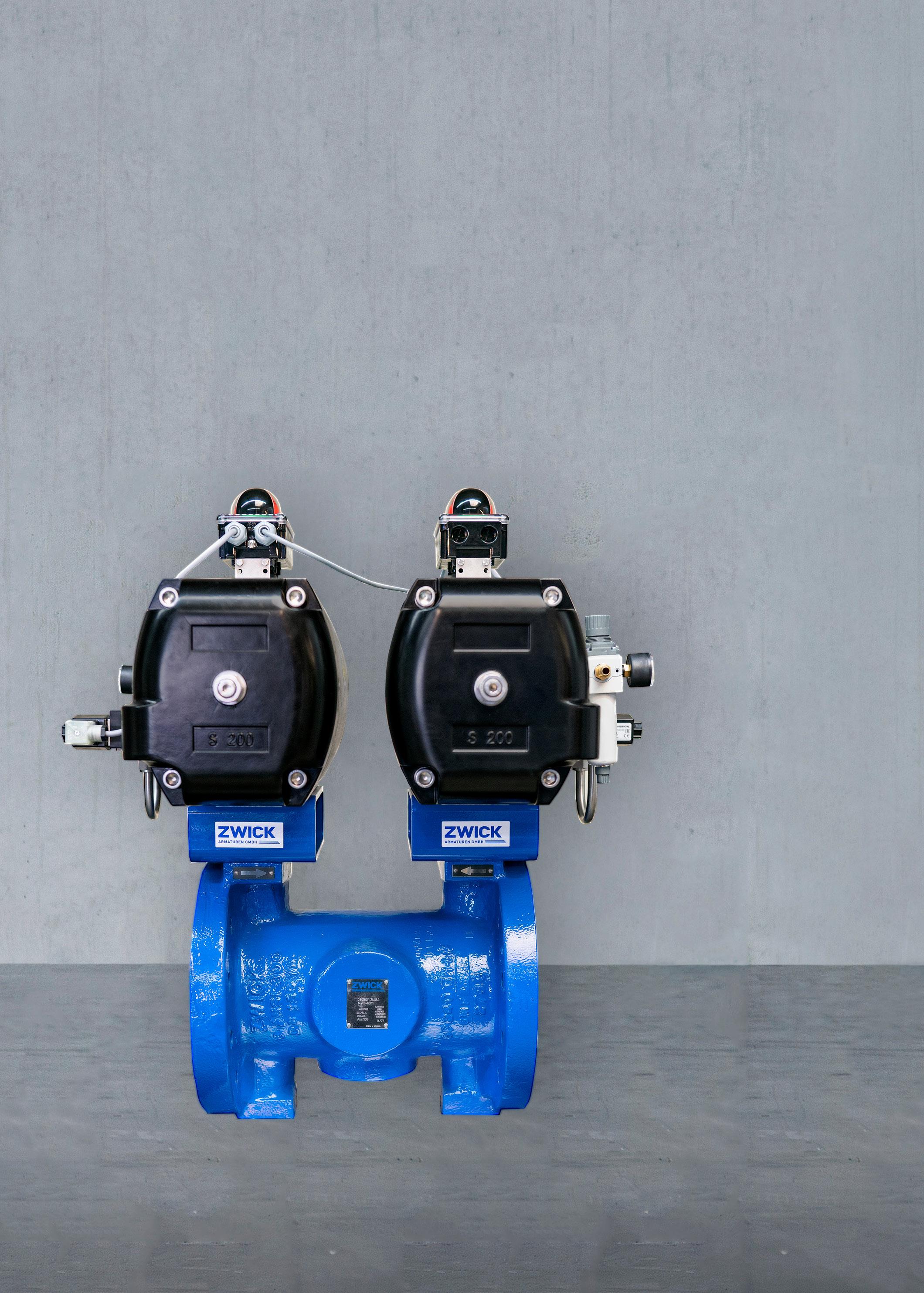
your cryogenic systems with our ASME approved safety relief valves, engineered for reliability when it matters most. Our solutions put safety in the forefront, allowing you to operate with confidence and give you peace of mind.
Ruzbeh Homji, CEO, and Mark Weatherwax, Chief Product Officer, Mechademy, Inc., discuss the design, operation, and monitoring processes for the sustained availability of cryogenic rotating equipment in LNG plants.
Cryogenic rotating equipment plays a disproportionately critical role in the availability of LNG facilities. Cryogenic centrifugal pumps and liquid expanders are often single-point constraints
whose unexpected downtime can directly limit production, delay cargo loading, or extend plant restart timelines, despite representing a relatively small fraction of the installed rotating equipment.
Cryogenic centrifugal pumps are commonly used for LNG rundown, storage tank transfer, and export loading. In many designs, a single operating pump supports a full production train, with limited or no installed spare capacity. Liquid expanders are used in end-flash services, heavies removal systems, and other pressure letdown applications where a Joule-Thomson (JT) valve could otherwise be employed. These expanders are typically unspared, and in facilities where they are tightly
integrated into cold-box operation, a trip can propagate rapidly into throughput loss or unstable operation.
The cost of unplanned outages associated with cryogenic rotating equipment extends beyond lost production. Restarting cryogenic systems often requires controlled warm-up, nitrogen purging, and re-cooldown, increasing both operational complexity and commercial impact relative to comparable ambient-temperature equipment. Sustained availability of cryogenic pumps and liquid expanders, therefore, remains a key reliability objective.
Typical designs and applications
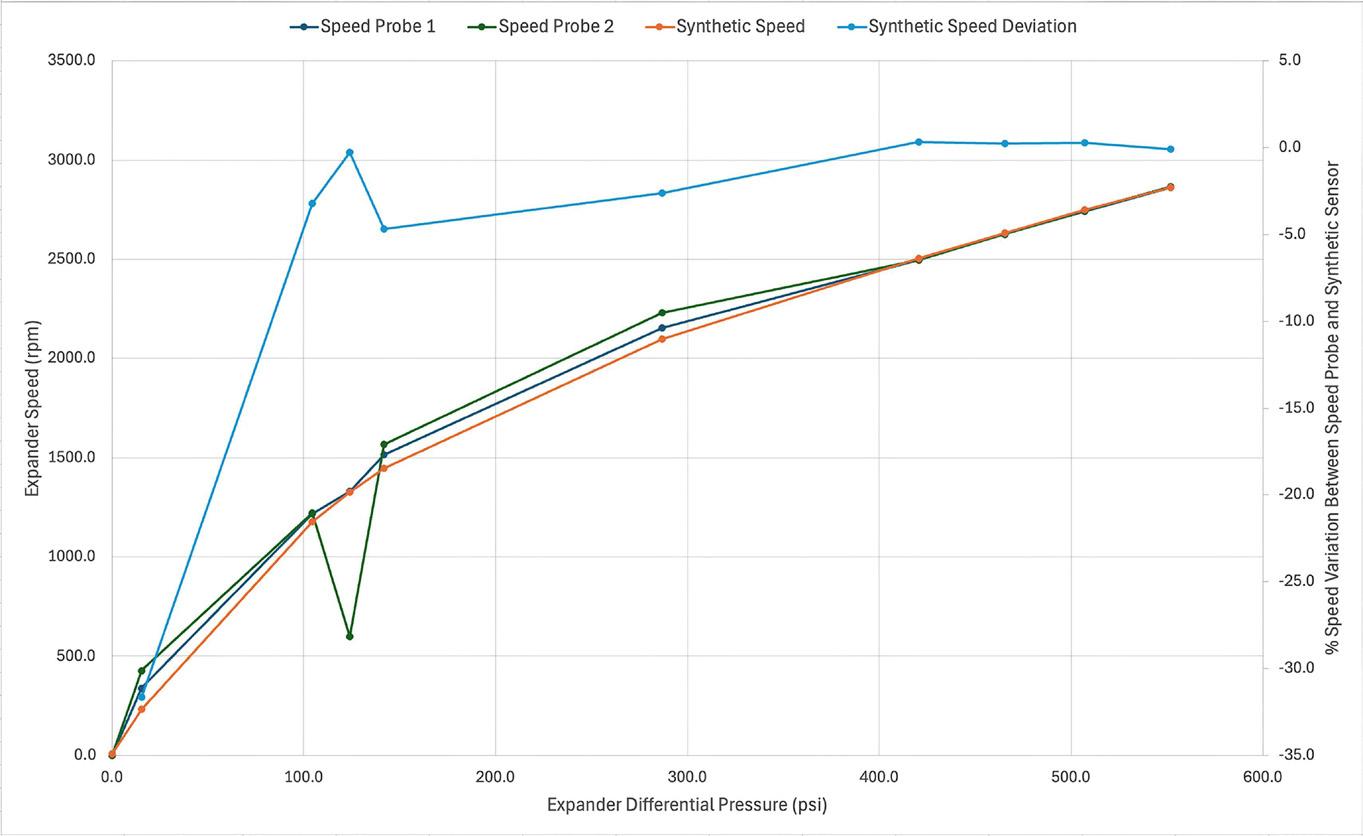
1. A liquid container start-up showing installed speed probes vs a synthetic speed derived from differential pressure. At speeds close to synchronous speed, the synthetic speed sensor is within 0.5% of the actual speed and is not prone to speed dropouts as seen on speed probe 2.
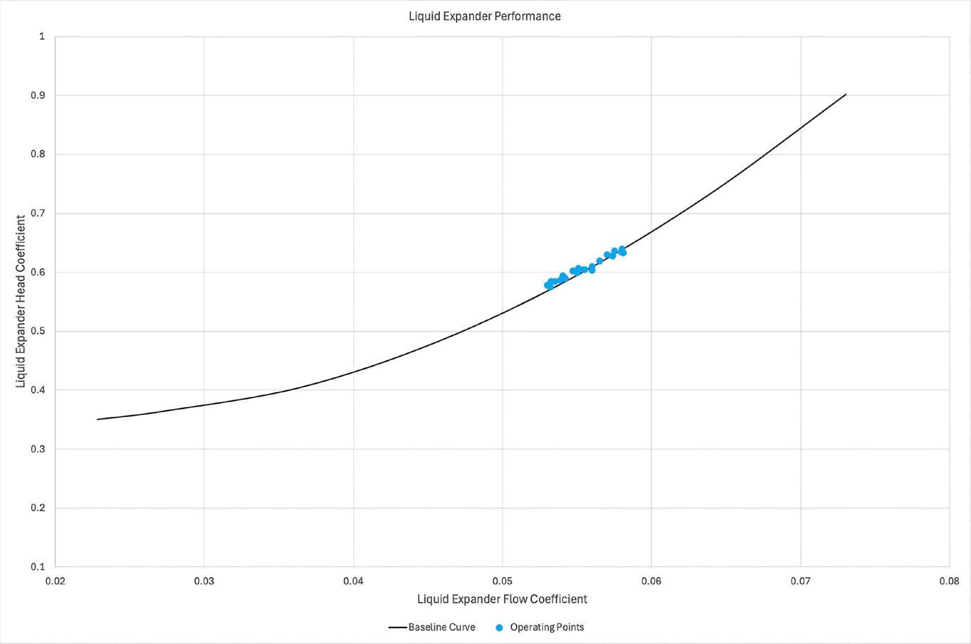
2. Liquid expander operating head co-efficient and flow co-efficient overlayed on the as-tested performance curve.
Cryogenic centrifugal pumps
Cryogenic centrifugal pumps used in LNG plants generally fall into two broad categories: in-tank vertical pumps and pot-mounted vertical pumps.
In-tank pumps are installed within dedicated pump columns inside LNG storage tanks and are commonly used for transfer, circulation, and export loading. The pump and motor are typically submerged in LNG, with product-lubricated bearings and limited maintenance access. These pumps are designed to be removable without draining the tank; when the pump is lifted, an integral valve seat (suction foot valve) at the base of the column closes, preventing further liquid from entering the pump column.
Pot-mounted pumps are installed in external vessels connected to LNG storage or process systems. These arrangements are commonly used for LNG rundown, export, or process transfer duties. While pot-mounted designs allow easier access for maintenance compared with in-tank pumps, they introduce greater sensitivity to suction conditions, liquid level management, and transient operation.
Liquid expanders
Liquid expanders, sometimes referred to as hydraulic turbines, are used in LNG
Figure
Figure
plants to recover energy from pressure letdown of cryogenic liquids. They reduce the enthalpy of the liquefied fluid, enabling increased LNG production while recovering energy.
These machines are typically installed with a bypass JT valve to allow continued operation during start-up, turndown, or expander unavailability. While this bypass capability can reduce the immediate production impact of an expander trip, the resulting changes in refrigeration balance, phase behaviour, or downstream conditions impose operational and production constraints.
Liquid expanders can be fixed-speed or variable-speed and are usually integral with the induction generators, with the complete assembly submerged in cryogenic liquid. Alternative expander designs with external bearings and sealing systems exist but are not considered within the scope of this article.
Engineering and operational considerations for reliable cryogenic rotating equipment
The long-term reliability of cryogenic centrifugal pumps and liquid expanders is governed by the interaction of mechanical design choices, process integration, and operational practices. Although these machines are designed to meet defined duty points, many degradation mechanisms observed in LNG service arise when actual operating conditions deviate from the assumptions made during design. A clear understanding of bearing behaviour, rotordynamics, hydraulics, controls, and instrumentation is therefore essential for sustained availability.
Bearing reliability and thrust management
Bearings remain one of the most frequent sources of reliability issues in cryogenic rotating equipment. These machines rely on the process fluid for cooling and lubrication, making bearing performance sensitive to fluid cleanliness, phase stability, and transient operating conditions. Early designs using conventional metallic rolling elements experienced failures related to material instability, contamination, and electrical arcing. Most modern designs now incorporate stainless steel races with ceramic rolling elements, which offer improved fatigue resistance under marginal lubrication conditions and eliminate susceptibility to electrical discharge damage.
During normal operation, bearings are intended to operate without sustained thrust loading. To achieve this, manufacturers incorporate balance drums or other thrust equalisation mechanisms that rely on stable hydraulic conditions. Deviations from the expected operating envelope, particularly during start-up, shutdown, or abrupt flow changes, can temporarily overcome these balancing features and impose thrust loads on the bearings. Repeated exposure to such conditions can lead to progressive bearing distress, even when steady-state operation appears acceptable.
Rotordynamic design considerations
Most cryogenic pumps and liquid expanders used in LNG service are designed as stiff shaft machines, meaning their first lateral critical speed lies well above the normal operating speed range. This philosophy minimises shaft deflection, reduces sensitivity to imbalance, and limits rotor response to hydraulic disturbances; an important consideration given the small bearing clearances and stability requirements inherent to cryogenic service.
For liquid expanders, rotordynamic evaluations must extend beyond normal operating speed to include runaway speed conditions. Runaway speed refers to the rotational speed an expander can reach if load is lost, such as during loss of electrical load. Under these conditions, the available pressure energy in the liquid is converted directly into rotational energy, allowing the rotor to accelerate until frictional forces balance the developed turbine power.
Hydraulic design, NPSH, and phase stability
Hydraulic considerations are central to the reliability of cryogenic pumps and liquid expanders. For pumps, adequate net positive suction head (NPSH) margin is a recurring challenge that, if not properly addressed, can lead to cavitation damage. Datasheet values are typically based on idealised steady-state conditions, whereas actual LNG operations involve fluctuating tank levels, variable vapour pressures, and frequent transients.
For pumps, NPSH required (NPSHr) is commonly defined at a 3% head drop, a condition under which cavitation and flashing are already present. In cryogenic service, where vapour pressure is extremely low, NPSH margins are inherently tight. Although inducers are used to reduce NPSHr, operating away from the best efficiency point increases NPSH demand and must be accounted for when defining the acceptable operating envelope. For in-tank pumps, extended operation at pump-down levels, where NPSHr may be defined at a higher head drop, such as 10%, can accelerate bearing wear.
Liquid expanders face analogous challenges related to phase stability. Discharge conditions must be carefully controlled to avoid flashing, which can impose fluctuating hydraulic loads and disrupt cooling of bearings and generators. Some supplier designs permit a limited fraction of continuous flashing at the expander outlet; however, vapour formation in close proximity to bearings or electrical components presents a significant risk.
In addition to hydraulic design margins, cleanliness during commissioning and maintenance has a direct impact on reliability. Contaminants such as heavier hydrocarbons, or residual moisture can accumulate and freeze at cryogenic temperatures. This material may block strainers, restrict flow paths, or introduce localised pressure losses, leading to unstable operation, cavitation, or inadequate cooling of bearings and electrical components.
Controls, sequencing, and transient operation
Control strategies and sequencing logic play a decisive role in protecting cryogenic rotating equipment.
For pumps, minimum-flow recirculation systems must be correctly sized and sequenced to prevent operation at low flows while avoiding abrupt hydraulic disturbances. Aggressive opening of minimum-flow valves has been associated with transient thrust reversals, momentarily overloading thrust balancing devices and bearings. For liquid expanders, the interaction between the expander and the bypass JT valve is particularly critical. Controlled transfer of flow between these elements is necessary to maintain process stability and prevent production loss. Start-up valves and speed-control logic must ensure smooth acceleration through speed ranges where thrust equalisation mechanisms become effective. Expander operation at low rotational speeds, either before or after synchronisation to the electrical grid, must be minimised to prevent bearing damage due to prolonged thrust loading.
Soft stops, in which process flow is ramped down in a controlled manner prior to shutdown, are especially important for extending expander life, and careful attention should be paid during the engineering phase to define which fault conditions truly require immediate hard trips.
Mechanical, electrical, and installation considerations
Thermal transients are an unavoidable aspect of cryogenic service. Rapid temperature changes during cool-down, warm-up, or upset recovery can induce differential contraction, misalignment, and stress within shafts, bearings, and casings. During initial cool-down, in particular, thermal shock can result in shaft deformation and impeller damage. Controlled ramp rates are therefore essential, even when operational pressures favour faster transitions.
Mechanical and electrical details that may appear secondary can have outsized reliability impacts. Undersized electrical lugs on in-tank pumps have been associated with repeated failures requiring frequent repair. Similarly, insufficient foundation stiffness or exposure to ambient vibration from nearby equipment can lead to bearing brinelling during extended shutdowns. These issues often manifest long after installation, underscoring the importance of early design review and installation quality.
Instrumentation limitations and design implications
Instrumentation in cryogenic service presents challenges distinct from those in most other machinery. Rotational speed sensors are commonly installed directly in cryogenic liquid and have demonstrated reduced reliability. Because accurate speed measurement is essential prior to synchronisation with the electrical grid, some operators have implemented synthetic speed indicators based on the relationship between expander differential pressure and rotational speed. When properly validated, these synthetic sensors can serve as reliable backups to primary speed sensors during start-ups (Figure 1).
Vibration monitoring philosophies must also be adapted. Cryogenic pumps and liquid expanders are
typically fitted with casing-mounted accelerometers. The damping effect of the cryogenic fluid and the inherent stiffness of the casings result in vibration amplitudes that are significantly lower than those observed in non-cryogenic centrifugal pumps. Effective interpretation, therefore, relies less on absolute vibration levels and more on a contextual understanding of operating conditions.
Monitoring and diagnostics best practices
Effective monitoring of cryogenic rotating equipment requires a balanced approach that distinguishes between protection, condition assessment, and performance evaluation.
Protection systems, such as trips and permissives, are essential for preventing catastrophic damage but are reactive. These systems are designed to respond once predefined limits are exceeded; therefore, they provide limited insight into gradual degradation. Predictive monitoring aims to detect early signs of mechanical or hydraulic distress before protective thresholds are reached. Performance monitoring focuses on deviations from expected hydraulic or thermodynamic behaviour that may indicate developing issues (Figure 2).
Because of the aluminium impellers and static parts within pumps and liquid expanders, failed bearings can destroy the internals of these machines, resulting in significantly longer downtime than simply replacing bearings and wear parts. Methodologies such as vibration prediction using multivariate machine learning models and motor electrical signature analysis have proven effective for early detection of faults, including bearing damage, structural resonance, piping resonance, and premature wear on bushings and wear rings.
Advanced analytics, including univariate and multivariate anomaly detection, are increasingly applied to cryogenic rotating equipment. These techniques can identify subtle changes in behaviour that precede failures, but they must be grounded in mechanical and process plausibility to avoid false positives.
The most effective monitoring strategies integrate multiple data sources and algorithms, and emphasise domain-driven, multi-sensor diagnostics over static alarm thresholds and anomaly detection.
Conclusion
Cryogenic centrifugal pumps and liquid expanders occupy a critical position in LNG plant operations, where their availability directly influences production and operational flexibility. Although these machines are designed for demanding service, long-term reliability depends on how effectively they are integrated into the process, managed during transient operation, and monitored over time. Industry experience demonstrates that many failures are preventable through realistic operating assumptions, disciplined control strategies, and integrated monitoring approaches that align design intent with operational reality.
For shipowners, the energy transition is shaped not only by fuel selection, but by operational reliability, risk exposure, and total cost of ownership. Rasmus Gregersen, Svanehøj, Denmark, looks at some low and high-pressure pump solutions that support today’s LNG applications while providing flexibility in an evolving fuel landscape.
Marine pumps have always been essential to ship operations. But, in the context of the energy transition, pump technology has assumed a more central, mission-critical role within the vessel’s fuel supply system.
As maritime fuels diversify and regulatory requirements become more stringent, fuel pump performance has become a critical factor for safety, efficiency, compliance, and commercial viability.
Innovation in marine fuel pumps is closely tied to the energy transition in shipping. Shipowners are seeking solutions that enable the use of alternative fuels and lower emissions without compromising uptime, operational reliability, or vessel lifetime economics.
Redefined requirements for critical marine equipment
Consequently, the energy transition is translating into more stringent and clearly defined requirements that suppliers of critical equipment must address in their product innovation.
Reliability and uptime
Alternative fuels such as LNG, methanol, and ammonia rely on highly integrated fuel systems with strict safety requirements and limited tolerance for failure. As a result, shipowners require robust designs with fewer failure points and stable performance under demanding
operating conditions. In this context, innovation lies in engineering simplicity, robustness, and operational reliability.
Operational efficiency
Energy efficiency remains a commercial and regulatory consideration. However, in complex fuel systems, forced fuel changeovers, operational disturbances, or unplanned downtime can quickly outweigh marginal efficiency gains. For shipowners, operational efficiency therefore means predictable performance, protecting schedule integrity, and avoiding costly deviations from the intended fuel strategy.
Fuel adaptability
While most shipowners currently invest in clearly defined fuel strategies, a growing segment is considering how to maintain flexibility in an evolving fuel landscape. For these operators, avoiding overly rigid, single-fuel solutions is part of protecting long-term asset value. Such considerations place requirements on materials, sealing technologies, and overall system design capable of handling cryogenic temperatures, varying chemical properties, and changing lubrication characteristics as fuel pathways develop.
Reduced maintenance and longer service intervals
Lower maintenance requirements are increasingly seen as a core value proposition among shipowners. Predictable wear patterns, extended service intervals, and maintenance without tank access reduce risk, support compliance with safety procedures, and enable more efficient lifecycle maintenance planning.
Total cost of ownership
Procurement decisions are shifting from upfront cost to lifecycle value. Shipowners evaluate energy consumption over the pump’s lifetime, service and spare parts costs, uptime and operational reliability, and risk exposure linked to failures or inefficiencies. As a result, innovation in marine pumps must be supported by clear documentation of long-term value, not just technical performance data.
Documentation, compliance, and transparency
Regulatory requirements are playing an increasingly central role in equipment selection. Shipowners expect suppliers to provide reliable performance documentation, support compliance reporting, and contribute to ESG and emissions accounting. Pump suppliers are therefore becoming partners in compliance, not just equipment manufacturers.
LNG is the dominant alternative fuel type
When shipowners assess alternative fuel options, the availability of refuelling infrastructure is a critical factor. Understanding when and where vessels can refuel is essential for operational planning, route flexibility, and long-term investment decisions. In this context, dual-fuel LNG has emerged as a widely-adopted solution.
According to DNV’s Alternative Fuels database, LNG stands out as the dominant alternative fuel, leading the 2025 global orderbook across vessel segments and representing 31% of total gross. In total, 846 LNG-fuelled ships were in operation by the end of 2025, while 642 were on order. Over the past three years, the number of LNG-powered vessels in operation has increased by almost 140%, while an already substantial global orderbook has expanded by close to 25%. The broader global market further illustrates LNG’s position, with methanol accounting for 103 vessels in operation and 344 on order, while ammonia remains at an early stage with three ships in operation and 46 on order.
While circumstances may change in the future, LNG today offers comparatively broad global bunkering availability, established handling procedures, and a mature regulatory framework, allowing shipowners to reduce emissions while maintaining operational flexibility. The dual-fuel configuration further mitigates risk by enabling vessels to switch between LNG and conventional fuels, reducing exposure to fuel availability constraints and infrastructure gaps during the transition phase. To manage long-term uncertainty, many shipowners are pairing dual-fuel LNG vessels with ammonia-ready designs, enabling conversion or upgrading as alternative-fuel pathways and infrastructure mature.
Deepwell or submerged: Vessel type defines the selection
In LNG fuel gas supply systems, the initial low-pressure fuel supply from the tank is provided by either a submerged or a deepwell cryogenic pump. Both are electrically driven but differ fundamentally in their motor arrangements and mechanical configurations. The submerged pump integrates the motor inside the tank, whereas the long-shafted deepwell pump is driven by a deck-mounted motor.
The selection between the two configurations is closely linked to vessel type and operational profile. Submerged pumps emphasise compactness and are typically favoured for smaller vessels, ferries, offshore support vessels, and short-sea operators where space constraints are decisive.
Deepwell pumps, by contrast, separate electrical drive components from the cryogenic zone and are engineered for controlled shaft dynamics and long-term mechanical stability. They are typically specified for large ocean-going vessels, including container ships, car carriers, and tankers, where extended mean time between repair (MTBR) and high operational reliability are prioritised.
In 2016, Svanehøj introduced the market’s first deepwell fuel pump, specifically designed for LNG fuel gas supply systems, leveraging proven cargo pump technology for the fuel segment. Since then, more than 1500 Svanehøj DW Fuel Pumps have been delivered worldwide for low-pressure fuel gas applications.
While the deepwell configuration entails a higher upfront investment than submerged alternatives, it offers distinct operational advantages in cryogenic environments. With the motor installed on deck, sensitive electrical components are kept
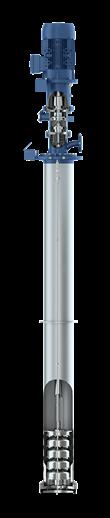
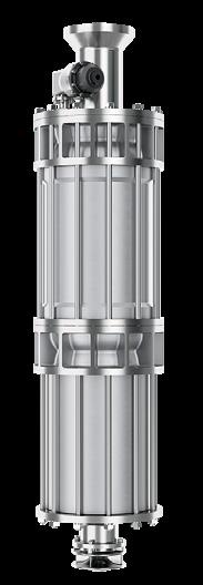
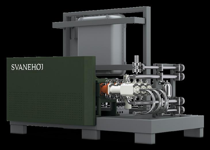
Figure 1. Svanehøj DW Fuel Pump (left); Svanehøj CS Fuel Pump (middle); and Svanehøj HPP Triplex Unit (right).
Powering your vessel with a fuel pump you can trust
At Svanehoj, we understand your challenges and that results count. That is why, we take pride in delivering trusted solutions and being a partner you can rely on every step of the way.
With a wide range of pump models in our portfolio, we deliver the right pump for every fuel type — offering dependable solutions that meet both system requirements and end‑user expectations.
Fuel pump solutions built on deep expertise - keeping your operations safe, reliable and future-proof.
outside the cryogenic tank environment, avoiding direct exposure to LNG temperatures and limiting thermal influence on the tank. Together, these attributes enhance operational reliability, simplify maintenance, and support predictable lifecycle performance, which are critical factors in large, asset-intensive fleets. As a result, deepwell pumps have gained significant traction among container ships, car carriers, and other large ocean-going vessels operating on fixed schedules with minimal operational margins. For these vessels, ensuring an uninterrupted LNG supply and avoiding forced changeover to conventional fuels is critical.
Fuel pumps built for today’s maritime operations and tomorrow’s demands
Keeping LNG in its liquid form requires cryogenic conditions of at least -162˚C (or a built-up relative pressure). LNG pumps must therefore be highly reliable, durable, and constructed from materials that function optimally under cryogenic conditions. Since the early 2010s, Svanehøj has focused on developing fuel pumps and system components for LNG and other alternative fuels with an emphasis on extended MTBR. This engineering philosophy is reflected across the DW Fuel Pump, the Cryogenic Submerged (CS) Fuel Pump, and the High-Pressure Pump (HPP) Triplex Unit, which all incorporate patented design features that minimise tank intervention, simplify maintenance, and support stable, long-term operation.
The Svanehøj DW Fuel Pump is a classic multistage centrifugal pump made of cryogenic stainless steel. It incorporates a patented static seal and a patented foot valve system. The static seal isolates the pump from the tank when activated, allowing the inner magnetic coupling, the main pump bearing, and the oil filter to be accessed, dismantled, serviced, or replaced without removing the pump from the tank. The foot valve system further enhances service flexibility by enabling the pump to be extracted and a complete overhaul to be performed regardless of tank content or liquid level. For many operators, this capability is a decisive advantage, as it allows maintenance to be performed immediately without the need to gas-free the tank. Extensive validation testing and lifetime analysis of critical mechanical components confirm a design service interval of five years or 25 000 operating hours. Furthermore, all scheduled maintenance up to 10 years or 50 000 operating hours can be completed without tank entry.
The Svanehøj CS Fuel Pump is a centrifugal pump with a standardised shaft design, engineered to operate reliably in
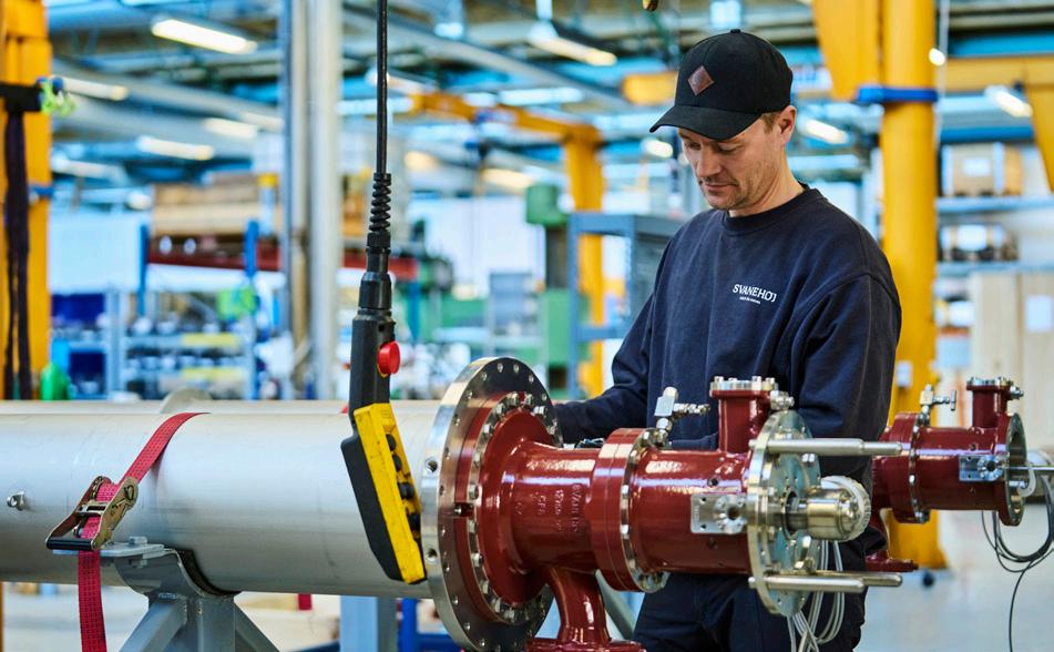
cryogenic temperatures. It incorporates a patented, self-cleaning LNG filter and an interior permanent magnet (IPM) motor. The self-cleaning LNG filter is a side-flow filter that separates harmful particles from the LNG stream while generating a controlled secondary flow to support motor cooling and bearing lubrication. The design ensures stable filtration performance with minimal pressure differential and provides easy access for inspection or replacement. The IPM motor is designed to operate fully submerged under cryogenic conditions with an efficiency of up to 96.8%, significantly exceeding the typical industry range of 84 – 88% for conventional induction motors. The high efficiency ensures that a greater proportion of electrical energy is converted into mechanical output, reducing internal heat generation and thereby minimising the risk of boil-off gas formation. Extensive validation testing and lifetime analysis of critical mechanical components demonstrate a service interval of 20 000 operating hours, exceeding the typical industry benchmark of 16 000 hours.
The Svanehøj HPP Triplex Unit is a compact high-pressure LNG fuel pump solution developed specifically for the maritime industry. Designed for operating pressures of 380 – 420 bar, the unit features a belt-drive system and three combined cold ends. It incorporates a patented active sealing system and a patented valve design. The active sealing system combines lubrication and gas containment by maintaining a controlled differential pressure across an oil-filled chamber, ensuring stable sealing performance under high-pressure conditions and extending MTBR. The inlet valve reduces cavitation risk by increasing the effective intake area, minimising pressure losses, lowering the required inlet pressure, and improving filling of the compression chamber, resulting in more stable and efficient high-pressure operation. Based on extensive validation testing and lifetime analysis of critical mechanical components, a service interval of approximately 6000 operating hours is expected for the HPP Triplex Unit.
A critical enabler in the energy transition
As LNG propulsion continues to expand across deep-sea segments, fuel pump technology is increasingly decisive for vessel reliability, emissions performance, and lifecycle economics. The shift towards high-pressure fuel systems, combined with stricter uptime expectations and regulatory compliance, has elevated pump design from a supporting component to a critical enabler of safe and stable fuel operations.
In a market defined by technical complexity and long-term investment decisions, shipowners are not only selecting fuels; they are selecting system robustness. As alternative fuel pathways continue to evolve, the technical demands placed on fuel supply systems will only increase.
Svanehøj has positioned itself to support this development through sustained investment in engineering and product innovation. As part of its ESG strategy, the company allocates at least 95% of its R&D investments to technologies and solutions that support the energy transition. This includes the continued advancement of low-pressure and high-pressure pump solutions designed to meet rising requirements for durability, efficiency, safety, and extended MTBR.
In an energy landscape defined by uncertainty and tightening regulation, proven system architecture and ongoing technical refinement are becoming decisive factors for commercially viable propulsion.
Figure 2. Svanehøj’s pump programme includes a range of pumps for various applications in the marine industry. The deepwell design was developed in the 1960s and has been the cornerstone in developing pumping solutions for the safe handling of LNG and other complicated fluids.
Mike Wells, Nikkiso Clean Energy & Industrial Gases Group, USA, considers the opportunity to reduce emissions from vessels by increasing the pressure of fuel gas supply systems.
The marine sector has been committed to reducing its carbon emissions and playing its part in the journey to net zero for many years. Today, that long-standing commitment is gathering real momentum, as regulatory pressure and technological maturity turn ambition into action across the global fleet.
Much of this shift can be traced back to the International Maritime Organization’s (IMO) decarbonisation commitments outlined in 2023. These measures underpin the IMO’s response to UN Sustainable Development Goal 13 – urgent action to combat climate change – and have become a key catalyst for the changes now reshaping marine propulsion and fuelling strategies.
Against this backdrop, the limitations of traditional propulsion systems are becoming increasingly apparent. For decades, most commercial marine vessels have relied on petroleum-based fuels such as heavy fuel oil (HFO). However, as the global shipping industry accelerates towards decarbonisation and tighter emissions standards, the demand for alternative fuel sources capable of delivering meaningful carbon reductions is rising.
LNG as a marine fuel
Among those alternatives, LNG has been used as an alternative fuel to HFO and marine diesel oil on board ships for decades. Since the early 1960s, LNG has been used
extensively aboard LNG carriers, where natural boil-off from atmospheric cargo tanks is utilised to meet propulsion and electrical powering demands. This approach not only improves operational efficiency, but also significantly reduces emissions compared with conventional heavy fuel oil and diesel.
What was once a niche solution has now become a mainstream option. Since 2008, global shipping emissions regulations have become progressively tighter with reduction targets introduced for sulfur oxide and nitrogen oxide and, more recently, carbon dioxide. These targets set by the EU Emissions Trading System and FuelEU Maritime, alongside the IMO, are designed to achieve net-zero greenhouse gas emissions by 2050. As a result, LNG has emerged as the most attractive fuel option for a wide range of vessel types and sizes, accelerating demand for efficient and robust fuel gas supply systems (FGSS).
A typical FGSS is designed to transfer the LNG stored in a cryogenic containment tank (whether pressurised or atmospheric) at the required temperature and pressure conditions to the ship’s main consumers, such as the main propulsion engine and the generating sets which can be either two-stroke low-pressure, two-stroke high-pressure, and/or four-stroke low-pressure systems, and the boilers.
The importance of the FGSS
Within these systems, the most critical and technically demanding component is the pumping unit. In high-pressure FGSS configurations, the pumping unit provides the main propulsion power of the ship at delivery pressure of up to 385 bar. Cryogenic reciprocating piston pumps have proven to be the most efficient method and reliable solution for meeting these demanding operating conditions.
Each FGSS consists of a set of redundant reciprocating piston pumps that are directly driven by electric motors through a gearbox or a belt drive, and supported by a dedicated lubrication system supplying oil to the warm ends (Crankcases) of the pumps. All the necessary controls, piping, valves, safety devices, and instrumentation are mounted on a common structural steel base or skid, providing a modular turn-key solution for integration aboard vessels.
At the heart of the FGSS are the cryogenic reciprocating pumps. The cryogenic reciprocating pump consists of a ‘warm end’ or drive assembly that converts rotary motion from the electric motors into reciprocating motion, and a ‘cold end’ where the cryogenic liquid is pressurised from low pressure
to high pressure. The warm end is of a modular design that lets the pump be configured with the optimum number of cold ends for a given application. An intermediate housing connects and thermally isolates the warm end housing from each cold end cylinder housing, protecting mechanical components in the warm end from extreme cold temperatures. The warm end components (bearings, crosshead, and wrist pin) are pressure-lubricated by an external oil lubrication system to ensure reliability during continuous operation. The cold ends use specialised cryogenic piston seals to pressurise the fluid and minimise boil-off gas generation.
The challenge and opportunity of increasing pressure
As propulsion technologies continue to develop in response to tightening emissions regulations, the utilisation of higher LNG and ethane fuel pressures have been found to enable more efficient engines, directly translating into reductions in carbon emissions. As a result, recent research and innovation has focused on developing engines and fuel systems capable of operating at 380 bar, 420 bar, and beyond.
As marine engine injection pressures increase, the design and manufacture of high-pressure FGSS introduce a series of complex technical challenges. Operating at pressures of 380 bar and above increases mechanical loads on pumping components, intensifies sealing and efficiency requirements, and places greater emphasis on material selection, particularly for wearing components such as bearings, piston seals, and packing seals, as well as system components such as valves, flanges, and instrumentation.
Sustained high-pressure operation requires careful optimisation of pump hydraulics, tight manufacturing tolerances, and effective thermal separation between warm-end drive assemblies and cryogenic cold-end components. At elevated pressures, minor deviations in alignment can have a disproportionate impact on reliability and service life.
Operational experience from high-pressure FGSS systems deployed in LNG vessels has highlighted the importance of long-duration service data in validating design assumptions. Extended operating experience at pressures exceeding 380 bar, and in some applications approaching 500 bar, has provided valuable insight into wear behaviour, sealing performance, lubrication regimes, and maintenance requirements. These findings continue to inform the evolution of FGSS designs as the marine sector moves towards higher-efficiency engines and a broader mix of low-carbon and alternative fuels.
Supporting shipyards through the standardisation of FGSS systems is critical as emissions requirements become more stringent year over year, allowing a single design rated for up to 500 bar to be utilised repeatedly well through the next 10 years of shipbuilding. This reduces the risk of needing to redesign fuel preparation spaces on vessels as fuel pressure requirements potentially continue to rise.
As emissions regulations increasingly require operators to meet average performance targets across their fleets, older vessels will continue to be phased out and replaced by ships fuelled by alternative fuels or higher-pressure engines. In this evolving regulatory and technological landscape, flexibility is critical.
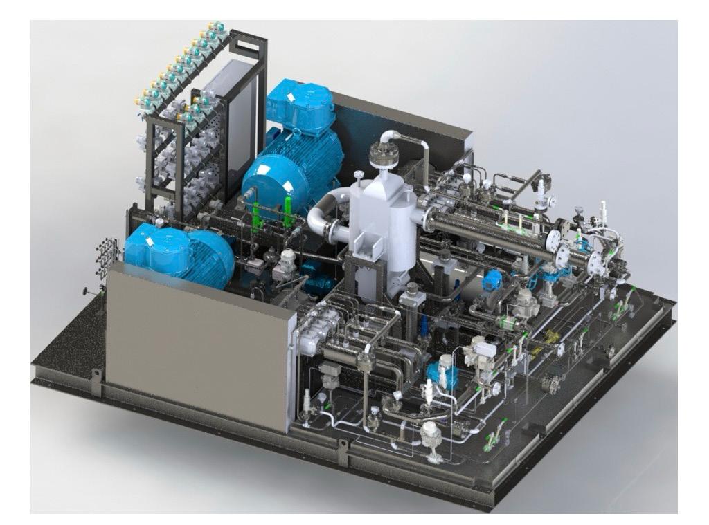
Figure 1. Fuel gas supply skid with two reciprocating pumps.
Karl Aerts, Martin van Burgh, and Hans-Peter Visser, Analytical Solutions and Products BV, showcase modern total mass balancing systems for FSRUs.
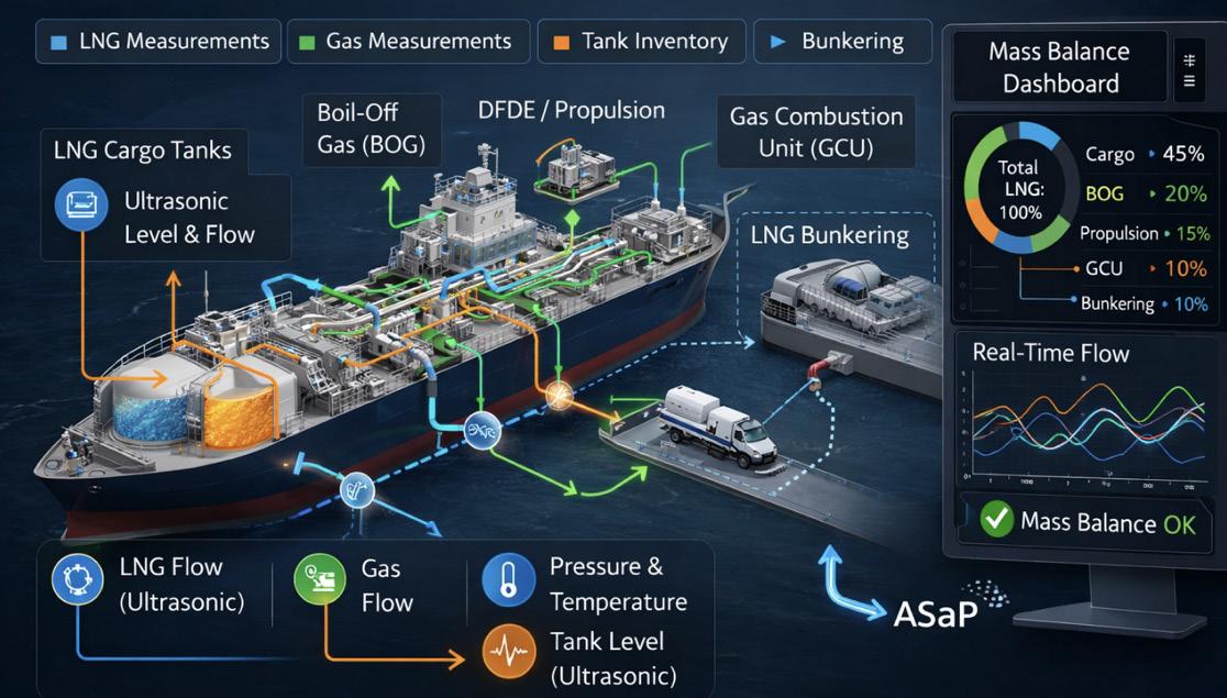
An FSRU functions as a floating LNG import terminal. After an LNG carrier moors alongside, the LNG is transferred into the FSRU’s cargo tanks. From there, the LNG is routed forward, regasified on board, and delivered as high pressure natural gas through the export metering system to the onshore end user(s).
The energy quantity transferred (expressed in million Btu), forms the basis for commercial settlement between the LNG seller, the LNG buyer, and the FSRU operator. The methodology for determining this billable energy is defined in the sales and purchase agreement (SPA), which follows the guidelines established by the Groupe International des Importateurs de Gaz Naturel Liquéfié (G.I.I.G.N.L.).
Transferring energy
When examining an FRSU in more detail, the following primary process streams can be identified:
1. Incoming LNG: LNG transferred from the LNG carrier into the FSRU’s cargo tanks.
2. Boil-off gas (BOG) to LNG carrier: Excess vapour returned to the LNG carrier to maintain pressure balance during unloading.
3. Gas streams to dual fuel diesel electric (DFDE) engines: Natural gas supplied as fuel for vessel propulsion and power generation.
4. Gas stream to the gas combustion unit (GCU): Surplus BOG routed to the GCU for safe disposal when it cannot be used or returned.
5. High pressure gas export to shore: Regasified LNG sent through the metering system and exported as high pressure natural gas to the onshore pipeline network.
Incoming LNG
In LNG custody transfer operations, product quality is determined using representative samples taken from the two crossover manifolds on deck, before the LNG enters the storage tanks. The industry standard approach uses a Phazer system – an integrated sampling probe and vaporiser installed directly on the LNG transfer line.
The Phazer extracts LNG, vaporises it in a controlled manner, and delivers a homogeneous gas sample to two parallel measurement systems:
z An intermittent LNG sampler for physical sampling.
z An online process gas chromatograph (PGC) for continuous composition and energy-content analysis.
The quantity of LNG transferred is typically established using tank gauging, though the use of flow meters for dynamic measurement is increasingly common across modern FSRUs and shore-based terminals.
BOG return energy determination in LNG custody transfer
As part of LNG custody transfer, the energy associated with BOG returned from an FSRU to an LNG carrier during unloading must be accurately quantified. This returned vapour represents a measurable energy stream and therefore directly affects the commercial balance between the parties. The energy content of the BOG is determined by:
z Measuring the volumetric flow rate of the returned gas.
z Recording its pressure and temperature.
z Conducting a compositional analysis to determine the gas’ heating value.
These parameters are combined to calculate the total energy of the BOG using standardised LNG custody transfer methods, ensuring fair and transparent accounting between the FSRU operator, LNG seller, and buyer.
Gas streams to DFDE engines
This stream supports both allocation and engine control functions. Each DFDE engine receives its own dedicated gas
supply line, where key operating parameters – including flow rate, pressure, temperature, and gas composition – are continuously measured. These measurements serve two primary purposes:
1. Mass and energy balancing: The gas composition, combined with flow and thermodynamic data, is used to determine the heating value of the fuel gas supplied to each engine. This supports accurate allocation, performance tracking, and overall mass balance reconciliation on the FSRU.
2. Combustion optimisation: The compositional analysis is used to calculate the methane number, an essential indicator for engine knock resistance. Maintaining the methane number within the optimal range ensures stable combustion, protects the engine against knocking, and optimises efficiency and emissions performance.
Gas stream to GCU
The measurement application for the gas stream routed to the GCU is essentially identical to that used for the DFDE engine fuel gas streams. Flow, pressure, temperature, and gas composition are continuously monitored to determine the heating value for accurate mass and energy balancing.
As with the DFDE engine streams, the compositional analysis ensures the gas characteristics are well understood; however, in the GCU’s case, the primary objective is operational safety and controlled disposal of surplus BOG rather than combustion optimisation. The measurement ensures that the GCU receives a correctly characterised gas stream, supporting reliable operation and compliance with custody transfer and environmental requirements.
The importance of mass and energy balancing in modern LNG operations
As the global LNG fleet expands, the complexity of onboard gas and LNG handling systems increases alongside it. Modern vessels – whether LNG carriers, FSRUs, FLNG units, or other floating storage and production platforms – simultaneously manage multiple critical processes. These include cargo transfer operations, BOG management, propulsion fuel-gas supply, and bunkering activities. Each of these processes relies on accurate, real-time measurement and precise control.
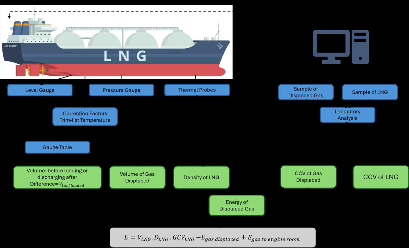
Figure 1. Diagram showing the energy of gas to engine room. E: total net energy transferred in million Btu; VLNG: volume of LNG loaded or unloaded in m3; DLNG: density of LNG loaded or unloaded in kg/m3; GCVLNG: gross calorific value of the LNG loaded or unloaded in million Btu/kg; Egas displaced: net energy of the displaced gas in million Btu; Egas toER: energy of the gas consumed in the LNG carrier’s engine room and gas combustion units (million Btu).
In such an environment, having a clear and comprehensive understanding of how every Btu of LNG and gas is distributed and consumed becomes essential for safe, efficient, and commercially transparent operations. This is where a well-designed mass and energy balancing system delivers significant value.
Instead of depending on isolated measurement systems scattered across various operational domains, a mass balance platform consolidates all relevant data streams into a single, unified, and intuitive visualisation. This integrated approach provides operators with an immediate, vessel-wide overview
of LNG and gas movements, enabling them to quickly verify flow paths, confirm operational integrity, and detect anomalies.
The result is improved decision making, enhanced safety, and more reliable custody transfer and process control performance across the entire vessel.
From fragmented data to operational clarity
Traditionally, LNG vessels rely on numerous independent measurement sources – including LNG flow meters, gas flow meters, tank level instrumentation, online composition analysis and various process sensors. Although each system provides valuable data, they often operate in isolation, making it difficult for operators to gain a clear, real-time understanding of overall LNG and gas behaviour on board.
contact or mechanical wear. This design offers several important advantages in cryogenic LNG environments:
z High measurement accuracy.
A mass and energy balancing system resolves this challenge by consolidating all relevant measurements into a single, integrated monitoring platform. Key operational parameters (such as compositions, flow rates, pressures, temperatures, and tank inventories) are continuously processed, reconciled, and displayed in an intuitive visual environment. With this unified overview, operators can instantly monitor:
z LNG transfers between tanks or process systems.
z BOG generation and handling, including BOG return and consumption.
z Propulsion fuel gas usage, such as DFDE engine consumption.
z Gas directed to the GCU for safe disposal.
z LNG used by auxiliary systems or dedicated fuel supply lines.
This consolidated visibility enables operators to quickly identify discrepancies, unexpected losses, or anomalies in the system. Every LNG and gas flow becomes fully traceable, supporting both operational integrity and commercial accuracy.
In essence, a mass balancing system transforms large volumes of raw measurement data into clear, actionable operational insight, giving crews the clarity needed to run complex LNG operations safely, efficiently, and confidently.
Accurate measurement starts with the right technology
The reliability of any mass balance system depends fundamentally on the quality of its underlying measurements. In LNG applications, this makes the selection of suitable flow measurement technology especially critical.
Across the LNG industry, ultrasonic LNG flow meters have become the predominant choice for many measurement applications. Unlike traditional mechanical meters that rely on moving components, ultrasonic meters operate without physical
z Long-term stability and repeatability.
z Minimal mechanical wear.
z Reduced maintenance and downtime.
Because ultrasonic meters determine flow by measuring the transit time of sound waves through the liquid, they deliver highly-precise flow calculations without introducing mechanical resistance or pressure loss to the system.
Importance for LNG operations
For activities such as custody transfer, fuel accounting, and process monitoring, high accuracy data is essential. Ultrasonic meters provide the reliability needed for these critical operations. Their non-intrusive design also supports long operational lifespans – an important advantage for LNG carriers and facilities operating continuously around the world.
Enhancing mass and energy balance systems
When high performance measurement technologies like ultrasonic flow meters are integrated into a broader mass balance platform, operators gain:
z Improved visibility of system performance.
z Higher confidence in the accuracy of key operational data.
z Reduced measurement uncertainty across the supply chain.
This combination of advanced instrumentation and robust data management creates a stronger foundation for safe, efficient, and transparent LNG operations.
Supporting the rapid growth of LNG bunkering
As LNG continues to gain momentum as a marine fuel, LNG bunkering has emerged as one of the fastest growing
Figure 2. Complete mass balance and measurement overview.
segments in the industry. The expansion of LNG-fuelled vessels, along with tightening global emission regulations, has made accurate and transparent bunkering operations more important than ever.
Ensuring accurate custody transfer
During LNG bunkering, custody transfer accuracy is essential for both the supplier and the receiving vessel. Transparent and verifiable measurements help build trust between parties and ensure that contractual quantities are delivered and documented with confidence. High-quality measurement reduces disputes, supports compliance, and strengthens commercial relationships.
Mass balance as an additional layer of validation
A mass balance system enhances custody transfer reliability by providing an independent validation layer. It compares the measured bunkered LNG quantity against:
z Pre and post-transfer tank inventories.
z Real-time flow meter data.
z Density and energy content calculations.
By integrating bunkering flow meters into a unified mass balance and visualisation platform, operators gain a complete view of the bunkering process from initial tank conditions to final inventory reconciliation.
Improving transparency and simplifying verification
This holistic approach significantly enhances operational transparency. Operators can:
z Monitor all relevant measurement points in real time.
z Detect discrepancies early.
z Streamline post transfer documentation.
z Reduce the administrative burden associated with manual checks.
The result is a faster, more reliable bunkering process, with improved confidence in the delivered quantities for both parties.
A true one-stop shop for LNG measurement systems
Developing an integrated mass balance solution requires expertise spanning instrumentation, flow measurement technologies, data acquisition platforms, and in-depth knowledge of LNG processes. There are few organisations that can deliver all these disciplines under one roof.
Analytical Solutions and Products (ASaP) provides this capability through a comprehensive one-stop shop approach. The company delivers complete LNG measurement and monitoring solutions, covering every stage of the workflow from system engineering and instrumentation to full integration, commissioning, and visualisation.
Integrated components for a complete solution
Typical ASaP systems combine multiple measurement and analytical elements into a unified, high performance platform, including:
z Online compositional analysis.
z Gas flow measurement systems.
z Pressure and temperature instrumentation.
z Data acquisition and control systems.
z Real time visualisation software.
z Advanced mass balance algorithms and reconciliation tools.
By integrating all these components into a single environment, ASaP ensures seamless data accuracy, consistent operation, and optimised system reliability.
Global service for global LNG assets
LNG vessels and floating terminals operate worldwide, often at significant distances from their home ports. In such an environment, reliable and responsive service support becomes a critical component of any measurement system.
ASaP maintains a robust international service network designed to support customers throughout the entire lifecycle of their LNG measurement solutions. This includes commissioning, calibration, system verification, remote diagnostics, and on-going preventive and corrective maintenance.
With this global presence, the company ensures that measurement systems remain accurate, reliable, and fully operational no matter where a vessel or facility is located. The result is consistent system performance and peace of mind for operators managing LNG assets across the globe.
Turning measurement data into operational confidence
Through its integrated solutions and global service capabilities, ASaP enables LNG operators to progress from fragmented measurement data to full operational confidence –ensuring that every molecule of gas is accounted for across the entire value chain.
In today’s LNG sector, accurate and transparent measurement is far more than a technical requirement; it forms the foundation of operational efficiency, safety assurance, and commercial integrity. Reliable data supports fair transactions, improves process control, and enhances compliance with evolving environmental and regulatory expectations.
By combining high accuracy instrumentation with advanced data integration platforms and intuitive visualisation tools, modern mass balance systems give operators the insights they need to manage increasingly complex LNG operations. This unified approach delivers clearer decision making, improves situational awareness, and reinforces trust in the measurement process, both on board and across the wider LNG supply network.
Ian Biles, Founder, Maritime Training Academy, explains how crucial structured and comprehensive training programmes are to the future of the LNG workforce.
The maritime industry is evolving faster than ever, driven by technological advances, increasingly stringent environmental regulations, and a growing emphasis on safety and sustainability. Across all sectors, from commercial shipping to offshore operations, there is a clear recognition that competence and continuous training are critical to maintaining safe, efficient, and reliable operations.
Nowhere is this more evident than in LNG shipping, where vessels and cargoes demand the highest levels of technical understanding and operational precision. LNG carriers are among the most sophisticated ships in the world, and the safe transport of liquefied gases requires specialised knowledge, meticulous planning, and adherence to strict safety protocols. This is why structured training,
such as that provided by the Maritime Training Academy, is essential for modern maritime professionals.
Evolving demands and expanding skills
Modern LNG carriers are highly complex vessels. They require not only traditional maritime expertise, such as navigation and ship handling, but also advanced knowledge of cryogenic cargo handling, containment systems, and integrated safety management procedures. The ships’ specialised tanks, refrigeration systems, and pressurised cargo pipelines demand constant monitoring and careful management, making the role of well-trained personnel indispensable.
The global LNG trade has expanded significantly over the past decade. With new liquefaction plants and terminals
emerging in the US, Qatar, Australia, and other regions, the number of LNG carriers operating worldwide has increased. This expansion has intensified the demand for professionals capable of managing technical, regulatory, and operational challenges while maintaining high safety and efficiency standards. Structured education and continuous professional development ensure that personnel possess the expertise to meet these expectations.
LNG shipping also involves navigating a complex regulatory environment. International conventions such as Safety of Life at Sea (SOLAS), marine pollution regulations (e.g. MARPOL), and the Standards of Training, Certification, and Watchkeeping (STCW) code define mandatory training and operational requirements for seafarers. Compliance with these regulations is crucial, not only to avoid penalties but to ensure the safety of crews, vessels, and the environment. Training bridges the gap between theoretical knowledge and real-world application, allowing crews to operate effectively within this regulatory framework.
The role of training in LNG operations
While hands-on experience at sea remains a cornerstone of maritime competence, formal training provides a structured framework for consistent, measurable standards across the industry. It enhances operational safety, mitigates risk, and ensures that best practices are consistently applied.
LNG shipping presents unique operational risks. Cryogenic cargoes, stored at temperatures as low as -162˚C, can cause severe injury upon direct contact and require careful handling
during loading, unloading, and transportation. Boil-off gas (BOG) management, cargo containment, and emergency shutdown systems are critical technical areas where training directly reduces the likelihood of incidents.
Training also plays a key role in developing decisionmaking skills under pressure. Emergency scenarios, such as cargo leaks, equipment malfunctions, or adverse weather conditions, require rapid, co-ordinated responses.
Key skills and competencies
Effective LNG training programmes combine technical knowledge, operational experience, and soft skills development. Some of the most important competencies include:
z Technical expertise: Understanding the thermodynamic properties of liquefied gases, managing BOG systems, monitoring cargo containment, and maintaining complex refrigeration and propulsion systems. Familiarity with advanced instrumentation, sensors, and shipboard monitoring software is increasingly essential.
z Operational management: Planning cargo operations, co-ordinating with terminals, and executing transfer procedures safely and efficiently. Operational training also includes route planning, fuel optimisation, and monitoring vessel systems to reduce downtime.
z Regulatory compliance: Knowledge of international and national regulations, documentation standards, and safety procedures ensures that vessels remain compliant and inspections proceed smoothly.
z Emergency response and risk management: Training in firefighting, leak containment, evacuation procedures, and contingency planning equip crews to respond effectively to incidents and prevent escalation.
z Leadership and communication: Strong leadership and communication skills are essential, particularly for senior officers co-ordinating multinational crews during complex operations. Training in conflict resolution, team management, and situational awareness enhances overall operational efficiency.
z Digital literacy: With increasing automation and integration of monitoring systems, crews need to interpret data, manage digital alerts, and utilise predictive maintenance tools effectively.
Adequate training helps to ensure personnel can apply theoretical knowledge to practical challenges, enhancing both competence and confidence.
Industry-wide benefits of training
Structured training programmes deliver benefits that extend far beyond individual vessels or crews. They influence safety culture, operational efficiency, and long-term workforce stability. Key benefits include:
z Enhanced safety culture: Well-trained personnel are more likely to identify hazards, adhere to safety protocols,
Figure 2. Specialised training is essential for the safe management of LNG.
Figure 1. Modern LNG carriers operate under strict safety and environmental protocols.
Visit our website today: www.lngindustry.com
and prevent incidents before they occur. A strong safety culture protects both crew and cargo while supporting corporate reputation.
z Operational efficiency: Competent crews optimise fuel usage, minimise downtime, and maintain consistent cargo handling procedures, which improves overall reliability and reduces operational costs.
z Talent retention and career development: Training programmes provide clear pathways for career progression, encouraging skilled personnel to remain in the industry. This retention is particularly important in the competitive LNG sector, where experienced crews are in high demand.
z Environmental compliance: As environmental regulations tighten, crews trained in emissions reduction, methane leak management, and sustainable operational practices help companies meet global sustainability goals.
z Regulatory adherence and insurance benefits: Companies that invest in training benefit from easier compliance with international regulations, fewer operational disruptions, and potentially lower insurance premiums due to reduced operational risk.
By reinforcing safety, efficiency, and environmental responsibility, training contributes directly to both operational and commercial success. The Maritime Training Academy’s programmes exemplify these benefits, offering industry-standard education that equips seafarers for the evolving challenges of LNG shipping.
Education programmes for LNG professionals
The Maritime Training Academy offers a combination of flexibility, student support, and industry expertise. Each year, the academy helps thousands of students in yacht management, marine surveying, ship operations, maritime law, and other marine industry sectors to build knowledge and progress careers.
Online learning allows students to study at their own pace, from anywhere in the world. This saves on travel and classroom costs while allowing professionals to continue working and advancing their careers. Although distance learning relies on independent study, extensive support is essential. For example, the Maritime Training Academy allows students to contact instructors at any time for guidance, as well as a team of industry experts. At the academy, over 50 industry specialists write, develop, and advise on course material, ensuring that students benefit from real-world insights and expert knowledge. This deep expertise enables students to fulfil their career aspirations in the maritime sector.
Programmes at the Maritime Training Academy integrate theoretical modules with hands-on simulations, scenario-based exercises, and operational challenges. Programmes such as this allow participants to gain practical experience in vessel design, cargo handling procedures, risk management, and compliance with international regulations.
This approach ensures that crews are not only knowledgeable but confident in applying their skills in real-world LNG operations.
Looking ahead: Training in a changing industry
The LNG sector faces multiple challenges that will shape training requirements for the future. Energy transitions, environmental regulations, and technological innovation are driving the need for updated knowledge and skills.
Technological innovation
New propulsion systems, including dual-fuel engines, hybrid technologies, and automated monitoring systems, require updated operational knowledge. Crews must adapt to digital control systems, predictive maintenance tools, and automated alerts.
Environmental sustainability
LNG shipping is under increasing pressure to reduce emissions and minimise environmental impact. Training in methane leak management, energy efficiency, and compliance with decarbonisation standards will become standard for maritime personnel.
Regulatory evolution
As international conventions and national requirements change, continuous training ensures crews remain compliant, ready for inspections, and capable of implementing new safety and environmental measures.
Integration of automation and data analytics
The use of data-driven decision-making and automated vessel monitoring requires crews to develop digital literacy and analytical skills, complementing traditional operational knowledge.
By investing in continuous education and structured training programmes, such as those offered by the Maritime Training Academy, the LNG industry can ensure that its workforce remains capable, competent, and ready to meet emerging challenges. Training will continue to be a critical factor in maintaining operational safety, efficiency, and environmental stewardship.
Conclusion
Training is not merely a regulatory requirement; it is a cornerstone of safe and efficient LNG shipping. From technical skills and emergency response to regulatory knowledge and leadership, structured education equips maritime professionals with the tools they need to succeed in a complex and high-stakes environment.
As the LNG trade continues to expand and evolve, the industry’s emphasis on training and professional development will remain central to operational safety, efficiency, and sustainability. Structured programmes, like those provided by the Maritime Training Academy, demonstrate how flexible, practical education prepares crews to meet today’s operational demands while remaining ready for future technological and environmental challenges.
The maritime industry is one of those industries that cannot yet use electrification as means towards lower emissions in large scale. Voyages across the seas demand massive amounts of energy, and the current battery technology is not able to deliver this amount of energy in a reasonably sized package. Simply put,
As the world moves towards a future with lower emissions and fossil-free fuels, the maritime industry must also adapt. Unable to use electricity as power, the industry relies heavily on biofuels and synthetic fuels. Jacob Granqvist, Vice President Maritime, Gasum, talks through the FuelEU Maritime Directive and the advantages of bio-LNG from the perspective of compliance and emissions to the industry.
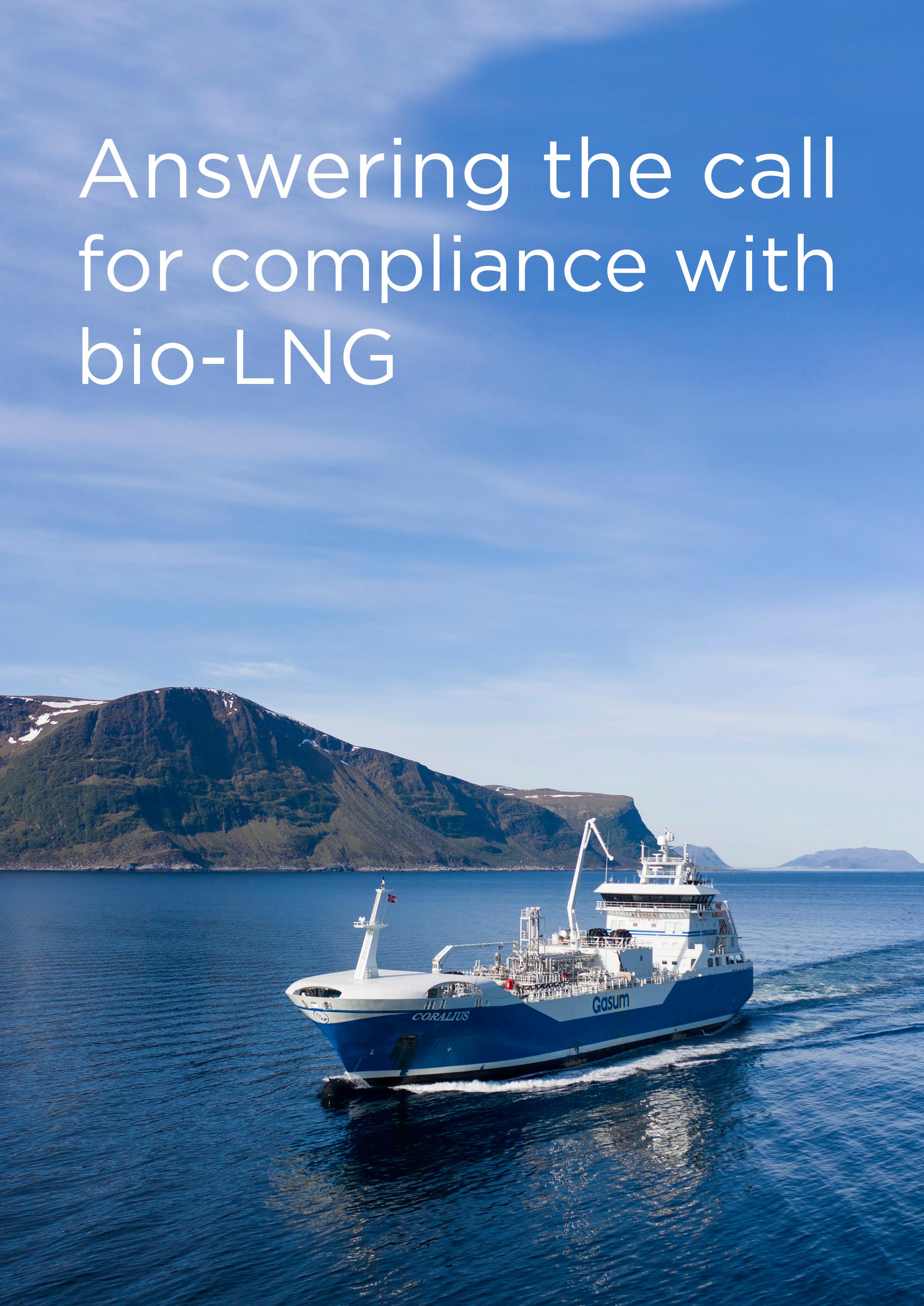
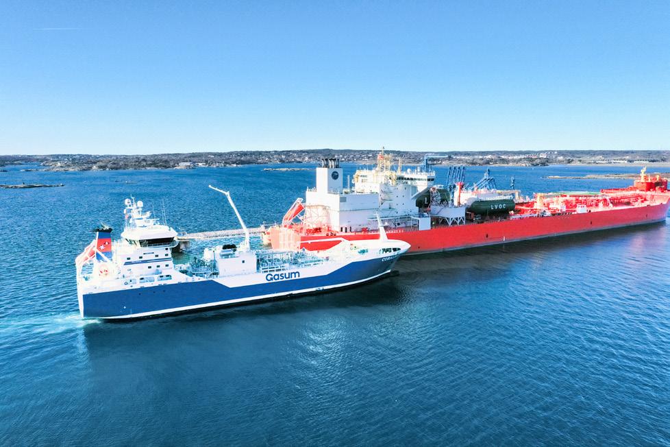
Figure 1. Coralius bunker vessel.
the batteries of a ship would be too big and heavy for it to carry any other cargo or people.
However, this does not affect the need to lower emissions; 90% of global cargo is transported by sea, rendering shipping a vital industry for people and companies. Maritime shipping contributes up to 3% of the world’s total carbon dioxide (CO 2 ) emissions and 10 – 15% of global sulfur oxides (SOX ) and nitrogen oxides (NOX ). Thus, the industry must find alternative ways to steer itself into a greener future.
What exactly is FEUM?
Currently, the industry is facing tightening regulations, such as the FuelEU Maritime Directive (FEUM). FEUM requires ships of 5000 gross t and above trading within and in and out of the EU to progressively reduce greenhouse gas emissions.
The directive calculates ships’ well-to-wake emissions instead of the traditional tank-to-wake approach. This captures emissions from fuel extraction, production, and transportation (well-to-tank), as well as combustion emissions (tank-to-wake). The greenhouse gas intensity targets are compared against a calculated baseline from 2020. From 2025 – 2029, the reduction must be -2% and it will increase gradually, reaching -31% in 2040.
The measures are forcing operators to consider alternative, low emission ways to power their vessels or to come up with other ways to comply with the regulations. However, the alternatives are limited. The operators can either use low-emission biofuel in their vessels, get compliance through FEUM pooling, or opt for paying the penalties from undercompliance.
Bio-LNG is readily available and future-proof
Bio-LNG is one of the few readily-available maritime fuels that can help comply with the FEUM regulations. It is a renewable fuel that is produced from various types of organic waste, such as household bio waste, biodegradable waste from enterprises and industrial facilities, manure and field biomass from agriculture, and sludge from wastewater plants.
Bio-LNG is interchangeable with LNG, meaning it can be used by LNG-powered vessels. Like LNG, using bio-LNG removes SOX and all particle emissions, and reduces NOX emissions of up to 85%. Using bio-LNG can also help to
reduce greenhouse gas emissions during the entire lifecycle by 90% on average when compared to fossil fuel use.
In the future, bio-LNG will also be interchangeable with synthetic e-LNG, making it a future-proof choice. The Nordic countries alone could produce over 400 TWh of bio-LNG and e-LNG, an amount nearly equivalent to the total energy currently used for refuelling ships across the EU. LNG, bio-LNG, and e-LNG are chemically identical meaning these fuels can also use the same, readily-available infrastructure – adding to their future-proof nature.
Bio-LNG creates compliance and over-compliance
Bio-LNG also enables the second option that builds maritime industry’s low-emission future: pooling. Pooling is a novel and practical solution for FEUM compliance for companies unable to utilise bio-LNG or other biofuels directly.
Pooling services combine vessels that are over-compliant with those that need compliance via a reliable and transparent service provider, the pooling manager. The service enables shipowners to meet emissions targets without having to immediately upgrade vessels or switch fuels while still promoting the use of low-emission, renewable maritime fuels, such as bio-LNG. In addition, the pooling manager will handle the administrative burden of compliance which enables the owners to focus on their core operations.
As a service, pooling is not limited by geography and is available to all shipping companies calling at EU ports, regardless of flag, route, or home market. Whether operating in the Mediterranean, the North Sea, or the Baltic Sea, shipowners can benefit from pooling arrangements to meet FEUM requirements efficiently.
Regulation increases the demand for bio-LNG
Pooling services do not offer limitless compliance. The over-compliance must always be realised by an actual vessel. For example, compliance for Gasum’s pooling customers is generated by several different vessels, such as Viking Line’s two Ro-Pax vessels, Viking Glory and Viking Grace, that operate daily the route between Turku in Finland and Stockholm in Sweden, carrying both passengers and cargo across the Baltic Sea. In addition to generating compliance for Gasum’s pool, both also run on bio-LNG produced and supplied by Gasum.
This is a good example of how FEUM also increases the demand for bio-LNG indirectly. By joining a pool, shipping companies contribute to biofuel production even if they are unable to burn the fuel themselves. The pooling services create a self-reinforcing system where economic and environmental incentives align. A recent study by the Mærsk McKinney Møller Center for Zero Carbon Shipping found that the pooling mechanism incentivises investment in advanced technologies and alternative fuels, potentially closing the cost gap between fossil fuels and greener alternatives.
Pooling services offer clear benefits to all parties involved: shipowners achieve compliance cost-effectively
Figure 2. Coralius bunker vessel.
without operational disruption, while compliance generators (that are shipowners operating on low-emission fuels) gain access to biofuels at more competitive prices.
Controlling the whole value chain adds to reliability
When choosing a partner for compliance, whether the chosen mean is biofuel or pooling, reliability, transparency, and certification are key. As the compliancy must be verified, it is crucial that the service provider can offer certificates that prove the services’ reliability and accuracy. In addition, it is an advantage if the provider offers full control over the value chain, from fuel production to emissions accounting.
For example, Gasum uses ISCC-certified processes and manages its own bio-LNG production and distribution network which includes bunkering services at sea and in ports across Europe. Gasum’s fleet comprises of three bunkering vessels with an additional vessel joining the fleet in 2027. In addition to ship-to-ship bunkering, Gasum offers truck-to-ship bunkering and ex-pipe and installation deliveries.
All of Gasum’s bunkering vessels also generate compliance for Gasum’s FEUM pooling customers. The vessels run on bio-LNG produced or sourced by Gasum, making it easy to stay on track of the compliance, as well as the origin of the fuel.
The growing demand for bio-LNG across sectors and limited feedstock availability means supply reliability is a concern. When the provider manages the whole value chain from fuel production to supply and even to pooling, it can expand the fuel ecosystem as the demand increases, increasing its production capacity and strengthening the infrastructure.
Opting for penalties will cost in reputation and resources
As the regulation progresses, shipowners and shipping companies need to take conscious actions towards compliance. For some companies, paying penalties will be their chosen method to comply, but it is widely regarded as the worst one. In addition to bringing no environmental benefits whatsoever, its cost effects are significant.
The penalty for undercompensating is set at €2400/t of conventional very low sulfur fuel oil (VLSFO) energy equivalent. This translates to roughly €632/t of CO 2 -e for VLSFO.
To put the penalties into perspective: without any compliance measures a medium-sized bulk carrier consuming around 10 000 tpy of conventional fuel could face penalties of up to €24 million annually. Even smaller vessels operating in regional trade could be exposed to millions of euros in fines. And as more companies adapt to the regulation, opting to pay penalties can also become a reputational issue.
The first year of FEUM will show
the way
Bio-LNG’s value and demand as a cost-effective, traceable, and reliable fuel for shipping companies and vessels
generating compliance for pooling services will increase. In addition, the demand for reliable and transparent partners supplying the fuel and services related to it, like bunkering and pooling, will increase. By the end of April 2026, maritime companies’ emission and compliance reports are assessed and their compliances calculated for the pooling reporting year of 2025.
As such, the year 2025 gives a picture of compliance and its effects on shipowners and compliance providers. At the time of writing, it is still unclear how the costs between shipowners and operators will be divided, and how much the regulation will actually increase the demand.
Even though there are still some questions that remain unanswered, the directive is already in force, and the second year well in motion. This means there is an urgency to act. According to DNV’s estimates, the maritime industry could face up to seven times more deficit than surplus of compliance units. Early movers who secure efficient compliance solutions, like pooling, are therefore likely to gain a significant financial advantage.
There is no future where ships will not sail the seas. However, there will be a future where the ships sailing will be cleaner and greener than today. Thus, the main question is: who will get there first?
Figure 3. Coralius carrying out a ship-to-ship bunkering operation. Source: Sirius Shipping.
Figure 4. A ship-to-ship bunkering operation being carried out at sea. Source: Sirius Shipping.
Julien Boulland, Sustainability
Strategy Leader,
Bureau
Veritas Marine
& Offshore, outlines LNG’s role in delivering measurement emissions reductions in the shipping industry.
There is no debate about the need to decarbonise shipping. Pressure on the industry to evidence tangible greenhouse gas reductions is intensifying as the International Maritime Organization’s (IMO) 2030 checkpoint draws near. Ambition for a net-zero framework (NZF), on hold until another attempt to adopt, would represent a landmark regulatory evolution that seeks to unify the current fragmented policy landscape. The IMO’s proposed Global Fuel Standard, based on well-to-wake (WtW) greenhouse gas fuel intensity (GFI), is to hold ships accountable not only for onboard emissions, but also for those generated upstream in fuel production, transport, and storage. Compliance requirements would be planned to take effect after 2028. It is important to note that shipping has already made significant progress, with continuous new innovations in vessel design (for instance, in the chemistry of the paint used to protect vessels) and voyage efficiency. In parallel,
policy implementation needs to accurately reflect real-world performance and technological progress if it is to continue to support viable energy transition pathways. It is important that LNG is recognised as an important fuel pathway in the energy transition.
LNG adoption
LNG has been safely transported by sea for nearly 60 years. Over that time, the industry has built a formidable safety record supported by rigorous standards, operational protocols, and engineering expertise.
More recently, LNG has matured as a marine fuel. Compared with conventional fuel oil, LNG reduces carbon dioxide emissions while virtually eliminating sulfur oxides and particulate matter and significantly lowering nitrogen oxides. From an air quality standpoint, these improvements have had measurable positive impacts, particularly in port
communities and emission control areas. However, from a greenhouse gas standpoint, methane emissions along the value chain (from extraction to combustion on board) need to be controlled and mitigated to avoid negating the positive aspects of carbon dioxide emissions reductions.
Importantly, LNG’s adoption has not occurred in a policy vacuum. Public authorities, particularly within Europe, actively encouraged the uptake of LNG as part of the air quality improvement narrative. This regulatory clarity and financial incentive, backed with strong engineering know-how, provided confidence to shipowners and investors to engage with LNG as a lower emissions fuel. The response was decisive. By mid-2025, there were approximately 800 LNG-fuelled ships in operation, excluding the 700-strong carrier fleet, with more than 1000 additional ships on order. Crucially, an estimated 37% of the new order book by gross tonnage is LNG fuelled – meaning the largest,1 highest-emitting vessel classes, such as large tankers and containerships, will require a significant and sustained supply of LNG to support their operations.
The net-zero pathway
LNG is not merely a transitional solution in isolation. It is the foundation from which the development of renewable gaseous fuels such as bio-LNG and synthetic LNG (e-LNG) will emerge. The engines, tanks, and bunkering infrastructure developed for LNG today are directly compatible with the future integration of renewable methane. This compatibility offers a powerful advantage in an industry where asset lifecycles stretch across decades. Investment in LNG infrastructure is therefore an investment in a scalable pathway towards lower and ultimately near-zero carbon fuels.
Recent industry developments further underline LNG’s continuing evolution. During LNG2026, Bureau Veritas Marine & Offshore (BV) reinforced its commitment to supporting innovation across the LNG value chain. A joint development project with Hanwha Ocean was announced, which will advance the design of a 174 000 m3 membrane-type LNG carrier, optimising structural performance and operational efficiency to meet the demands of a growing LNG trade. Meanwhile, HD Hyundai Heavy Industries received approval in principle (AiP) from BV for a 20 000 m3 LNG bunkering vessel design, demonstrating continued progress in expanding bunkering capacity and flexibility.
Complementing these technical milestones, BV has established a dedicated Gas Center of Excellence in Doha, Qatar, to consolidate global expertise in LNG and gas development, whilst sharing BV’s extensive expertise in vessel classification, compliance, and lifecycle optimisation. Together, these initiatives signal a sector that is actively investing, innovating, and preparing for long-term growth.
Following the data
However, under the NZF as presented for adoption in 2025, the WtW methodology introduced a complexity that would have to be carefully managed. Under the framework as approved in April 2025 but not adopted, LNG faces partial Tier 1 penalties from 2028 and potential Tier 2 non-compliance from 2030 due to methane emissions calculations embedded in default well-to-tank factors. The NZF sets a base (Tier 2) GFI target requiring a 4% reduction by 2028, rising to 30% by 2035, with remedial units priced
at US$380/t CO2-e for non-compliance. These defaults are largely derived from conservative lifecycle assessment models that may not reflect current supply chain performance or technological advances in methane management.
Significant progress has been made in reducing methane slip from modern marine engines, particularly advanced two-stroke dual-fuel designs. Improvements in combustion efficiency and engine architecture have materially lowered unburnt methane emissions.
Additionally, the difference between methane slip and fugitive emissions needs to be better understood. Shipping is managing methane slip, but fugitive emissions across natural gas value chains need to be measured and managed. There are good gas value chains and bad ones. Additionally, encouraging a biogas value chain will help capture and use emissions from human activity (from agriculture, for example). These are all areas where the principle of following – and understanding – the data becomes critical.
A static methodology in a rapidly evolving technological environment creates unintended consequences. It may discourage investment in LNG and renewable LNG at precisely the moment when infrastructure and supply chains are scaling. To avoid this, the NZF should incorporate a formal mechanism for regularly updating well-to-tank emission factors based on verified data – a position BV has actively championed through its technical submissions to the IMO. Such an approach would reward real-world improvements, maintain regulatory credibility, and provide the LNG sector with the confidence required for continued long-term investment.
BV is actively contributing to this process through the International Association of Classification Societies, which holds observer and consultative status at the IMO. As a leading classification society with deep expertise across the LNG value chain, from carrier design and bunkering infrastructure to cargo systems and fuel certification, BV is well placed to provide the objective technical evidence that regulators need.
By submitting verified data on LNG, bio-LNG, and e-LNG emission factors and supporting national delegations with rigorous technical expertise, BV’s aim is to ensure that regulatory decisions are grounded in engineering realities rather than theoretical assumptions.
Beyond emissions accounting, the practical deployment of renewable LNG also depends on regulatory recognition of mechanisms such as mass balancing and virtual liquefaction. Within the EU, vessels carrying blended cargoes of LNG and bio-LNG can account for renewable content at the voyage level, enabling flexible scaling of low-carbon fuels. Some terminals are able to virtually liquefy biomethane injected into the gas grid by matching equivalent LNG volumes, avoiding unnecessary processing costs. These commercially viable mechanisms facilitate renewable uptake within existing infrastructure. If international rules disregard such practices, they risk slowing progress rather than accelerating it.
The broader energy context must also be acknowledged. Natural gas continues to play a central role in the global energy mix, frequently displacing coal and delivering net reductions in emissions. At the same time, green methanol and green ammonia – while promising – face supply constraints, cost challenges, and infrastructure gaps.
Widespread availability at competitive scale remains some distance away. In contrast, LNG is widely available, supported by mature infrastructure and compatible with renewable derivatives. It represents the most immediately scalable lower-carbon marine fuel currently accessible to the global fleet.
That fleet reality cannot be ignored. The majority of vessels operating today burn fuel oil, and many will remain in service well into the 2040s. For most, radical retrofitting to alternative fuels is neither technically straightforward nor economically viable. Immediate emissions reductions must therefore come from practical solutions that can be deployed now. LNG, biofuels, and efficiency measures offer such opportunities.
Indeed, fuel transition is only one element of the decarbonisation equation. Smarter ship design, enhanced hull coatings, wind-assisted propulsion, carbon capture technologies, and operational optimisation tools all have critical roles to play. Initiatives such as the Blue Visby Solution demonstrate how improved voyage co-ordination can reduce unnecessary waiting times and associated emissions. A holistic approach, combining fuel innovation, efficiency gains, and digital optimisation, is essential.
With the extraordinary MEPC session in October 2025 having adjourned without formal adoption of the NZF, reconvened talks are now expected in 2026, with implementation guidelines to be finalised at MEPC 84; the industry has both a window and a responsibility to ensure that ambition is aligned with pragmatism. LNG is not a silver bullet, nor is it the final destination. It is, however, a proven,
scalable, and investable platform that enables immediate emissions reductions while creating a bridge to renewable and synthetic methane fuels. Penalising LNG on the basis of outdated or overly conservative emission factors would undermine confidence, deter investment, and slow the very transition regulators seek to advance. BV urges regulators to use the additional time available before final adoption to ensure that the well-to-tank default values embedded in the GFI methodology reflect verified, current data.
Following the path
The path to net zero will not be linear. It requires flexibility, technical realism, and sustained collaboration between regulators, shipowners, fuel producers, and classification societies. Above all, it requires regulatory frameworks that evolve in step with technology and data. By adopting a dynamic, evidence-based approach to well-to-tank emissions accounting, the NZF can reinforce the LNG-to-bio-LNG transition.
Shipping’s decarbonisation journey demands both urgency and clarity. As a classification society, BV’s role is to ensure that standards and regulations are technically sound, practically implementable, and founded on evidence. If the NZF follows the data, recognises real-world progress, and preserves viable transition pathways, LNG will continue to play a vital role in delivering measurable reductions.
References
1. ‘Global fleet’, SEA-LNG, https://sea-lng.org/why-lng/ global-fleet/
Cyber governance: What pipeline boards must know
A conversation about board-level cyber responsibility in oil and gas. Featuring Brittany Bacon, Partner in Global Privacy and Cybersecurity at Hunton Andrews Kurth LLP.
From the regulatory aftermath of the Colonial Pipeline attack to SEC disclosure rules, fiduciary duties, vendor risk, cyber insurance disputes, and evidence preservation during incident response: this conversation dives into what ‘reasonable’ really means in the eyes of regulators and courts.
As digitalisation accelerates and operational technology remains vulnerable, cybersecurity is a board-level responsibility. Brittany outlines the practical questions that directors should be asking.
LISTEN NOW
CATCH UP ON RECENT EPISODES
Greene Tweed
Rockwell Automation
Black & Veatch
Listen and subscribe here
Brittany Bacon, Hunton Andrews Kurth LLP Elizabeth Corner
Remco Krul, Nordsol, highlights the bio-LNG project in Wilp, the Netherlands, as a way to demonstrate how decentralised liquefaction for small scale bio-LNG is a feasible option for the decarbonisation of heavy-duty transport and shipping.
Decarbonising heavy-duty transport and shipping remains one of the more demanding aspects of the European energy transition. These sectors rely on high energy-density fuels, long range, and fast refuelling, which makes full electrification challenging in many applications. LNG is already established in heavy road transport and in maritime segments, where there is significant potential for further growth as the sector pursues its sustainability goals. Bio-LNG (liquefied biomethane produced from organic feedstocks) offers a route to reduce greenhouse gas (GHG) emissions while using existing LNG engines, storage, and distribution infrastructure.
An important question for the transport sector is whether bio-LNG production can be scaled to meet growing demand. To achieve this, as much local waste as possible needs to be converted into biogas and then into bio-LNG. Many existing biogas plants are relatively small, located close to waste sources, and not always connected to the gas grid.
Decentralised liquefaction directly at these sites makes it possible to move energy to offtakers via the liquefied gas value chain and helps prevent existing biogas assets from becoming stranded.
The Wilp bio-LNG plant is an example of this approach. It is a commercial bio-LNG facility located at Attero’s existing waste processing and biogas site in Wilp, the Netherlands.
The project involves three key organisations: Nordsol, as technology developer and owner–operator of the liquefaction unit; Attero, as waste processor, biogas producer, and owner–operator of the biogas upgrading and carbon dioxide (CO2) liquefaction units; and the European Climate, Infrastructure, and Environment Executive Agency (CINEA), who manages the Innovation Fund, a programme financed by the EU Emission Trading System revenues supporting the project. Attero and Nordsol have implemented a small scale liquefaction concept tailored to distributed biogas sites, creating a reference plant for decentralised bio-LNG production.
From concept to operation
Technology objectives
The process used at Wilp is based on Nordsol’s iLNG process design. It was developed specifically for small scale, decentralised applications, rather than as a scaled-down version of large LNG plants. The main objectives of the iLNG process are:
z To reduce specific energy consumption through process integration.
z Achieve high methane recovery with zero methane vent.
z Maintain a compact, modular footprint suitable for industrial and agricultural biogas sites.
z Minimise equipment count and apply a continuous process, without heat requirement.
z Ensure that automation, operability, and maintenance meet the requirements of biogas producers, as well as bio-LNG offtakers.
Core process architecture
The iLNG process converts raw biogas into two main products: bio-LNG and high-purity biogenic liquid CO2
Biogas from anaerobic digestion typically contains methane, CO2, water vapour, hydrogen sulfide (H2S), and traces of volatile organic compounds (VOCs). The process begins with dehumidification and removal of H2S and VOCs to protect downstream equipment, meet LNG quality specifications, and ensure stable operation.
After pretreatment, the bulk of the CO2 is removed by a standard biogas-to-biomethane upgrading unit. Subsequently, the remaining CO2 and traces of water are separated from the biomethane using membranes only. Patented Flash-2-SweepTM technology improves the performance of the last membrane stage by a factor of 20, creating liquefaction-ready biomethane. Flash-2-Sweep boosts membrane performance by sweeping the low-pressure permeate side with flash gas and boil-off gas (BOG) from the liquefaction unit. The permeate is routed back to the biogas compressor, preventing any loss of biomethane.
The biomethane is liquefied in a cryogenic section that uses a reverse Brayton cycle based on methane gas expansion through a single turboexpander. It is a simplified version of the efficient AP-C1 process developed by Air Products.1 The process uses treated biomethane as the refrigerant, rather than nitrogen, which makes it particularly efficient in the required temperature range.
CO2 in the biogas is captured and liquefied as a high-purity product rather than vented, improving the emissions profile and enabling reuse in industrial or horticultural applications where markets exist. Biogenic CO2 will also serve as the feedstock for synthetic fuels, such as sustainable aviation fuel or e-methane.
By integrating upgrades and liquefaction in this way, the iLNG process concentrates functionality into a compact package with low equipment count, suited to distributed biogas facilities.
Partnership framework
Bio-LNG Wilp is the outcome of a co-operation that brings together technology, feedstock, and public support.
Nordsol developed the iLNG concept and owns and operates the biomethane liquefaction unit at Wilp. Its responsibilities include process design from biogas to bio-LNG, equipment specification, and operational control of the Flash-2-Sweep and liquefaction process, as well as truck loading.
Attero operates the Wilp waste processing site, which includes anaerobic digestion of organic waste to produce biogas. Attero owns and operates the biogas upgrading and CO2 liquefaction units at the site.
CINEA supports the project through the Innovation Fund, the programme that aims to accelerate the deployment of low-carbon technologies. CINEA contributes with financial support and monitors progress and results for potential replication.
Figure 1. Integrated bio-LNG production process.
Figure 2. Flash-2-Sweep boosts membrane performance by sweeping the permeate side with flash gas.