November N b 22021 021
Rapid and Accurate Analysis of Sulphur and Chlorine in Biofuels by XRF (SS IPVM\LSZ·ISLUKLK VY UV[·T\Z[ TLL[ JLY[HPU Z\SWO\Y YLN\SH[VY` SPTP[Z 0U HKKP[PVU ZVTL IPVM\LSZ JVU[HPU MHPYS` OPNO SL]LSZ VM JOSVYPUL ^OPJO JHU JH\ZL JVYYVZPVU KHTHNL K\YPUN HUK HM[LY [OL WYVK\J[PVU Z[HNLZ X-ray Fluorescence (XRF) delivers rapid and accurate results for testing sulphur and chlorine in biofuels IHJRLK I` PU[LYUH[PVUHS Z[HUKHYK [LZ[ TL[OVKZ (:;4 0:6 L[J (K]HU[HNLZ VM ?9- [LJOUVSVN` PUJS\KL P[Z UVU KLZ[Y\J[P]L UH[\YL LHZ` ZHTWSL WYLWHYH[PVU WYVJLZZ HUK X\PJR YLZ\S[Z PU HKKP[PVU [V HJJ\YHJ` [OH[ PZ VU WHY ^P[O HS[LYUH[P]L [LJOUVSVNPLZ SPRL <=- \S[YH]PVSL[ Å \VYLZJLUJL >L JVUK\J[LK H Z[\K` \ZPUN :PUKPL *S ?9- ILUJO[VW HUHS`ZLY [V [LZ[ Z\SWO\Y HUK JOSVYPUL PU LPNO[ YLHS ^VYSK ZHTWSLZ! ) ) .HZVPS /`KYV[YLH[LK =LNL[HISL 6PS 9HWLZLLK 4L[O`S ,Z[LY :V`ILHU 4L[O`S ,Z[LY ;HSSV^ 4L[O`S ,Z[LY HUK <ZLK *VVRPUN 6PS 4L[O`S ,Z[LY /H]PUN [OL JVYYLJ[ Z\SWO\Y ]HS\L MVY IPVM\LSZ PZ JYP[PJHS HZ [OL` HYL [`WPJHSS` ISLUKLK ^P[O M\LSZ [OH[ OH]L H TH_PT\T ZWLJPÄ JH[PVU VM TN RN MVY Z\SWO\Y TN RN PU [OL <: ;OPZ PZ PTWVY[HU[ [V UV[L ILJH\ZL V_`NLU HIZVYIZ ?9- ZPNUHSZ HUK HZ H YLZ\S[ JHU JH\ZL HUHS`ZLYZ [V YLWVY[ MHSZLS` SV^ Z\SWO\Y HUK JOSVYPUL JVUJLU[YH[PVUZ
Table 1: Tallow Methyl Ester (TME) (mg/kg) Test average of 10 repeats st. dev. RSD%
Sulphur (300s)
Sulphur Corrected
Chlorine (300s)
Chlorine Corrected
8.18
9.74
0.48
0.57
0.45 5.48
0.53 5.48
0.07 15.06
0.09 15.06
Table 2: Used Cooking Oil Methyl Ester (UCOME) (mg/kg) Test average of 10 repeats st. dev. RSD%
Sulphur (300s)
Sulphur Corrected
Chlorine (300s)
Chlorine Corrected
7.74
9.22
425
509
0.40
0.48
2.88
3.45
5.16
5.16
0.68
0.68
(U L_HTWSL VM [OL L_JLSSLU[ YLWLH[HIPSP[` VI[HPULK PU [OPZ Z[\K` I` :PUKPL *S PZ KLTVUZ[YH[LK PU ;HISLZ HUK ! ;4, HUK <*64, ZHTWSLZ ;OL Z\TTHYPaLK KH[H VM [OL [^V ZHTWSLZ ZOV^ [OL H]LYHNL VM YLWLH[Z ^P[O [OLPY YLZWLJ[P]L Z[HUKHYK KL]PH[PVU HUK YLSH[P]L Z[HUKHYK KL]PH[PVU WLYJLU[ HZ ^LSS HZ [OL JVYYLJ[LK YLZ\S[Z MVY V_`NLU JVU[LU[ (SS KH[H OHZ ILLU HJX\PYLK \UKLY YLWLH[HIPSP[` JVUKP[PVUZ HUK ZOV^ ]LY` HJJ\YH[L YLZ\S[Z
=PL^ [OL M\SS Z[\K` I` ]PZP[PUN xos.com/biofuelsXRF-HCE
XOS is a leading manufacturer of application-specific X-ray analyzers, VɈ LYPUN LSLTLU[HS HUHS`ZPZ ZVS\[PVUZ [OH[ PTWYV]L W\ISPJ ZHML[` HUK J\Z[VTLY Lɉ JPLUJ` PU PUK\Z[YPLZ SPRL WL[YVSL\T JVUZ\TLY WYVK\J[Z HUK LU]PYVUTLU[HS JVTWSPHUJL -VY WL[YVSL\T HWWSPJH[PVUZ ?6: VɈ LYZ WVY[HISL SHI HUK WYVJLZZ HUHS`aLYZ ^P[O \UYP]HSLK WYLJPZPVU H[ [OL W\ZO VM H I\[[VU ?6:» :PUKPL® HUK *SVYH® ?9- HUHS`ZLYZ KLSP]LY YHWPK HUK HJJ\YH[L YLZ\S[Z ^P[O L_JLW[PVUHS YLWYVK\JPIPSP[` MVY IV[O Z\SWO\Y HUK JOSVYPUL PU IPVM\LSZ ^P[OV\[ [OL ULLK MVY H TH[YP_ TH[JOLK JHSPIYH[PVU I` ZPTWS` HWWS`PUN H JVYYLJ[PVU MHJ[VY [V [OL YLZ\S[Z ;OPZ HSSV^Z WYVMLZZPVUHSZ [V JLY[PM` [OLPY IPVM\LS WYVK\J[Z TVYL Lɉ JPLU[S` [OHU ^P[O V[OLY TL[OVKZ
:PUKPL *S KLSP]LYZ L_JLW[PVUHS YLWYVK\JPIPSP[` MVY IV[O Z\SWO\Y HUK JOSVYPUL HUHS`ZPZ HUK JHU TLHZ\YL IV[O LSLTLU[Z JVUJ\YYLU[S` :HTWSLZ HYL TLHZ\YLK KPYLJ[S` ^OPJO TLHUZ P[ JHU HUHS`aL L]LU [OL OLH]PLZ[ VM O`KYVJHYIVUZ SPRL JY\KL VPS VY JVRLY YLZPK\HSZ ^P[OV\[ [OL OHZZSL VM IVH[Z PUQLJ[VYZ M\YUHJLZ VY JOHUNPUN KL[LJ[VYZ Sindie +Cl complies with ASTM D2622, and therefore meets the regulatory limit of ASTM D6751 and ASTM D7467. It also meets the precision requirements for ISO 20884 and can be used for EN 14214.
+1 518.880.1500 | info@xos.com | xos.com
CONTENTS November 2021 Volume 26 Number 11 ISSN 1468-9340
05 Comment
29 An iron will
07 World news 10 Sub-Saharan Africa: can downstream move up? Contributing Editor, Nancy D. Yamaguchi, explains why there is emerging hope for the downstream sector in Sub-Saharan Africa, despite the challenges presented by the COVID-19 pandemic.
18 A running start to net zero Ken Chlapik, Dominic Winch, and Carl Keeley, Johnson Matthey, outline why it is important to use all of the tools and technologies available today to reduce CO2 emissions in order to achieve a running start to net zero targets.
Qianqian Liu, Zhenyu Chen, Haitao Song, Chunfang Chen, Rui Bai, Ning Li and Liqiang Liu, SINOPEC, China, explore the application of a high iron tolerant catalyst in residue FCC.
32 Moving toward a decarbonised world Dr Klaus Brun, Elliott Group, explores the role of compressors in a decarbonised energy economy.
39 Assessing recovery systems A. Betti, Compression Service Technology S.r.l, Italy, alongside M. Ruggiero, M. Astuti, D. Barbati, and S. Raciti, Snam S.p.a, Italy, evaluate the pros and cons of different recovery systems for reducing leakages from natural gas compression and storage stations.
43 Up to the challenge David Walsh, Howden, Scotland, introduces a method for controlling the main air blowers within the sulfur recovery process, which will help to improve energy efficiency.
47 Smart surveys Kaveh Ebrahimi, Fluor Ltd, and Cristiana Nascimento, Fluor B.V., provide an engineering perspective on the best practices for successful modern surveys of existing equipment.
53 The missing link Manas Dutta, Honeywell Process Solutions (HPS), India, examines objective operator improvements with machine learning and advanced analytics.
57 Operating excellence without capital expense
25 The key role of catalysts Dr Meritxell Vila, MERYT Catalysts & Innovation, Spain, explains the importance of catalysts in processing CO2 to chemicals and fuels, and takes a look at the latest research from experts in the field.
Matt Thundyil, Dave Seeger and Carl Hahn, Transcend Solutions LLC, USA, explore the basic principles underlying easy opportunities for achieving operating excellence in plants.
63 Pumps & Valves Q&A Hydrocarbon Engineering talks to a number of leading experts in pumps & valves about technology innovations, environmental regulations, equipment reliability and safety, as well as the future of the sector following the COVID-19 pandemic.
THIS MONTH'S FRONT COVER JOIN THE CONVERSATION follow
@HydrocarbonEng
like
Hydrocarbon Engineering
join
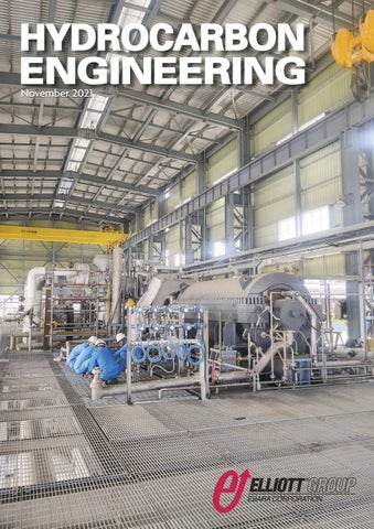
Installation of an Elliott Propylene Refrigerant Compressor in a 1000 KTA ethylene plant under construction in China.
2021 Member of ABC Audit Bureau of Circulations
Copyright© Palladian Publications Ltd 2021. All rights reserved. No part of this publication may be reproduced, stored in a retrieval system, or transmitted in any form or by any means, electronic, mechanical, photocopying, recording or otherwise, without the prior permission of the copyright owner. All views expressed in this journal are those of the respective contributors and are not necessarily the opinions of the publisher, neither do the publishers endorse any of the claims made in the articles or the advertisements. Printed in the UK.
Hydrocarbon Engineering
CBP006075
COMMENT CONTACT INFO MANAGING EDITOR James Little
james.little@palladianpublications.com SENIOR EDITOR Callum O'Reilly
callum.oreilly@palladianpublications.com SALES DIRECTOR Rod Hardy
rod.hardy@palladianpublications.com SALES MANAGER Chris Atkin
chris.atkin@palladianpublications.com SALES EXECUTIVE Sophie Barrett
sophie.barrett@palladianpublications.com PRODUCTION Kyla Waller
kyla.waller@palladianpublications.com DIGITAL EDITORIAL ASSISTANT Bella Weetch
bella.weetch@palladianpublications.com DIGITAL EVENTS COORDINATOR Louise Cameron
louise.cameron@palladianpublications.com VIDEO CONTENT ASSISTANT Molly Bryant
molly.bryant@palladianpublications.com DIGITAL ADMINISTRATOR Lauren Fox
lauren.fox@palladianpublications.com ADMIN MANAGER Laura White
laura.white@palladianpublications.com CONTRIBUTING EDITOR Nancy Yamaguchi Gordon Cope
SUBSCRIPTION RATES Annual subscription £110 UK including postage /£125 overseas (postage airmail). Two year discounted rate £176 UK including postage/£200 overseas (postage airmail). SUBSCRIPTION CLAIMS Claims for non receipt of issues must be made within 3 months of publication of the issue or they will not be honoured without charge.
APPLICABLE ONLY TO USA & CANADA Hydrocarbon Engineering (ISSN No: 1468-9340, USPS No: 020-998) is published monthly by Palladian Publications Ltd GBR and distributed in the USA by Asendia USA, 17B S Middlesex Ave, Monroe NJ 08831. Periodicals postage paid New Brunswick, NJ and additional mailing offices. POSTMASTER: send address changes to HYDROCARBON ENGINEERING, 701C Ashland Ave, Folcroft PA 19032.
15 South Street, Farnham, Surrey GU9 7QU, UK Tel: +44 (0) 1252 718 999 Fax: +44 (0) 1252 718 992
CALLUM O'REILLY SENIOR EDITOR
“
Somebody is pranking us. I bet you a thousand dollars it’s not real. I’m going back to bed.” These were the words of Prof. David MacMillan, replying to a text message from Prof. Benjamin List who had contacted him to say that he had just received a phone call from the Royal Swedish Academy of Sciences to tell him that they had both won the 2021 Nobel Prize in Chemistry. Although he may have lost the bet, MacMillan confirmed that he was “very happy” to discover that the phone call was, in fact, genuine. The two scientists were awarded the prize for the discovery of a new class of catalyst that has revolutionised advances in pharmaceutical research and allowed scientists to construct catalysts with considerably less impact on the environment. Back in 2000, Prof. MacMillan and Prof. List – working independently of each other – developed asymmetric organocatalysis, which builds upon small organic molecules. The Nobel Committee said that developments in this area since 2000 can be likened to a “gold rush” in the field. Within a decade of their first papers on the topic, more than 1000 papers a year were being published in the general area of organocatalysts. Organic catalysts have a stable framework of carbon atoms, to which more active chemical groups can attach. These often contain common elements such as oxygen, nitrogen, sulfur or phosphorus. This means that these catalysts are both environmentally friendly and cheap to produce. The rapid expansion in the use of organic catalysts is primarily due to their ability to drive asymmetric catalysis. When molecules are being built, situations often occur where two different molecules can form that are each other’s mirror image. Chemists will often only want one of these, particularly when producing pharmaceuticals. Organic catalysts can be used to drive multitudes of chemical reactions, which researchers can use to more efficiently construct anything from new pharmaceuticals to molecules that can capture light in solar cells. In awarding the prize, the Nobel Committee pondered why no one had come up with this simple concept sooner. The Committee suggests that Prof. List and Prof. MacMillan were able to see past strong preconceptions about how the world should work – such as the idea that only metals or enzymes can drive chemical reactions – to find an ingenious solution to a problem that chemists have struggled with for decades. Innovations in catalyst technology are also playing a crucial role in the energy transition. This issue of Hydrocarbon Engineering includes a detailed article from Dr Meritxell Vila, General Manager of MERYT Catalysts & Innovation, looking specifically at the importance of catalysts in processing CO2 to chemicals and fuels. The article (starting on p. 25) outlines a number of projects in this field that are taking place in research centres across the world. We hope you enjoy this piece, and the many other excellent technical articles packed into this issue of Hydrocarbon Engineering. HYDROCARBON
ENGINEERING
5
November 2021
Challenging future ahead? We are here to support you! Disruption is on the horizon. The conventional refinery industry shifts its focus to biofuels and invests in new technologies. BASF Refining Catalysts is working closely with refineries on introducing bio-feedstock into their operations. Get in touch with our global FCC experts virtually – or meet us in person at the ERTC 2021 in Madrid. catalysts.basf.com/refinery-catalysts
WORLD NEWS USA | Linde
starts up new hydrogen facility
L
inde recently announced that it has started up a new hydrogen production facility in Texas, US, bringing the company’s total US Gulf Coast hydrogen capacity to approximately 1.5 billion ft3/d. Linde’s new plant has started supplying high-purity hydrogen to the Phillips 66 Sweeny Refinery in Old Ocean, Texas, under a long-term supply agreement. The new facility is located on Linde’s approximately 600 km US Gulf Coast hydrogen pipeline, which runs from Lake Charles, Louisiana,
to Freeport, Texas, and has now been extended to connect with the Sweeny Refinery. In addition to supplying Phillips 66, the facility will meet the growing demand for hydrogen from other customers in the region. Jeff Barnhard, Vice President South Region, Linde, said: “Supported by multiple supply sources and an innovative high-purity hydrogen storage cavern, this infrastructure enables us to provide our customers with reliable long-term supply.”
The Netherlands | Neste
and Ravango to set up chemical recycling JV
N
este and Ravago have announced plans to establish a joint venture to build an industrial facility for chemical recycling in North Sea Port in Vlissingen, the Netherlands. The facility is intended to be the starting point of joint global chemical recycling (often also called ‘advanced recycling’) activities, built upon the advancement of the thermochemical liquefaction technology of Alterra Energy, an
Russia | McDermott
M
innovative chemical recycling technology company. With this, Neste and Ravago plan to demonstrate and advance the commercialisation of chemical recycling. The transaction is awaiting, and subject to, regulatory approval. Neste and Ravago are aiming for a first industrial chemical recycling site in North Sea Port in Vlissingen with a processing capacity of approximately 55 000 tpy of mixed plastic waste.
UK | ExxonMobil
increases participation in Scotland carbon capture and storage project
E
xxonMobil has increased its participation in the proposed Acorn carbon capture project in Scotland by signing an expression of interest to capture, transport and store CO2 from its Fife Ethylene Plant. The agreement to include the ethylene plant, located in Mossmorran, Scotland, is in addition to an earlier announced memorandum of understanding to capture and store emissions from gas terminals at the St Fergus complex at Peterhead, Scotland, which includes ExxonMobil’s joint venture gas terminal. The initial phase of Acorn, which is bidding to be in the first wave of carbon capture clusters to be announced by the UK government, has the potential to deliver more than half of the country’s target of capturing and storing 10 million tpy of CO2 by 2030. When expanded further, it will have the potential to store more than 20 million tpy of CO2 by the mid-2030s.
wins Gas Chemical Complex contract
cDermott has signed a Letter of Guarantee to deliver engineering and procurement for the ethylene cracker of the Gas Chemical Complex (GCC) project – the largest polyethylene integration project in the world – with China National Chemical Engineering and Construction Corp. Seven Ltd (CC7). This agreement follows McDermott’s safe and successful
delivery of the front end engineering design (FEED) and early works phases of the project. The ethane cracker project is owned by Baltic Chemical Complex LLC (BCC), a subsidiary of RusGazDobycha, located onshore Russia in the Gulf of Finland. Under the scope of the agreement, McDermott will provide complete project management, engineering and procurement
services, including field engineering, author supervision and the supply of equipment and materials for a two train ethane cracker unit with combined capacity of 2.8 million tpy of ethylene and is licensed by Lummus Technology. McDermott and Lummus Technology work jointly through a strategic agreement that leverages their respective strengths for customers.
HYDROCARBON
ENGINEERING
7
November 2021
WORLD NEWS DIARY DATES 15 - 18 November 2021 ADIPEC Abu Dhabi, UAE www.adipec.com
15 - 18 November 2021 ERTC Madrid, Spain www.worldrefiningassociation.com/ertc21
01 - 02 December 2021 14th Annual National Aboveground Storage Tank Conference & Trade Show The Woodlands, Texas, USA www.nistm.org
05 - 09 December 2021 23rd World Petroleum Congress Houston, Texas, USA 23wpchouston.com
14 - 16 December 2021 Turbomachinery & Pump Symposia Houston, Texas, USA tps.tamu.edu
21 - 24 February 2022 Laurance Reid Gas Conditioning Conference Norman, Oklahoma, USA pacs.ou.edu/lrgcc
06 - 10 March 2022 AMPP Annual Conference + Expo San Antonio, Texas, USA ace.ampp.org
13 - 15 March 2022 AFPM Annual Meeting New Orleans, Louisiana, USA www.afpm.org/events
04 - 08 April 2022 ACHEMA Frankfurt, Germany www.achema.de/en/
09 - 13 May 2022 RefComm Galveston, Texas, USA www.events.crugroup.com/refcomm
To keep up with all the latest news on key industry events in light of the COVID-19 pandemic, visit hydrocarbonengineering.com/events
November 2021
8
HYDROCARBON
ENGINEERING
The Netherlands | Shell
awards Worley low-carbon fuels services contract
S
hell has awarded Worley a significant low-carbon fuels services contract in the Netherlands. The facility will be able to produce approximately 820 000 tpy of low-carbon fuels every year. Once built, it is expected to be among the biggest in Europe to produce sustainable aviation fuel (SAF) and renewable diesel from waste. The construction of this new facility directly supports Shell’s strategy to transform its operations to sustainable Energy and Chemicals Parks, delivering low-carbon products of the future.
USA | BP
to invest in Cherry Point Refinery
B
P has announced plans for a US$269 million investment in three projects at its Cherry Point Refinery in Washington state, US, aimed at improving the refinery’s efficiency, reducing its CO2 emissions, and increasing its renewable diesel production capability. The US$169 million Hydrocracker Improvement Project (HIP) will improve efficiency and reduce periods of planned maintenance, resulting in fewer unit shutdowns and associated flaring events.
Japan | Landmark
S
The renewable diesel alone could avoid 2.8 million tpy of CO2 emissions. The facility will also help increase SAF production. These fuels will be used for blending in support of EU legislation and commitments under the Paris Agreement. Under the contract, Worley will provide detailed design and procurement services for the facility. This award follows the collaboration between Shell and Worley over the last 18 months to complete the early engineering and design services for the project.
The US$55 million Cooling Water Infrastructure Project (CWI) will enhance cooling water infrastructure, allowing for increased utilisation, better energy efficiency, and a related reduction in CO2 emissions. Finally, the Renewable Diesel Optimisation (RDO) project is a US$45 million investment that will more than double the refinery’s renewable diesel production capability to an estimated 2.6 million bbl/yr.
for Sumitomo Chemical
umitomo Chemical successfully conducted the first waste-based polyolefin production at its laboratory in Japan earlier this year, using the ethylene produced by Axens’ ethanol-to-ethylene technology, Atol®. This process value chain is complemented with Sekisui Chemical’s upfront ‘waste to ethanol’ technology.
This project promotes circular economy, making it possible to turn waste into polyolefin. With this first trial production, the project has entered into a new phase to corroborate the quality of the product on the laboratory basis until mid-2022. The next step will be the start-up of a pilot plant, currently under construction in Japan.
POWERING SMARTER WAYS
In a fast changing world shaped by increasing complexity and connectivity, Axens Group, building on the commitment and the diversity of its teams, fosters innovation and collaboration to create added value for its clients. www.axens.net
November 2021 10 HYDROCARBON ENGINEERING
S
Contributing Editor, Nancy D. Yamaguchi, explains why there is emerging hope for the downstream sector in Sub-Saharan Africa, despite the challenges presented by the COVID-19 pandemic.
ub-Saharan Africa has a significant petroleum industry, revenues from which are a mainstay to government budgets. Countries across the region have worked to attract investment for upstream and downstream development. Yet many projects now are in stasis, set back by the COVID-19 pandemic. It has grown more challenging to regain momentum and attract investors. The pandemic has proven far more long-lived than nearly all forecasts anticipated, and there is constant concern that variants will continue to emerge and threaten populations. Many countries remain locked in battle with the disease. Oil production has fallen, oil reserves have fallen, demand has fallen, and refinery throughput has fallen. Yet a reversal may be on the way. As this article is underway, many major markets are re-opening their economies, and there are forecasts of severe winter weather and a natural gas crisis in the northern hemisphere. These factors are strengthening fuel prices. Indeed, many consuming countries called upon the OPEC+ producers’ group to ramp up oil production and ease prices, hoping that cheap energy would shore up their economies. Nonetheless, when the OPEC+ group met recently, it decided to stick to its already agreed-upon programme of gradual relaxation of
production cuts. This will amount to an additional supply of 400 000 bpd per month beginning in August 2021 and extending at least through April 2022. Without the prospect of additional OPEC+ supplies, oil prices have risen considerably, hitting seven-year highs, with Brent crude prices back above US$80/bbl. In the near-term, this will boost revenues for Sub-Saharan Africa’s oil producers, but perhaps create additional economic woes in import-dependent countries. Given the cyclical nature of the oil business, it is always possible that price spikes will cause demand to slump again, which in turn will force prices down. For the time being, however, global demand is recovering, as are prices. This article focuses on Sub-Saharan Africa, which crosses the continent from west to east, stopping short of the Southern Africa region. Most of the countries in this area possess oil resources, at varying levels of development. Most of the countries have refineries, though some have suspended operation. There are refinery construction and modernisation projects underway or planned. Even before the coronavirus pandemic, however, the Sub-Saharan petroleum industry faced unique challenges to development. Some of the oil-prospective
HYDROCARBON 11
ENGINEERING
November 2021
Sub-Saharan Africa’s downstream sector Declining utilisation and margins Most of the countries in Sub-Saharan Africa have refining industries, and many have goals to expand, modernise, and build anew. This has been challenging, because outside of Nigeria, few markets are large enough to warrant a large refinery that can capitalise on economies of scale. As Figure 1. Drop in oil demand in Sub-Saharan Africa, 2000 – 2020 (‘000 bpd), illustrated in Figure 1, oil (source: BP). demand in Middle Africa was 202 000 bpd in 2020. It is rare areas are landlocked and in difficult terrain, while some are to find sophisticated refineries of under 100 000 bpd, or even offshore. Fuel markets are usually small and often far flung, under 200 000 bpd. Technically, therefore, one or two refineries affecting refinery economies of scale. Gaining access to markets with the correct downstream configuration could supply this may also require country-to-country negotiation so that entire region. However, that may not mesh with development resources can cross national borders, where there may be civil goals among the individual countries. Each might desire its own strife. Hope remains, however, for oil sector development and refinery, and internal fuel delivery infrastructure may be refinery construction and modernisation. Can the downstream inadequate to allow a single regional refinery to service a large sector begin to move up? area. Eastern African demand was 535 000 bpd in 2020. The largest submarket, Western Africa, had oil demand fall to A drop in oil demand 726 000 bpd in 2020. Nigeria is the key centre of demand and Most countries in Sub-Saharan Africa import petroleum fuels. refining in this region, and its plans are discussed in more detail They serve as important markets for export-oriented refineries, in a following section of this article. some of which rely upon these external markets to keep their Outside of Nigeria, Sub-Saharan refineries are small to own refinery utilisation rates high. Net-importing countries medium in size, and they have simple configurations. Some have often wish to develop and/or expand domestic refining very low utilisation rates, and some have ceased operation industries. Governments tend to equate a domestic refining altogether. For example, Chad’s refinery is not operating, and presence with some modicum of supply security. Moreover, an Kenya’s refinery was converted to a product terminal. Even in-country refinery can serve as a focal point for other industrial though many of the demand centres are small and scattered, and economic development. It can also help a country capture Sub-Saharan Africa is considered a growth market for fuels, and value-added if domestic crude oil and other feedstocks are international traders view it as an important outlet. This has available. intensified interest within the region to complete local refinery Domestic refineries typically fare better if there is a solid projects geared toward satisfying domestic demand. Refinery base of domestic fuel demand. As Figure 1 illustrates, however, investment is seen as risky in today’s climate, however. African the year 2020 brought a sizeable drop in demand. In refinery utilisation rates are low and have been falling. Western Africa, demand fell from 647 000 bpd in 2019 to Figure 2 compares African refinery capacity with 535 000 bpd in 2020, a drop of over 17%. Eastern African throughput, calculating the rate of utilisation. Refinery utilisation demand fell from 816 000 bpd in 2019 to 726 000 bpd in 2020, a has been trailing down for the past decade, and it dropped to drop of 11%. Central African demand fell from 232 000 bpd in an anemic 55% in 2020. 2019 to 202 000 bpd in 2020, a drop of nearly 13%. Central The COVID-19 pandemic crushed refinery margins around African demand already had been in decline since 2014. the world, as mandatory stay-at-home orders caused demand Economies appear to be pulling out of the COVID-19 to plummet. Figure 3 displays quarterly average refining margins slump, and most international agencies now expect oil from 2017 through 2020, as calculated by BP. Margins around the demand recovery. Rates of recovery will vary considerably, world already were dropping by 3Q19, and the declaration of however, and the pandemic is not the only factor at play. In global pandemic sent them into freefall. Singapore’s medium Kenya, for example, gasoline, kerosene and diesel prices were sour hydrocracking margins went into negative territory in 1Q20 subsidised earlier this year in response to consumer and remained submerged all year. Northwest European light complaints about the high cost of living. But the expense was sweet cracking margins dipped to -US$0.74/bbl in 3Q20 before too high, and the government recently ended the subsidy, recovering to US$0.82/bbl in 4Q20. US Gulf Coast medium sour causing prices to surge – along with consumer anger. Fuel margins remained the most competitive, but they too went pricing policies vary widely in Africa, adding complexity to negative in 2Q20. Although refinery margins began to recover by demand forecasting. late 2020, they remain depressed. November 2021 12 HYDROCARBON ENGINEERING
Renewables aren’t just a phase we’re going through. As the world turns its focus to renewable fuels, more and more newcomers are rushing to get in on the action. Not Crystaphase. We’ve been VXFFHVVIXOO\ ÒOWHULQJ DJULFXOWXUDO IHHGVWRFNV IRU ® years. Our ActiPhase technology is arguably WKH PRVW WUXVWHG DFWLYH ÒOWUDWLRQ V\VWHP IRU renewables in the galaxy. Reach for the moon.
Optimize
crystaphase.com
Additions to refinery capacity Maintaining throughput and profitability has been a continual challenge for Sub-Saharan refineries. Nonetheless, some countries and companies remain committed to creating a successful refining industry, in some cases by replacing antiquated equipment with more modern facilities. OPEC recently published its ‘World Oil Outlook 2045’ in which it forecasts the addition of 1.2 million bpd of new crude distillation capacity in Africa between 2021 and 2026. Over half of this is accounted for by the 650 000 bpd Dangote project in Nigeria, which OPEC assumes will be completed in 2022. There are smaller projects in Nigeria, Angola, and Ghana. These additions include prefabricated modular units. OPEC states that these projects will increase the use of local crude oil and reduce the requirement for refined product imports. For OPEC+ countries cooperating in the production cut agreement, this may have the added advantage of taking some exported crudes off the international market, though naturally, if the global crude
market remains oversupplied, this would merely shift the oversupply to other regions. Nonetheless, it will allow African producers to capture some value-added from processing domestic crudes. Looking briefly at Angola and Ghana, Angola has one refinery at Luanda, owned and operated by Sonangol, the national oil company. Sonangol lists the capacity at 2.8 million tpy, or approximately 57 000 bpd. The refinery runs at low utilisation rates, and the country imports refined product for most of its domestic needs. Angola planned to build two new refineries in the cities of Lobito and Cabinda. The plan for a 200 000 bpd refinery at Lobito was shelved. Sonangol is still pursuing the Cabinda refinery plan, particularly since the country suffered severe fuel shortages in 2019. OPEC forecasts include new capacity in Angola coming onstream between 2021 and 2026. Ghana’s Tema refinery, commissioned in 1960, has a nameplate capacity of 45 000 bpd. This refinery has run intermittently for years, often unable to secure credit for a steady supply of crude feedstocks. It underwent a revamp that should have increased capacity to approximately 49 000 bpd and added a residual oil catalytic cracker (RCC.) But maintenance was neglected for lack of funds, and the facility has deteriorated. General shutdown and maintenance were skipped in 2011, 2013, and 2015. An explosion shut down the refinery in 2017, and another forced shutdown occurred in January 2018, just weeks after it re-opened. The government is planning a new refinery to replace the Tema refinery, envisioned as a 150 000 bpd plant. OPEC forecasts include new capacity in Ghana coming onstream between 2021 and 2026.
Figure 2. Africa refinery capacity and throughput (‘000 bpd) and utilisation rate (%), (source: BP).
Figure 3. Decline in regional refining margins (US$/bbl), (source: BP).
November 2021 14 HYDROCARBON ENGINEERING
Nigeria: the potential game-changer in the West Nigeria is the region’s main refining centre, and it is poised to take an even more dominant role. Nigeria has four refineries: Port Harcourt I, Port Harcourt II, Warri, and Kaduna. Three are cat cracking refineries. All four have catalytic reformers for octane provision, and two of the cat crackers have associated alkylation units. Nameplate capacity is approximately 445 000 bpd, but utilisation rates are low (sometimes below 20%), and there were reports of utilisation dipping to 8% recently. The refineries have fallen into disrepair. Moreover, at times they are starved for feedstock because of pipeline sabotage and theft. The Nigerian National Petroleum Corp. (NNPC) sought private partners to revamp the refineries, but market conditions have been discouraging, and modernisation has not been possible. Nigeria has grown
increasingly dependent on imported fuels, which frustrated many citizens who believe an oil-rich country like Nigeria should be able to meet domestic demand. A 1000 bpd modular refinery was upgraded to 10 000 bpd in November 2018. Three additional modular refineries are planned. There is also the potential for two condensate refineries of 100 000 bpd each. Any plans to revamp existing refineries now may be swept aside by the massive Dangote Project. This will be the largest refinery complex in Africa. The plan is ambitious, and it has been designed to avoid the pitfalls faced by other African refineries Figure 4. West Africa oil trade, 2020 (‘000 bpd), (source: BP). (including small size, lack of technical sophistication, unreliable feedstock supply, and lack of secure infrastructure). Instead, the Dangote Project has been export fuel to neighbouring markets. At that point, the fate of designed as an integrated petrochemical-refinery complex. The the existing refineries will grow more tenuous, and some complex will also produce fertilizer and polypropylene. It capacity may be scrapped rather than modernised. includes a massive 650 000 bpd refinery, equipped with mild Dangote’s fuel output will conform to EURO 5 quality hydrocracking, residual oil catalytic cracking, alkylation, and standards, which the government has emphasised will help ample hydrodesulfurisation capacity. The project team set a combat air pollution in metropolitan areas. The design world record in December 2020 when it installed the world’s specifications call for output of an impressive 314 000 bpd of largest crude distillation tower. The crude tower was built by gasoline and 94 000 bpd of diesel. China’s Sinopec, which reported the size at 112.56 m long x To place the Dangote Project’s output in perspective, 12 m dia., with a weight of 2252 t. It took several months at sea Figure 4 presents West African crude and product trade in 2020, to deliver the tower, with two vessels failing along the way and as calculated by BP. In 2020, West Africa exported a third needed to finally deliver the tower. 4 079 000 bpd of crude and imported 11 000 bpd, for a net The Dangote Project is located east of Lagos in the Lekki export figure of approximately 4 068 000 bpd. West Africa Free Trade Zone. The presence of such a major facility is exported 165 000 bpd of refined products while importing expected to have multiple knock-on effects, stimulating other 795 000 bpd, resulting in net product imports of approximately development. The Dangote Group states that the project will 630 000 bpd. While there will always be some in-and-out trade, create nearly 35 000 jobs in the Lagos area. The Lekki FTZ has a the 650 000 bpd Dangote Project could entirely wipe out the Phase 1 Master Plan to build a residential district in the north, need for West African product imports and create an accommodating 120 000 people, an industrial district in the exportable surplus. middle, and commercial trading, warehousing, and logistics Conclusion: downstream working to district in the southeast. Eventually, the government’s goal is to head back up convert the entire Lekki Peninsula into a ‘Blue-Green The COVID-19 pandemic hit Sub-Saharan Africa’s oil markets Environment City.’ hard, cutting into demand and forcing already-lacklustre refinery The Dangote refinery originally was slated to begin utilisation rates and margins down even further. Across the production in 2016. The location was changed to Lekki, and region, refinery projects were postponed or cancelled outright. construction did not begin until 2016. Completion was Many refineries were sorely in need of upgrades and rescheduled for 2018, then 2019, then 2020. The construction modernisation, but conditions never emerged that warranted team faced difficulties when the COVID-19 pandemic hit, the investments. Ultimately, most countries grew increasingly including supply chain hold-ups impacting the import of steel reliant on imported fuel. and other construction materials. However, the group had The coming year may change this for Nigeria and its already taken actions to keep the project moving even before neighbouring market outlets. Nigeria’s Dangote Project is unique. the pandemic hit. A fortuitous example was the company’s It is the only mega project underway that will integrate refining decision to bump up the construction of on-site houses. and petrochemicals. When completed, this project will meet all Originally, the plan called for 25 000 houses, but the group of Nigeria’s fuel requirements and allow exports to many raised this to 45 000 houses in case there were construction neighbours. The global and local economies are not fully hold-ups and additional workers were needed. When the recovered from the COVID-19 pandemic, but Nigeria is showing COVID-19 pandemic lockdown hit, the fact that there were so confidence in the future by pressing forward with a many workers already in residence helped reduce the risk of state-of-the-art industrial complex that will satisfy domestic infection. It reduced commuting in and out of the site. The needs and allow it to expand its presence in product export Dangote Group now reports that the refinery will be completed markets, likely to focus on the Sub-Saharan zone. When in full in 2022. Some market analysts believe that 2022 will bring only operation, the Dangote Project should be sufficient to transform partial refining capability, but nonetheless this will be a sizable the entire West African region into a net product exporter. In achievement. Nigeria at least, downstream has been down, but is heading When the Dangote Project is completed, Nigeria should be back up. fully self-sufficient in refined product, and it will be able to HYDROCARBON 15
ENGINEERING
November 2021
Scale up your latest bio-based innovation Smarter separation makes the difference. Is your lab sitting on the next bio-based breakthrough? Whether it’s biochemicals or biofuels, oleochemicals or lactic acid products, we’ve spent more than four decades bringing innovations like yours to the global market. From tailored purification processes to pilot testing, full plant delivery and product guarantees, we help you achieve your desired product specifications by solving the most challenging process requirements. Together, we can accelerate your time-to-market with our cutting-edge separation and purification processes for nearly any bio-based inter-mediates or products. Learn how our industrialization efforts and scale-up capabilities have made the impossible possible for our customers at Sulzer.com.
Find out how Sulzer can guarantee the fastest path from lab-scale concept to commercial success
November 2021 18 HYDROCARBON ENGINEERING
Ken Chlapik, Dominic Winch, and Carl Keeley, Johnson Matthey, outline why it is important to use all of the tools and technologies available today to reduce CO2 emissions in order to achieve a running start to net zero targets.
S
tarting in the 19th century, around the time of the industrial revolution (1760 – 1840), the industrial-scale production of chemicals and, later, petrochemicals has been an influential part of societal change. Since the early beginnings, these industries have constantly evolved, adopting novel process, technology and equipment to drive efficiency improvements, increases in quality and cost reductions. Now the world faces new challenges. As the effects of climate change become apparent, many companies and countries recognise there is an urgent need to act to reduce human impact on the environment. To reduce the impact of climate change it is essential to dramatically reduce our carbon footprint in every aspect of life. Since 2003, Johnson Matthey (JM) has been recognised as a constituent of the FTSE4Good Index Series, which measures the performance of companies demonstrating strong environmental, social and governance (ESG) practices. The formation of JM’s Low Carbon Solutions business builds on the company’s strong foundation of sustainable technologies and is enabling operators to navigate the energy transition and reduce the carbon intensity of their syngas production.
Industrial sources of CO2
Globally, direct industrial emissions of carbon dioxide CO2 equate to around 8.5 Gt across the major sectors, as shown in Figure 1.1 When looking at direct industrial CO2 emissions, the chemicals and petrochemicals industry is the third largest emitting sector behind iron
and steel, and cement. According to the International Energy Agency (IEA), 2018 CO2 emissions from the chemicals and petrochemicals sector were 1.2 Gt or 14% of industrial CO2 emissions. Around 70% of this 1.2 Gt (or 0.84 Gt) can be considered to come from conventional or grey synthesis gas (syngas) production; this is approximately 10% of the total global industrial CO2 emissions.
Net zero targets and timescales Companies and governments are looking into a broad range of solutions to lower the carbon intensity of industry. According to the Energy and Climate Intelligence Unit, Net Zero Tracker, 134 countries have made or are considering commitments to net zero targets stretching out to the 2050 – 2060 timeframe.2 The present legislative frameworks around carbon pricing and emission trading schemes are primarily focused across European countries, as well as in the western provinces of Canada and the western US, as shown in Figure 2. These carbon pricing and emissions trading schemes are addressing over 20% of the global CO2 emissions while starting to valorise decarbonisation. The latest Intergovernmental Panel on Climate Change (IPCC) report suggests that limiting global temperature rise to 1.5˚C or 2˚C will not be possible unless greenhouse gas emissions are reduced significantly and rapidly.3 This may spur global governments to act quicker to implement legislation and compress timelines to compliance.
HYDROCARBON 19
ENGINEERING
November 2021
CO2 in syngas production
The syngas industry can reduce its CO2 emissions using innovative solutions for the energy efficient production of hydrogen, ammonia and methanol that are demonstrated at scale and available today. Conventional or grey syngas production uses a steam methane reformer (SMR) to convert coal, natural gas and other hydrocarbon-based feedstocks into a mixture of hydrogen and carbon monoxide. The hydrogen produced via this process is used for petroleum-based clean fuel, ammonia fertilizer, and methanol production. The syngas carbon monoxide can be used to produce chemicals, or fuel and energy, or additional hydrogen via the water-gas shift (WGS) reaction. While syngas production through the decades has been focused on
reducing production cost in contrast to reducing carbon intensity, broadening the use of proven advanced reforming technologies, and CO2 capture, utilisation, or storage (CCUS) technologies, can significantly reduce the carbon intensity of syngas production. These CCUS technologies use today’s technology and materials, manufacturing, and supply chain infrastructure, enabling these solutions to be utilised at scale today. Conventional SMR technology comprises a fired heater with tubes, in which reforming reactions take place. Usually, coal, natural gas, and other hydrocarbon-based fuel is burned with air in the fired heater to generate thermal energy required for the reforming reactions. This fuel combustion is the main source of CO2 emissions. The CO2 generated here in the fuel side of the fired heater portion of the SMR is emitted in the flue gas stream and is referred to as post-combustion CO2. In general, the post-combustion flue gas is produced at low-pressure, and contains water, excess-oxygen, and significant quantities of impurities, from the fuel and air, generated by the high-temperature combustion process. Although technically difficult, established solvent-based technologies can be used to capture the post-combustion CO2. The other source of CO2 originates from process-side syngas production. The CO2 generated here is at high pressure and the process stream composition is easier to work with. Consequently, the capture of this process-side, byproduct CO2 is less complex and costly, and established solvent and absorbent based technologies can provide cost-effective solutions.
Advanced reforming technologies
Figure 1. Direct industrial CO2 emissions (source: International Energy Agency [IEA], 2018).
Advanced reforming can be used to reduce post-combustion CO2 production by replacing part or all of the conventional SMR syngas production. An autothermal reformer (ATR) generates heat for the process with process-side combustion, using oxygen or enriched air to drive the reforming reactions which generate the byproduct CO2 within the process stream. The ATR requires a source of oxygen, which is typically produced through air separation. A gas heated reformer (GHR) can be combined with an SMR or
Figure 2. Carbon trading initiatives (source: World Bank, Kearney).4
November 2021 20 HYDROCARBON ENGINEERING
The transition to low carbon energy... Applying unrivalled scientific expertise to enable cleaner air, improved health and the more efficient use of our planet’s natural resources
&OLPDWH FKDQJH LV D JURZLQJ WKUHDW DQG K\GURJHQ KDV the potential to be a game changer. It is used in the synthesis of countless industrial chemicals and is the PRVW YLDEOH ORZ FDUERQ IXHO IRU WKH IXWXUH Hydrogen is dominantly produced by steam methane reforming, but the conventional process generates DQG UHOHDVHV VLJQLÀFDQW TXDQWLWLHV RI JUHHQKRXVH JDV &2ǡ ,I K\GURJHQ LV WR SOD\ D PDMRU UROH LQ WKH HQHUJ\ WUDQVLWLRQ WKHQ SURGXFWLRQ QHHGV WR EH FRXSOHG ZLWK carbon capture and storage.
Johnson Matthey’s LCH™ process solution for clean hydrogen production uses proven technology to achieve higher product yield, improved energy HȅFLHQF\ DQG UHGXFHG FRVW RI FDSLWDO WR GHOLYHU ORZ FDUERQ K\GURJHQ SURGXFHG DW VFDOH ZLWK OHDGLQJ environmental and economic performance. Johnson Matthey is a member of the Hydrogen Council and is at the forefront of science to deliver global VROXWLRQV IRU WKH PRVW HȅFLHQW XVH RI RXU SODQHW·V natural resources.
www.matthey.com
some cases. Therefore, using solutions that decarbonise outside the grid allows the end-user to avoid competition for renewable energy with hard to abate sectors and enables significant carbon reductions to be achieved today. The recent Hydrogen Council Lifecycle Analysis report, summarised in Figure 4, shows the marked reduction in carbon intensity that can occur with utilising advanced reforming and CO2 capture in 2030.5 It also shows how in 2050, with an established green electrical grid, the Figure 3. Example of conventional and advanced reforming technologies. Left: carbon intensity of proton conventional SMR – post-combustion CO2 represents 60% of process CO2 emissions. exchange membrane (PEM) Right: advanced reforming – gas heated reformer (GHR) eliminates post-combustion electrolysers is substantially CO2 emissions. reduced. However, combining advanced reforming with CO2 capture sustainably expands the working life of existing syngas production assets until 2030, and even 2050.
Understanding legislative requirements and financial instruments is key Quickly selecting the right pathway to minimise the impact of syngas production is important. Implementing decarbonisation Figure 4. Greenhouse gas emissions from different hydrogen production pathways in 2030 and 2050 (kg CO2/kg H2).5 projects will require a full understanding of the regulatory landscape, available technology, ATR to achieve even greater heat integration, lower and project economics. As shown in Figure 2, there are many byproduct CO2, and lower carbon intensity than an SMR. A variations on emissions trading schemes forming across the GHR can use the hot outlet process gas of an SMR or ATR to globe. Understanding the legislative and financial impacts of heat the inlet feed gas to the GHR. In April 2016, JM won the carbon will enable the value of decarbonisation investments Outstanding Achievement in Chemical and Process to be defined. While a high-level understanding will be a Engineering Award at The Institution of Chemical Engineers part of corporate decarbonisation strategies and plans, (IChemE) Global Awards for its innovative process techno-economic studies at the plant level will give the level technology for methanol production that utilises advanced of detail required to determine the optimal solutions. reforming with a GHR to save energy, cut costs and deliver a Monitoring, analysis, and diagnostics of existing carbon step change reduction in carbon emissions. intensity will need to be performed to understand the current level of CO2 emissions, and determine where CO2 Progressing projects with reductions are achievable. Continuous monitoring will also sustainability and longevity in mind support the full accounting and certification of CO2 When considering decarbonisation solutions, it is important emissions that will be needed to enable external reporting to factor in the lifecycle emissions associated with and claims, and to show progress in decarbonisation as well. implementing a new solution or technology. To utilise JM’s customers are involving the company in these early hydrogen in the future, energy infrastructure and electric discussions in order to identify pathways to achieve grids need to be green. However, waiting for renewable sustained carbon reductions. The company’s reformer and energy to achieve a green electrical grid may be too late in catalyst modelling capabilities have enabled the continued November 2021 22 HYDROCARBON ENGINEERING
development of its technologies and catalytic solutions, helping its customers reduce their cost of operation and improve plant efficiency. Having evaluated and modelled many of the existing syngas plants, JM understands how the operation can impact carbon performance, CO2 emissions and decarbonisation potential. These complex carbon advisory pathways described are simply illustrated in Figure 5. In response to the needs of customers, JM has established a carbon advisory as part of its Low Carbon Solutions business to help its customers navigate the energy transition, and decarbonise their syngas production.
Decarbonisation at scale needs to start today To achieve net zero targets beyond this decade, conversion of the electrical grid to low-carbon, renewable power and green hydrogen production technology will be needed. These green technologies will include renewables, electrolysis, batteries, and fuels cells. Accelerating progress on these green technologies will require new materials, supply chain, and manufacturing capabilities. Multi-billion-dollar investments will be made to enable this long-term shift to net zero. However, there is already concern and debate as to whether the pace, scale, and capabilities of these technologies will meet the net zero targets being established. Whilst investing in these technologies and deploying them is important to meet these targets and CO2 reduction commitments, it is important to act now and use all the tools and
Figure 5. JM’s carbon advisory pathway covers diverse services and is growing fast.
technologies available to reduce CO2 emissions. CO2 capture, CO2 integration, and advanced reforming technologies are commercially available at the scale of these existing fired SMR syngas production plants. These technologies can be built using existing capabilities and infrastructure, which means CO2 reductions can be realised at scale today, offering a running start to net zero.
References 1. 2. 3. 4. 5.
‘Future of Hydrogen’, International Energy Agency (IEA), (2018). Energy and Climate Intelligence Unit, Net Zero Tracker, https://eciu.net/netzerotracker, (accessed September 2021). ‘Climate Change 2021: The Physical Science Basis,’ IPCC, Contribution of Working Group I to the Sixth Assessment Report of the Intergovernmental Panel on Climate Change, (2021). World Bank & Kearney Consulting 2020 Map of regional, national, and subnational carbon policy incentives. ‘Hydrogen Decarbonization Pathways, A life-cycle assessment’, Hydrogen Council, (2021).
Dr Meritxell Vila, MERYT Catalysts & Innovation, Spain, explains the importance of catalysts in processing CO2 to chemicals and fuels, and takes a look at the latest research from experts in the field.
I
n the context of the energy transition, experts are currently advocating for technologies based on the circularity of resources: recycling, reusing, recovering and reducing. This applies not only to plastics and residues, but also to the main environmental concern: CO2 emissions. It is important to point out that in August 2021, the Intergovernmental Panel on Climate Change (IPCC) determined that the increase in CO2 emissions is causing definitive changes to our climate.1 There are many different ways to approach this issue, and efforts from all sides are needed to solve the problem. However, among all of the possible options to reduce and manage CO2 emissions, it is important to remember what the most recognised experts in chemistry advised many years ago. The concept of the ‘Green Carbon Science’ and its importance was introduced by Prof. Dr Avelino Corma and Prof. Dr Mingyuan. They established a new future scenario where required chemicals could be produced based on the hydrogen from water, and renewable energy and carbon from biomass and CO2.2,3 The Nobel Laureate Prof. Dr George A. Olah published his book ‘Beyond Oil and Gas: The Methanol Economy’ in 1994, where he advanced that the solution to replace fossil fuels would come through CO2 conversion to methanol and other chemicals by reaction with green hydrogen.4
This article will corroborate again how catalysts play a crucial role in the energy transition, specifically in the conversion of CO2 to chemicals and fuels, and will review the current status of some major industrial projects. The electrification of cars is one important element of the energy transition, but there are some considerations to be made. On one side, the renewal of the car park and the gas station network is very expensive. Batteries also have a high cost, heavy weight, and short life, as well as short autonomy and long charging times. On the other side, electrification cannot be applied to aviation or heavy vehicles or ships. For all these reasons, technologies that are based on a circular economy of carbon are becoming more relevant. In this way, keeping the same infrastructure and engines, and combining them with the use of biofuels, would make reaching the carbon neutrality goals set for 2050 more possible. The CO2 molecule is extremely stable due to the two double bonds carbon to oxygen. This high stability means that the energy needed to convert this chemical to other substances is extremely high. Consequently, the role of catalysts is more important than ever, because they are required to lower the activation energy to obtain the desired reactions. The CO2 molecule is also extremely versatile. Thanks to catalytic reactions, 17 different chemical compounds can be obtained HYDROCARBON 25
ENGINEERING
November 2021
Figure 1. A new catalyst developed by the MIT: a layer
of ionic liquid (hexagonal lattices) is added between the catalyst layer of gold or platinum in the bottom (grey spheres) and the material to be catalysed at the top (red spheres). On the left, a detail of how oxygen (red) and hydrogen (green) can combine to form water at an enhanced rate through this process.
In Saudi Arabia, the United Jubail Petrochemical Co., an affiliate of SABIC, started the operation of a CCU plant in 2015, capturing 500 000 tpy of CO2/yr from ethylene glycol production plants. This CCU plant purifies and converts this CO2 to produce urea and methanol.8 The Canadian company Carbon Engineering has been producing fuels from CO2 captured directly from the air (by direct air capture [DAC]) since 2017, with the technology AIR TO FUELSTM and several other ongoing projects. 9 In Germany, Covestro uses captured CO2 to react with propylene oxide to produce polyols that are destined to manufacture polyurethane foams. The plant started its production in 2016 with 5000 tpy of polyols.10 In Spain, Repsol has a project to build a plant to produce synthetic fuels from captured CO2 and green hydrogen from a 10 mW plant. The production will be 3.6 million liters/yr of fuels for cars and planes. This technology has been developed by Repsol TechLab in collaboration with Saudi Aramco.11
Research trends in catalysts for conversion of CO2 to chemicals and fuels
Figure 2. A new catalyst developed by Caltech and
the UCLA to convert CO2 to ethylene, based on copper nanowires: first, the smooth nanowire is synthesised, and then activated by applying a voltage to get the rough stepped surface that is very selective for CO2 to ethylene.
from CO2: methanol, ethanol, ethylene, acetaldehyde, dimethyl ether, methane, carbon monoxide, acetone, acetate, formate, alkylalcohol, 1-propanol, glycolaldehyde, propionaldehyde, ethylenglycol, hydroxyacetone and glyoxal.5 It is well known that CO2 is a chemical already widely used in the industry, including several industrial processes that use CO2 as a raw material to convert it into value-added chemicals. Currently, the annual volume of CO2 used by the industry is approximately 120 million t, which is less than 0.5% of the total annual anthropogenic emissions of CO2 (34 billion t).6 For this reason, the search for CO2 applications where this chemical is a precursor for chemical processes is a very urgent task.
Current industrial plants of carbon capture and utilisation (CCU) Currently, there are several industrial plants around the world that convert captured CO2 to fuels or chemicals. Some of these are detailed here: In Iceland, Carbon Recycling International started producing renewable methanol from CO2 at industrial scale in 2011, producing up to 4000 tpy of methanol. This company is also responsible for the Fresme Project (which obtains methanol as a marine fuel from CO2 captured from a steel manufacturing plant in Sweden), as well as the MEFCO2 and Shunli CO2 to methanol projects (which capture 150 000 tpy of CO2 to produce methanol).7 November 2021 26 HYDROCARBON ENGINEERING
Researchers around the world who specialise in catalysis are intensively studying many different catalysts that can convert CO2 to chemicals and fuels. Some of the most important research centres of catalysis that have important projects in this field include the following: In Saudi Arabia, the King Abdullah University of Science and Technology (KAUST) is working on the conversion of CO2 to methane thanks to a catalyst built from nickel nanoparticles on a layer of barium titanate under the action of sunlight (photohermal catalysis). The catalyst shows good yield and excellent selectivity at ambient temperature.12 Other lines of research include the conversion of CO2 to ethanol over Rh/TiO2 catalyst, among other investigations.13 In the US, at the Massachusetts Institute of Technology (MIT), researchers have developed a way to improve electrocatalytic processes by adding a catalyst layer of ionic liquid, improving the efficiency of the reaction by fivefold. The catalyst layer is made of gold or platinum. This discovery can be used in the conversion of CO2 to chemicals and fuels, as seen in Figure 1.14 Also in the US, researchers at the University of Delaware are working on several catalytic projects to convert the CO2 into chemicals and fuels. One project consists of the electrochemical production of formic acid from CO2 without a purification step, on a reactor formed by membranes and layers electrically charged. Another interesting project is the design of a two-step electrochemical process to produce ethylene and acetic acid from the CO2 emitted from coal-fired power plants.15 In California, US, there are several important groups of researchers on catalysis. One is the group formed by the Joint Center for Artificial Photosynthesis, run by the California Institute of Technology, in partnership with the Lawrence Berkeley National Laboratory, together with the Max Planck Institute for Chemical Energy Conversion in Mülheim, Germany, who together form the ‘Sunrise Consortium’. This team is working on photocatalysts, which require high energy ultraviolet light to generate the electrons to convert CO2 to methanol, formaldehyde, and formic acid. The main objective is to
Figure 3. A new catalyst developed by the CNRS in
collaboration with other research centres, based on Mo/TiO2, to convert CO2 to methanol, with atomic dispersion of the molybdenum atoms.
Figure 4. A new catalyst developed by the Hokkaido University to convert CO2 to methanol, based on Re supported on TiO2, that works under mild operation conditions (T= 150ºC, pCO2= 1 MPa, pH2 = 5 Mpa). improve current titanium dioxide catalysts that only act under ultraviolet light by doping it with nitrogen to make it more active even with only visible light.16 Also in California, researchers from the Lawrence Berkeley National Laboratory and from ExxonMobil have discovered a new Material Organic Framework (MOF) called tetraamine-functionalised MOF that can capture more than 90% of the CO2 emitted from industrial sources. This is up to six times more effective than conventional amine-based carbon capture technologies.17 In the same area, a research team from Caltech and the UCLA Samueli School of Engineering are working on an electrocatalyst that converts CO2 into ethylene. The design of the catalyst is based on copper nanowires with highly active ‘steps’ – similar to a set of stairs arranged at atomic scale, which achieve high selectivity to ethylene, avoiding the formation of undesired products, and with a conversion rate of greater than 70%, as seen in Figure 2.18 In Spain, the Instituto de Tecnología Química (ITQ) de Valencia is working on catalysts to promote CO2 photothermal catalytic hydrogenation to CO, ethylene, methanol, or formic acid with high selectivity. The ITQ is working together with other prestigious universities and research centres on the project FlowPhotoChem, which is a multi-national, EU-funded research project, with the objective of developing chemicals from CO2 and sunlight.19 November 2021 28 HYDROCARBON ENGINEERING
In France, researchers at the CNRS of Lyon, in collaboration with other research centres, are developing Mo/TiO2 catalysts for CO2 hydrogenation to methanol, working at the atomic scale on the dispersion of the molybdenum atoms at the surface of the catalyst to obtain the highest activity and selectivity of the reaction, as shown in Figure 3.20 At the ETH in Zurich, Switzerland, researchers in collaboration with Total have developed a catalyst that improves the In2O3 catalyst to convert the CO2 to methanol, by replacing indium atoms in the active In3O5 with palladium atoms.21 In Russia, researchers from the Boreskov Institute of Catalysis are also working on CO2 use, in this case for the reaction with propylene oxide to form propylene carbonate using zeolitic imidasolate frameworks MAF-5 and MAF-6.22 In Croatia, researchers from the Croatian Ruđer Bošković Institute (RBI), in collaboration with colleagues from the Institute of Chemistry (KI) in Slovenia and McGill University in Canada, have developed a new bimetallic metal-organic crystalline CuZn framework (MOF-74) that presents moderate activity for the synthesis of methanol from CO2 comparable to the industrial CuZn Alumina catalysts.23 In the UK, researchers from the University of Cardiff are working on catalysts based on a combination of Cu/ZnO catalysts and ZSM-5 zeolites to produce methanol and dimethyl ether from CO2 and hydrogen.24 In South Africa, a team of researchers from the Catalysis Institute at the University of Cape Town, in collaboration with Sasol, have made important advancements in the use of commercial iron catalyst to convert captured CO2. The iron catalyst can achieve CO2 conversions greater than 40%, producing ethylene and light olefins, which can be used as chemical feedstocks, and significant quantities of kerosene range hydrocarbons (jet fuel).25 In China, at the Dalian Institute, the project ‘Liquid Sunshine’ converts CO2 to methanol using a catalyst based on zinc oxide/ zirconium oxide. The selectivity to methanol reaches 98%, and the content of methanol is 99.5%. Additionally, the catalyst is resistant to poisoning and sintering.26 In Japan, at the Hokkaido University, researchers are working on a catalyst of Re supported on TiO2 (1%wt Re) that promotes the reaction of CO2 to methanol with high selectivity (82%) and under mild conditions (pCO2 = 1 MPa; pH2 = 5 MPa; T = 150 °C), shown in Figure 4.27 Therefore, the most brilliant brains in catalysis are intensively working on ways to improve catalysts and discover new ones to convert the captured CO2 to fuels and chemicals. It is extremely significant that, very recently, the Nobel Prize for Chemistry has been awarded to Prof. Benjamin List (Max-Planck-Institute, Germany) and Prof. David W.C. MacMillan (Princeton University, US) for their research into new organocatalysts. This research will help develop new catalysts for the conversion of CO2 to chemicals. In conclusion, all of this immense effort carried out by so many extraordinary researchers will provide good and profitable results, and will help us to reach the CO2 neutrality objectives set for 2050.
Note
For the full list of references, please visit: https://www. hydrocarbonengineering.com/refining/10102021/the-key-role-ofcatalysts--references/
Qianqian Liu, Zhenyu Chen, Haitao Song, Chunfang Chen, Rui Bai, Ning Li and Liqiang Liu, SINOPEC, China, explore the application of a high iron tolerant catalyst in residue FCC.
T
here is growing concern about iron contamination on fluid catalytic cracking (FCC) catalysts due to the processing of opportunity crudes in the pursuit of higher profit margins from refineries. The Sinopec Hainan refinery has encountered severe iron poisoning since 2016. As a result, the Sinopec Research Institute of Petroleum Processing (RIPP) has conducted extensive research on the mechanism of iron poisoning on FCC catalysts, and a recent study reveals that iron can migrate among particles. Based on the understanding of the iron poisoning mechanism, RIPP explored the ‘catalyst with metal trap’ (CMT), which contains metal capture components and is characterised by high porosity. The CMT catalyst has been successfully applied in the residue FCC unit of the Hainan refinery since 2017. The CMT catalyst maintains good heavy oil cracking performance and product selectivity, even when the total contaminant metal content of E-cat exceeds 20 000 ppm (~10 000 ppm Fe).
Background Among the common contamination issues that exist during petroleum processing, vanadium (V), nickel (Ni), and iron (Fe) are the most important metal elements.1,2 Vanadium and nickel have been subject to more in-depth studies. Under hydrothermal conditions, vanadium attracts framework alumina to form aluminium vanadate, accelerating the dealumination of the zeolite phase and the destruction of zeolite framework.3 For nickel, the metallic nickel tends to relocate on the catalyst surface, forming extra active sites with dehydrogenation activity.4 In contrast, the origins of the detrimental effects of iron are still under debate. Multiple possible phase formation/transitions may occur, and different concentrations of iron can eventually have different impacts. It has generally been accepted that iron firstly deposits onto the catalyst surface, forming a solid shell with unknown composition. Afterwards, such a solid shell would hinder the diffusion of heavy hydrocarbon molecules.5,6,7 Further details are still required to understand the solid phase transition to further improve catalytic performance and durability.
FCCU iron poisoning in the Hainan refinery The Hainan refinery adopts the maximising iso-paraffins process for cleaner gasoline and propylene production (MIP-CGP process) developed by RIPP to produce more iso-paraffin and propylene in its heavy oil catalytic cracking unit. The regenerator utilises an overlapping two-stage regeneration form, with partial burn in the first stage and full burn in the second stage. The catalyst enters the bottom of the riser from the second stage regenerator through the regeneration inclined pipe. The unit’s feed is hydrotreated residue. Since November 2015, the Hainan refinery began to process high iron feedstocks. In April 2016, the unit encountered severe iron poisoning. A rise in the bed level of the second stage regenerator was observed, as well as an increase in the density of the dilute phase. These are typical iron poisoning phenomena, which are caused by the nodular surface of the iron poisoning catalyst. As the catalyst inventory of the second stage regenerator decreased continually, the operation team kept the device running by reducing the second stage regenerator air volume and flushing with fresh catalyst. Meanwhile, the product slates were greatly affected with a sharp increase in the slurry yield from the conventional 5% to 9% (Figure 1, top image). This indicated the decline in the conversion of heavy oil. Physical properties of E-cat during the same period (as shown in Figure 2) also reflected serious iron poisoning. The iron content of E-cat increased from 6000 ppm to 11 000 ppm, and the pore volume of E-cat decreased from 0.25 ~ 0.26 mL/g to 0.22 ~ 0.24 mL/g, which was also caused by the nodular surface. As shown in Figure 3, the specific surface area of E-cat decreased from 120 m2/g to 100 m2/g, and the apparent bulk density also decreased.
Research on iron poisoning Figure 4 shows scanning eclectron microscope (SEM) pictures of high iron contaminated E-cat. As is shown, the surface of E-cat becomes notably less smooth and some nodules are formed. A 1~2 μm dense shell is formed on the intersection of the E-cat particle. Some particles with special surface texture can also be found; HYDROCARBON 29
ENGINEERING
November 2021
Figure 1. The second stage regeneration air volume and slurry yield vs time.
is documented to be immobile, staying at the original location. From particles ‘c’ and ‘f’ in Figure 4, it is observed that iron tends to deposit on the outer surface of the particles, which indicates that the intraparticle mobility of iron is very low. Interparticle mobility of iron was therefore studied.8 High iron E-cat and a fresh catalyst MT composed of alumina and a metal trap component (M) were mixed and then treated in a fluidised hydrothermal ageing unit. Elemental distribution on catalyst MT was measured by electron probe micro-analysis (EPMA) line scanning after hydrothermal treatment (Figure 5). It can be clearly observed that Fe, Si and Ni are enriched on the edge of particle MT, proving that the agglomerates of Fe and Ni deposited on E-cat can form eutectic with Si and move from one particle to the other by collision. All in all, such enrichment of iron on the catalyst surface causes the surface melting and serious collapsing.
CMT design CMT catalyst was then developed for cracking the heavy oil, based on the study discussed and the metal trapping technology platform Figure 2. Pore volume and iron content of E-cat vs time. which is effective on trapping and passivating contaminant metals including vanadium, nickel and iron. The metal trapping platform contains metal capture components and activated aluminium oxide matrix, which can capture iron and form a high melting point substance, thus reducing the iron migration and making it more uniformly deposited on the surface of the catalyst. More importantly, CMT catalyst has a high mesoporosity (~ 40 nm) and macroporosity (~ 283 nm) compared to traditional catalyst measured by Hg porosimetry (Figure 6). Therefore, the CMT Figure 3. Total surface area and apparent bulk density of E-cat vs time. catalyst maintains good heavy oil cracking performance and product selectivity, even with the total contaminant metal content of for example particle ‘d’, which has some significant collapses E-cat exceeding 20 000 ppm. resulting in many fine particles at the collapse sites. The Results of industrial applications elemental analysis of these fine particles was conducted and Since July 2017, the FCCU of the Hainan refinery began to use it was found that the iron content in these positions was the anti-metal catalyst CMT provided by RIPP.9 During its much higher than others, being consistent with the iron normal operation, the iron content of the E-cats in the distribution in particles ‘c’ and ‘f’. A significant enrichment of Hainan FCCU was maintained at 8000 ~ 10000 ppm (Figure 2), iron has been observed in the position marked with the red accompanied by the nickel content at 5000 ~ 6000 ppm and circle. It is speculated that the mobility of iron has caused vanadium content at 4000 ~ 5000 ppm. The second stage such consequences. Two possible ways of mobilisation are: Intraparticle mobility, providing the diffusion through regenerator air volume maintained stability and the slurry the same catalyst particle. yield was ~ 5% (Figure 1, bottom image). Meanwhile, the pore Interparticle mobility, leading to the element transfer volume of Ecats was 0.28 ~ 0.3 mL/g (Figure 2). The total between different catalyst particles. surface area (TSA) was maintained > 120m2/g and the apparent bulk density was basically stable (Figure 3). Research has proved that vanadium is mobile under FCC Therefore, the catalyst fluidisation remained normal. The conditions and distributes evenly in the catalyst, while nickel morphology and metal distribution of the CMT catalyst are November 2021 30 HYDROCARBON ENGINEERING
shown in Figure 4, particles ‘g’ to ‘i’. It can be seen that the iron is more evenly dispersed on the surface of the spent catalyst (with CMT). This is due to the effective passivation of the metal trapping components and the large porosity of the catalyst. In the case of increased iron contamination, by using CMT catalyst, the gasoline and total liquid yield have been improved by 1.35 wt% and 0.39 wt%, respectively. The CMT catalyst, with excellent heavy metal tolerance, enables heavier and inferior feedstocks to be processed, which extends the source of FCC feedstock and increases the profit margin of FCC units. Meanwhile, the metal trapping components are environmentally friendly. CMT catalyst has been applied to another four heavy oil catalytic cracking units in China. The highest metal content of Ecat is more than 30000 ppm, of which the iron content is approximately 15000 ppm.
Conclusion
Figure 4. Morphology and iron distribution of FCC
Ecat analysed by SEM and EPMA. Iron in equilibrium FCC catalyst may come from the feedstock, it may be the product of corrosion, or it may come from storage equipment degradation. Contamination of cracking catalyst by iron has destructive effects on the performance of the catalyst, obstructing the reactant’s access to active sites with associated loss of bottom conversions. When processing high iron feedstocks, the metal content, pore volume, apparent bulk density and morphology of E-cats should be closely monitored. It is more economical to choose a catalyst with high iron resistance, such as RIPP’s CMT catalyst. More immediately, it is preferential to analyse the types of iron compounds in the feedstocks and find an Figure 5. Elements distribution line scannnig by EPMA. effective method for removing them.
Acknowledgements
The authors would like to thank the staff at SINOPEC Research Institute of Petroleum Processing and Hainan refinery who have contributed to this article.
References 1.
2.
3.
4.
5. 6.
7.
PSARRAS, A. C., ILIOPOULOU, E. F., NALBANDIAN, L., LAPPAS, A. A., and POUWELS, C., ‘Study of the accessibility effect on the irreversible deactivation of FCC catalysts from contaminant feed metals’, Catal Today, (2007), 127, pp. 44 – 53. KALIRAJ, S., PAALANEN, P. P., WANG, J., MEIRER, F. and WECKHUYSEN, B. M., ‘Visualizing dealumination of a single zeolite domain in a real-life catalytic cracking particle’, Angew, Chem. Int. Ed., (2016), 55, pp. 11134 – 11138. CHRISTIANO-TORRES, D. V., OSORIO-PÉREZ, Y., PALOMEQUE-FORERO, L. A., SANSOVAL-DÍAZ, L. E., and TRUJILLO, C. A., ‘The action of vanadium over Y Figure 6. zeolite in oxidant and dry atmosphere[J]’, Applied Catalysis A: General, (2008), 346, pp. 104 –111. BAI, P., ETIM, U. J., YAN, Z., MINTOVA, S., ZHANG, Z., Zhong, Z., and GAO, X., ‘Fluid catalytic cracking technology: current status and recent discoveries on catalyst contamination’, Catal. Rev. Sci. Eng., (2019), 61, pp. 333 – 405. YALURIS, G., ‘The Effects of Fe Poisoning on FCC Catalysts’, Catalagram No. 87, W.R. Grace & Co., (2000). MEIRER, F., MORRIS, D. T., KALIRAI, S., LIU, Y., ANDREWS, J. C., and WECKHUYSEN, B. M., ‘Mapping metals incorporation of a whole single catalyst particle using element specific X-ray nanotomography’, J. Am. Chem. Soc., (2015), 137, pp. 102 – 105. WISE, A. M., WEKER, J. N., KALIRAI, S., FARMAND, M., SHAPIRO, D. A., MEIRER, F., and WECKHUYSEN, B. M., ‘Nanoscale Chemical Imaging
Hg porosimetry for CMT and base catalyst.
8.
9.
of an Individual Catalyst Particle with Soft X-ray Ptychography’, ACS Catal. (2016,) 6, pp. 2178 – 2181. REN F., LIU Q. Q., WU H. M., and ZHU Y. X., ‘Characteristics of morphology and mobility of iron species on iron-poisoned fluid catalytic cracking catalyst particles,’ ACS symposium series 1320, Chemistry solutions to challenges in the petroleum industry, (2019), pp. 327 – 335. LI N., REN F., LIU S. J., and ZHU Y. X., ‘Commercial application of CMT-1HN catalyst under high content iron contamination conditions,’ petroleum processing and petrochemicals, 59, 2, (2019), pp. 63 – 67.
HYDROCARBON 31
ENGINEERING
November 2021
November 2021 32 HYDROCARBON ENGINEERING
Dr Klaus Brun, Elliott Group, explores the role of compressors in a decarbonised energy economy.
H
ydrogen is abundant in nature and can be utilised as an energy carrier and storage medium in a decarbonised energy supply system. While hydrogen can be produced from water in a reasonably efficient, simple but expensive electrolysis process, most hydrogen that is currently utilised is derived from conventional hydrocarbon sources, such as natural gas and coal, and thus is not inherently carbon free. Nonetheless, the promise and potential of hydrogen to lead toward a decarbonised energy infrastructure has resulted in significant investment in technologies to efficiently produce, transport, store, and utilise hydrogen.
Hydrogen production processes The three most common processes to produce hydrogen on an industrial scale are electrolysis, steam reforming, and gasification partial oxidation. There are many variants of
these processes, but their fundamental difference is that for steam reforming and partial oxidation, a hydrocarbon is required as a feed material, whereas electrolysis simply requires an electric power source and water. As such, electrolysis naturally lends itself to applications where energy storage is the primary objective of the hydrogen conversion. On the other hand, steam reforming for natural gas or partial oxidation for coal are complex chemical processes that convert a fossil fuel into hydrogen, carbon monoxide, and other compounds through an incomplete oxidation reaction which allows the hydrogen to be separated from the mixture. Clearly, this type of hydrogen is not necessarily environmentally friendly and requires carbon and other emissions controls to produce climate change neutral hydrogen (also known as blue hydrogen). Nonetheless, because of the low cost of fossil fuels and the relatively low cost of the plant process equipment, over 98% of all the hydrogen that is currently produced is derived from steam reforming and partial oxidation of fossil fuels. In a decarbonised energy economy, the principal energy carriers will be electricity and hydrogen. Hydrogen has the advantage that it can be easily stored, while electricity has the advantage that it does not have to be re-converted to be
HYDROCARBON 33
ENGINEERING
November 2021
useful for most applications. For the foreseeable future, most hydrogen will be derived from hydrocarbons, probably natural gas. The basic reason for this is that electricity conversion to hydrogen from alternative energy sources is too expensive in terms of capital cost and roundtrip efficiency (which is 50% at best). Several widely-debated studies have shown that, even if the supply cost of electricity is zero (i.e. for avoidance of wind curtailment), the total cost of producing hydrogen via electrolysis is still higher than producing it from natural gas because of the high initial and maintenance costs of electrolysers.
Steam reforming Converting natural gas to hydrogen via the methane steam reforming process is a proven and relatively inexpensive process. Natural gas is abundant and cheap, especially in North America. Even if natural gas prices should rise, coal to hydrogen production via gasification partial oxidation is also a commercially viable option that is less expensive than electrolysis. Thus, the hydrogen that will most likely be utilised in a decarbonised energy economy is blue hydrogen from widely available natural gas. However, for every ton of hydrogen produced from natural gas, approximately 8 – 12 t of carbon dioxide greenhouse gas will also be produced. Consequently, there are three important gas streams that will have to be dealt with in a decarbonised economy: Natural gas will have to be produced and transported to the site where it is converted to hydrogen. Hydrogen will have to be transported to its end-use site. Carbon dioxide will have to be transported to an appropriate geological sequestration end-storage site. All of these gas streams require significant compression. Although the natural gas to hydrogen conversion can be performed at the natural gas well site or a centralised gas plant, or near the end-use location, because of the existing natural gas infrastructure and the cost of developing a completely new hydrogen transport infrastructure, it is likely that in most cases the conversion will be performed near the site where the hydrogen will be utilised; i.e. near a power plant that utilises hydrogen fuel for combustion or near a fuel-for-transportation distribution hub. In a few cases, the central production location (gas plant) may be more economical if it happens to be located near a geologically viable carbon dioxide sequestration location such as a salt dome or an abandoned oilfield. In most cases, the existing natural gas pipeline and storage infrastructure worth billions of dollars will dominate the economics, and the natural gas to hydrogen conversion will be placed as close as possible to the end use location of the hydrogen to minimise the cost and complexity of having to transport the hydrogen. The concept of blending hydrogen into natural gas using the existing pipeline network is an option that is currently being widely discussed as an alternative to pure hydrogen transport. However, this option has several severe technical and safety challenges. While there seems to be a general industry consensus that up to 20% hydrogen can be mixed with natural gas without having a significant impact on the existing pipeline infrastructure, this claim has not November 2021 34 HYDROCARBON ENGINEERING
been proven in practice and fails when one takes into consideration the following: This hydrogen will in many cases end up in the domestic natural gas distribution system with significant risk of potentially catastrophic home/industrial accidents. It is challenging to maintain a consistent blending ratio, and thus hydrogen percentage, when multiple varying sources of hydrogen feed into the pipeline system. The impact of hydrogen on the construction materials of the existing pipeline systems has not been adequately addressed. The entire issue of hydrogen stratification in natural gas during storage and settle out has neither been properly reviewed or studied.
Compression challenges As previously discussed, there are principally three gas streams that have to be compressed for hydrogen production, transportation, storage, and end-use within a decarbonised economy: natural gas, carbon dioxide, and hydrogen. While natural gas and carbon dioxide are well known, and there are mature commercial compressor products available, the third gas stream, hydrogen, is significantly more challenging. It is also important to differentiate by the source of the hydrogen, since the compressor operating conditions vary drastically depending upon whether the hydrogen comes from an electrolysis process (green hydrogen) or from methane steam reforming with separation (blue hydrogen). As previously noted, this article will focus on blue hydrogen rather than green hydrogen since it will be the dominant contributor for the foreseeable future. Natural gas compression has been exhaustively discussed in literature and will not be further covered here. Carbon dioxide compression from the separation process to the pipeline and into storage requires high pressure ratios with large flow volume reduction. Because carbon dioxide is a heavy and inert gas, its compression is relatively straightforward, and can be accomplished with current technology that is commercially available including centrifugal barrel, integrally geared, screw, membrane, and reciprocating compressors. Hydrogen compression, on the other hand, is far more challenging for a number of reasons.
Light gas compression Hydrogen is the lightest of all elements on the periodic table, and centrifugal compressors require significantly more head and power per stage to achieve a specified compression ratio for light gasses than for heavier gases. Compressing hydrogen requires either many stages of compression or very high tip speed impellers. In either case, the mechanical limits of the compressor, such as rotordynamic shaft length or centrifugal hoop stresses, are easily exceeded. Specifically, for the same geometry, speed, and number of stages for a light vs heavy gas compressor, the light gas compressor produces similar head but a significantly lower pressure ratio. To reach a desired pressure ratio, significantly more head is needed and therefore more power is required. The desired higher head and higher pressure ratio can be met by either increasing the rotational
speed, the impeller diameter, or the number of compression stages. For example, a natural gas centrifugal compressor with a pressure ratio of 2.5 will usually require approximately 5 – 6 compressor stages (impellers) running at a tip speed of approximately 1200 ft/sec. This can easily be accomplished using a single casing conventional barrel compressor operating at a shaft speed of 8000 rpm with 18 in. impeller wheels. On the other hand, a hydrogen compressor running at this speed and with similar dimensions will need between 40 – 50 impellers to achieve the desired 2.5 compression ratio and associated head. This would require between 4 – 6 individual compressor casings, each with 8 – 10 impellers. Figure 1 shows what this type of compressor arrangement looks like using Elliott’s Flex-Op compressor arrangement. Although this is a practical solution that is achievable with today’s technology, it may not always be the most cost-effective solution. Alternatively, a 4 – 6 stage compressor could achieve the required head if its speed was tripled to 24 000 rpm, which would exceed the stress limits of conventional materials of construction for impeller wheels.
Sealing Hydrogen is the smallest of all elements and can easily pass through small gaps and into the surface of polymer sealing elements. This makes dynamic shaft and static case sealing difficult. Special dry gas seals or hermetically sealed compressors are sometimes used. Additionally, seal gas scavenging capabilities, or the use of an inert buffer gas is required to eliminate hydrogen leakage. Static seals must be selected to reduce hydrogen permeability and decompression bubbling.
Materials and coatings Hydrogen embrittlement is a surface material ductility loss due to hydrogen penetration that occurs in many metal alloys when in contact with hydrogen. This reduces the yield strength of the material significantly. American Petroleum Institute (API) standards require that for hydrogen applications, material yield strength is limited to 120 ksi (827 MPa) to avoid hydrogen embrittlement. This further limits the allowable compressor impeller stresses and its speed and diameter. Non-metallic and advanced alloys are being studied for hydrogen compression applications, but the practical application of these materials are still several years out (see Figure 2). Metal surface coating can theoretically be utilised to reduce hydrogen embrittlement, but all coatings will eventually wear or spall off their surface, making them impractical for most long-term compression applications.
Safety
Figure 1. Elliott Flex-OpTM compressor arrangement
for industrial scale flexible light gas compression applications with multiple casings operating in series or parallel on a single gearbox.
Hydrogen is very explosive and has a wide flammability range. This increases its dispersion impact radius for any leak. Special leak detection is required for all hydrogen applications to reduce the risk of a fire or explosion resulting from any escaping hydrogen. For these reasons, and many others, the transport of hydrogen over large distances via pipeline is complex and expensive. As previously noted, it is usually preferred to transport the natural gas to the end-user site where blue hydrogen can be produced and utilised. This leaves the challenge of compressing and transporting the carbon dioxide that is produced during the methane steam reforming process to an appropriate geological sequestration site, but this is a more manageable engineering and economic problem.
Atmospheric leakage
Figure 2. Elliott is evaluating non-metallic impellers for compression applications such as the use of directionally wound carbon fibre impellers.
November 2021 36 HYDROCARBON ENGINEERING
Another consideration for compressors in a decarbonised energy economy which is often overlooked is the direct leakage of natural gas or other hydrocarbons into the atmosphere. During the production, transport, and utilisation of natural gas, there are many opportunities for the natural gas to escape due to accidental leakage or intentional blow-downs. While most blow-downs can be eliminated through better planning and operation, leakage is more difficult to control. In a centrifugal compressor, the only dominant leakage path is through the shaft-casing seals, which in most modern compressors are dry gas seals. Natural gas has a greenhouse factor 25 times higher than that of carbon dioxide, making gas leakage avoidance a critical concern in the natural gas process stream. Nonetheless, if
Centrifugal compressor evolution Centrifugal compressor technology has never stopped advancing. Stage efficiency has been improving via increasingly sophisticated 3D impeller and return system geometries and application of improved surface finishes (see Figure 3). The efficiency of stacked stages has been improving via better stage-to-stage matching. Reliability and efficiency is better maintained over the long-term by coatings that prevent compressor fouling and erosion. Management of secondary flows using advanced seal concepts has advanced, and the reduction of parasitic power losses at bearings and other locations provide further energy savings. This trend will continue with the increasing need for compressors for natural gas, hydrogen, and carbon dioxide for a decarbonised energy economy.
Figure 3. The use of advanced aerodynamic
and structural design/analysis tools make the development of highly efficient compressors for hydrogen, carbon dioxide, and natural gas possible.
the compression system is properly designed, this dry gas seal leakage is relatively small and can be captured and recompressed into the process gas stream to effectively result in zero emissions from the compressor. Hermetically sealed compressors can also be used to eliminate leakage, but unfortunately these types of compressors have an inherently lower efficiency due to internal motor windage losses and cooling gas recycling, thus eliminating their relative advantage on leakage losses.
• • •
Summary The hydrogen energy economy is a viable alternative, or at least a promising supplement, to today’s hydrocarbon economy. But many technical, application, and financial challenges must be addressed to make it a reality. Finding practical and economically viable compression solutions for the various gas streams that are critical parts of the hydrogen economy is imperative. Further technology development will be required, especially for pure hydrogen compressors. Making the hydrogen economy function properly is essentially an exercise in multi-variable optimisation, and is heavily dependent on available compression technology options.
• • •
A. Betti, Compression Service Technology S.r.l, Italy, alongside M. Ruggiero, M. Astuti, D. Barbati, and S. Raciti, Snam S.p.a, Italy, evaluate the pros and cons of different recovery systems for reducing leakages from natural gas compression and storage stations.
D
ecarbonisation is the key to countering climate change and reducing greenhouse gas emissions, most notably methane and carbon dioxide. Many participants in the energy and resources industry have publicly declared their intention to become carbon neutral by 2050. If the world is to come anywhere near to meeting its climate change goals, the energy industry across the supply chain will have to play a big part. In the midstream sector, infrastructure operators are increasingly focusing on reducing emissions from their activities and assets. One of the challenges that lies ahead is to abate methane emissions from natural gas compression stations. Results of ordinary processes, such as venting during maintenance activities, and combustion processes, such as burning fuel gas in gas turbines or gas engines, were historically submitted to strict greenhouse gas emission regulations. Meanwhile, fugitive emissions from centrifugal
compressors have broadly been accepted as a normal part of pipeline operation. However, this fact is changing as oil and gas companies seek to reduce their carbon footprint and ensure compliance with future regulations. The main fugitive emissions source attributed to the centrifugal compressor are the leakages from the primary vents (see Figure 1). On this machine, seals installed around the rotating shaft are used to prevent process gas from escaping. Most compressors in operations feature ‘tandem’ dry gas seals which are widely used for natural gas application. Two face seals – primary and secondary – are installed at the compressor end caps. During compressor operation, the primary seal absorbs the differential pressure. The secondary seal serves as a backup in the event of primary seal failure. Though these systems are highly effective, small volumes of methane can leak across the primary seal and vent to the atmosphere. The rate of leakage depends on several
HYDROCARBON 39
ENGINEERING
November 2021
Table 1. Conditions of natural gas leakage Natural gas flow rate
8 Sm3/h
Pressure
0.2 ÷ 0.3 barG
Temperature
≈35˚C
maintainability and environmental impact (gas emissions into the atmosphere) in order to assess the impact on OPEX, CAPEX and potential economic benefits. The recovery systems were compared to each other to find the best compromise. The system design was carried out considering the conditions of natural gas leaks outlined in Table 1.
Recompression recovery system
Figure 1. Tandem dry seal for centrifugal compressor.
variables, including the size of the seal and operating pressure. Typically, primary leakage can be in the range of 3 ÷ 8 Sm3/h for each tandem seal. Oil and gas companies are currently looking for commercial technologies that can help to reduce or capture fugitive emissions from the centrifugal compressor. Italian energy infrastructure operator Snam S.p.a. has several natural gas compression stations (which include compression and storage stations) installed across the country. The company has always been widely sensitive to reducing greenhouse gas emissions from its plants. Snam and CST conducted a feasibility study of recovery systems for reducing natural gas leakages from compression stations, which will be presented in this article. The result of this study will determine the most advantageous recovery system among those analysed. The next goal will be to produce and install the prototype of this system inside a ‘pilot’ station. The pilot installation will be in preparation for the extension of such recovery systems to the entire fleet of Snam compression and storage stations.
Recovery system The following study involves the analysis of different technical solutions applied to a pilot compression station. Three different kinds of potential solution were investigated: Recompression recovery system. Catalytic combustion recovery system. Cogeneration recovery system. Each kind of recovery system was analysed across the design point of view, production, installation in field, November 2021 40 HYDROCARBON ENGINEERING
The recompression system collects the gas emitted by the seals of the centrifugal compressor in a storage tank, compresses it using a reciprocating compressor driven by an electric motor, and re-introduces it into the common intake manifold of the centrifugal compressors. Therefore, in addition to the recovery of the gas, the abatement of emissions into the atmosphere is another benefit. The compressor works in start-stop logic and maintains the pressure in the storage tank within predetermined values to ensure the proper functioning of the seals of the centrifugal compressor and of the respective pressure regulation valve. For this use, a special ‘zero leakage’ compressor was selected, which is suitable for the purpose of recovering natural gas leaks. Another important feature is that it is ‘oil free’ and therefore the treated gas is not contaminated by lubricating oil. The size of the compression recovery system (compressor and storage tank) was carried out considering the envelope of the gas flow rates emitted by the seals of all the stations in the fleet. In this way, with a single system, it is possible to re-compress the entire flow of natural gas whatever the number of compressors of the station considered, thus making the system extremely flexible. Figure 2 (top) shows the typical layout of the recompression recovery system with the relative overall dimensions of the system and a hypothetical installation in the plant.
Catalytic combustion recovery system The catalytic combustion recovery system collects the gas emitted by the seals of the centrifugal compressor in a storage tank and burns it through radiant panels. The heat generated by the panels is recovered by heating the water of the compression station circuit by radiation using special coil bundle exchangers. The water heated in this way is used to heat the turbine feed gas. This has the benefit of reducing the consumption of natural gas burned in the boiler for water re-heating. The combustion system includes a gas storage tank and a group of panels capable of burning the quantity of natural gas coming from the vents. The system is modular, meaning that it provides for both the possibility of varying the flow rate of natural gas consumed by each panel, and the switching on of the panels as needed, keeping the pressure in the tank within the predetermined values. The operating principle of the system is based on catalytic combustion (in the absence of flame) which compared to a ‘standard’ one (with flame) has a lower environmental impact since the product of the combustion reaction generates CO2
OGT | ProTreat® brings out
and water vapour. This avoids the emission of CO, NOX and unburned hydrocarbons (HC) into the atmosphere, typical products of combustion in the presence of flame. With a view to making this solution economically competitive, the decision was made to install a common recovery system with two centrifugal compressors. Figure 2 (middle) shows the typical layout of the catalytic combustion system with the relative overall dimensions of the system and a hypothetical installation in the plant.
THE EXPERT IN YOU
Cogeneration recovery system
RE
PTU
IN
SIM
OF N U L AT I O
C
You need the right answers! We can help provide them.
Optimized Gas Treating, Inc., Buda, TX 78610 +1 512. 312 .9424, www.ogtrt.com
2
CA N
E
O
O
Assuming that the recovery systems were installed in a compression station located in Italy which has three centrifugal compressors in simultaneous operation for a total of approximately 15 000 hr/yr of operation, and on the basis of the considerations made up to here, one can conclude that the recompression solution is the most advantageous. The recompression solution, unlike the other two solutions, allows the recovery of the entire flow of gas from the three centrifugal compressors with a single recovery system. As a result, the costs of supply, installation and commissioning that make up the CAPEX are approximately halved. From the point of view of OPEX costs, on the other hand, the catalytic combustion recovery system is the most
ER
Conclusion
NU MB
The cogeneration recovery system collects the gas emitted from the seals of the centrifugal compressor in a storage tank and uses it as fuel in a gas engine, generating electricity (≈ 30% of the thermal power deriving from the combustion of natural gas) and recovering the heat (≈ 60% of the thermal power) by heating the water present in its circuit. The heated water can be used, as in the case of the catalytic combustion recovery system, for heating other utilities such as the water used for heating the turbine’s feed gas. This allows the consumption of natural gas in the boiler to be reduced. The power generated can be fed back into the grid and reused within the compression station. The power fed into the grid is not easy to manage and therefore it is not always monetisable. This fact reduces the potential advantage of this type of system. The cogeneration recovery system includes a storage tank and a cogeneration group for each compression unit. In fact, large variations in the flow rate of natural gas entering the cogenerator result in a decrease in efficiency, meaning that it is not recommended to connect the recovery system to more than one compression unit, subject to alternating operating period. The control system modulates the power of the cogenerator in order to maintain the pressure in the tank within the preset values. The costs related to the maintenance of this system are more onerous than the other two systems and also result in the production and emission of NOX and CO into the atmosphere. Figure 2 (bottom) shows the typical layout of the cogeneration recovery system with the relative overall dimensions of the system and a hypothetical installation in the plant.
compressor (the compressor gas emissions occur during its maintenance, and the amount of emissions can be considered negligible if compared with the leakage of the centrifugal compressors). This feature can be binding when choosing which recovery system to invest in, considering the increasingly stringent regulations imposed by governments and the efforts made by companies in the oil and gas sector to reduce emissions. In terms of absolute value, the cogeneration system would seem the best solution. The economic return of this solution is achieved by a saving in the natural gas burned in the boiler to heat the water of the station system, and the production of reusable power within the compression station. However, as previously described, the management of the power produced could not be as easily monetised. Furthermore, the cost of the penalties was not considered. Based on this consideration, the economic return would be attributable only to heat recovery and it is lower (roughly -50%) than the other two recovery systems. For each solution, the net present value (NPV) index was also calculated over a period of 20 years. This index was calculated even in the hypothesis of not installing any recovery system and consequently paying the penalties due to the emission of gas leaks into the atmosphere. Figure 2. Layout and hypotherical installation of the various recovery The results show that the compressor is the systems. most advantageous solution and the cost of the investment is justified by the penalties that economical solution, as the cost of spare parts is negligible the company would otherwise have to pay. and the maintenance of this type of system is almost The cost and benefit analysis has been extended to the non-existent since it is a static type of equipment whose entire fleet of Snam stations, which includes compression only burden is to burn natural gas. Furthermore, the and storage stations. maintenance activities can be carried out by the The analysis revealed that the number of centrifugal compression station staff. compressors installed and the related annual operating hours The recompression and the cogeneration recovery system, are very important variables and affect the choice of the on the other hand, needs more frequent and expensive recovery system to be installed. maintenance, requiring the intervention of specialised It is noted that in stations where at least three personnel. In the case of the cogeneration system, it is also centrifugal compressors are installed, the recompression necessary to take into account the maintenance of the engine system is more advantageous because it allows the entire every 48 000 hours, which is approximately equivalent to the escape flow rate to be processed with a single system. On cost of the cogeneration device itself. the other hand, in stations with one or two centrifugal However, among the recurring costs, it is also necessary to compressors installed, the onerous initial investment due to take into account the penalties due to the gas emissions into the sealed compressor makes the catalytic combustion the atmosphere of the various systems. The combustion solution more economical. However, before choosing the system will be subject to penalties related to the emission of most appropriate system, it is always necessary to carefully CO2 and the cogeneration system will be subject to penalties examine the station where the system will be installed. related to the emission of NOX and CO. The severity of these Considering the entire Snam fleet, and based on all the penalties depends on the quantity of gas emitted by the considerations made, the recompression solution is the most various systems and on the cost per ton decided by the economically advantageous. Based on the result obtained government of the country in question, but they can reach through this study, Snam has decided to create a prototype significant values. of the recompression recovery system and to install it in one The only system that has virtually zero emissions is the of its stations as a first step towards reducing the emissions recompression recovery system due to the ‘no leakage’ of its plants. November 2021 42 HYDROCARBON ENGINEERING
David Walsh, Howden, Scotland, introduces a method for controlling the main air blowers within the sulfur recovery process, which will help to improve energy efficiency.
T
oday, the global oil, gas and petrochemical industries face challenges like no other time in the past. How does one extract and process oil and gas resources in a safe, environmentally friendly, and efficient way whilst also reducing costs? Whilst the challenge is new, the answer is not. It lies in harnessing the collective knowledge and expertise across the complete value chain, working together towards the necessary solutions. This article will demonstrate a method for controlling the main air blower within the sulfur recovery process that will improve the overall system energy efficiency and reduce both CAPEX and OPEX. The article will also attempt to make a
valuable contribution to the overall challenges faced by the industry today and in the future. The sulfur recovery unit (SRU) is an important part of the refining process. The Claus process is the most commonly used to remove hydrogen sulfide (H2S) from the raw natural gas and crude oil. The wide scale proliferation of the sulfur recovery process was largely driven by European standards for vehicle exhaust emissions starting in 1992, and the legal requirements for the removal of sulfur from fuels have become ever more stringent over the years. With EURO 7 expected later in 2021, and likely to come into force in 2025, the pressure is on refiners to remove HYDROCARBON 43
ENGINEERING
November 2021
Figure 1. Reviewing a typical SRU process provides more of an insight into the control philosophy of the sulfur recovery reaction.
ever more sulfur and other chemicals harmful to our environment from their final products. This is especially the case now as the available crude oil and gas reserves are ever more sour. That the sulfur is removed is not just important from a legislative and quality perspective, but also from the perspective of the environment and the health and well-being of the global population. The SRU process is generally governed by the Claus process and is widely available from a number of technology licensors around the globe. Figure 1 shows a typical process diagram where the acid gas (H2S) is burned in a reactor to form elemental sulfur. Howden supplies main (sometimes called Claus or combustion) air blowers, which are utilised to provide the oxygen (O2) to the combustion reaction within the Claus burner. Within the process, Howden also supplies the incinerator and degassing air blowers. It can be seen in Figure 2 that the air (more precisely the oxygen) from the main blower is fed to the burner via a control valve based on the acid gas flow to achieve the optimal air/gas mix for the burner. The tail gas analyser loop further adjusts the air flow by a separate trim valve to achieve the optimum H2S to SO2 ratio for Claus conversion, and so optimises the removal of sulfur from the tail gas. Typically, the blower output is controlled to a pressure set point, the burner feed valve is controlled to a flow set point, and the trim valve is controlled to a tail gas mix set point. This ‘separate system’ approach is common in turbo blower control November 2021 44 HYDROCARBON ENGINEERING
systems and has several drawbacks – in particular, it is not energy efficient. One of the most efficient control methods that Howden successfully applies to its turbo technologies is the ‘most open valve’ (MOV) principle. This can be applied to the SRU to control the O2 levels in the Claus burner directly from the output of the turbo blower with minimum energy consumption. By controlling both the blower and the downstream valves using the MOV principle, the blower output is optimised to meet the required O2 level in the process. The MOV control loop works by maximising the valve opening (within the control range of the valve), which minimises the pressure (head) losses in the system. This reduction in the required system pressure allows the blower discharge pressure to be reduced correspondingly, with no loss of flow. This reduces the energy consumption and the cost of running the process. It has been demonstrated in practice that by applying these principles up to 25%, power saving over conventional header pressure control systems can be gained. In the case of the SRU, by considering both the blower and downstream valves as an integrated system rather than as separate, independent systems, it is possible to improve the overall energy efficiency of the system. In the SRU process, Howden blowers typically operate at several hundred kW, up to several mW in the largest SRUs, and normally run 24/7, so the wasted energy is significant. In addition, the incorporation of the tail gas trim signal into this integrated system could allow the trim valve to be removed from the process, with the blower
Full lifecycle solutions for a cleaner future Where equipment availability and performance are essential to your vital processes, Howden is the clear choice for air and gas handling. Our efficient and reliable fan, heater, compressor and steam turbine solutions accelerate your net zero emissions contributions and support the evolution of vital processes towards clean air, energy recovery and decarbonisation.
Industries
Refinery
Applications
Petrochemical
Chemical
Midstream
Biofuel
Hydrogen
SRU
Water treatment
Refrigeration
For more information, visit: www.howden.cloud/hydrocarbonSRU
© Howden Group Ltd. All rights reserved. 2021
Variable speed or frequency drives are also employed; however, these are of little commercial or technical benefit unless there is a wide variation in the pressure requirement of the blower, which is not the case in the Claus process. Howden blowers use both inlet and outlet guides vanes (combined vane control or CVC) to maximise the blower efficiency over a wide turndown range. These guide vanes are independently controlled by linear actuators, allowing highly accurate process control across the entire operating envelope of the blower. This is the most efficient method of controlling a turbo blower. Figure 2. Considering a single blower feeding a single reactor The combined inlet and outlet vane system with a burner air flow control valve and parallel trim valve. offers significant advantages. The effect of the additional outlet guide vanes is to increase the operating envelope of the blower (increase the turndown capability) and also to increase and maintain a higher level of efficiency during turndown, as can be seen in Figure 4. The CVC system has a wider overall envelope, and the region in which the peak efficiency is maintained is much larger than the inlet guide vane only system. The combined vane feature is particularly important for the Claus process because the ability to turn down the blower is a requirement of the process itself and depends on the load on the Figure 3. Process diagram showing the Most Open Valve1 (MOV) refinery and the quality of the feedstock at any given principle. time. The more the blower can turn down, the less likely it is that there will be a need to blow-off excess air, which is a highly inefficient process. The more efficiently the blower operates during turndown, the less energy is wasted. Since the Claus process utilises atmospheric air, which has constantly changing properties (e.g. from day to night or from summer to winter), the temperature (and therefore density) variation can be relatively large. Variation in the air density causes the volume of air required by the Claus process to vary even when the process itself has a constant demand Figure 4. Inlet Guide Vane Control (IGV) and Combined Vane (i.e. the process is only interested in the mass of Control (CV) operating envelopes. oxygen to assist the burning of the sulfur). However, the resultant variation in capacity requirement of the guide vanes and main flow control valve working together to blower is handled automatically by Howden’s combined inlet provide efficient flow regulation. This would further reduce and outlet guide vane and blower control systems working in pressure losses and introduce significant CAPEX savings by tandem to provide the operator with a large, accurate and removing the trim valve and its associated pipework, supports, efficient operating window. foundations, etc. Design costs would also be lowered, which Controlling turbo blower technology directly by the helps to reduce the cost of the blower package itself and its process demand using the MOV principles can result in energy auxiliaries. The proposed final process schematic is shown in savings of up to 25%. In the sulfur recovery process, if both the Figure 3. blower and downstream control valves are operated as This philosophy could be applied both to new plants or integrated systems rather than as separate, independent retrofitted into existing sites with significant benefits to be systems, the overall energy efficiency of the system can be gained in all cases. The output of a turbo blower is controlled improved and the amount of equipment required in the system by a process demand which is fed to the blower control system. to maintain the process can be reduced. Those readers familiar with turbo technologies and with the Improved efficiency and removal of unnecessary controls respective American Petroleum Institute’s (API) standards API 672 and their associated systems has the combined advantage of and API 617 (‘Packaged Integrally Geared Centrifugal Air reducing both CAPEX and OPEX, which delivers benefit to the Compressors’ and ‘Compressors and Centrifugal and Axial whole sulfur removal value chain from refiner, licensor and EPC Compressors’, respectively) will be familiar with the concept of contractor to ultimately the end customer and our natural inlet guide vanes for blower capacity control. environment. November 2021 46 HYDROCARBON ENGINEERING
Kaveh Ebrahimi, Fluor Ltd, and Cristiana Nascimento, Fluor B.V., provide an engineering perspective on the best practices for successful modern surveys of existing equipment.
U
nderstanding the status of existing and operating equipment in a process plant greatly assists plant owners/operators as well as engineering contractors to assess the integrity of equipment, risks associated with their continued operation and to decide the correct approach for any planned maintenance, modifications or upgrade of equipment. Many process plants around the world suffer from poorly recorded documentations for existing equipment. This is usually because of continuous expansions, repairs or alterations made on the equipment without correct on-site recording or updating of as-built documentations, or due to insufficient transfer of information from old to new owners/operators of process plants. In order to get a better view of existing facilities and equipment, traditional as well as modern survey methods such as 3D laser scans or drone investigations can be very beneficial in providing valuable data to engineers. A full step-by-step survey of existing equipment can provide useful information on topics such as: Exact dimensions to facilitate replacements. Unrecorded changes of modifications on the existing equipment. Performance issues. Failures. Re-calibration requirements.
Change of process operating parameters. Change of access routes. Vibration. Signs of leakage. Insulation deterioration. Denting or distortion.
Any survey can be a challenging activity in a large operating plant, and without a well-thought process, it may not provide the reliable data required by engineering contractors or plant owners/operators. Even worse, it can provide wrong or inaccurate impressions about the status of existing facilities or equipment. Any engineering contractor in charge of the survey process usually has a key role in how a survey is planned, conducted and reported. The engineering contractor’s experience with the plant process scheme, its pinch points and the survey process, combined with their input for making sound engineering decisions is critical for success. This article attempts to provide a systematic guideline to engineering contractors in charge of surveys on existing equipment, and explain how best to plan and execute surveys in operating plants or during planned turnarounds. The guidance provided can be used for plant surveys in different sections of process industries, such as: upstream, midstream, downstream, petrochemical, etc. HYDROCARBON 47
ENGINEERING
November 2021
Scope and purpose definition The engineering contractor in charge of survey activities should clearly define the scope of the survey. Ideally, the survey scope should encompass the current immediate need for a given equipment as well as any potential future long-term programme to upgrade, modify or revamp the facilities. The purpose of the survey may be clear to the engineer in charge of the investigations, but not so to the surveying team. It is usually of great help if the purpose of the survey is clearly defined, as this will help the surveying team understand why certain checks are necessary for any given equipment, or it may even result in the surveying team suggesting extra checks that may not have been fully requested. This step of the survey process is better to be conducted along with the next step, which is selecting the survey method. This is because once the engineering contractor reviews the available data and information, they usually have a few ideas about how the equipment survey should be conducted, and this can be reflected in the scope and purpose definition.
Selection of survey method
Figure 1. Survey steps.
Survey steps Figure 1 provides an overview of various identified steps for the survey of existing equipment at an operating plant or during planned turnarounds. Due to the geographically diverse nature of the process industry, survey of equipment may need to be performed in any part of the globe. Therefore, in addition to the steps mentioned in Figure 1, it must be emphasised that when working in any region, the engineering contractor in charge of the survey programme and its assigned surveyor should be prepared and willing to work in the local language, and in accordance with local laws and customs, which may vary widely. Certainly, it helps if the engineering contractor has local offices which can be trusted to have knowledge of local rules, regulations and customs.
Data gathering To effectively carry out a survey programme for existing equipment, an early data gathering exercise should be performed by the engineering contractor in charge. This will help the engineers identify any missing or mismatching data which require confirmation or the main areas of concern from owner/operating personnel. Usually, two distinct types of data can be gathered: active and archived data, as well as operating personnel data and information which may or may not have been formalised on any document. During the data gathering exercise, it would help to organise a meeting with operating personnel of the plant and share ideas with them. November 2021 48 HYDROCARBON ENGINEERING
Depending on the scope of the survey and following the discussions with the owner/operator, the suitable survey method or methods can be selected. Correct selection of the survey method also requires consideration of the time available and accuracy level of the information required. For a large scale dimensional survey, Table 1 may provide a comparison between three commonly used survey methods.
3D laser scans 3D laser scans have become a popular method in the process industry for the survey of existing assets. The level of accuracy, resolution, reliability, cost efficiency and ease of handling achieved by laser scanner technology-based systems make them particularly suitable to carry out dimensional checks in various industrial sectors. The success of the 3D laser scan survey and the resulting point cloud is highly dependent on setting the right expectations and discussing them in advance with the company providing the service. Questions such as the ones listed in Table 2 should be addressed to ensure the adequacy of the service being requested. The quality of the point cloud that is delivered should ultimately be the responsibility of the company providing the scanning service, but there are validation checks that the engineering contractor may resort to or request in order to guarantee that the data provided is correct. Table 3 provides some examples for this purpose.
Planning Any successful survey must be planned well in advance. Deciding on when to mobilise people to site usually requires a multi-discipline review and discussion with various stakeholders, including: surveyor, operation and maintenance personnel, the engineering team, suppliers (who may have a view on repair methods or replacement parts required), regulatory offices, and others. The areas that are off-limits for any surveys during plant operations should be identified, and surveys for those parts perhaps timed at planned shutdowns or turnarounds.
ENERGY TRANSITION TO REFINING TRANSFORMATION What does it mean to be part of the global energy transition? At Grace it means transforming the way we support the petroleum refining industry for a more sustainable future. Let’s collaborate on the next wave of FCC technology.
Contact your Grace representative today. grace.com
Table 1. Comparison of different dimensional surveys Direct inspection
3D laser scanning
Aerial photogrammetric
Area
Small
Medium
Medium to large
Schedule
Usually acceptable for small areas only
Medium
Medium
Speed
Slow
Fast
Fast
Quality
Medium
High
High
Recommended for
Small areas and easy access
Medium areas and speed
Large areas and difficult access
Table 2. Examples of questions/coordination points for a suitable 3D laser scan request Address within the engineering contractor team
• What is the aim of the scan? • What needs to be seen and checked? • What is the level of detail and desired accuracy that the scans should have? • What resolution should the total 3D scan have?
Discuss/coordinate with point cloud supplier (beforehand)
• Request different datasets, not only the export file for a specific drawing software, but also software independent data • Request the recorded raw data and any specific software registration
Table 3. Examples of 3D scan data quality checks Checks performed by the engineering contractor
• Whether the scan plan (requested with the order) has been followed • Properties of the scans and scanners used (e.g. to confirm that the apparatus used was calibrated) • Whether the scans have the requested resolution and accuracy
Checks requested from the laser scan contractor
• Analysis of the registration report (not just supply of the report itself) • Analysis of point cloud cuts (e.g. by means of vertical and horizontal cuts, as this makes it possible to check if the points are shifted) • Overlapping point cloud cuts, by attributing different colours to the point cloud cuts
Surveying during turnarounds may require careful coordinating with other works and contractors which are going to be present at site. Figure 2 provides a brief overview of what factors can have an influence on planning for the survey. Modern survey methods such as 3D laser scans are usually non-intrusive and quickly done, and therefore they can be performed in most operating plants after receiving the right permits. But other types of surveys or inspections, such as ultrasonic thickness measurements, may require access to components or equipment which are operating at high temperatures, and during operation it may not be safe or feasible to access them. However, paradoxically, surveying the equipment during shutdowns may not necessarily result in detecting the anomalies in equipment operation. Therefore, the engineering contractor in charge has a key role in assessing the November 2021 50 HYDROCARBON ENGINEERING
situation based on safety, economics and technical risks associated with performing surveys whilst the equipment is in operation.
Permits and preparations Almost all modern process industry plants globally have strict permit-to-work systems in place, through which any potentially hazardous work carried out at site is controlled and recorded. Permit-to-work is also usually the main method of communication between plant management, surveyors, operators and anyone responsible for carrying out potentially hazardous work. The engineering contractor in charge of the survey should identify steps required in order to have permits ready on time for the survey process. Depending on the type of permit-to-work, it may need a series of authorisations or endorsements in order to be valid and, therefore, it is beneficial that preparations are carried out beforehand to make the people involved aware of the nature and timing of surveys being proposed for the equipment. These need to be clarified with the owner/operator of the plant prior to making preparations to mobilise personnel and equipment to site. In addition to permit-to-work procedures, there are also safety trainings that might be specific to a certain client or country, and these also need to be addressed in preparations for any survey.
Perform survey
At this point, the surveyors should be briefed and provided with a plan of action to start their survey process. Each surveyor usually has a preferred way of measuring and recording data, but they should all be required to transfer the data in a pre-agreed format to the engineering contractor in charge of the survey process. Surveyors shall work in a coordinated manner so as not to miss any part of the scope or perform duplicate surveys. The site operation team may need to allocate experienced escorts to the surveyors, so they can access permitted areas whilst walking through the plant. Some of the key aspects that need to be addressed whilst performing any survey are summarised in Table 4.
Survey report Findings from survey programmes need to be reported in a clear format in order to be helpful for the engineering team. It is beneficial if a list of assumptions is also included in the report that can be later referred to. Pictures in the report should be captioned, numbered and described in the report. Use of pictures without any explanation should be avoided.
Any abnormalities found in equipment during survey should be reported in an easy to understand way by the engineering team. If there have been limitations in surveying any part of the equipment, these should also be clearly reported. It is also a recommended practice that the surveyor team is experienced enough to provide their comment about the best possible action to be taken.
Recommendation It is the engineering contractor’s responsibility to provide the owner/operator with its advice on the next steps that need to be taken. The recommendation always needs to take into consideration the reason for the performance of the survey in
the first place, as well as the findings that have been reported in the survey report. It is possible that certain issues found during the survey could be solved or mitigated by taking different approaches. It is, therefore, important to describe all identified options and evaluate each one based on its merits to resolve the issue. The proposed options must reflect a technical understanding of the equipment and of the process in which it is involved, as well as demonstrate an understanding for the specific business and the organisation (time and commercial constraints). Any identified limitations to the proposed solutions and to how to put them into effect should be mentioned at this stage. Suggestions on how to overcome those limitations should also be provided. At the end, the recommendation should clearly indicate the engineering contractor’s opinion of which is the best solution for the issue at hand. All steps required to move towards implementation, as well as the responsible party for taking each action, should be clearly identified. If required, the identified actions can be categorised by priority.
Update of data
Figure 2. Planning for survey. Table 4. Recommended practices for performing
surveys
Survey type
Recommendation
Visual inspections
Ask surveyors to report anything unusual associated with equipment, including but not limited to: vibration, signs of leakage, unusual loud or rattling noises, excessive dusts on equipment, damage to insulation or coating, loose or missing bolts, deterioration, relief device having opened, distortion, denting, instrument reading anomalies (high or low pressure drops), presence of rust stain, and even sighting of bird nests
Dimensional or angular measurements
Clearly define the required units of measurements. Without correct definition of units of measurements, the survey results may need further time-consuming conversion (with potential errors) to preferred units
3D laser scans
The surveyor should have the necessary tools and software to convert the gathered data to user friendly 3D or CAD models which can be imported to engineering contractor’s modelling software
Camera or drone surveys The object should be in focus, not blurred or obstructed by other items Ultrasonic thickness measurements
November 2021 52 HYDROCARBON ENGINEERING
Check for excessive corrosion or deviation from existing as-built drawings
The last step of a survey is always the update of documentation with the information gathered. It is therefore important to understand and discuss with the owner/operator how the data should be updated, what their expectations are in terms of documentation, which drawing software is used, whom within their structure is responsible for maintaining and uploading the information, and ultimately discuss who should be responsible for updating existing documents: should it be part of the deliverables of the engineering contractor or should it be done by the owner/operator team themselves? It is also important to understand that this step, here identified as the closing step of the survey performance cycle, may be the starting point of the activities of a new project, where the data regarding an existing equipment needs to be gathered in order to assess the existing (and up to date) information.
Conclusion Survey of existing equipment in any process plant is beneficial to provide critical information to the owner/operator of the plant. The information resulting from equipment surveys can assist and shape the decision-making process for future investments in upgrades or maintenance procedures. In order for a survey programme to be successful, thorough planning and organisation of its various key activities is essential. This article has tried to provide an overview on key issues during different stages of survey programmes.
Bibliography 1. 2. 3. 4.
FARROW, G. ‘Laser Scanning of Revamps: a review of benefits, best practices and emerging opportunities in laser-enabled revamp projects’, Digital Refining, (October 2014). Guidelines for the Conduct of Oil, Gas & Petrochemical Risk Engineering Surveys, published by LMA, (2015). ‘Guidance on Permit to Work Systems’, Health and Safety Executive, (2005). BARRETT, R., et al., ‘Permits Around the World’, IChemE Symposium Series No. 158, (2012).
THE MISSING Manas Dutta, Honeywell Process Solutions (HPS), India, examines objective operator improvements with machine learning and advanced analytics.
O
perator actions are the neglected determinant of plant performance. While advanced process control and asset health monitoring have applied modern technology to the plant and process, people’s performance management remains largely subjective. Tying operator actions to process outcomes is the key to more intelligent, efficient and reliable operations. The opportunities to pursue increased reliability, efficiency, safety and resilience in continuous industrial processes have rarely been greater. The connectivity of the Industrial Internet of Things (IIoT) has unlocked access to almost unlimited data from equipment and processes. The scalability of the cloud, meanwhile, provides the storage and processing capability to use it, and advanced analytics has enabled industrial operators to turn it into actionable intelligence. Developments have dramatically enhanced solutions for monitoring both assets and processes. Real-time equipment monitoring and predictive maintenance help prevent asset failures, equipment damage, poor
HYDROCARBON 53
ENGINEERING
November 2021
Figure 1. Control room capability and design concept for enhanced collaboration and safety.
performance and downtime. It can boost utilisation, cut maintenance costs and improve operating efficiency. Advanced process control is used to maximise production, minimise energy costs, and maintain performance over the long-term – while bringing many of the same benefits in terms of equipment life and reliability. While the technology is increasingly leveraged to monitor and drive improvement in equipment and processes, the operator’s role has been largely neglected. The data for the plant and the process is mined, only for the people to be forgotten about. The third leg of the stool is missing. This oversight is difficult to understand given the importance that the operator’s competency and performance play in achieving the goals of reliability, resilience, safety and efficiency. According to research from the Abnormal Situations Management (ASM) Consortium, 40% of abnormal situation losses are directly caused by individuals. Insufficient knowledge, operator errors and maintenance work mistakes are three of the key contributors. Another 40% are due to equipment failure, a major cause of which is operating equipment outside of the normal range, again attributable to operator competency. Moreover, the challenges for developing and maintaining operator expertise are only growing. In the energy industry, over 70% of the workforce is over 50 years old. A generation is retiring and taking decades of knowledge and experience with them. Elsewhere, naturalisation programmes and policies require industries to rapidly develop skills and expertise within the local workforce.
Subjective and arbitrary Of course, training is not neglected. Plants have rigorous programmes and new technology is playing an increasing role in its implementation to make it more effective. Operator training simulation has long been a critical tool in most process industries, involving augmented and virtual reality and extending similar principles to workers in the field. Technology has also been used to help operators in their role and has brought significant benefits. Alarm management and display design solutions building on the ASM Consortium principles have delivered improvements in event detection and problem resolution, making operations safer. However, implementation of operator training remains either arbitrary, delivered uniformly across the workforce, or November 2021 54 HYDROCARBON ENGINEERING
subjective, with supervisors assessing when and what intervention is needed for each operator. Objective analysis of operator actions and human error that lead to failures, losses or unplanned downtime does occur but usually only after a major incident or issue. The many small, everyday incidences of sub-optimal operator performance that impact quality, yield or efficiency go largely unaddressed. Over time, these losses accumulate and will significantly drain the plant’s performance. It is tolerated because it is undetected. Plants cannot manage what they cannot measure, and there is little objective measurement of operator performance and improvement opportunities. This is despite the wealth of data on operator actions that plants capture and historise as a matter of course. The challenge is three-fold: Linking and correlating data on operator actions with unit performance and process outcomes. Turning these correlations into contextual and actionable recommendations. Applying both to the actual and evolving context of individual plants. The last of these is particularly critical and explains why traditional analytics is insufficient: first, even among those running similar processes, the precise equipment, feedstocks, running status, condition and other factors will vary. They will also change over time. Consequently, it is not possible to simply apply a single algorithm to every plant or even the same plant at different times. Put more directly, it is not possible to programme the optimal actions against which to evaluate operators’ performance because they are unkown. These difficulties, however, can be overcome.
Filling the gap Honeywell’s Operator Advisor tool from its Experion® Highly Augmented Lookahead Operations (HALO) suite addresses this challenge using advanced analytics and machine learning. Applying these to individual plant data, it can provide real-time insights and contextual, actionable recommendations for operations teams. It enables plants to identify the correlations between operator actions and unit performance, as well as the opportunities for improvement. Based on real-world data, it provides the objective measures to assess competency gaps and focus training that plants currently lack. In pinpointing what operator actions lead to the desired results, it gives a benchmark for optimal operations which training can target. In short, plants can work to move every operator towards the level of the best operator. The solution draws on a minimum of one year and up to three years of historical plant data, assessing both operator actions and process data. In particular, it looks at yields, energy consumption and quality key performance indicators (KPIs), and advanced analytics draws out the correlations between these and the operator actions. Crucially, it also includes machine learning, ensuring that – as changes to the plant, feedstock and conditions occur over time – it continually adapts, adjusting the benchmark for optimal operations to remain relevant.
Finally, as well as a set of calculated metrics, HALO uses these to provide recommendations for improvement. It delivers a consolidated scorecard of automation (control and safety systems) utilisation effectiveness with suggestions for improvements. Visualisations enable the entire plant hierarchy to be viewed with a detailed status of each area or unit. Deviations from optimum production are clearly identified, along with recommendations to address them. It also provides insights on operator workload during shift operations to improve operator productivity and address issues likely to lead to lower performance.
The digital journey Taking an objective, data-driven approach to operator performance should enable process industries to move to the next level of plant performance. Identifying successful teams, skills gaps and troublesome tasks, plants can focus training on the groups, shifts, individuals and areas where it will bring the most value. With machine learning and analytics benchmarking optimal operations, they also capture the knowledge of experienced, high performing operators. This approach increases training efficiency and reduces training time, enabling plants to move trainee operators safely onto independent operation more quickly. Honeywell Process Solutions estimates that this approach can eliminate 75% of abnormal events and human
errors. It will also reduce operational costs by optimising operator productivity and boost equipment reliability, substantially cutting maintenance costs. Timely insights and recommendations for operating teams enable them to achieve higher throughput, lower production losses, and better automation and equipment utilisation. Finally, it helps move plants towards meeting what are, for many, two increasingly critical strategic objectives. The first is resilience, moving beyond simply ensuring safe processes to equipping plants to rapidly identify, prevent or, if necessary, address and recover from any disruption to operations. Skilled operators will be critical to achieving this goal. The second strategic objective that a modern approach to operator training moves towards is, counter-intuitively perhaps, autonomous operations. The ability to identify correlations between operator actions and outcomes and continually update these to take account of the changing process and equipment environment is an essential step in that journey. Of course, the operator’s role remains critical now and will for the foreseeable future. However, we can finally apply the same principles of asset monitoring technologies that tackle variability in process and equipment performance to operator variability. If this does not move us to fully autonomous operations, it does progress plants from merely optimised operations to intelligent operations. This will be an essential step in their journey.
A Better Perspective on Hydroprocessing Solutions
The challenges of today’s refining industry—from rising environmental standards to getting more out of low value feeds—aren’t easy. ART Hydroprocessing combines world-class R&D with deep, practical refinery operating expertise from Chevron and Grace to improve run lengths, product quality, and yields. And, we partner with the industry’s leading licensor, CLG, to provide a spectrum of solutions that deliver results. Most importantly, we listen and collaborate with you to optimize your hydroprocessing unit as feeds and conditions change. And that translates into more profitable operations. If you’re looking for top technical support and a better perspective, let’s talk. Soon. Contact your ART representative today.
arthydroprocessing.com
14th ANNUAL
NATIONAL N ATIO ONAL A ABOVEGROUND BOVEGROUND S STORAGE TORAGE TTANK ANK CONFERENCE & TRADE SHOW
December 1-2, 2021 The Woodlands Waterway Marriott | The Woodlands, Texas
F RE E T R A D E SHOW • • • •
Conference Sessions Free Trade Show AST Conference AMPP Basic Corrosion Course (formerly NACE)
NISTM
NATIONAL INSTITUTE FOR STORAGE TANK MANAGEMENT
• Welcome Reception • Cocktail Mixer on the Trade Show Floor • Golf Tournament • Co-Located Events
www.NISTM.org | 800.827.3515 International 011.813.591.4499
Matt Thundyil, Dave Seeger and Carl Hahn, Transcend Solutions LLC, USA, explore the basic principles underlying easy opportunities for achieving operating excellence in plants.
T
he profitability of hydrocarbon and chemical processing plants can broadly be traced to just a handful of parameters – energy efficiency, maximising asset utilisation, as well as flexibility in feedstock and product quality. When operating a complex, highly integrated processing plant, it is easy to assume that identifying opportunities for operating excellence will be complicated and difficult. However, there are many opportunities that are easy to identify, have low barriers to implementation and can often be monetised without significant CAPEX. This article focuses on the basic principles underlying the identification of these opportunities, including
case studies that exemplify the cost saving, throughput maximisation, and system stability enhancing results. In many cases, the opportunities for operating excellence can be revealed by asking three simple questions: What is the frequency and duration of routine downtime? What is the frequency, duration and throughput impact of the process upset? What is the frequency and duration of off-spec product? This leads to a single follow up question: is contamination the proximate root cause of downtime, process-upset, or off-spec product? HYDROCARBON 57
ENGINEERING
November 2021
Downtime Downtime has a direct impact on plant throughput and therefore on profitability. Common examples of events that trigger routine downtime include: Fouling of catalyst beds.
Figure 1. Inlet separator to an amine treater.
Rotating equipment maintenance. Fouling of heat exchange or mass transfer surfaces. Power outage. Informal industry surveys indicate that 33% of fixed bed catalyst beds go down on pressure drop before reaching their activity limits. Whenever there is a pressure-drop issue in a process unit, it suggests that some species is obstructing the flow path. This foulant is generally a solid and if it is removed, the fouling tendency of the reactor will be mitigated. When a catalyst bed is down for catalyst skimming or replacement, the lost opportunity cost generally overshadows the cost of the catalyst itself. Rotating equipment downtime is typically not as long when it occurs but has a similar impact on the operating economics of a unit. Corrosion in the pipeline can cause wear and fouling within pumps and compressors. Compressor valves are notoriously susceptible to particulate and liquid contaminants in process streams. Ethylene compressors are generally operated without back-up, so contamination can affect operating efficiencies as well as uptime. In fact, 62% of the world’s ethylene producers named compressor fouling as the second most frequent cause of failure. Fouling of heat exchange and mass transfer surfaces is very common (notable bad actors include condensate stabilisers, amine units, sour water stripper units and fractionation trains). When fouling occurs on a heat exchanger, the plant can often compensate, for some time, by adding more energy (increase feed temperature, live steam injection, etc.) or chemical addition, but the heat exchanger must ultimately be cleaned out. This cleaning process requires exchanger downtime. This downtime can be several days, unless the plant has invested in a standby heat exchanger or has a rental heat exchanger. Similarly, distillation, absorption or extraction towers are subject to fouling of trays or packing. Fouling on these units is typically addressed with chemical addition until a shutdown can occur. Depending on where it has occurred, the cost of downtime is related to the production rate of the unit. In some cases, the cost of downtime is related to the production rate of the entire plant, if the downtime has occurred on a unit that supports the entire plant (such as an amine unit, sulfur plant, sour water stripper unit, etc.). Power outages are one of the leading causes of plant-wide downtime, and there are many reasons for them. The leading consequence of a power outage is lost throughput. Other issues related to power outages include safety and environmental impact (flaring, etc.), maintenance and related costs from instrumentation, and equipment failures triggered by the loss of power.
Process upsets Figure 2. Conventional coalescer element used in the
inlet separator. The damage suffered to the element is apparent.
November 2021 58 HYDROCARBON ENGINEERING
A ‘process upset’ is typically a transient episode when unit operations are unstable (e.g. foaming, emulsification and loss of level indication, carryover). Operators typically regain control of the unit either by reducing
throughput, adding chemicals (dispersants, anti-foam agents, etc.) or by some other work around. The ‘solution’ to a process upset typically results in reduced throughput, but also in increased operating cost, both of which affect the operating economics.
Off-spec products Meeting product specifications is critical to the sales process. One of the most common reasons for products failing to meet product quality specifications is related to visual quality of the product, most often expressed in terms of a colour or a haze. When this happens, the plant must either reprocess the feed or dilute it into a batch or tank that is within specification or dispose of the batch. These episodes result in the cost of reprocessing, but also result in customer dissatisfaction and lower premiums on the product sale. Colour or haze related failures are typically related to the presence of contamination in the product.
Identifying a path forward Often, the cause of these issues is related to contamination. In many cases, the plant already has a separator in place, but it is not performing at the level that is required. As a result, contamination makes its way downstream. If the separator in question can be upgraded to mitigate the contamination, will it improve operating excellence? The contaminant must be
Figure 3. Upgraded housing. characterised, and compatibility with the process must be verified before the capability is validated and the cost is estimated. In virtually all cases, a tremendous impact on operating excellence ensues without significant capital expense, or with exceptionally high return (< 1-yr ROI) capital expense.
Case study 1 – amine treater Amine-based gas treating systems are notoriously subject to foaming incidents. Oftentimes foaming agents
T +49 2961 7405-0 T +1 704 716 7022
© REMBE® | All rights reserved
Your Specialist for
PRESSURE RELIEF SOLUTIONS Consulting. Engineering. Products. Service.
Gallbergweg 21 | 59929 Brilon, Germany F +49 2961 50714 | hello@rembe.de | www.rembe.de
9567 Yarborough Road | Fort Mill, SC 29707, USA F +1 704 716 7025 | info@rembe.us | www.rembe.us
enter the system from the gas stream that is being treated as liquid aerosols. A 200 million ft3/d amine unit was faced with regular foaming incidents that led to reductions in throughput. Assuming natural gas costs US$3000/million standard ft3, the cost of the process upset for a 20% reduction in throughput was estimated as: 200 million standard ft3/d x US$3000/million standard ft3 x 20% = US$120 000/d
The plant evaluated its inlet separator and determined that the elements being used were likely unable to remove the contaminants that were causing the problem. The vessel was upgraded without any cutting or welding to accommodate high efficiency aerosol separation elements. Total time for installation of the internals was less than a day. The upgrade involved the improvement of aerosol capture efficiency of the elements, improvements in the ability to disengage and remove the captured liquid, improvements in flow dynamics to minimise the potential for re-entrainment, and enhancement in the sealing mechanism of the elements. Figure 1 shows the housing, and Figure 2 shows the conventional elements, and the damage experienced by these elements. Following this upgrade, as shown in Figure 3, the plant has not reported any foaming incidents.
Case study 2 – fractionation train A refiner experienced chloride corrosion of a feed-bottoms exchanger feeding a 70 000 bpd fractionation train. The corrosion and fouling led to annual shutdowns and periods of reduced throughput as fouling rates increased. The foulant was chloride that was supposed to have been removed by extraction with a neutralising amine. However, the separator located after the neutralising amine injection was believed to be ineffective. The cost of downtime was estimated at: 70 000 bpd x US$10/bbl = US$700 000/d.
Figure 4. Internals of reformate/chloride separator showing existing risers.
Figure 4 shows the existing risers in the housing, with the inverted V-bar supports and the standpipe welded into the tube-sheet. A new element was designed with an innovative means of sealing to the existing framework. No cutting or welding was required, and the process did not have to go offline for the upgrade technology to be installed. Total installation time was less than a shift. New elements were designed for this housing, employing improved separation media (Figure 5). Upon installation, the housing manifested a measurable differential pressure for the first time in over 40 years of operation. Chloride levels measured downstream evidenced non-detectable levels of chloride. For the first time, no annual shutdown was necessitated by heat exchanger fouling.
Case study 3 – off-spec product
Figure 5. Upgraded internals showing new emulsion separation elements installed.
November 2021 60 HYDROCARBON ENGINEERING
A chemical plant had a consistent challenge with its product quality. The product did not meet the haze specification for sale to its customer. The solution involved reprocessing the product multiple times through its existing bag filters. The effect of reprocessing essentially reduced the throughput of the process, by the duration required to reprocess. In this case, the production rate was approximately 10 gal./min, and effectively reduced to 7 gal./min. The off-spec product occurred approximately 10% of the
time. The product value was approximately US$10/gal. The annualised impact on production rate was: 3 gal./min x 1440 min/d x 365 d/yr x 10% x US$10/gal. = US$1 576 800/yr The haze was determined to be a fine particulate dispersion, requiring very high efficiency solids removal. A new filter was designed to upgrade the conventional bag filters, by improving seals to a positive O-ring seal, and to use high efficiency media, with an extended surface area configuration. The result of the upgrade can be seen in Figure 6. The sample on the right is clearer and has a turbidity value of 0 compared to the sample on left which had a turbidity value of 2.
Summary Process excellence is demanded by all industries and is essential for competitiveness in a global marketplace. When process units go down, are faced with a process upset, or produce off-spec product, it directly impacts the bottom line. Revenue is reduced and operating costs are increased. These issues reduce profitability and reduce competitiveness. Remarkably, many of these instances can be solved with advanced technology that exists today, without significant CAPEX, but with an intelligent application of contamination control technology.
TGSim PlusTM
Figure 6. Off-spec product before (left) and after (right) upgrade.
GT MODEL ARCHITECTURE
A REAL-TIME DYNAMIC SIMULATOR
GT MAIN SYSTEM
OF GAS TURBINES GT CONTROL SYSTEM
DESIGN AND ANALYSIS OF GT MAIN SYSTEM AND AUXILIARIES GT CONTROL SYSTEM VERIFICATION & VALIDATION BY HIL TESTING
GAS AUXILIARIES
SCENARIOS
LIQUID AUXILIARIES
Verify and validate the real GT Control System (GTCS) Hardware-in-the-Loop (HIL) full system testing Whole system performance analysis:
Accurate performance envelope
Start-up sequences
Normal and emergency shutdowns
Load rejection
Investigation of fault events
START-UP & SHUTDOWN
GVA 2 GVA 1
TECHNICAL DETAILS 0-D modelling
GT component modules libraries Real-time compatibility at millisecond scale User friendly GUI & pre-/post-processing tools Split stages or whole compressor maps management Single or bi-fuel combustion chambers
www.sate-italy.com
Venice - Italy
Modelling & Diagnostic software for process plants and machines Simulation services Consulting
CPC Pumps International joins Atlas Copco Gas and Process to drive the energy industry’s future. 60+ years of serving process-critical API 610 applications now backed by 140+ years of excellence. •
Custom Engineered pump solutions for process-critical applications
•
Unique design experience
•
5DSLG DQG ÀH[LEOH PDQXIDFWXULQJ FDSDELOLWLHV
www.cpcpumps.com
Hydrocarbon Engineering talks to a number of leading experts in pumps & valves about technology innovations, environmental regulations, equipment reliability and safety, as well as the future of the sector following the COVID-19 pandemic. Hani Fayed, President, CPC Pumps International Hani Fayed is a Mechanical Engineer with 40+ years of experience in the pump industry spanning the globe, in various Sales and Senior Management roles. Hani’s career is focused on the API 610 pump market segment, most recently based at the CPC Pumps International Head Office in Burlington, Ontario, Canada, where he currently serves as President.
David Ashwill, Engineering Technology Manager, MOGAS Industries Inc. A ball valve industry professional for 40 years, David has engineered API 6D, API 6A, and light industrial ball valves and actuators. Now with MOGAS for over a decade, he manages a collection of industry subject matter experts, application engineers and designers for direct technical support of MOGAS sales and service efforts worldwide. He provides guidance on codes and standards, sizing, materials and product recommendations for a wide variety of MOGAS applications. Prior to MOGAS, David held product management and chief engineering positions at Conbraco and TK Valve. David serves as the Vice Chair for MSS’ (Manufacturer’s Standardization Society for the Valves and Fittings Industry) Committee 410 Severe and Special Services Valves, as well as a member of the coordination committee for MSS. He holds a Bachelor of Science degree in Mechanical Engineering from Rose-Hulman Institute of Technology.
Scott Moreland, Vice President, Quadax Valves Scott Moreland is the Vice President of Quadax Valves. With over 40 years of global valve experience, Scott is responsible for North America sales. Scott’s experience includes valves sales into all industries with a special focus on severe service applications including extreme conditions in LNG or high temperatures. He has a degree in business from Louisiana Tech University.
Thomas J. Conroy, President, Teikoku Thomas J. (Tom) Conroy is the President of Teikoku USA Inc. and responsible for North and South American Business Development and Operations including manufacturing and service centres located in Warminster, Pennsylvania, Marietta, Ohio, and Houston, Texas, US. Mr Conroy has been involved in the application, sales, service, manufacturing and marketing of canned motor pumps for over 40 years, and has held various positions of increasing responsibility with Milton Roy Co., Crane Co. and several value-adding industrial distribution companies. As the General Manager of Crane Co.’s Chempump Division in 2003, Mr Conroy was integral in Teikoku USA’s acquisition of the Chempump Division and, since that time, has led Teikoku USA’s strategic planning, integration of Chempump Division operations, and consolidation of all enterprise administration activities. Mr Conroy is a past member of the Board of Directors of the Hydraulic Institute and holds a Six Sigma Green Belt certification.
Mike Murphy, Industry Manager, Coking/Heavy Oils, ValvTechnologies Mike Murphy has been with ValvTechnologies as the Industry Manager for Coking and Heavy Oils for almost 10 years and has been in sales and sales management for over 35 years. His background is in process industry maintenance with rotating equipment responsibilities. He is a trained engineer with a degree in manufacturing engineering, mechanical design.
HYDROCARBON 63
ENGINEERING
November 2021
Explain why pumps and/or valves are so crucial to downstream operations. Hani Fayed, CPC Pumps: Pumps are the heartbeat of liquid handling and processing in general, and they are an even more important factor for the hydrocarbon processing industry. The liquids handled in these processes are at various levels of criticality to the process, and they generally present a challenging environment for many pumping applications, such as extremely high pressures and elevated temperatures. Pumps operating in these plants must operate reliably with extended mean time between repairs (MTBRs) while complying with all safety requirements associated with hazardous operations, including control of fugitive emissions. Just about every process used in the downstream side of hydrocarbon processing relies on pumps for its source of motive power. David Ashwill, MOGAS Industries Inc.: Isolation valves are essential safety devices. They can be called on for tasks as complex as allowing the shutdown of entire systems in a controlled fashion, or in the case of an emergency. They handle tasks as simple as positively isolating a damaged or poorly performing piece of equipment to allow its safe repair, removal or replacement. Mike Murphy, ValvTechnologies: Valves are essential to the successful operations of a plant. They are designed into piping systems to isolate certain sections of the process to continue production during planned and unplanned outages. Having zero-leakage valves, we see the value with both safety and business requirements.
What are the main applications of your company’s pumps and/or valves within the downstream (hydrocarbon processing) sector? Hani Fayed, CPC Pumps: CPC Pumps designs and produces pumps in various configurations that have historically focused on applications in the downstream market segment. Our DNA and our experience base started from that focal point, and it then expanded over the decades to cover the other applications in the upstream and midstream market segments. Also, there are hundreds of various processes used in the downstream segment, and we participate in all of them. David Ashwill, MOGAS Industries Inc.: MOGAS’ core application in the downstream hydrocarbon market remains the heavy oil refining sector. We recently extended our participation in the delayed coking sector but heavy oil remains our primary draw in refining. Scott Moreland, Quadax Valves: From the Quadax perspective, our valves are primarily found in severe service applications being defined as either extreme cold or heat (-270°C /-100°C or +450°C/+800°C) where positive bubble tight shutoff is required long-term. Whenever a customer desires zero leakage in both flow directions, our products can be specifically engineered to meet their requirements. Tom Conroy, Teikoku: Teikoku is engaged in the design and manufacture of dual containment, sealless canned motor pumps that apply user specified elements of API 685 to final designs for safe, emission-free circulation and transfer of volatile liquids produced in upstream cracking and reformer operations such as natural gas liquids, crude oil distillates, petrochemical feedstocks and biomass derivatives in renewable processes. Downstream products such as toluene, xylene, benzene, styrene, propylene, butadiene, ethylene, ammonia, methanol and their derivatives further downstream are all handled safely and reliably by canned motor pump technology. Mike Murphy, ValvTechnologies: The primary function of many ValvTechnologies valves downstream is zero-leakage isolation. Most of our products are used in severe service applications in refining, gasification, chemical, and renewables.
November 2021 64 HYDROCARBON ENGINEERING
Go Big Big valves. Big performance. Oil & Gas Valves
Custom Valves
Chemical/ Petrochem Valves
Refining Valves
Top: 36-inch, 900 class trunnion control valve for natural gas pipeline pump station Bottom: 24-inch, 300 class metal-seated trunnion valve for reactor isolation outlet in 1-butene production
Top: Raw material for multiple Y-valves for highpressure letdown process module. Each 14-inch, 2500 class valve weighs more than 14 tons. Bottom: 24-inch, 2500 class metal-seated isolation valve for reactor gas/vapor hydrogen
We also make small valves. 800.544.0291 • www.mogas.com/big-valves
Our 40-inch, 300 class antisurge control valve protects a multimillion dollar compressor in a propane dehydrogenation plant. Opens on trip in 1 second and modulates across its open/ close in 2 to 3 seconds.
These severe isolation applications include delayed coking, fluid catalytic cracking, ebullated and fixed bed hydrocracking, treating, continuous catalyst regeneration, visbreaking, hydrogen, and other chemical recycling units.
How can pump and/or valve technology assist plants operating in extreme environments? Scott Moreland, Quadax Valves: By combining precision engineering, the proper materials and design criteria, valves can be an invaluable asset in working with extreme environments. Critical service testing and long-term reference make the best case for use of severe service valves into specific applications. Tom Conroy, Teikoku: Extreme ambient and extreme process conditions can be managed in engineered product designs and compliance to established regulatory norms associated with any process installation and operation. Whether the environment is hot, cold, subsurface or subject to potential gases, pumps and their drivers can be designed for such extremes. Control instrumentation and appropriate use of plant utilities work in tandem with pump designs to establish long-term reliable operation, steady productivity and ongoing compliance with regulatory standards. Pumps and valves can be designed for high working pressure and high temperature process conditions and, in the case of canned motor pumps, provide an extra level of redundant, controlled containment to eliminate risks associated with extreme condition operation. Mike Murphy, ValvTechnologies: Extreme environments downstream have multiple characteristics that require specialised equipment, such as high temperatures, high temperatures with thermal cycling (large swings in temperatures), high pressure, and particulate-laden flow streams. These processes cannot continue without certain critical design elements of valves for harsh and extreme environments, including materials and proprietary manufacturing and design. In particulate-laden flow streams or gases, extreme conditions are magnified, i.e., a delayed coking unit with high temperatures, thermal cycling, and particulate requires particular process challenges to be addressed. As a severe service metal seated ball valves manufacturer, ValvTechnolgies provides specialised coatings, seating designs, material selection, body joint and packing designs, purging solutions, stringent testing criteria, and special modifications as needed.
How can pump and/or valve technology help companies meet the challenge of tightening environmental regulations? David Ashwill, MOGAS Industries Inc.: MOGAS successfully completed third party fugitive emissions testing to ISO 15878-1 with a 6 in. Class 2500 valve testing at full rating pressures to ISO FE BH - C01 – SSA0 – t400°C (752°F). We believe this accomplishment may be unique to the ball valve industry for this test temperature, size and class. Testing was conducted with helium under these extreme temperatures and pressure, demonstrating the environmental integrity of the MOGAS valve offering. Scott Moreland, Quadax Valves: By complying with the new industrial testing criteria that is ever evolving (e.g. API 641 and/or ISO 15848-1). A true business partner for a downstream piping installation operator will work with the global standardisation groups to both help establish credible, yet workable criteria, and also meet the testing set forth promoting continual improvements to meet the ever-changing requirements set forth by government or to meet greener energy goals. Tom Conroy, Teikoku: Pump and valve designs can be offered that meet the most stringent requirements to eliminate fugitive emissions meeting any local regulatory requirement for containment control. In centrifugal process pump designs, canned motor pumps provide secondary containment similar to that of a double containment vessel.
November 2021 66 HYDROCARBON ENGINEERING
ASSESSING RENEWABLE PROJECTS? Consider Process Pumping Solutions
AS GREEN AS YOUR FEEDSTOCK PROCESS CHEMICAL SERVICES
HIGH TEMPERATURE SERVICES
PLAN 1-S PLAN 23-S
OFF THE SHELF
HIGH TEMPERATURE & HIGH PRESSURE REACTOR SERVICES PLAN 53-S
Ŷ Safety by Design Ŷ True Secondary Containment Ŷ Increased Reliability Ŷ Real-time Condition Monitoring Ŷ Zero Emissions Ŷ Low Total Cost of Ownership Ŷ Space-Saving Design
www.TeikokuPumps.com www.TeikokuDenki.co.jp info@TeikokuPumps.com
With associated controls as highlighted in API 685, these pumps can be provided with real-time monitors of actual rotating element position and monitors for primary containment breach that combine to eliminate the possibility of a process liquid leak. Operation of canned motor pumps eliminate requirements for leak monitoring and detection in the field.
What steps do you take to improve equipment reliability and safety? Hani Fayed, CPC Pumps: Safety and reliability, as mentioned earlier, are the top-level criteria assessed by all operators when selecting their pump-solution provider. CPC takes its vast experience in pump design – which is regulated by strict industry standards as a baseline requirement – and incorporates this with the latest scientific and tribology approach to bearing selections and design. By working closely with our mechanical seal vendors, we provide the best working environment for these components when installed in our equipment. Rigorous testing of material and completed units are the final verification steps in a quality-assurance process that ensures the highest level of confidence in our equipment that operators have become accustomed to. David Ashwill, MOGAS Industries Inc.: MOGAS is unique in that we utilise a closed loop design system in our continuous improvement process. Because MOGAS maintains and repairs the large majority of the products we produce throughout their lifespan, we get first-hand knowledge of field challenges and our technicians and engineers see up close the fruits of their endeavours. More importantly, troubleshooting and problem solving continually make sometime small, but always continuous, improvements to MOGAS products offered to the market. Mike Murphy, ValvTechnologies: ValvTechnologies uses our world-class service and research and development teams to continuously improve our customers’ process reliability and safety. We utilise our service group to provide maintenance guidance based on our customer’s specific valve usage, and on any repairs we provide a ‘root cause analysis’. It allows us to improve their performance and increase ‘mean time between repair’. We have seen this process work very well for customers with delayed coking and ebullated bed hydrocracking units. We also utilise our world-class research and development team to work with customers on design upgrades to push the limits of equipment expectations.
Tell us about the unique design requirements of cryogenic pumps and valves. Hani Fayed, CPC Pumps: There two basic parameters that need to be taken into consideration for cryogenic pump and valve applications. The first is material suitability, from both a pressure envelope design and a thermal shrinkage perspective. The selection of the pressure boundary envelope material for construction determines the maximum allowable working pressures (MAWP), while internal component material selection determines resulting clearances at operating temperatures, which is a critical element for pump performance. Close attention is always paid to the coefficient of expansion for selected materials where a differential may exist. This is done in order to ensure fits and clearances are not negatively affected at the operating temperatures. Scott Moreland, Quadax Valves: Unique engineering and materials requirements are paramount in workable designs for cryogenic applications. The Quadax fourth offset design provides true circular sealing, which allows for unique seals, such as Inconel 625 O-rings, and our floating discs allow for compatibility in continuous sealing after many cycles even when dissimilar metals expand and/or contract in different amounts with extreme temperature swings.
November 2021 68 HYDROCARBON ENGINEERING
GLOBAL MARKET LEADER*
2021
Learn From Industry Experts at the
72 EST. 1951
72 ND ANNUAL LAURANCE REID GAS CONDITIONING CONFERENCE Feb. 21-24, 2022
The Laurance Reid Gas Conditioning Conference is an opportunity for engineers and those new to the gas processing industry to gain valuable knowledge and build relationships with industry experts. Register online at pacs.ou.edu/lrgcc For questions, contact Lily Martinez at lmartinez@ou.edu. The University of Oklahoma is an equal opportunity institution. www.ou.edu/eoo. Printed at no cost to Oklahoma taxpayers.
What has been your company’s biggest recent achievement or innovation in pumps and/or valves technology? Hani Fayed, CPC Pumps: Pumping technology has been in existence for hundreds of years, and the basic principles have remained unchanged. A significant factor in the evolution of the technology has revolved around sealing, the use of exotic materials (including non-metallic materials for wearing surfaces, and coating technologies), production techniques, and improved predictive hydraulic studies, which allows for a closer estimation of new pump hydraulic performances for new designs. Pump mechanical design improvements have been the result of an evolutionary process rather than radical innovations or particular breakthrough achievements. David Ashwill, MOGAS Industries Inc.: MOGAS’ recently issued patents for our vortex flush technology – developed for the overhead vapour valve applications – but whose technological advances demonstrate our continued focus on improving our valve’s performance in challenging applications. Scott Moreland, Quadax Valves: Quadax most recently developed a true top entry design fourth offset butterfly valve, which allows for installations where valves can be welded into the line and still have the ability to replace internal components without taking the valve out of the line whenever a repair is required due to process issues or for preventative maintenance. We offer a true top entry design in the zero-leakage valve space. Tom Conroy, Teikoku: Teikoku has developed high flux density canned motors that allow high speed pump operations up to 120 Hz to take advantage of centrifugal pump affinity laws, where discharge head producing capability increases at the square of the speed to produce compact, high speed, high efficiency solutions for low flow, high head applications. This technology has been developed for single-stage overhung and multi-stage designs up to 400 kW (530 hp) for flows to 150 m3/hr (660 gal./min.) and heads to 1500 m (5250 ft) with Plan 13-SE designs suitable for handling volatile light ends. Mike Murphy, ValvTechnologies: With our product being zero-leakage process solutions, we often innovate around new processes and new challenges. We have made some significant advancements in coating for valves in hydrogen and high cycle applications. Hydrogen molecules are so small that they can permeate through base metal substrates and coatings. The addition of a third process to sealing components is critical in exceeding the most stringent ANSI standard, such as Class VI, for hydrogen service. This third process is unique in filling and sealing inherent micro cracking and porosity found in base metals.
What is the most challenging project that you have encountered recently? David Ashwill, MOGAS Industries Inc.: A prime example of larger and higher pressures are the 24 in. ASME 2500 Class’ floating ball valves currently in production. On that same theme, our Y-pattern valves have expanded to include 14 in. ASME 2500 Class valves. The size of this latest Y-pattern valve has driven changes to the design approach to accommodate manufacturing and service limitations. Scott Moreland, Quadax Valves: Quadax was recently picked as the winning company of a major order to replace a series of valves that were underachieving at Europe’s largest LNG terminal, while providing the best long-term solution of a series of large diameter valves in the critical piping system. Quadax not only allowed the terminal to utilise the new top entry design for assurances going forward to repairability, but also met very extreme testing created to prove long-term sealing reliability to zero-leakage. Tom Conroy, Teikoku: Renewable diesel and sustainable aviation fuel CAPEX projects with changing bio-based feedstocks have proven challenging, especially under tight project schedule requirements. Challenges include alternate material solutions, especially in high temperature and high pressure applications similar to hydrotreating recycle services.
November 2021 70 HYDROCARBON ENGINEERING
What does the future hold for the pumps and valves market? Hani Fayed, CPC Pumps: As I mentioned previously, pumps are the heartbeat of liquid handling and processing. The hydrocarbon processing industry is, and will remain, a critical market segment serving global needs. We expect that the demand for pumps will continue to increase. New refining technology requirements and processing capacity increases will continue to drive the demands for this valuable technology. We believe sustainability requirements will also drive the need for pumps and pumping technology upgrades. Tom Conroy, Teikoku: For green, environmentally-friendly pump designs, we see increased need for sustainable solutions in current fossil fuel and derivatives production with CAPEX and OPEX spending on risk mitigation and safety upgrades, all centred on containment control. Greenfield and asset conversion CAPEX projects for net zero carbon emission renewable fuels and downstream bio-based derivatives production are especially conducive to leak-free pumping technology where green pumping can be coupled with green products’ manufacture for a truly environmentally sustainable partnership to meet climate change goals that are being established by producers. Mike Murphy, ValvTechnologies: Processes are getting more extreme in pressures, temperatures, and flow stream make-up, so we will see the severe service valve market grow. With the continued pressure of budgets, we will see the expected unit reliability increase, necessitating highly engineered and reliable severe service valves. ValvTechnologies is prepared to continue pushing the boundaries of how we expect valves to perform.
On Demand Webinars
Explore our library of free-to-access On Demand Webinars, covering a range of topics in the downstream sector Visit: www.hydrocarbonengineering.com/webinars
Page Number | Advertiser 55 09 06 62 13 OFC & 37 OBC 23 04 IBC 45 38 21 69
| Advanced Refining Technologies (ART) | Axens | BASF | CPC Pumps International | Crystaphase | Elliott Group | Filtration Technology Corp. (FTC) | General Atomics Electromagnetics | Haldor Topsoe | Hitard Engineering | Howden | hte GmbH | Johnson Matthey Laurance Reid Gas Conditioning Conference
35 | Merichem Company November 2021 72 HYDROCARBON ENGINEERING
AD INDEX 27 65 56 41 72 69 59 02 51 61 16 - 17 67 24 71 49 IFC & 01
| MERYT Catalysts & Innovation | MOGAS Industries, Inc. | NISTM | Optimized Gas Treating, Inc. | Palladian Publications | Quadax Valves Inc. | Rembe® GmbH Safety + Control | Sabin Metal Corp. | Saint-Gobain | S.A.T.E. | Sulzer | Teikoku | Turbomachinery & Pump Symposia | ValvTechnologies | W.R. Grace & Co. | XOS
OH YEAH, WE HAVE A FILTER FOR THAT.
ÇɁ ǁɁʍƹɽ ƃƹɁʍɽ Ȉɽӝ Śȃƃɽljʤljɨ ɥɨɁƺljɰɰ ʰɁʍԇɨlj ɨʍȶȶȈȶǼӗ ʥlj ȃƃʤlj ƃ ˎȢɽɨƃɽȈɁȶ ƃȶǁ ɰljɥƃɨƃɽȈɁȶ ɰɁȢʍɽȈɁȶ ɽȃƃɽ ʥȈȢȢ ɰƃʤlj ʰɁʍ ɽȈȴlj ƃȶǁ ȴɁȶljʰ Ȉȶ ɽȃlj ȢɁȶǼ ɨʍȶӝ ȶǁ Ȉǹ ʰɁʍɨ ɥɨɁƺljɰɰ ǁljɰȈǼȶ ȃƃɰ you stretching out into new territory, don’t worry. New territory is kind of our thing.
FILTRATION CHALLENGES? RADICAL SOLUTIONS.
LIQUID / SOLIDS
GAS / LIQUID
GAS / SOLIDS
LIQUID / LIQUID
713.849.0849 | ftc-houston.com