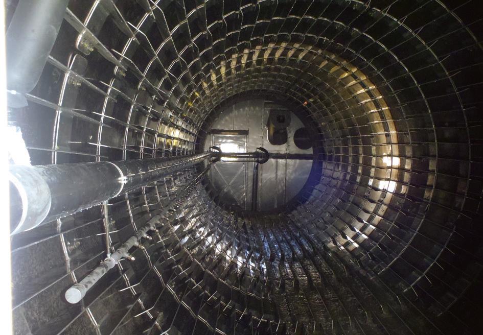
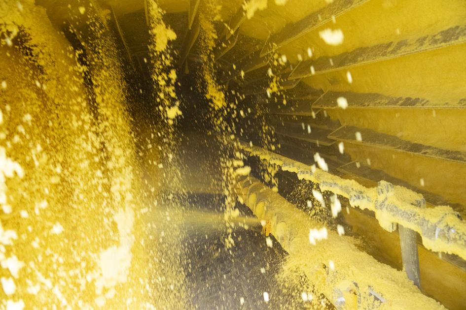
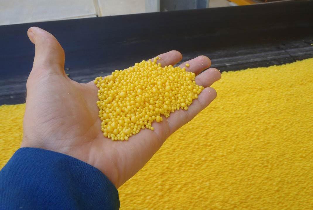
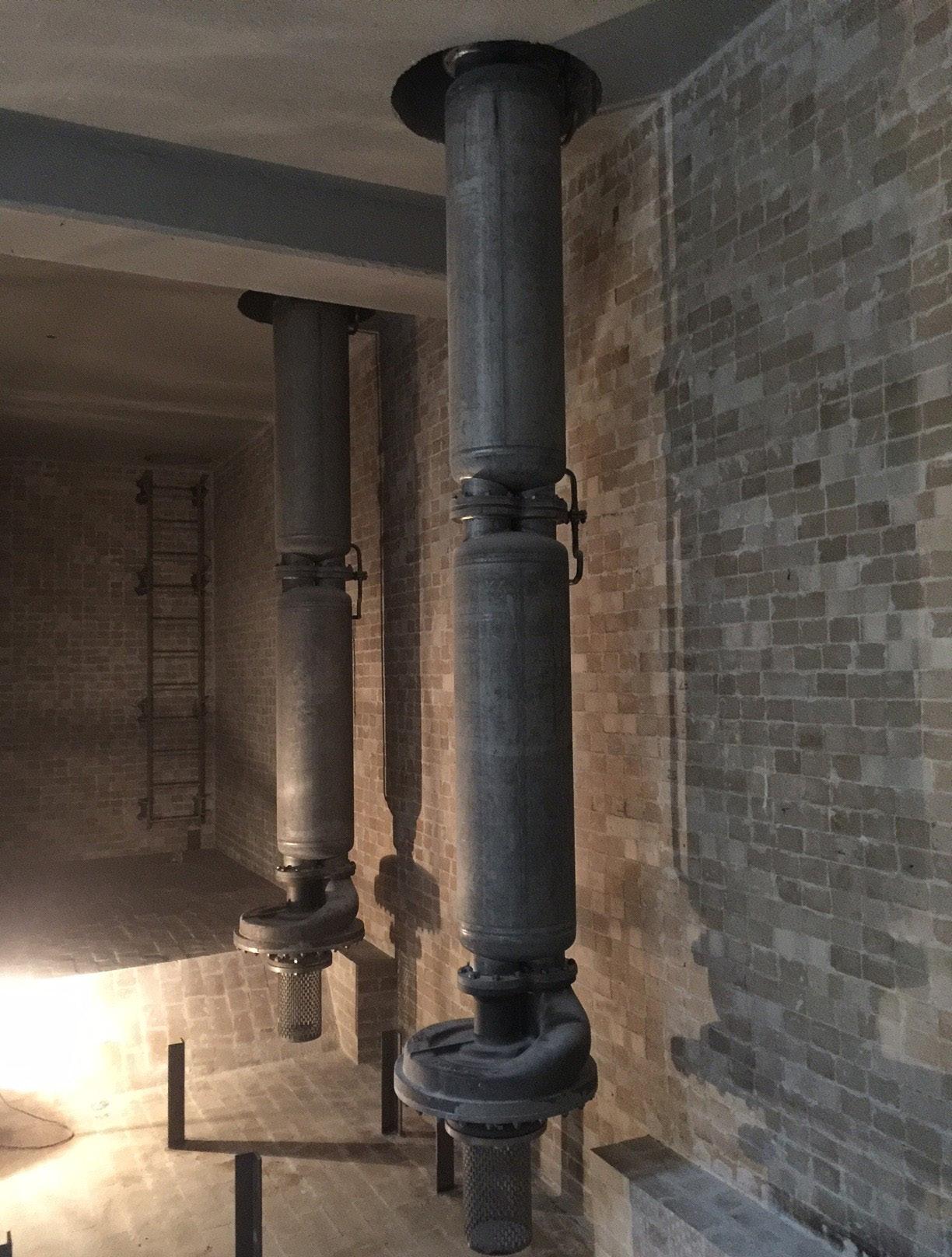
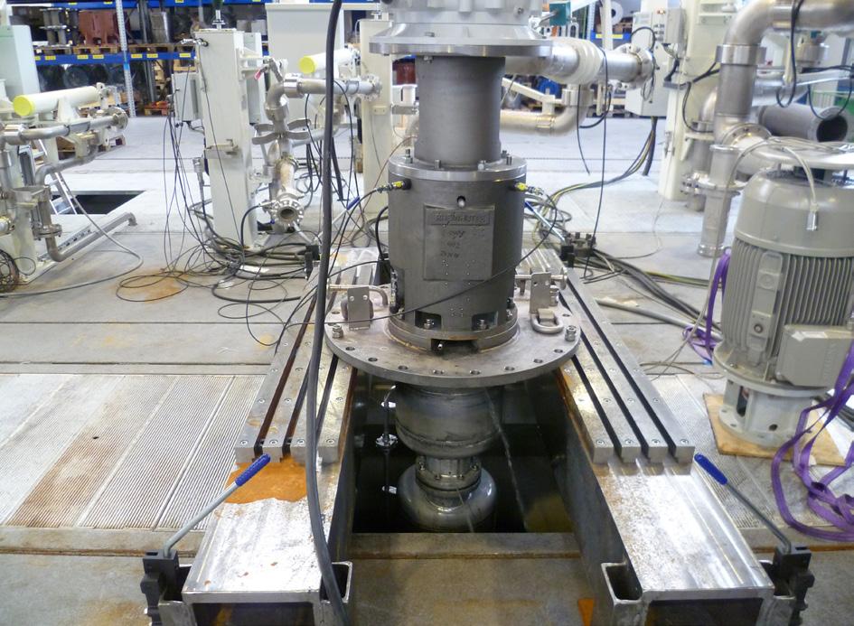
Michael Borchwaldt, ITT Rheinhütte Pumpen GmbH, explores how sulfur pumps in refineries can aid the desulfurisation process.
10 Digitalising the downstream
Miro Cavkov, EPC, Bulgaria, considers how digital transformation and artificial intelligence can boost operational efficiency and safety within the downstream industry.
15 Investing in a safer future
Emma Bundy, Yokogawa RAP, explores how industrial transformation solutions can improve safety, reliability, and operational efficiency for large corporations within the industry.
20 Time for a transfer
Richard Stambaugh, Merichem Technologies, analyses high performance mass transfer technologies and their viability as a treatment solution for refiners.
25 Drop by drop
Prashanth Chandran and Ralph H. Weiland, Optimized Gas Treating, Inc., examine the deployment of rate-based simulation and modelling in the design of liquid treaters.
30 Going against the grain
Varun Mathur, IPCO, provides insight into sulfur granulation technology in use at a refinery in Oman.
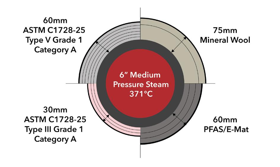
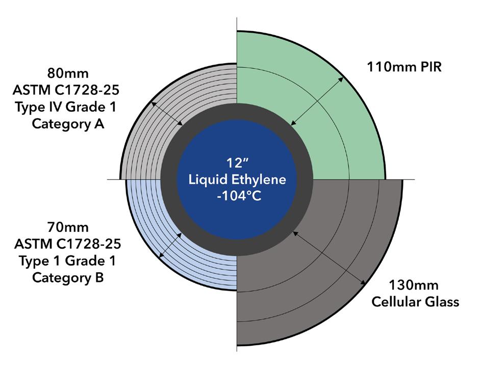
38 Insulating innovation: the evolution of industry standards
Mark Krajewski, Aspen Aerogels, USA, provides a specifier’s guide to best practices for designing with next-generation insulation materials.
45 Gas handling at LNG terminals
Rakesh Kulkarni, Burckhardt Compression, Switzerland, examines land-based compressors and how their performance can be improved.
49 Holistic hydrogen strategies
Brandy Johnson, Babcock & Wilcox (B&W), posits how embracing diverse hydrogen generation technologies and feedstocks can help adapt to emerging energy pressures.
53 Lasers for safety
Rhys Jenkins, Servomex, UK, considers how tunable diode laser technology can help overcome challenges in oxygen monitoring and measurement.
57 The case for cleaner combustion
Matthew Martin, ClearSign Technologies Corp., makes a case for why nitrogen oxides are a critical pollutant and outlines a strategy for emissions abatement.
61 Staged flare solutions
Esther Green, Zeeco Inc., USA, explores how staged flare solutions can reduce emissions and enhance flare performance.
This month’s feature article from Aspen Aerogels, a leader in aerogel technology, focuses on the critical role of the ASTM C1728 standard in guiding the use of flexible aerogel blanket insulation. With multiple types, grades, and categories now defined, the standard helps engineers match materials to application needs. The article reveals how seemingly minor substitutions can lead to major thermal losses, increased operating costs, and compromised system performance – making a deeper understanding of ASTM C1728 essential for anyone involved in insulation design, specification, and installation. Discover more at www.aerogel.com
ET Black™ Technology
Cut your CO2 emissions by 50% with the future of carbon black production
Compliant and innovative
Meets stringent environmental regulations, keeping your business future-ready
Unparalleled flexibility
Produce all ASTM grades and specialty grades seamlessly in a single plant
Sustainable Uses thermal decomposition of aromatic oils for cleaner production
CONTACT INFO COM MENT
MANAGING EDITOR James Little james.little@palladianpublications.com
ADMIN MANAGER Laura White laura.white@palladianpublications.com
CONTRIBUTING EDITORS Nancy Yamaguchi Gordon Cope
SUBSCRIPTION RATES
Annual subscription £110 UK including postage/£125 overseas (postage airmail). Two year discounted rate £176 UK including postage/£200 overseas (postage airmail).
SUBSCRIPTION CLAIMS
Claims for non receipt of issues must be made within 3 months of publication of the issue or they will not be honoured without charge.
APPLICABLE ONLY TO USA & CANADA
Hydrocarbon Engineering (ISSN No: 1468-9340, USPS No: 020-998) is published monthly by Palladian Publications Ltd GBR and distributed in the USA by Asendia USA, 701C Ashland Avenue, Folcroft, PA 19032. Periodicals postage paid at Philadelphia, PA & additional mailing offices. POSTMASTER: send address changes to HYDROCARBON ENGINEERING, 701C Ashland Ave, Folcroft PA 19032.
15 South Street, Farnham, Surrey
GU9 7QU, UK
Tel: +44 (0) 1252 718 999
OLIVER KLEINSCHMIDT DEPUTY EDITOR
Look around. It is highly probable that you can see at least one thing that has been derived from petroleum. Be it plastics, medication, or even beauty products, petroleum is everywhere. But why is that?
Oil has become the life-blood of humanity. It has become so essential to our society that if you were to remove every petroleum-based product from daily life then you’d set the entire human race back by a century.
Currently, it has been estimated that global oil consumption sits around 36 billion bbl/yr,1 with the biggest producers also doubling as the biggest consumers; a club that includes the usual suspects of China, Russia, Saudi Arabia, and the US.2 Considering this, estimates predict that at our current rate of global oil consumption we will have exhausted existing reserves in as little time as 47 years.1 That’s only two generations from now.
It’s not much time. So just how widespread is our use of petrochemicals?
Take, for instance, the daily life of an average person in the UK. They might drive to work or take the bus, but either way road transport alone makes up 57% of national oil consumption. Most petroleum is used as fuel for motor vehicles and this not only makes up a huge portion, but, of course, contributes to a rise in global emissions.
It does not simply stop there. Any job you work will see you interacting with dozens of things that would not exist as they are without petroleum. A significant portion of our world is made up of plastics – plastics derived from petrochemicals. Your phone, your computer, your pens, and even the laminated cover of this magazine uses plastics. Plastic is derived from a process called polymerisation which makes up the basic building blocks of most plastics, which can take many shapes and has been universally used due to how multifaceted it can be. Even in hospitals, you will see it being used not only for medical equipment – such as IV bags, heart valves, and artificial limbs – but also for actual medicines. Painkillers, antihistamines, and even antibiotics are synthesised from petroleum-based precursors.
Oil is an inescapable part of our lives. Clothing, beauty products, electronics, and even agricultural fertilizers all contain petroleum products in some form or fashion.3 It is so embedded in our society that its loss would result in massive, worldwide upheaval and change. This diversification explains exactly why countries like the US end up consuming over 20 million bpd of oil, making up 20% of total global consumption.2
But why does this matter?
Because petroleum, and the petrochemical sector as a whole, reaches far further than simple fuel consumption. Fuel for transport is the largest part but it is still only a part, and with fossil fuels being a limited resource, we have to be wary of our consumption. A shift in petrochemical usage is necessary not just because of the ecological impact, but because it is used for far more than fuel. We must prioritise these other uses for oil, or else risk going back to the dark ages.
1. worldometer, https://www.worldometers.info/oil/ [accessed 25 June 2025]
2. ‘What countries are the top producers and consumers of oil?’, EIA, https://www.eia.gov/ tools/faqs/faq.php?id=709&t=6 [accessed 25 June 2025]
3. ‘Oil in everyday life’, International Association of Oil & Gas Producers, https://www.iogp.org/ workstreams/advocacy/oil-natgas-in-everyday-life/ [accessed 25 June 2025]
NRU BEYOND THE
n CRYOGENIC GAS PROCESSING TECHNOLOGY
n CO2 , O2 & H2S REMOVAL
n MODULAR & EQUIPMENT FABRICATION
n RENEWABLE ENERGY SOLUTIONS
n FULL-SCOPE ENGINEERING & DESIGN
n CONSTRUCTION & INSTALLATION
BCCK has built its legacy on industry-leading nitrogen rejection (NRU) technology, setting the standard for performance and reliability. Our expertise extends far beyond NRUs, though—turbo-expander plants, acid gas pre-treatment, in-house fabrication of piping, pressure vessels, and skid assemblies, comprehensive engineering and design services, including debottlenecking, FEED studies, balance of plant engineering, I&E, and installation and construction—delivering cost-effective solutions across all project phases. BCCK combines technical innovation and best-in-class execution to go Beyond the NRU, providing critical solutions for the entire energy value chain, including renewables.
GUEST COM MENT
SARAH MILLER PRESIDENT & CEO, GPA MIDSTREAM
As the energy ecosystem continually evolves, the midstream sector is a constant. Midstream companies safely, responsibly, and expertly build and operate the infrastructure that quietly ensures our society’s energy needs are met – every hour of every day.
As President & CEO of GPA Midstream Association, I’ve seen how the commitment of our member companies to safety, reliability, and innovation assures satisfaction of society’s needs, including residential heating, electricity generation, transportation and cooking fuels, fertilizer, industrial manufacturing, and thousands of products we use in our daily lives.
The policy conversations about energy and climate present an opportunity. Demand for energy is growing. The application of renewable energy sources is technically challenging and expensive. Producing and delivering energy involves tradeoffs across dimensions of affordability, reliability, and sustainability.
While headlines often overlook midstream, society can’t function without it. Midstream enables society to cost-effectively meet energy demand and address climate and environmental issues. Indeed, midstream companies have helped reduce energy-related greenhouse gas emissions in the US while simultaneously delivering record oil and gas production.
maintenance to reduce emissions and address issues before they happen – real innovation with real impact.
Midstream professionals manage the pressures – literal and figurative – that move hydrocarbons safely from wellheads to end users while also innovating to minimise environmental and climate impacts.
This year’s GPA Midstream Convention – ‘Unveiling the Magic of Midstream Innovation’ – will highlight those advances. Our magic is not a sleight of hand, but technology-driven innovation that boosts efficiency, improves processes, and enhances safety.
Our magic is not a sleight of hand, but technology-driven innovation that boosts efficiency, improves processes, and enhances safety.
As the only trade association exclusively dedicated to midstream, GPA Midstream brings together engineers, operators, and policy experts from across our member companies to develop and promote the technical standards and best practices that keep pipelines and processing, compression, and storage facilities safely operating at peak performance. Our committees deliver solutions to real-world challenges – including emission detection and reduction. We make the industry better.
For example, member companies are deploying satellite-based leak detection and AI-driven predictive
It’s critical that we share our story with the public and with policymakers. GPA Midstream’s 'Let’s Clear the Air' consumer education campaign seeks to demystify midstream operations, highlight the value of midstream infrastructure, and show how midstream contributes to a high standard of living.
The convention offers three days of educational sessions and panel discussions. It’s an opportunity to engage in peer-to-peer problem solving, share case studies on emerging technologies, and hear from operators who’ve turned pioneering ideas into operational realities. Attendees will also discuss regulatory developments and explore how midstream remains resilient despite geopolitical uncertainties.
For many, a convention highlight is the collaboration that happens in the hallways and during roundtables – those conversations that confront a persistent challenge and deliver a fresh perspective. Attendees find colleagues who’ve solved similar puzzles and are willing to share solutions.
Join us in San Antonio, Texas, US, September 21 - 24, to help shape midstream’s next chapter.
THE WORKHORSE OF BLUE IS NAMED SYNCOR™
Maximize your mega-scale blue hydrogen and ammonia production with our SynCOR™ technology. Achieve more than 99% carbon recovery, unmatched efficiency, and the lowest levelized cost of hydrogen. Powered by our industrially proven autothermal reforming, SynCOR is a next-generation technology for today – and tomorrow.
Step into the future with SynCOR today!
WORLD NEWS
Malaysia | Woodside and PETRONAS eye long-term LNG supply
Woodside Energy and PETRONAS, through its subsidiary PETRONAS LNG Ltd, have signed a non-binding Heads of Agreement (HOA) for the supply of 1 million tpy of LNG to Malaysia from 2028 for a period of 15 years.
The LNG would be supplied from Woodside’s global portfolio and may include the recently approved Louisiana LNG project in the US.
The HOA reflects the shared ambition of both companies to formally commit to deepening cooperation across the LNG value chain, building a relationship of mutual trust, benefit, and success.
The agreement is expected to support PETRONAS’ efforts to ensure secure, flexible LNG supply to meet growing demand in Peninsular Malaysia and the broader Asia-Pacific region.
Brazil | Petrobas starts operations at the Paulínia Refinery
Petrobras has started operations at a new diesel hydrotreatment unit at the Paulínia Refinery (Replan), in São Paulo, Brazil.
The operation began three months ahead of the date originally scheduled in the feasibility study, and the project was executed within the approved investment level at the time.
With the start-up of the new unit, Replan increases its production
capacity of S-10 diesel by up to 63 000 bpd and jet fuel by up to 21 000 bpd. This expansion prepares the refinery for the phase-out of S-500 diesel, enabling the complete conversion of its diesel production to S-10 diesel. Additionally, this conversion improves the plant’s energy efficiency, reducing sulfur compound (SOx) emissions from the fleet, which will now use S-10 instead of S-500.
USA | EIA reports US refining capacity largely unchanged as of January 2025
According to the US Energy Information Administration’s (EIA’s) latest annual ‘Refinery Capacity Report’, US operable atmospheric distillation capacity, the primary measure of refinery capacity, totalled 18.4 million bbl per calendar day (bpcd) on 1 January 2025 – essentially flat compared with last year.
In 2025, the three largest refiners in the US – Marathon, Valero, and ExxonMobil – all reported calendar day capacity increases of less than 1% compared with 2024. These changes likely stem from small scale process improvements, rather than major capacity expansions, unlike previous years. No major refinery expansions or transactions occurred from January 2024 through January 2025, unlike in 2023 when a handful of major projects were completed, including a significant expansion at ExxonMobil’s Beaumont, Texas, US, facility.
UAE | Wood secures significant EPCm contract to expand ADNOC Gas Habshan facility
J
ohn Wood Group PLC (Wood) has been awarded a US$2.8 billion contract by ADNOC to deliver an engineering, procurement, and construction management (EPCm) package for the long-term gas processing facilities at the UAE’s Habshan facility.
The contract value includes pass through revenue, with Wood anticipated to recognise US$400 million of revenue through EPCm services.
Wood’s scope includes the delivery of substantial upgrades and debottlenecking solutions to the existing Habshan and Habshan 5
gas processing mega-complexes and pipelines, including brownfield modifications and the installation of new facilities.
The Rich Gas Development (RGD) project will increase efficiency and modernise the facility to support increased gas output from ADNOC’s upstream expansion. Habshan is one of the largest gas process complexes in the world.
Ken Gilmartin, CEO at Wood, said: “ADNOC Gas’ RGD programme is pivotal to the UAE’s energy security strategy and broader economy. We’re proud to be at the heart of such a significant initiative.
“ Wood gained extensive knowledge of Habshan delivering the front-end engineering design and we will deliver the EPCm phase while the facilities remain fully operational in order to sustain critical gas supply.
“ This win reinforces our position as a leader in highly complex engineering and project delivery solutions at considerable scale.”
The project will be delivered by more than 500 Wood engineering, project management, and commissioning specialists based in Abu Dhabi with support from the company’s global engineering hubs.
WORLD NEWS
DIARY DATES
25 - 28 August 2025
AFPM Summit Grapevine, Texas, USA summit.afpm.org
09 - 12 September 2025
Gastech Milan, Italy www.gastechevent.com
16 - 18 September 2025
Turbomachinery & Pump Symposia Houston, Texas, USA tps.tamu.edu
18 September 2025
TSA Tank Storage Conference and Exhibition Coventry, UK tankstorage.org.uk/conference-exhibition
21 - 24 September 2025
GPA Midstream Convention San Antonio, Texas, USA www.gpamidstreamconvention.org
23 - 25 September 2025
1st Annual Aboveground Storage Tank Conference & Trade Show
Long Beach, California, USA www.nistm.org
20 - 23 October 2025
API Storage Tank Conference & Expo Phoenix, Arizona, USA events.api.org/2025-storage-tank-conference-expo
03 - 06 November 2025
ADIPEC
Abu Dhabi, UAE www.adipec.com
17 - 20 November 2025
ERTC Cannes, France worldrefiningassociation.com/event-events/ertc
09 - 11 December 2025
18th Annual National Aboveground Storage Tank Conference & Trade Show
The Woodlands, Texas, USA www.nistm.org
France | BASF starts up hexamethylenediamine plant in France
BASF has announced the startup of its new world scale hexamethylenediamine (HMD) plant in Chalampé, France, construction of which began in 2022.
The plant increases BASF’s annual HMD production capacity to 260 000 t.
“This investment underlines BASF’s strong commitment to chemical production in Europe and our determination to support regional growth. It is yet another example of how we put our ‘Winning Ways’
strategy into action to create long-term value for our company and secure our future competitiveness in a volatile economic environment,” said Dr Stephan Kothrade, member of the Board of Executive Directors of BASF.
The plant is an essential component of BASF’s strategic path forward in its polyamide (PA) 6.6 business in Europe. In addition to starting up the new HMD plant, the company is in the final stage of expanding its PA 6.6 production in Freiburg, Germany.
Malaysia | Pengerang Energy Complex boosts Asia’s petrochemical supply chain
The Pengerang Energy Complex (PEC) has leveraged the Pengerang Deepwater Terminal (PDT) to boost Asia’s petrochemical supply chain.
The upcoming PEC is strategically integrated within the Pengerang Integrated Petroleum Complex (PIPC), aligning with Malaysia’s Economic Transformation Programme in support of the nation’s ambitions to become a
regional hub for oil, gas, and petrochemicals.
PEC looks to leverage the direct proximity and connectivity to the PDT, a next-generation port and storage facility that has been operational since 2014 and is recognised as the first project of its kind in Southeast Asia.
PDT is a naturally sheltered deepwater facility located along key shipping routes in Southeast Asia.
USA | Neste extends SAF fuel supply to Ontario International Airport
Neste has reached an agreement with Amazon to provide 7500 t (2.5 million gal.) of neat Neste MY Sustainable Aviation FuelTM for its Amazon Air cargo operations at San Francisco International Airport and Ontario International Airport in California, US, through to the end of 2025.
This agreement makes Amazon the first company to purchase and use sustainable aviation fuel (SAF) at Ontario International Airport,
ranked among the top 10 cargo airports in the US.
Amazon has made an ambitious commitment to reach net zero carbon emissions across its global operations by 2040, and adopting SAF is a key lever to decarbonise its air cargo operations. The agreement to use SAF in California is part of a broader cooperation between Amazon and Neste that started four years ago when Neste delivered SAF to Amazon at Cologne Bonn Airport in 2021.
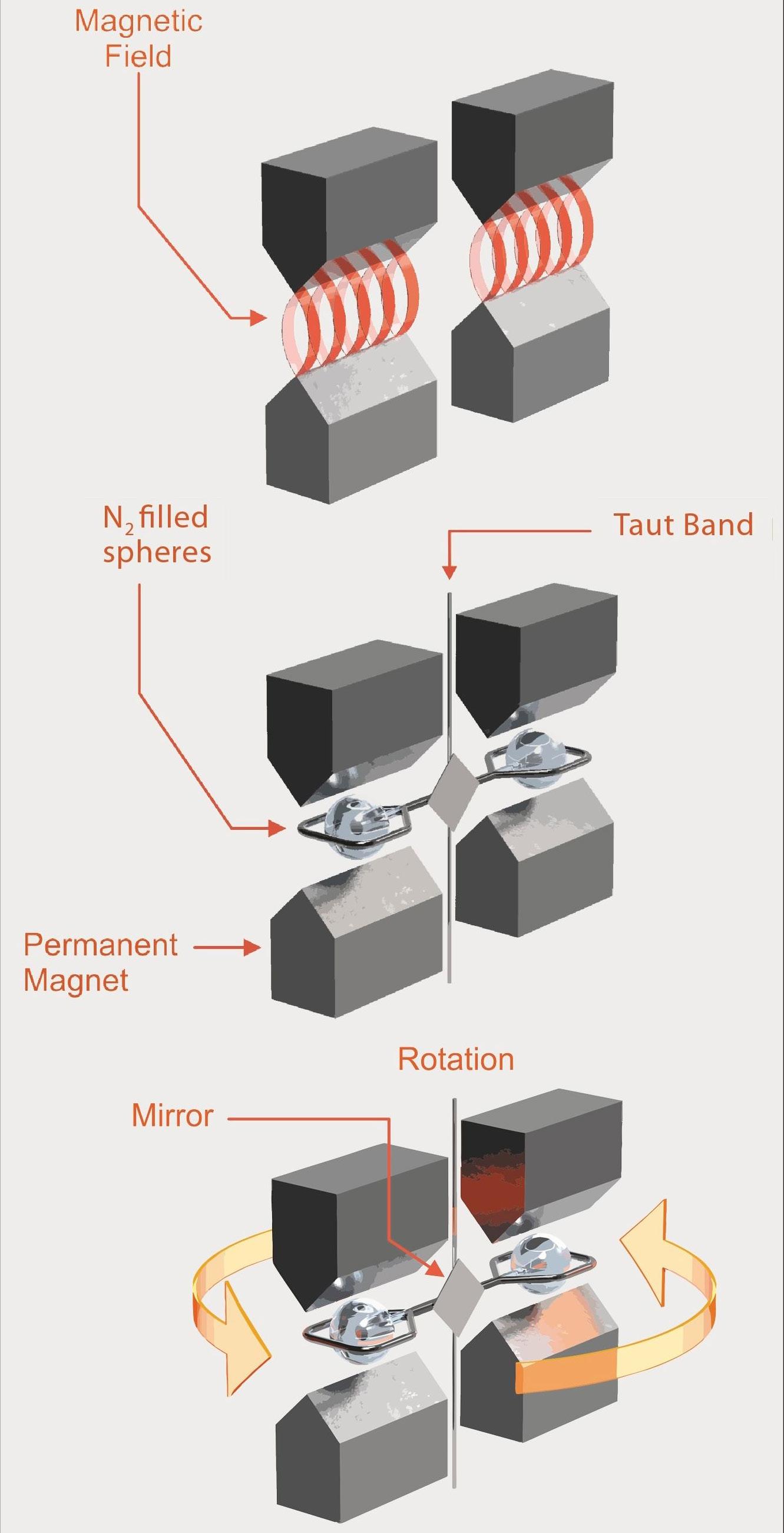
Introducing MagAFS, our latest breakthrough in Advanced Filtration System (AFS) technology. Designed for unmatched nano-particle removal, MagAFS utilizes patented magnet technology to efficiently remove solids from gas and liquid streams – protecting catalyst beds and optimizing performance.
1. Ferromagnetic Materials
Iron-containing particulates, Iron Sulfides, Coke fines
2. Paramagnetic Materials
Manganese, Chromium, Cerium, Potassium, Vanadium, and their oxides and sulfides
3. Diamagnetic Materials
Diamond, Graphite, Sand, Alumina, Bismuth
Miro Cavkov, EPC, Bulgaria, considers how digital transformation and artificial intelligence can boost operational efficiency and safety within the downstream industry.
In today’s volatile and efficiency-driven market, digital transformation is no longer optional – it is a core enabler of resilience and profitability in the refining sector. Across the entire refinery ecosystem, artificial intelligence (AI), real-time optimisation (RTO), and digital twin technologies are redefining how operators manage complexity, reduce emissions, and improve yields.
AI in refineries: artificial or applied intelligence?
When considering AI in refining, is this really something that is ‘artificial?’ Or is it more accurate to describe it as applied intelligence – a natural evolution of decades of scientific development, engineering mastery, and continuous technological innovation?
The downstream industry is anything but artificial. It is built on generations of accumulated expertise, rigorous chemical
engineering principles, academic research, and applied research and development (R&D). Every model, simulation, and control system used in today’s refineries is grounded in hard science. What modern AI brings to this equation is not artificiality but rather computational power, real-time decision support, and the ability to scale decades of knowledge across complex operations.
In that sense, AI in refineries is applied intelligence – the ability to harness existing know-how, feed it with real-time data, and turn it into actionable insights that drive performance.
The real value of AI in refining: intelligence applied in real-time
In today’s high-pressure, fast-evolving energy environment, decisions cannot wait. Feedstock prices, policy shifts, and market demands are changing in real time. This is where AI
steps in – not to replace human decision-makers, but to supercharge their ability to make the right call, faster and more precisely.
n AI enables ‘what-if’ scenario planning that simulates countless operational pathways, helping teams choose the optimal one based on live refinery data.
n It offers visibility into unit-level behaviour and system-wide performance, adjusting process parameters for different crude blends or product-focused regimes.
n By doing so, AI delivers greater molecule control, allowing refineries to unlock higher-value outputs from complex feedstocks.
And this is not just theory – leading technology providers now consistently report up to 5% gains in energy efficiency, throughput, and yield quality when the right digital tools are in place.
This article will explore how digital transformation and AI are essential within refineries, and how they can yield up to 5% more precise results – ultimately strengthening the entire refinery ecosystem.
Key areas for digital transformation in refineries
Process optimisation and control:
rethinking
the heart of refining
AI-driven advanced process control (APC), real-time analytics, digital twins in crude and process heaters, CDU/VDU units, FCC, hydrocrackers, and reformers can increase yield efficiency through predictive optimisation, alongside reducing variability and enhancing operational stability under dynamic conditions. At the heart of every refinery is a foundational operation: crude distillation. And at the very start of this process lies the
generation of heat and energy – historically achieved through combustion in crude and process heaters. For decades, fuel oil has served as the go-to energy source. But in an era of tightening emissions regulations, rising fuel costs, and mounting sustainability expectations, this legacy approach is no longer viable.
The imperative is clear: it is time to reinvent how refineries produce and manage process heat.
Modern process optimisation begins not with downstream systems – but with the heaters themselves. Specifically, in the radiant and convection sections, tremendous potential exists to enhance combustion, heat distribution, and thermal efficiency. Today’s technologies enable refiners to fine-tune these parameters with unprecedented precision.
As part of the industry’s broader push toward decarbonisation, a shift away from traditional fuels toward a new energy mix is being witnessed:
n Natural gas, sometimes blended with hydrogen, offers a transitional, lower-carbon fuel with a reduced emissions footprint.
n Lower-carbon fuels (such as mid-distillates) may still be viable in niche applications, though cost and long-term sustainability present challenges.
n Electrification allows for pinpoint temperature control, reducing inefficiencies like hot and cold spots.
However, technology alone is not enough. To truly maximise efficiency and sustainability, refiners must adopt applied intelligence – the strategic application of AI-powered monitoring, predictive analytics, and APC. These tools process millions of data points in real time, identify hidden inefficiencies, simulate optimal operating conditions, and automatically adjust key variables.
In this new era, heaters are no longer passive components – they are smart assets, capable of adapting and optimising themselves in response to shifting feedstocks, demand signals, and regulatory pressures. Elevating their performance is no longer a technical enhancement – it is a strategic imperative for refineries looking to remain competitive, compliant, and future-ready.
Predictive maintenance: from breakdown response to intelligent reliability
Machine learning (ML) models monitor vibrations, temperature, and pressure in rotating equipment (such as compressors and pumps) and heat exchangers which can reduce unplanned downtime by up to 30%, extend equipment life, and lower maintenance costs.
In complex and high-pressure refining operations, equipment uptime is not just operationally important – it is mission-critical. Unplanned failures can cost millions, disrupt supply chains, and compromise safety. That is why predictive maintenance, enabled by AI and real-time analytics, is fast becoming a foundational pillar of refinery reliability.
Unlike traditional maintenance strategies that rely on fixed schedules or reactive fixes, predictive maintenance leverages ML to continuously analyse key indicators – like vibration patterns, temperature shifts, and pressure deviations
– across critical assets. From rotating machinery and compressors to heat exchangers and pumps, AI tools monitor health trends and can detect early warning signs before failure occurs.
But this is about more than just avoiding breakdowns. It is about transforming maintenance into a connected, intelligent function:
n Shared dashboards and real-time alerts break down silos between operations, engineering, and maintenance teams.
n Cloud-based systems ensure everyone has access to the same actionable insights, whether they are in the control room or in the field.
n AI-optimised schedules help teams prioritise maintenance during optimal windows, improving resource allocation and plant safety.
The result? Higher asset availability, smarter resource planning, and fewer emergency shutdowns. Predictive maintenance does not just save time and money – it brings confidence and coordination into daily refinery operations.
In an environment where every hour of uptime matters, AI-enabled predictive maintenance is not a luxury – it is a strategic edge.
Energy management: turning efficiency into a competitive advantage
AI and digital twins offer real-time monitoring, load optimisation, and emissions tracking in boilers, furnaces, utility systems, and steam networks. This can cut energy costs by 5 - 15%, reduce emissions, support decarbonisation goals, and optimise utility balances across fluctuating demand.
Energy is one of the largest operating costs in a refinery – and one of the biggest opportunities for transformation. With decarbonisation mandates tightening and energy prices remaining volatile, the pressure is on to do more with less. That is where AI-powered energy management systems come into play.
By deploying real-time monitoring and digital twin models, refineries can simulate entire energy systems – from steam and power distribution to individual boilers and furnaces. These tools provide visibility not just into usage, but into inefficiencies that would otherwise go unnoticed.
With AI in the loop, refiners can:
n Dynamically balance energy loads, reducing overconsumption and peak demand charges.
n Predict and prevent energy losses by identifying suboptimal performance in equipment.
n Continuously optimise fuel mixes for both economic and environmental goals.
Energy becomes not just a cost to manage, but a strategic lever. And with integrated emissions tracking, these systems also support environmental, social, and governance (ESG) targets – making regulatory compliance smoother and more transparent.
In short, energy management is evolving from manual balancing to intelligent orchestration – and the refineries that embrace this shift are gaining a measurable edge.
Revamp to thrive in the new reality
Ever-changing market conditions, global economic challenges, and the shared journey of the energy transition all mean it is crucial to evaluate easy-to-implement and costeffective improvement opportunities. At Shell Catalysts & Technologies, our solutions open new possibilities for smarter investments while preserving cash through revamping, reconfiguring, or optimising your existing assets. Our experts co-create tailored solutions while keeping your margins in mind – ensuring the investments you make right now can help you maintain your competitive advantage into the future.
Learn more at catalysts.shell.com/revamps.
Planning and scheduling: smarter decisions, smoother operations
AI-enhanced tools can be used for planning simulations, scenario modelling, and real-time adjustments in crude selection, blend optimisation, and product slate management. This can boost margins by up to US$00.50/bbl, alongside enhancing agility to adapt to market shifts and improve coordination across supply, operations, and sales.
Refining is a margin game – and the winners are the ones who can respond to change with speed and precision. Whether it is a shift in crude quality, a sudden market swing, or a weather disruption, today’s planners need tools that go beyond spreadsheets and static models.
Modern planning and scheduling platforms, powered by AI and advanced simulations, allow teams to forecast outcomes, test scenarios, and align production with real-world constraints – all in real time.
These platforms enable:
n Crude-to-product modelling to optimise feedstock selection based on economics and operational limits.
n Integrated scheduling that syncs production with logistics, storage, and downstream demand.
n Automated plan reconciliation when deviations occur, ensuring minimal disruptions.
AI helps planners not just react faster – but plan smarter. It is about seeing the full picture: economic, operational, and environmental. And with data-backed insights, teams can make confident decisions that boost margins, reduce waste, and improve product delivery. As complexity grows, traditional planning just cannot keep up. With intelligent planning and scheduling, refineries can turn volatility into opportunity – and execution into a competitive strength.
Digital twin implementation: innovate without interrupting
Real-time virtual replicas of physical assets and processes in entire refinery systems or high-impact units like CDU, FCC, or reformers can offer benefits such as:
n Safely simulate upgrades, operational changes, and new configurations.
n Identify inefficiencies, constraints, and performance opportunities.
n Reduce risk and streamline transitions to new technologies.
In a refining landscape where change is constant and risk tolerance is low, digital twins are emerging as the ultimate decision-making tool. These intelligent virtual replicas bring physical operations to life-mirroring equipment, processes, and performance in real time. But they are not just for monitoring. They are for experimenting, optimising, and innovating – without ever touching the actual plant.
With a digital twin, refineries can:
n Simulate operational changes and test various scenarios under real-world constraints.
n Trial new technologies like carbon capture or co-processing before physical rollout.
n Predict how different feedstocks or configurations will impact throughput, yield, or emissions.
This gives teams the confidence to make bold decisions, because they have already seen the outcomes. And when start ups or changeovers happen, digital twins help smooth the path, reducing trial-and-error downtime and de-risking the unknown.
The value becomes even clearer when tackling decarbonisation goals. Whether it is integrating hydrogen, reconfiguring energy networks, or testing carbon reduction strategies, digital twins reveal the most effective paths.
In short, a digital twin turns a refinery into a living lab. It enables smarter, data-driven decisions that accelerate progress while protecting operations. And in an industry where time, energy, and precision matter, that is more than a digital tool, it is a strategic advantage.
Workforce enablement: empowering people in a digitally connected refinery
Multi-platform dashboards, mobile-first interfaces, AR/VR-based training, and digital workflows in control rooms, maintenance zones, and safety operations can help to close skill gaps and standardise best practice, which enables faster, smarter decisions with real-time data and context, alongside facilitating remote collaboration and troubleshooting.
Today’s refinery workforce demands more than clipboards and handwritten logs. Legacy tools are giving way to real-time, mobile-first platforms that keep teams informed, aligned, and responsive – whether in the control room or out in the field.
Digital dashboards, mobile ticketing, and standardised work instructions replace outdated methods with speed, clarity, and accountability. AR/VR training accelerates onboarding and improves safety by simulating complex procedures in a hands-on, repeatable way.
Enabling the intelligent refinery
Digital transformation is no longer optional – it is essential. As operations grow more complex, intelligent and connected refineries are emerging as the key to profitability, resilience, and sustainability. By moving beyond siloed processes to real-time, AI-powered platforms, refiners can unlock efficiencies, improve decision-making, and empower teams across every layer of the plant.
The real barrier is not data – it is timely computation. AI tools now turn raw data into real-time insights, driving predictive maintenance, yield optimisation, and emissions reduction with speed and precision.
So, is it AI being deployed or are operators applying the intelligence that has always been there?
With the right tools, AI becomes more than a buzzword. It becomes applied intelligence – turning expertise, data, and science into a smarter, faster, and more competitive downstream facility.
Emma Bundy, Yokogawa RAP, explores how industrial transformation solutions can improve safety, reliability, and operational efficiency for large corporations within the industry.
Downstream operations are crucial for transforming raw hydrocarbons into usable products that meet market demands and environmental standards. With the increasing accessibility of technology, advanced solutions such as safety software, automation, and data analytics are being more widely integrated into downstream processes to improve safety, enhance efficiency, and reduce operational costs.
Figure 1. Moving to a digital system offers a safer path to the future.
As global energy demands evolve, the adoption of smart technologies is becoming essential for downstream operators to remain competitive, compliant, and environmentally responsible.
The industrial transformation software market has recently experienced considerable growth and consolidation, driven by the escalating demand for smarter, safer solutions and a broader adoption of Industry 4.0 (digital transformation).
Positive momentum alongside a consistent upward trend have intensified competition, resulting in a surge of acquisitions, investments, and asset sales associated with digital transformation software.
Considering the above-mentioned factors, embracing an Industry 4.0 future was always going to be inevitable, and the transition from legacy control of processes and information is expected to accelerate further in the coming years.
What are industrial transformation solutions?
Industrial transformation solutions are designed for operational improvement, safety, and asset reliability in large corporations seeking to improve the effectiveness of industrial transformation programmes using innovative technologies.
Implementing these solutions enables companies to fully embrace industry 4.0 through streamlining operations, mitigating risks, and proactively preventing undesired events, ultimately saving time, resources, and, most importantly, injury and fatalities.
How do you identify what type of solution will work best?
There are lots of options on the market, but the key is to adopt those options that best suit the current infrastructure and legacy systems of the business.
Also important is to work with a provider who facilitates a tailored approach, ensuring successful implementation and long-term benefits. By digitising work processes and automating workflows to suit the business and its sites, companies can significantly enhance overall productivity, providing a business with a robust digital platform to build on for the future.
It is important when considering which technologies to adopt to ensure the future sustainability and adaptability of the technologies and their interoperability with other site systems going forward. It is only with this outlook that companies will start getting proper return on investments (ROIs).
Barriers to change
Choosing the right partner and technology is not the only step that needs to be considered in a digital transformation journey and its consequent ROI. For the workforce, change can be daunting, and the longer they become used to a particular way of working, the harder it can be to change.
This concern is often a fear of starting the journey, which may be born from:
n Past experiences.
n Fear of having to learn new things.
n Fear of widening responsibility beyond a few key people.
As previously mentioned, a good digital system is about offering a more intelligent way to manage what is already being done and, in so doing, gaining all the advantages that this brings to safe working and optimisation of processes.
Moving to a digital system offers a smoother path into the future because the rules and regulations will change over time, and safety systems must also change to keep up with the times.
Digital systems offer the easiest way to keep up and maintain version control.
Another area of potential concern is where companies only have a small number of access rights to the system. This tends to result in a barrier between the general workforce and the people who are assigned access to the system.
Good integrated safe systems of work (ISSOW) should be role-driven and allow the broadest level of access possible so everyone who needs to be involved in safe working processes, including contractor workers, can be.
This helps to foster a much more inclusive culture and by everyone having their own access and rights, companies are doing their utmost to ensure that a robust system is in place, with each person being accountable in line with the competence assigned to them by their roles.
A best practice workflow, and an intuitive, easy-to-use interface will take away most fears and ensure ease of adoption and allow a swifter take-up, enabling companies to quickly experience the benefits that digital transformation can offer.
How do digital systems achieve a step-change in safety?
There really should not be any difference at a fundamental level. Both paper and digital systems ensure that all the safe working factors are implemented, including local site, national, or international rules.
However, not all digital – or indeed paper – systems are created equal. A good digital system should offer users a more intelligent way to manage safe working practices.
Any ISSOW should ensure that all the information is shown in the most visible and consistent manner possible. The great advantage of digital systems is that they can offer a degree of detail that is not possible in paper-based systems.
They offer a more intelligent solution in several ways:
n Competence controlled work.
WE’RE COMMITTED TO PROTECTING YOUR PROFITS
Our solutions help you keep moisture out of your process
Controlling moisture is essential for product quality and process optimization. Unchecked, moisture can reduce process yields, damage valuable equipment, and increase downtime.
That’s why it’s critical to accurately measure moisture levels in process gases. The right reading depends on selecting the proper technology, along with the correct sample handling system, for the application. With decades of expertise and a wide range of technologies, AMETEK has the full-spectrum moisture monitoring solution to meet your application requirements.
n Lessons learned and updates are easier to apply.
n They can incorporate intelligent questions that apply filters to remove spurious items.
n They can incorporate a knowledge base to help with risk assessments.
n They can automatically tie isolations to permits to ensure that permits cannot be released without isolations being in place, and that isolations cannot be removed until all permitted activities are complete.
n They can link to monitoring activities such as post-issue monitoring, fire watches, and monitoring of defeats.
n They can provide better visibility of work, covering exclusions, and potential simultaneous operations (SIMOPS) far more easily.
An effective digital safe system of work is not just about taking a paper system and converting it to digital forms because, whilst some efficiency is gained, the only thing that is optimised is that the route to an incident becomes faster.
Effective digital systems, such as Yokogawa’s RAP4 software – part of the overall OpreX TM Control of Work offering – allow users an easier-to-manage system that enhances the good work they are already doing by enabling workers to concentrate on what really matters, through removing all those items that are unnecessary for the work at hand.
Paper systems simply cannot do this, which means the process of permitting can only be optimised to a certain point before the next logical step in the continuous improvement process, which must be the digitisation of the system.
How do digital systems achieve expedient ROI
Many of the easy gains from Industry 4.0 have already been achieved, but one area that has lagged behind somewhat is safety. The reason is perhaps that while everyone will agree that safety is critical, the benefits are harder to visualise from a financial perspective.
However, there are many areas that expedient ROI can be achieved when safety software is successfully implemented and embraced by the workforce:
n Optimised workflows for better collaboration, improved productivity, and accuracy.
n Real-time visibility of work ensuring SIMOPS risks are minimised.
n Improved communication capabilities between all workers and the control room.
n Significantly improved upfront planning capabilities, saving both time and cost.
n Improvement actions can be quickly implemented, closing the loop on safety.
n Facilitation of continuous improvement initiatives across the business.
n Significantly improves audit capability whenever it is needed.
n It can bring both workforce and contractors together under one safe system.
n Connectivity to legacy systems and future technologies allowing interoperability.
Having access to all of this not only improves the safety of the site and workforce, but also the efficiency with less overburdening of resources, alongside fewer postponements, delays, and incidents.
And when the digital transformation initiatives are driven directly from the top and become a fundamental way of working, it leads to greater uptime and enhanced profitability, extending benefits well beyond the initial ROI and empowering the business to drive a prominent transformation in worker safety performance.
Smarter, safer working
Work process optimisation is all about smarter, safer working. Yokogawa’s OpreX Control of Work solutions can make a real difference in helping companies to achieve the cultural and system improvements necessary to truly achieve robust, repeatable, and consistent safer working practices, and to enable real optimisation of working processes without risking worker safety.
Whilst changing to a digital system from whatever plants have at present – be that paper, older electronic systems, or a mixture of the two – can be an issue for concern, a capable system and the benefits that can be gained by implementing its modules will enable a critical foundation of safety for the future.
The future
Industry 4.0 is here, and the focus is now shifting toward Industry 5.0, which emphasises placing people at the centre of operations. This shift highlights the importance of prioritising the safety and wellbeing of the workforce across industry, with emerging technologies like drones and robotics playing a crucial role in ensuring successful and secure outcomes.
Figure 2. Work process optimisation is all about smarter, safer working.
Richard Stambaugh,
Merichem
Technologies, analyses high performance mass transfer technologies and their viability as a treatment solution for refiners.
Finding chemical processes bypassing raw material purification and product separation is extraordinary. Most reactions require some degree of refinement and separation for efficiency and purity. In the oil and gas industry, hydrogen sulfide (H2S) and mercaptans found in crudes must be removed from intermediate or final products for performance, economic, environmental, and health reasons. In many cases, mass transfer is the foundational solution in identifying and optimising processes for separation and refining.
Mass transfer
There are repositories full of technical literature on commercial processes for impurity removal, but not all treatments are created equal, and not all treatment offerings using mass transfer as the solution can be trusted to function the same. It has created a challenge in identifying and selecting the optimum treatment for removing impurities from hydrocarbon streams.
Conventional dispersion and phase separation methods are affected by significant shortcomings. The conventional method of contacting two immiscible liquids is to disperse one liquid thoroughly into the other as small droplets. Where small droplets are generated using high differential pressure mix valves, larger droplets are formed using trays or packing. Impurities pass between the two phases at the surface of the droplet. Even when the dispersion-based system provides adequate treatment, separating the two phases is usually inefficient. The smaller the droplet size, the more separation time is required. Since the separation drum has a fixed volume, increasing the quantity of smaller, micron-sized droplets to improve mass transfer results in insufficient time to separate fully. Thus, the micro-droplets carried over with the treated hydrocarbon phase cause minor to moderate contamination in downstream equipment. If the shear force is set too high across the mixing device to force more mass transfer, stable emulsions can form, resulting in massive carryover out of the separator vessel. The resulting contamination downstream can be difficult to remove.
In this scenario, mass transfer can only be improved by creating more numerous and smaller droplets to increase the surface area. This same treating goal, however, is more effectively accomplished using non-dispersive hydrocarbon treating processes for caustic, amine, and acid.
State of the mass transfer market
Research firm Market Research reported late in 2024 that the mass transfer market is expected to grow substantially over the next few years, due to an increasing demand for purified substances in various industries, including petrochemicals and refining, where there is a need to separate and purify crude and gas. The analyst firm also calls out
aggressive research and development for innovative techniques expected to revolutionise the mass transfer industry. Continuously evolving regulations and standards related to the use of environmentally friendly and energy-efficient mass transfer systems on federal and state levels are also driving market growth.
A technology solution
There is a highly adaptable, non-dispersive mass transfer device that utilises caustic, amine, and other aqueous solutions as the treating reagent to remove acid gases, mercaptan compounds, and other aqueous-soluble impurities from liquid and gas hydrocarbon streams. It consists of a vertical cylinder packed with thousands of metallic fibres, also known as a ‘fibre bundle’. The hydrocarbon needing treatment and the aqueous treating solution are introduced to the top of the bundle and flow co-currently through the bundle.
As both phases flow down the bundle, the aqueous phase adheres to, or wets, the metal fibres and is continually renewed as it flows down the length of the fibre via a combination of gravity and interfacial drag between the two immiscible phases. The hydrocarbon phase flows through the cylinder co-currently and between the aqueous-wetted fibres. The large surface area and tight packing of the metal fibres bring ultra-thin falling films of the aqueous phase into intimate contact with the hydrocarbon phase. The interfacial surface area produced is orders of magnitude larger than in conventional droplet-dispersion devices, allowing impurities to diffuse easily between phases.
After the mass transfer is completed, both phases enter a separator, quickly allowing complete phase separation using their density difference. Due to the lack of microdroplets, bulk separation takes only a few minutes.
This technology has many benefits. The large interfacial surface area, the microscopic diffusion distance, and the continuous renewal of the aqueous phase of this technology, combine to yield mass transfer efficiencies greater than possible with conventional dispersive treatments. Because it is highly customisable, fibre bundle geometry allows the treatment of a wide range of hydrocarbon types with different physical properties. The inherent low differential pressure drop across the fibre bundle and the fast phase separation time facilitate the retrofit of this treatment process into existing systems as a debottlenecking solution. The co-current flow is more forgiving during hydrocarbon flow upsets, allowing treatment even under sub-optimal conditions. Carryover is virtually eliminated due to the avoidance of droplet formation as the aqueous phase adheres to the fibres in the contactor, rather than being dispersed into the hydrocarbon phase. Emulsion formation is also effectively eliminated. Since efficient phase contact occurs without dispersion, stable emulsions rarely form in the unit.
Similarly, the system does not depend on gravity settling for microdroplets or emulsion coalescence, which greatly reduces separation time. Processing vessels can be much smaller. In most cases, expensive downstream coalescers and other clean-up equipment are not required, although coalescers can further enhance the separation, taking the ultimate separation down to almost non-detectable levels of carryover of aqueous treating liquids in the hydrocarbon product. The use of smaller separators translates to less expensive equipment cost, and with fewer
pieces of smaller equipment, plant space is more efficiently utilised. Most importantly, this method of mass transfer achieves maximum removal of impurities from the hydrocarbon to meet today’s stringent standards as set forth by the US Environmental Protection Agency’s (EPA) Clean Air Act.
The challenges of other solutions
Conventional caustic treating processes with dispersive mixing devices and phase separation were once the only option available to the industry. However, conventional dispersion and phase separation methods are subject to numerous shortcomings, including lack of turndown capability, plugging, flooding, channelling, unpredictable treating results, long settling times, aqueous phase carryover, generation of dilute aqueous wastes, lower service factor, hydrocarbon losses, larger equipment leading to increased plot space requirements, product contamination, and additional processing steps and equipment are needed to separate phases.
Separating the two phases can be problematic even when the dispersion-based system provides adequate treatment. The mixture must remain in the phase separator until the caustic droplets settle out by gravity, which can take hours. As the treating requirement becomes more stringent, mixing energy is increased to maximise interfacial surface area, leading to greater aqueous phase dispersion and significantly longer separation times.
Stable emulsions can form in the mixing device, resulting in massive carryover from the separator vessel. Due to excessive carryover, expensive equipment such as knockout vessels, sand filters, and water wash units must be installed downstream to remove the dispersed aqueous phase from the treated product. Treatment is often interrupted if an emulsion develops. Excessive emulsion formation can damage downstream equipment and foul separators and other mass transfer equipment.
The treating processes
Merichem Technologies’ FIBER FILM® Contactors create a process for caustic extraction of mercaptans, naphthenic acids, and hydrogen sulfide impurities from hydrocarbon streams. This mass transfer device creates an interfacial surface between hydrocarbon and caustic phases in a non-dispersive manner. It consists of a multitude of thin fibres packed in a cylindrical column where the hydrocarbon and aqueous phases flow co-currently downward, forming a thin film on the fibre surface. This eliminates problems associated with the principle of droplet formation and the dispersion of one phase into the other, which are often encountered in conventional sulfur extraction/sweetening units. The fibre pack creates a robust system for the distribution of liquids in the whole cross-section of the device, avoiding channelling problems that might be associated with random packings or structured packings without intermediate re-distribution.
Optimal treating systems are custom-designed to meet refiner requirements, then engineered and fabricated to the refiner’s specifications, whether the need is for a completely new facility or a minimal retrofit to upgrade existing equipment.
This technology offers a unique design with a significantly larger interfacial surface area, using minimum mixing energy. It allows for enhanced microscopic diffusion and a continuous renewal of the aqueous phase. Mass transfer efficiency
is improved, which reduces operating costs. The liquid surface area is significantly increased, improving the process’s efficiency and allowing for higher flow rates with little to no emulsification, carryover, or high-pressure drop during phase transfer. Pressure drop through this mass transfer device is low and on par with pressure drop experienced in traditional random and structured packing implementations.
This mass transfer device has low fouling characteristics in most hydrocarbon/caustic treating systems and can normally be restored to clean condition by simple water-washing. There are no moving parts in the device, and in most cases, the fibre-packed bundle can be easily removed from the service vessel for cleaning or replacement. The robust design of the equipment allows this mass transfer device to extend its life through several turnarounds with proper care and regular cleaning.
With FFC PlusTM Contactors, Merichem combines the FIBER FILM Contactor with a high-efficiency coalescing element directly, to further enhance the separation of the hydrocarbon and liquid treating layers, resulting in very low to no carryover of the aqueous phase in the hydrocarbon product. This improved mass transfer and separation can lead to a significant capacity increase and improvement in impurity removal.
Case studies
Selecting the optimum treatment for removing impurities from hydrocarbon streams is challenging for any refiner. By providing the means to offer a series of proven liquid hydrocarbon treating technologies, companies can offer services that complement their own technology portfolios.
Case study 1: a Western Canadian refinery
For a refiner in Western Canada, Merichem Technologies originally designed THIOLEXTM/REGEN® technologies to treat a stream of NGL containing over 900 wt-ppm of mercaptan as sulfur. The feed contained a mix of C1 /C2 /C3 mercaptans, and the treated NGL product stream had to contain less than 100 wt-ppm total sulfur. The treated NGL product streams had to each contain less than 16 wt-ppm mixed mercaptans and pass a maximum one rating on the copper strip test.
Shortly after the start up of the new unit, Merichem had to revise the initial process design information based on new design basis information the refiner discovered. Working collaboratively with the refiner throughout the COVID-19 pandemic, Merichem and the refiner identified several relatively minor changes in the unit infrastructure and implemented minor equipment upgrades. Following these changes, the refiner demonstrated a minimum 33% increase in design nameplate capacity. The next challenge was to improve the product purity coming from the process, given the changes in the feed characteristics. Working in the same manner, the refiner and Merichem identified changes to improve recycled caustic quality, thus increasing the efficiency of the mass transfer in the THIOLEX process, which produced a cleaner product at the higher throughput rates. Due to the flexibility of FIBER FILM as a mass transfer device, there was no requirement for internal modifications to any vessel or system. An available hydrocarbon solvent was introduced into the caustic regeneration process, which increased the removal of oxidised sulfur compounds and oils from the circulating caustic. The end result was less sulfur in the hydrocarbon product stream
and reduced sulfur removal load on downstream equipment, even with design impurity changes.
Case study 2: Louisiana LPG stream
At a refiner site in central Louisiana, US, Merichem identified a refiner who was having issues with mercaptan sulfur removal from its LPG stream. The refiner was using a fixed solid bed of caustic to treat the LPG and mass transfer was limited. Frequent changeout of the solid bed was costly and messy to manage. Merichem designed a system capable of treating a stream of saturated LPG containing 566 wt-ppm of H2S and 500 wt-ppm of mercaptans as sulfur. The treated product specification was set to contain nil H2S, less than 10 wt-ppm total sulfur, pass the copper strip corrosion test at 1A, and contain less than 1 wt-ppm of caustic entrainment measured as Na+. Merichem was able to replace the bed of solid caustic pellets with a single-stage THIOLEX caustic wash system to improve the mass transfer and reduce caustic entrainment in the downstream product, with the added benefit of reducing chemical use and frequent maintenance requirements.
Case study 3: Louisiana kerosene stream
The same refiner in Louisiana was also treating a kerosene stream to produce jet fuel for the aviation industry. Jet fuel has many stringent specifications, not the least of which is appearance. The presence of alkaline water in the final jet fuel product may cause the kerosene to have a ‘hazy’ appearance. The typical specification for jet fuel appearance is ‘clear and bright’. The refiner came to Merichem and asked how this could be improved.
The solution was to offer a new transfer device, FFC Plus, which worked by combining the FIBER FILM Contactor with traditional woven coalescer elements. An additional advantage of this equipment is that it can be installed in the same separation equipment without modification where there was previously a traditional FIBER FILM Contactor and possibly a downstream coalescing element. The difference was immediately apparent following the start up of the new equipment. The treating unit was producing on specification kerosene with sufficient sulfur compound removal, and the appearance of the final jet fuel product was clear and bright. Not only was the refiner able to produce saleable products, but the recycling of off-specification material was significantly reduced.
Conclusion
Mass transfer is a game-changer in processes such as gas absorption, desorption, distillation, and extraction, among others. Technological innovation and advancements have optimised the performance of mass transfer equipment, making it more widely used in many processing and treating applications. These devices have been used in many liquid/liquid and gas/ liquid extraction applications. In utilising low differential pressure and high surface area mass transfer devices instead of legacy high differential pressure shear devices, the size of treating units is reduced, operations and performance are greatly improved, and more stringent requirements are easily met. Solutions exist for mass transfer treatment, which meets the ever-changing needs of refiners and others to satisfy the tightening fuel market regulations. The goal for any end user is to determine the right type of mass transfer equipment for their service.
Dissolved acid gases are usually removed from LPG and various other hydrocarbon liquids using amine solvents in liquid extraction-type columns. Until now, the best one could do to simulate such columns was to treat them as a set of one to three equilibrium stages, then apply an unknowable stage efficiency to arrive at a performance estimate. Stationary sieve trays are the most common column internals used in this application, with downcomers or upcomers, depending on which phase is dispersed and which one is continuous.
Columns using active agitation include sieve trays that are pulsed vertically in a so-called pulsed column, or paddles attached to the end of rotating arms in the Scheibel® column, or rotating disc contactors (RDCs). Apart from mechanical complexities, one of their shortcomings is that they encourage emulsification, making it harder for the dispersed phase to coalesce before being withdrawn from one end of the column or the other. In any case, when the interfacial tension between the organic and aqueous phases is less than approximately 15 dyne/cm, agitation offers no significant advantage over a conventional stationary sieve tray. Low interfacial tension permits adequate breakup of
Prashanth Chandran and Ralph H. Weiland, Optimized Gas Treating, Inc., examine the deployment of rate-based simulation and modelling in the design of liquid treaters.
the dispersed phase without additional mechanical assistance; the value of 15 dyne/cm pertains to most commercial operations.
Tray efficiencies are typically between 5 - 20%, and they depend on numerous factors, most of which have not been quantitatively, or even qualitatively, recognised. But with such low efficiencies, using an ideal or equilibrium stage as the basis for calculating performance is patently absurd. Tray efficiencies in extraction are largely unknown and they are very hard to estimate or to be reliably guessed. Can they even be guessed at all? Modelling liquid-liquid extraction remains a black art and if that is to change, then the mass transfer rate approach to simulation is the obvious path forward. In other words, liquid-liquid extraction is inherently a mass transfer rate process, not one governed in any manner by equilibrium stages.
General considerations
In extractors, several different types of devices have been used to bring the two liquid phases into intimate contact. These include stationary internals such as sieve trays, random and structured packings, and, in the case of spray columns,
no internals at all. There is also a wide variety of agitated internals including a range of ‘rotating’ equipment such as RDCs, Scheibel, ARD, Rushton, Graesser raining buckets (RTL), Kuhni, Wirz, and centrifugal types. Vertically reciprocating devices include Karr and pulsed columns.
With trays, the more voluminous phase is almost always dispersed. If the heavy phase is dispersed, the trays have upcomers. If the light phase is dispersed, the trays have downcomers. Trays can be configured as 1-pass, 2-pass, or 4-pass. Trays with an odd number of passes are generally discouraged in extraction, distillation, and absorption applications because of the general difficulty in balancing the flows through each pass.
Perhaps the most frequent application of extraction in the process industries is the removal of aromatic hydrocarbons, particularly benzene, toluene, and xylene (BTX) from reformates and pyrolysis gasolines in refineries. These fluids include the desirable gasoline C6 – C8 components, but they can also be extremely high in aromatics. Although all three aromatics have octane numbers around 120, they are more valuable outside of gasoline, particularly to produce polystyrene and nylon. Over the last 75 years, several solvents and processes have been used to extract BTXs. Examples include UDEX, sulfolane, and TETRA. The sulfolane process uses sulfolane as a solvent and for many years employed agitation, specifically RDCs. More recently however, agitation has been shown to lack benefit and new units increasingly are being built using stationary trays. The TETRA process employs tetraethylene glycol (with water content from 3 - 11%) and always employs trays.
In lubricating oil extractors, aromatic compounds are also removed although the sizes and molecular weights of the base components in lubricating oils are much larger than C6 – C8. Engine oils that are used in automobiles need to have high viscosity indexes (VIs) (in the 90s). The viscosity of high VI oil does not change much with temperature. Before these oils have their aromatic molecules removed, their VIs
are low (in the 40s). For the removal of the aromatics, the following three solvents are being employed globally: furfural, phenol, and N-Methyl-2-Pyrrolidone (NMP). The molecular structures of these three solvents are similar to aromatic molecules. The ring structures give them high capacity for aromatics – like dissolves like.
The third high-volume application of liquid extraction, and the one that is the concern of this article, is the removal of acid gases, particularly H2S and other sulfur compounds such as mercaptans, from low molecular weight hydrocarbon streams, particularly LPG and the condensates generated in natural gas processing. Removal is generally achieved by contacting with aqueous amines which react with and hold large volumes of hydrogen sulfide. The quintessential difference between extracting aromatics from gasoline and lube oils, and the removal of acid gases from LPG and natural gas condensates, is that the latter involves chemical reaction as a key part of the process, whereas aromatics removal is a purely physical process.
In gas treatment, H2S removal occurs by transfer to, and neutralisation of, the amine by the hydrogen ion produced by dissociation of H2S in aqueous solution:
Amine neutralisation by the H+ ion (Equation 2) involves only a proton transfer so it is kinetically instantaneous. The mass transfer rate becomes controlled by diffusion of H2S through the gas towards the liquid interface (absorption), or away from the interface through the gas (stripping). Diffusion is a very slow process so mass transfer rates are low, albeit aided by convection in the gas. Diffusion rates, and therefore mass transfer rates, are even slower when both phases are liquids and, in this case, the much more viscous and dense nature of both phases inhibits convection and reduces mass transfer rates even further. Therefore, one should expect tray
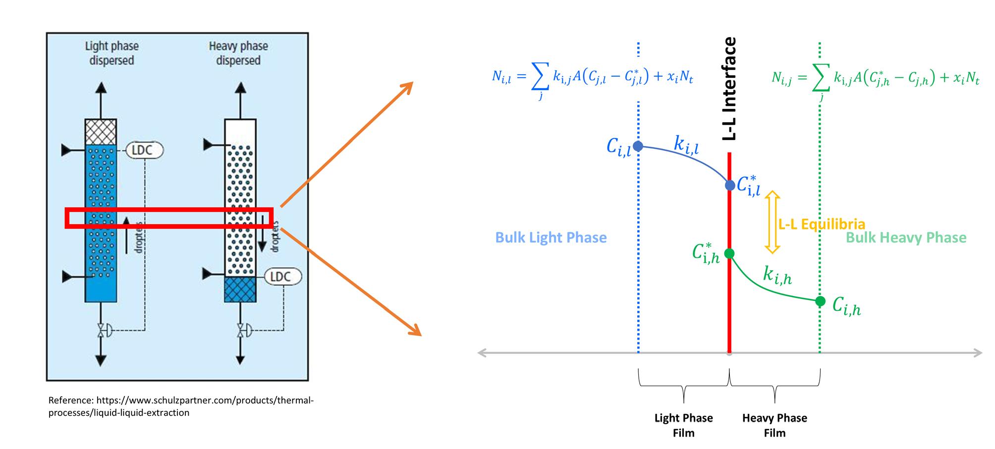
of treaters having light and heavy phases dispersed, and concentration profiles in the region of the liquid-liquid interface also showing mass transfer rate equations.
Figure 1. Schematics
efficiencies to be extremely low, and height equivalent to a theoretical plate (HETP) values to be quite high. This makes the very concept of an ideal stage in such systems completely unworkable. Acid gas removal from LPG by extraction using aqueous amines is ideally suited to the mass transfer rate-based modelling approach – indeed, it is the only approach that has any chance of working in the sense of being capable of predicting liquid-treater mass transfer performance. It is of significance here to note that reactions in the phases can enhance the rate of mass transfer in that phase. By virtue of this, for H2S, the resistance to mass transfer will be significantly larger in the organic phase than in the aqueous reactive phase.
Finally, one should mention that although properties such as density and viscosity are certainly important in setting treater performance, perhaps interfacial tension is the most important parameter of all. Interfacial tension plays a decisive role in determining how easily droplets form (interface stability), and their maximum stable size, i.e., their Sauter mean diameter. This, together with phase density difference and phase viscosities, set the drop velocity relative to the continuous phase, hence, the mass transfer characteristics of both the dispersed and continuous phases. Furthermore, surfactants affect interfacial tension, and they can be very damaging to the mass transfer rate across the droplet interface. Indeed, fine particulates in suspension tend to accumulate at interfaces and their presence can completely stop the drag-induced internal circulation driven by the relative motion of drops through the continuum. Coating the drops with small particles reduces mass transfer within the droplets to one of purely molecular diffusion, i.e., intra-droplet mass transfer almost disappears, and the treater completely stops functioning. Keeping the system clean is important.
Mass transfer rate model
The factors that affect liquid treater performance include phase equilibrium, properties of both fluids, the interfacial tension between the phases, specification of the internals, and the kinetics of the reactions taking place. Modelling approaches currently available are (i) ideal stages, (ii) rules of thumb for selecting the number of stages, whether real or ideal, and (iii) tray efficiency and HETP values, obtained largely anecdotally, and applied to the ideal stage count as established by the first two approaches cited here. The result is what the
generous would call an educated guess. Conventional wisdom puts sieve tray efficiencies for H2S removal in the 5 - 20% range and HETP values from 10 - 20 ft. To our knowledge, more sophisticated models do not exist, and there is certainly no way to account for critical internals specifications such as tray spacing, sieve hole diameter, packing type, or packing size. Complete lack of commercial models was the motivation for leveraging ProTreat’s gas treatment model as a basis for developing a liquid treater model. The starting point was rigorous, accurate electrolyte thermodynamics for amine treating; a well-established, accurate and time-tested rate model for gas treatment, carbon capture, and sulfur recovery; and a flexible flowsheeting environment within the existing ProTreat® software.
Table 1. Internals needed for equal performance to one ideal stage for H2S treating
phase controls the limitation. Interfacial area and interfacial tension are also calculated.
Case study
The example case study concerns treating 10 US gpm of LPG feed containing 3 mole% each of H2S and CO2 at 500 psig. LPG is the dispersed phase, and it is being treated with 10 US gpm of 30 wt% monoethanolamide (MEA) as the continuous phase. Table 1 shows a comparison between the performance of a single ideal stage and the number of sieve trays, the depth of biphase in a spray column, and the depth of 2 in. ceramic Raschig rings to achieve approximately the same level of H2S in the treated LPG.
Table 2. Sieve tray efficiencies and HETP values for the example case
Figure 1 shows two liquid treaters, one with the light phase dispersed (left) and the other with the dense phase dispersed (right). Also shown in the right panel are typical concentration profiles in the vicinity of the interface together with equations describing the mass transfer rates across the two mass transfer films at the interface, one in each phase.
The mass transfer rate model for liquid treatment leverages ProTreat’s® model for gas treatment which is well established. ProTreat is proven to predict actual performance data with great accuracy and shows faster convergence times. The model uses rigorous, proven electrolyte thermodynamics for treatment with amines and other solvents and is time-tested for gas treatment, carbon capture, and sulfur recovery in a completely flexible flowsheeting environment. The system of equations consists of material balances, liquid-liquid equilibria, mass flux equations, and equations for interfacial and bulk-phase energy balances. The solution to the equation set includes tray-wise or packed segment-wise phase flows, compositions, temperatures of the two phases, interface composition and temperature, and component fluxes.
Column internals that are currently implemented include stationary sieve trays (effect of hole size, percent open area, tray spacing, downcomer clearance), spray columns (mass transfer zone depth, distributor hole size, and total hole area), and a wide range of commercially available packings as well as user-defined packings.
In addition to the obvious rate model’s benefit for liquid treaters, i.e., being able to predict performance with unprecedented confidence, the rate model also offers diagnostic benefits. The calculation includes the Sauter mean diameter of the dispersed-phase droplets, as well as tray-by-tray and packed segment-by-segment interfacial compositions and fluxes. These results provide insight into the operating regime, specifically, whether the separation is limited by phase equilibrium or by mass transfer, and which
From the table, it is strikingly obvious that although a single ideal stage of contact will produce a product stream with 10 ppmv CO2 and 400 ppmv H2S, none of the real internals in quantities necessary to produce 400 ppmv H2S will give anything close to 10 ppmv of CO2 – the CO2 levels are hundreds of times greater than one ideal stage. This can be attributed to the substantially slower reaction kinetics of CO2 with amines relative to H2S. As previously discussed, the rate of reaction of a given species proportionately enhances the diffusional flux of that species. The disparity is enormous, and it is safe to say that an ideal stage model will be unreliable in estimating both H2S and CO2 performance, especially given the lack of methods available to translate ideal stages into the reality of tray counts and packed depths. Perhaps a simpler comparison of the same results would be based on tray efficiencies and HETP values as shown in Table 2. Here it can be seen that 2.5 times as many trays and 2.5 - 3 times the spray column height or packed depth would be needed to achieve the ideal stage value of 10 ppmv CO2 content in the treated LPG.
Summary
The case study is a sample of the research on the direct effect of column internals details and of switching the dispersed vs continuous phases. This is the first time it has been possible to simulate liquid treaters rationally, and to relate performance to the treater design and its physical characteristics.
Of considerable interest is the role of interfacial tension in the liquid extraction process, of which the example case is but one instance. Interfacial tension affects not only drop size, but the ability of a phase to form drops at all, and it depends on the composition of each phase, and on temperature. It plays a critical role in the extraction processes, and surfactants and contaminants, such as fine particulates, can have a profound effect on treating. The availability of a rate-based extraction model now puts extraction on the same solid footing that absorption has enjoyed for many years. Engineers can now design liquid treaters with a decent measure of confidence. But there is more to be done.
The model continues to be validated against operating plant data and further development work is being undertaken, including the implementation of agitated internals, additional mass transfer and hydraulic correlations, and applications in areas beyond propane and LPG treatment.
Varun Mathur, IPCO, provides insight into sulfur granulation technology in use at a refinery in Oman.
Evolution of the Rotoform concept has been driven by increasing capacity demands resulting from a combination of more stringent environmental legislation (meaning more sulfur is extracted) and the need to convert this into a form that is easy and safe to store, handle, and transport, often from one continent to another.
High-capacity sulfur granulators
A third factor, the rise of the ‘mega refinery’, has resulted in the need for even greater capacities. To meet this demand IPCO launched its sulfur granulator (SG) rotation drum range in 2018.
This is a fully automated, high-productivity, ‘once through’ drum granulation system capable of delivering premium quality sulfur at high throughput rates.
Three SG20 units have been installed at Duqm, with two operating around the clock to meet the daily throughput requirements and the third on standby. An easy shut down and start up process means the standby unit can take over when either of the others needs to be taken off-line for cleaning or maintenance.
While the design capacity of each SG20 granulator is 800 tpd, they have been turned down to 450 tpd per unit to meet the current daily production need of 900 tpd. These are the first three SG units to be installed in the Middle East and have been upgraded to cope with the unique local conditions.
From melt to solid sulfur
Solid sulfur seeds are generated outside the drum by freezing sprays of liquid sulfur in a water bath at controlled
pressures to form the desired size range. The particles are then conveyed into a rotating drum with appropriately placed flights attached to its inner surface. As the drum rotates, the flights create cascading curtains of sulfur particles, gradually pushing them towards the discharge end.
Mean size Between 2 and 6 mm
Size distribution Less than 5% bigger than 6.3 mm Less than 25% bigger than 5.6 mm Minimum 75% bigger than 2.88 mm
Less than 2% smaller than 1.18 mm
Less than 0.1% smaller than 0.3 mm
Moisture Less than 0.5% by weight
Friability Less than 1% fines (< 0.3 mm) under stress level I
Less than 2% fines (< 0.3 mm) under stress level II
Bulk density 1040 kg/m3 loose, 1200 kg/m3 agitated
Angle of repose Not less than 25˚
Compaction Below 0.2% fines by weight (< 0.3 mm) under static load
Below 0.5% fines by weight (< 0.3 mm) under dynamic load
Spray nozzles on a header that runs the length of the drum, coat the curtains of particles with liquid sulfur, progressively enlarging them to the required size.
The drum’s internal temperature is regulated by the evaporation of water from the nozzles positioned inside. A fan pulls air through the drum, expelling both water vapour and any airborne dust. This dust is captured by a wet scrubber before the process air is released into the atmosphere.
As a single-pass process, there is no need for screens or recycle conveyors to send sulfur through the drum multiple times. External seed generation allows wider flexibility with the incoming liquid sulfur temperature, and also provides an innovative way to recycle the sulfur waste stream from the wet scrubbing system.
SUDIC standard
The spherical shape of the granules – along with the repeated spraying and cooling of thin layers of molten sulfur as they pass through the rotary drum granulator – accommodates the natural shrinkage during the transition from melt to solid, without weakening the product.
The result is a high-quality granulated sulfur product that conforms to the SUDIC standard specifications for size, friability, bulk density, angle of repose, and compaction.
SUDIC requirements state that the formed granules must meet stringent specifications 21 days after forming. Granules formed using SG drum granulation systems meet or exceed these specifications.
Challenges associated with drum granulation
Drum granulation is not a new technology; it is a solidification process that has been used for decades. Up until now, however, it has suffered from a number of shortcomings that have adversely impacted both quality and productivity, including frequent shut downs for cleaning and maintenance, high emissions, and inconsistent operation.
In developing the SG process, IPCO’s technicians identified the root causes of each issue, and redesigned the process to alleviate – and often eliminate – the problem.
Cleaning sulfur build-up
Older drum technologies require shutdowns every 12 - 24 hours to clean out various parts of the system to maintain steady operation. Granulators can of course be run for longer but this results in an extended shutdown for more intense cleaning.
Having identified the points in the system where sulfur build-ups occur, IPCO designed the SG system to minimise this issue, enabling it to operate for a full week before the need for a short shutdown for minor cleaning.
Frozen and plugged sulfur nozzles/ product quality
Liquid sulfur needs to be maintained within a specific temperature range (approximately 120 - 160˚C), so any cold spots in the system have the potential to cause problems. Spray nozzles on traditional granulators have always been
Figure 2. View inside a drum granulator.
Figure 1. IPCO SG20 drum granulator.
Table 1. SUDIC standard specification
cold spots because they extend outside the steam-jacketing. If sulfur is not properly removed when the system is shut down, it will freeze inside the nozzle and prevent flow during the next start up. Even if the nozzle is cleared, vapour from inside the header can condense and freeze, requiring the nozzle to be cleaned or replaced before start up. A single frozen nozzle can make the difference between premium granules and an off-specification product.
IPCO has eliminated the problem with a heated sulfur spray nozzle.
Drum roller maintenance
Granulation drums are large, heavy pieces of equipment that rotate on rollers to form curtains of falling sulfur granules in the drum, and advance the granules from the inlet to the outlet. Traditionally, the drum is placed on an angle to use gravity to advance the granules, but this creates stress on the rollers and can also result in alignment issues.
IPCO granulators use angled flights to advance the product to the outlet. This allows the drum to rotate horizontally, eliminating both the risk of wear and tear on the rollers, and the need for alignment correction.
Dust emissions and scrubber waste
Drum granulators use air and water to remove heat from sulfur to allow it to solidify. Air is pulled into the drum, water is evaporated into the air as the sulfur cools, and
the air is discharged into the atmosphere. This air will contain sulfur dust that needs to be managed, and this has traditionally been achieved by one or two technologies:
n Steam-jacketed cyclone: this melts the captured sulfur dust and creates sulfur vapour. Major downsides are high dust emissions and very high consumption of steam.
n Wet scrubber with dust collection: this captures the sulfur dust and creates a waste sludge that needs to be melted, filtered, and fed back into the sulfur supply system. While producing lower dust emissions than the steam-jacketed cyclone technology, it is a more complicated process.
IPCO’s solution uses a wet scrubbing system so there is no compromise on sulfur dust emissions. The waste stream from this is recycled into the external seed generation system so the captured dust is consumed as seed in the drum.
H2S emissions
Sulfur produced from hydrocarbons contains some level of hydrogen sulfide (H2S) when it enters a sulfur forming facility. The drum granulation process involves spraying liquid sulfur through nozzles, releasing a quantity of H2S into the air stream.
IPCO’s drum technology can be equipped with an H2S scrubbing system to satisfy any environmental regulations.
Consistent operation
The production of consistently high quality granules requires conditions inside the drum to remain constant and stable. This means that one of the biggest challenges of operating a drum granulator is knowing how to adjust process parameters according to different conditions (dry/humid, day/night, summer/winter, low/high production rates). If a granulator is operated with a single set of parameters – irrespective of conditions – it cannot deliver optimum performance, leading to reduced product quality, waste water, and shutdown due to build-ups.
Knowing how a system will react under varying conditions requires a high degree of skill and experience. In the past, this could leave operators struggling to maintain consistent product quality without multiple follow up visits from the supplier.
In order to overcome this, IPCO collated and analysed a detailed database of operating records from SG systems and has created process simulations that can be applied to any operating conditions around the world.
Conclusion
Historically, drum granulation has provided a high quality sulfur product, but often at the cost of process complexity and stack emissions. This is no longer the case. The latest features incorporated into IPCO’s drum granulators resolve the biggest issues customers are facing. This ensures that all operators, regardless of experience level, have a clean process that is simple and safe to operate, while producing a premium quality solidified sulfur product.
Figure 3. Drum granulation process.
Figure 4. Solid sulfur granules.
Michael Borchwaldt, ITT Rheinhütte Pumpen GmbH, explores how sulfur pumps in refineries can aid the desulfurisation process.
In refineries, sulfur pumps are required for the desulfurisation process, sulfur charging, and sulfur granulation.
In sulfur recovery (desulfurisation) in the petrochemical industry, elemental sulfur is obtained from hydrogen sulfide (H2S). The crude oil contains the gaseous H2S, which is removed from the crude oil during desulfurisation (using catalysts and oxygen) in order to reduce the total sulfur in the end products, such as petrol, kerosene, and diesel. This reduces the environmental impact of these fuels, as the combustion of sulfur and its compounds would produce toxic gases such as sulfur dioxide. After desulfurisation, the H2S is recovered as elemental clean sulfur, which can be used for other chemical processes like manufacturing fertilizers, pesticides, medicine, cosmetics, and rubber products. The sulfur collected in pits or tanks for residual degassing is pumped onwards by a vertical centrifugal pump,
preferably with a gas tight gland packing. In comparison to mechanical seals, conventional gland packings offer high operating reliability in a vertical set up without the latent risk of shaft seal failure resulting from re-sublimating sulfur.
Historically, vertical pumps used in these applications have been single stage with separate steam jackets, shaft columns, and discharge pipes. With the heat involved in the process, and the potential for uneven temperatures in the steam jackets, this design is prone to issues caused by differing thermal expansion rates. State-of-the-art designs offer multi-stage hydraulics capable of higher heads even at low flows. The designs also feature discharge pipes and the shaft columns in one compact unit, both utilising the same steam jacket. This gives the vertical pumps high rigidity and ensures the discharge pipe and column are seeing the same temperature in the one common
steam jacket. This ensures uniform expansion and eliminates the susceptibility of the older designs.
Another field of application for sulfur pumps in refineries is their use as loading pumps to transport the removed sulfur to its destination out of the plant. In this application there is an increased risk of shaft seal failure due to the intermittent operation. For this reason, a horizontal seal-less, magnetic coupling pump is recommended, or a horizontal centrifugal pump type with hydrodynamic shaft seal (appropriate arrangements are required). Vertical centrifugal pumps are also ideally suited to this application. A few years ago, Rheinhütte Pumpen delivered a 17 m long vertical centrifugal pump, the longest ever built for liquid sulfur. The pump is part of an unloading terminal for liquid sulfur in Southern Sweden. It is installed in cylindrical storage tank and pumps sulfur at a temperature of 140˚C over several hundred metres into an intermediate tank. From there, the sulfur is delivered to the combustion furnace of a sulfuric acid plant by a horizontal magnetic pump.
Sulfur granulator application uses vertical and horizontal centrifugal pumps. After the sulfur has been extracted from the natural gas, the plant produces sulfur granules. Some steam heated chemical centrifugal pumps are used for charging the granulator with hot liquid sulfur at 140˚C.
Conveying molten sulfur is a challenge
To ensure a reliable process, all requirements and plant conditions must be discussed individually with the refiner. The most important aspect of molten sulfur pumps is the temperature of the pumped medium. The sulfur must be pumped at as constant a temperature as possible between 130 - 150˚C in order to maintain its viscous state. A steam-heated pump is therefore required. It is important here that both the temperature and the pressure of the steam are constant so that the medium also maintains a stable temperature. In principle, both horizontal and vertical pumps can be used. With horizontal pumps, attention must also be paid to the choice of shaft sealing, as this must be able to withstand the high temperatures. A hydrodynamic shaft seal is often used here. The hydrodynamic shaft seal works without contact and without wearing parts. It requires no maintenance of any sort and is particularly suitable for continuous operation. With the aid of impeller back blades and a downstream auxiliary impeller, the shaft gland is completely relieved hydrodynamically from the pump and inlet pressure. The medium is kept away from the shaft gland. During operation, the seal has no contact. As a result, there is no wear and therefore spare parts are not required. Alternatively, pumps with magnetic coupling can be used. The magnetic coupling is based on a completely different sealing principle. Here, the drive for the hydraulic part of the pump takes place through the pairing of permanent magnets whose external unit transmits the torque generated by the motor to an internal unit, which in turn transfers this to the impeller. The external or atmosphere side magnet system is separated from the internal product side magnetic system by a containment shell made of non-magnetic material. The torque needed to drive the impeller is transmitted exclusively by magnetic forces which act through the spacer can. Thus the pump is hermetically sealed.
A third solution is a special steam heated mechanical seal. Sealing is achieved through axial sliding faces which are pressed
Figure 1. Magnet coupling.
Figure 2. Hydrodynamic shaft seal.
Figure 3. Mechanical seal.
against each other by spring force, and this prevents them opening when at rest. The stationary part of the mechanical seal usually sits in a housing and the rotating unit on the shaft sleeve. In the sealing gap between the sliding faces, a lubricating film is generated by the pumped medium in order to prevent the sliding faces running dry.
In vertical pumps, the seal is not affected by the high temperatures due to the design. Seals such as stuffing box packing and lip ring seals are therefore available.
The choice of the right sealing variant depends on various factors. Firstly, how the pump is operated is relevant. For continuous operation, the hydrodynamic shaft seal is the optimum choice. A magnetic coupling is recommended for a few starts and stops, and a mechanical seal for frequent starts and stops. The solid content in the medium is another important factor when selecting the sealing variant. Magnetic couplings can be used for media with soft and non-magnetic particle traces. If the solids content is low, a mechanical seal can be considered. The hydrodynamic shaft seal is also suitable for increased solids content. Due to these factors, professional and expert advice from the pump manufacturer is required to ensure the longest possible service life of the pump.
Sulfur railcar loading facilities project
A gas plant operator in the Middle East has started a project to transport the extracted sulfur from its three gas plants by train. It is the biggest rail car loading facility in the world. The gas plants produce 100 000 tpd of sulfur. That is the equivalent of approximately 100 rail cars. In order to transport the sulfur origin to destinations up to 1400 km away the operator uses the railcars of the national railway operator. Therefore, two of the gas plants are connected to the national railway network. The sulfur of the third and smallest gas plant is pumped through a 21 km skin effect current traced (SECT) pipeline to one of the other plants. Molten sulfur storage tanks and loading shelters are located at the two plants connected to the railway. Two trains with 54 and 46 railcars respectively transport the 100 000 tpd of sulfur to the two facilities where the sulfur is further processed. For this purpose, the railcars are uncoupled from the train at the gas plants in sets of 12 rail cars and each are transported to the loading shelter by rail car movers. The loading shelter is divided into three areas, each of which has space for three rail cars. In the pre-loading zone, workers inspect the wagons for possible damage. The tanks are filled in the loading zone. Here the sulfur is pumped from the molten sulfur storage tanks into the loading arms of the loading shelter. Weigh bridge reading full amount of 100 t during the loading process. The filled wagons are then inspected again in the pre-loading zones. There are always three wagons in each of the three zones. This process continues until all 12 wagons are loaded. A rail car mover then brings the wagons back to the train and takes the next unit to the loading shelter.
For this project in the Middle East, Rheinhütte Pumpen supplied six vertical GVSO molten sulfur pumps instead of the horizontal pumps normally used in this application. The advantage of a vertical sulfur pump is the lower investment and service costs compared to horizontal sulfur pumps. Two sump pumps are used in the area of the molten sulfur storage tanks to collect the wastewater from the molten sulfur storage
tanks and the pumps. The four sump pumps for the sulfur loading hall are used in the wagon loading area to collect the sulfur from the tank drains or from leaking wagons. To minimise downtimes, the pumps were equipped with operating spare parts and a spare parts data package (SPDP).
Conclusion
Sulfur pumps are used in various processes in refineries. High demands are placed on the pumps, as they must withstand the mostly corrosive medium to ensure safe and smooth processes. The correct pump type, material, and seal are selected depending on the pumping task. Close coordination between the plant operator and the pump manufacturer is necessary to ensure all factors are considered.
Figure 4. Sump pumps inside the storage tank.
Figure 5. Molten sulfur pump on the test bench for test run.
Mark Krajewski, Aspen Aerogels, USA, provides a specifier’s guide to best practices for designing with next-generation insulation materials.
The industrial insulation marketplace is not one marked by rapid innovation. Many of the materials in use today were brought to market decades ago with the most widely used hot insulation material, mineral wool, being invented in the 1870s. Circa 1940 saw the commercialisation of calcium silicate and expanded perlite. It took another four decades before polymeric foams were introduced in the form of polyurethane (PUF), polyisocyanurate (PIR), and phenolic foams. Those materials
were mostly focused on ambient and low temperature applications. There was also the introduction of microporous silica insulation, which has excellent thermal properties but a form factor that has kept the material class from being widely adopted in industrial applications. In 2003, flexible blanket insulation based on aerogel technology was introduced. Aerogels were widely studied in the research community and possessed the best insulating properties of any known solid material.
However, the material, as originally invented in the early 20th century, was a brittle, extremely low-density monolith that did not lend itself to ease of application – and was notoriously difficult to manufacture. The dual innovations of fibre reinforcement in combination with aerogel to create a durable, easy-to-use blanket form factor, and the development of a manufacturing process to rapidly produce large amounts of material efficiently, made it possible to bring this class of materials to market.
Aerogel-based insulation
When they were first introduced to the marketplace in 2003, aerogel composite blanket insulations were met with excitement, curiosity, and some scepticism. The engineers that designed deepwater pipe-in-pipe systems were the first adopters. Other SME’s who focused on terrestrial assets took a more pragmatic view of the new technology, wanting rigorous review prior to approval. Once they greenlit its use, the benefits to the design and construction
teams became clear and the inevitable march to widespread adoption began.
Standardisation of materials
Looking at any technology adoption curve, there will always be the innovators and early adopters who see the potential in a technology and are willing to look past some of the inevitable shortcomings of that new technology coming to market. However, for technology to gain the acceptance of early majority users, it must have a far more robust ecosystem. Having a material standard which has been developed by a reputable standards society is one of the most important parts of that ecosystem. For flexible aerogel insulation blankets, that standard is the ASTM C1728-23 ‘Standard Specification for Flexible Aerogel Insulation’.
First published in 2011, the standard parses flexible aerogel blankets into types, grades, and categories (Table 1). The material types are based on the maximum use temperature of the materials in question. The grades refer to how the materials are tested for thermal conductivity, in a flat configuration via methods ASTM C177 and/or ASTM C518, or in a tubular configuration via ASTM C355. It is notable that there is a healthy debate about the applicability of using tubular thermal conductivity measurements for a material that is manufactured in a planar form factor.
Categories parse the materials further by overall thermal performance and, in the case of Grade III materials,
how they are tested for maximum use temperature rise and exothermic behaviour.
An active material standard
When the C1728 standard was first published, it contained three grades of materials. In the past three years, two more grades have been added – not surprising, considering the widespread adoption of aerogel-based insulation and the entrance of new manufacturers and materials to the marketplace. This proliferation in the standards now requires designers of insulation systems to understand how these different grades can impact design and system performance. No longer is specifying ‘flexible aerogel blanket’ sufficient to realise the performance once implicit in that specification, as historically there was only one material type each for industrial cold and hot insulation.
Thermal conductivity is the major delineating factor amongst types listed for the same application temperature range. Perhaps the most effective way to compare the materials, and garner both a quantitative and intuitive feel for the performance differential, is to design each material for the same application and diagram the resulting thickness requirements. For a hot work application this is shown in Figure 1.
The diagram details the thicknesses required of four different materials to provide matching heat loss from a 6 in. normal pipe size (NPS) medium pressure steam line operating at 700˚F (371˚C). The thickness was generated
Notes:
• Type I: subdivided into Grade 1 with Categories A and B, both tested in a flat configuration focusing on thermal conductivity.
• Type II: consists of Grade 1, Category A, tested in a flat configuration emphasising thermal conductivity.
• Type III: divided into:
o Grade 1: tested in a flat configuration with Categories A and B. Category A evaluates maximum use temperature and exothermic temperature rise at the material’s maximum use temperature, while Category B allows evaluations with the test apparatus ramping up to the maximum use temperature.
o Grade 2: tested in a pipe configuration (Test Method C335), focusing on thermal performance in pipe applications.
• Type IV: includes Grade 1, Category A, tested in a flat configuration with an emphasis on thermal conductivity.
• Type V: comprises Grade 1, Category A, tested in a flat configuration focusing on thermal conductivity. This classification assists in selecting the appropriate flexible aerogel insulation based on specific application requirements, including temperature limits and testing configurations.
Table 1. Flexible aerogel blanket grades, types, and categories per ASTM C1728
using the algorithm detailed in the ASTM C680 Standard Practice. For comparative purposes, the four material types shown are C1728 Type III Grade 1A, C1728 Type V Grade 1A, an e-glass mat treated for water resistance with a polyfluoroalkyl compound, and a traditional mineral wool.
In this scenario, the Type V material requires roughly double the thickness of a Type III material to provide the same degree of thermal protection. The Type V material performs approximately the same as a polyfluoroalkyl coated e-mat and 25% better than traditional mineral wool.
There are also noted performance differentials for material types designed for cold work. Figure 2 displays four materials designed to provide condensation control on a 12 in. NPS liquid ethylene line operating at -155˚F (-104˚C). Plainly stated, the design goal is to reduce the amount of moisture that will condense from the ambient humidity onto the insulated surface of the pipe. Excessive condensation can cause significant operational issues ranging from aesthetics, (i.e. bio growth) to safety and structural effects, as long-term and widespread wet surfaces can corrode support structures and cause slipping hazards.
In this example, the ASTM C1728 Type 1 Grade 1B material requires 70 mm of thickness to meet the design requirement. An ASTM C1728 Type IV Grade 1A material would require a 14% increase in thickness to 80 mm. Figure 2 also includes traditional materials used in cold work applications, polyisocyanurate (PIR), and cellular glass.
Implications of substituting types
The rapid development and subsequent evolution of the ASTM C1728 standard has caused confusion in the marketplace as to how and when material types can be substituted. From an engineering standpoint, the task is straightforward: select the type that is being specified, then use its corresponding thermal conductivity vs temperature curve to design the insulations thermal requirements. Where the picture gets muddled is after engineering is complete and the project is proceeding into the construction phase where different groups are now executing the work packages. In MRO work, or smaller in-plant capital projects, there may not be the engineering support readily available to assess the impacts of type substitution.
Taking the profile from Figure 1, that design can be applied to typical real-world application seen in process plants every day – delivering steam with a designed maximum temperature drop. Take that profile and apply it to a 400 m (1313 ft) pipe delivering steam to a process that, at 150 psig, needs a minimum temperature of 360˚C. 30 mm of a Type III Grade 1A flexible aerogel blanket will meet that performance. If a Type V material was substituted at the same thickness, the temperature drop would increase to 16.5˚C and not deliver the steam at the needed enthalpy. The process owner would then have to accommodate that increase, and this is typically addressed by superheating the steam to a hotter temperature if possible. The follow-on effect to this increased operating temperature is an increase in operating costs, all to overcome the initial heat loss. In this design scenario, the Type V material loses an additional 1.316 billion Btu/yr, costing the plant over US$12 000/yr just for that one section of pipe. The consequences of improper substitution of material types can be high.
Best practices
There are a variety of reasons a designer selects aerogel-based insulation. It may be related to the efficient design aspects of the material – the reduced thickness allows designers to minimise the distance between insulated assets, shrinking the footprint of the facility (Type III Grade 1A and Type 1 Grade 1B). It may be possible to take advantage of the multiple use capabilities of aerogel-based insulation blankets, such as dual thermal and acoustic protection on cold work Type 1 Grade 1B and Type IV Grade 1A. Additional benefits include the ability to pre-insulate assets and ship them fully dressed, saving time at the job site. Perhaps, most notably, aerogel-based insulation blankets are excellent at preventing corrosion under insulation (CUI), a well-known issue that plagues operators and owners. Given the different performance and capabilities of the various C1728 Types,
Figure 1. Insulation thicknesses required to achieve equivalent heat loss performance for a hot work application.
Figure 2. Insulation thicknesses required to control condensation in a cold work application.
it is critically important for design engineers to indicate which, if any, other C1728 Types would be an acceptable
alternative and explicitly provide that guidance. Incorporating this guidance as a best practice ensures construction teams charged with executing the designs have the clear direction they need to build and maintain industrial assets as originally intended.
Conclusion
The evolution of industrial insulation materials has been marked by gradual advancements rather than rapid innovation. From mineral wool in the 1870s to the introduction of aerogel-based insulation in 2003, each new material has brought unique benefits and challenges. Aerogel-based insulation, with its thermal properties and flexible blanket form factor, has seen widespread adoption in recent years, driven by its efficiency and versatility.
Standardisation, particularly through ASTM C1728, has played a crucial role in accelerating the adoption of aerogel-based insulation. This standard provides a robust framework for categorising and testing these materials, ensuring that designers and engineers can make informed decisions based on specific application requirements.
As the market for aerogel-based insulation continues to grow, it is essential for designers to understand the implications of material substitution and to follow best practices in selecting the appropriate types of aerogel flexible blankets. By doing so, they can ensure optimal performance, cost-efficiency, and long-term reliability of industrial insulation systems.
Table 2. Performance impact of improper ASTM C1728 type substitution – hot work application
Rakesh Kulkarni, Burckhardt Compression, Switzerland, examines land-based compressors and how their performance can be improved.
Across the LNG landscape, compressors play a crucial role in the efficient transport and storage of gas. Their continued reliability and efficiency are essential for effective operations in modern gas supply networks. Ageing assets can benefit from upgrades and overhauls that use the latest materials and reverse engineering techniques to update compressors and extend their service life. Even if different manufacturers supplied the original equipment, it is possible to find expertise and knowledge from a single source that can support a variety of machines and keep downtime to a minimum.
Downstream applications in LNG terminals predominantly use oil-free reciprocating compressors. These avoid the need for
lubrication systems and filter maintenance, making oil separation and gas filtration technologies unnecessary, guaranteeing the cleanliness of the heat exchangers and high-pressure re-liquefaction system.
Managing boil-off gas (BOG)
Oil-free compressors are integral to the efficient and safe operation of LNG terminals. Their primary function is to manage BOG – the vaporised LNG that results from ambient heat absorption during storage and transportation. By compressing BOG, these compressors enable its re-liquefaction or use as a fuel, minimising product loss and reducing emissions.
Figure 1. Expert on-site support is essential for fast turnarounds.
Oil-free reciprocating compressors are favoured for this role due to their ability to handle cryogenic temperatures, with inlet gas temperatures reaching as low as -170°C. They are designed with specific materials for wear components, such as piston rings and seals, to ensure reliability and to minimise maintenance under these extreme conditions.
Common designs such as the Laby® and the Laby® GI have been developed by Burckhardt Compression. These compressors are specifically designed for both land-based and marine LNG applications. They can compress gas to 300 bar without cylinder lubrication, making them suitable for both re-liquefaction processes and on-board vessels with dual-fuel engines.
Managing the local energy grid
Once BOG is reliquefied or used as a fuel, the processed natural gas can be introduced into the distribution grid. This integration ensures a continuous supply of natural gas to meet consumer demand, enhancing the flexibility and reliability of the energy supply chain. Compressors are also used for transport over longer distances and at local storage and delivery stations to maintain gas pressure.
This entire infrastructure should be properly maintained to ensure safe and reliable operation, leading to decades of dependable service. However, ageing assets will eventually need more significant interventions if they are to continue working without being replaced.
Experienced service providers can provide comprehensive revamps, including reverse engineering parts and introducing upgraded materials.
Comprehensive assessments
The event that determines the need for intervention can range from a change in local legislation, such as emissions regulations, to an unplanned outage that immediately affects productivity.
Whatever the reason, the process to identify the best solution remains the same.
The first step in revitalising a compressor is completing a comprehensive assessment to understand the condition of the equipment, the urgency of any repairs, and potential benefits of this work. Obtaining sufficient information requires a structured assessment that uses advanced measurement techniques and data analysis to identify any issues.
Using data available from the operator’s process as well as any additional sensors that may be required for a comprehensive picture, in-depth analysis should identify any bad actors. The major issues can be categorised into three main groups: reliability, excessive energy consumption, and gas emissions.
Each group has a direct effect on the business and should be addressed methodically to deliver data-driven insights and effective solutions.
Precision measurements
The monitoring and protection of reciprocating compressors is covered by the fifth edition of API 670, released in November 2014. Plants operating these machines will often categorise them as critical equipment and therefore put sensors in place to collect important data.
Over time, continuous operation causes clearances to go out of tolerance, which will induce vibrations. Sensors can be installed in several locations as part of the machine build or portable equipment can be used to establish vibration levels periodically. Whichever option is chosen, this data is some of the most important information needed to determine any potential issues.
Velocity sensors can also be used to determine vibration in the frame, crosshead, and cylinder. Their positioning is crucial in achieving accurate data that can be used to pinpoint issues. Working with the original equipment manufacturer (OEM) or a maintenance provider experienced in this application should ensure that all sensors are correctly located and calibrated.
Problems with valves, such as sticking or lost springs, can be isolated if crank angle data is available. This should be complemented with accelerometers and velocity sensors, which can be used to measure vibration, gas leak malfunctions, and overloading.
Analysing the options
Having established the areas of the compressor that require attention, the next step is defining the best course of action. There may be short and long-term solutions and the operator needs to be aware of all the available options. The OEM may not be able to deliver immediate support and replacement parts for older machines may have a long lead-time.
This is where an independent service provider with an OEM background could deliver alternative options. The ability to reverse engineer parts supported by all the required documentation is crucial to providing a fast response. Options can include upgrading the original material specifications, as well as improving clearances and sealing solutions.
With many machines having completed decades of service, materials technologies have progressed significantly since their original design was conceived. In the intervening years, there have been many significant improvements in materials and
Figure 2. A typical terminal equipped with LNG compressors.
Driving the critical energy conversation
BOOK A DELEGATE PASS
machining technologies which can now be used to extend the service life of existing assets.
Extending piston life by 300%
The BOG compressors at an LNG terminal were suffering from reduced reliability, as the first stage pistons needed to be replaced every four years. The operator approached Burckhardt Compression to investigate and resolve the problem.
The LNG storage tanks used perlite for insulation and in the older tanks it had come away from the tank walls and was being carried through the pipework to the compressors. In the cylinders, it acted like a grinding paste, predominantly damaging the first stage piston, but some perlite carried through to the second stage as well.
Increased clearances and wear to the piston ring grooves caused the sealing rings to become dislodged and trapped in the valve port, causing the rings to break. The material for the rider rings had been selected poorly and all stages were missing pressure release grooves. As a result, the original rings would need to be changed after 8000 hrs.
New materials
The engineering study determined that the best option for an improved design would be an aluminium, single-piece first stage piston, installed with new rider rings using a material optimised for dry-running, high speed, and high load applications. These would be matched with a specialist coating applied to the piston rod and a new cylinder liner, designed by Burckhardt. These improvements were projected to increase the mean time between overhaul (MTBO) from 8000 hrs to more than 24 000 hrs.
Due to the perlite being carried over to the second stage, and on occasions to the third stage, all the sealing rings were upgraded to the proprietary material from the company. Since the upgrade was completed, the first stage rings have a minimum service life of 24 000 hrs, while those in the second and third stages have been checked and reinstated, achieving over 72 000 hrs of reliable service.
Process modifications
In another example, an LNG terminal had a process that required the compressors to start and stop frequently. While they were
coming up to speed, the operation needed to flare the gas. This had both a financial cost as well as environmental implications, which required regular dialogue with the local authorities.
Predominantly, the duty compressor would run at 50% capacity while the stand-by unit remained offline. Each month, the compressors would switch operations to rotate the duty cycle and share the running interval. Each time the duty compressor came online, the operator was flaring the gas for up to an hour before the gas temperature was stable and low enough to prevent high-temperature trips.
The issue was process related rather than a specific problem with the compressors’ design. The terminal’s engineering team called in Burckhardt to investigate and recommend a solution that would improve the situation. After a detailed discussion about the existing process and the reasons for flaring the gas, it was possible to make some recommendations.
Eliminating the need to flare
The review found that the process had a desuperheater that was operating in bypass mode, so the first cooling step was not being used fully. This caused an extended cooling time, during which the gas had to be flared. By adopting a different procedure where the compressor runs in bypass mode and uses the desuperheater, there would be no need to flare the gas.
In addition, the team recommended modifying the start up sequence when both compressors were needed to meet demand. As part of the comprehensive review, further suggestions were made to improve the packing to reduce leakages. Additional recommendations on components that would improve reliability and ease of maintenance, such as valve covers with pressure bolts and improved bearing design for increased load bearing capacity, were submitted. This revised operating process could make a significant reduction to equivalent CO2 emissions, around 25 tpy, in the carbon footprint of the terminal and will also cut the financial losses of burning the gas. In addition, these changes would minimise the risk of environmental fines, at a time when local legislation was being tightened.
Conclusion
At a time when LNG operations are under increasing scrutiny from an environmental standpoint, a process review, even on a relatively new installation, can deliver improvements and cost reductions. For older installations, a review of legacy parts can reveal opportunities for improvements in terms of both materials and design.
Burckhardt Compression has developed its BC ACTIVATE assessment programme, which analyses and evaluates a reciprocating compressor from any manufacturer and delivers a series of recommendations for improvements. Extensive data collection and analysis results in a range of solutions that will improve performance, reliability, and service life.
While operators of reciprocating compressors can call on this expertise as required, the most effective solution is to engage in a long-term service agreement (LTSA) which adds value to the business, with improved lifecycle costs, operational efficiency, and accurate preventive maintenance. Together, this partnership ensures that the compressors continue to deliver dependable service, with planned outages and revamps scheduled for optimum performance.
Figure 3. Accurate data collection is crucial for identifying maintenance issues.
Brandy Johnson, Babcock & Wilcox (B&W), posits how embracing diverse hydrogen generation technologies and feedstocks can help adapt to emerging energy pressures.
Hydrogen is a versatile energy carrier that is recognised as a critical component in the transition to a low-carbon economy. It offers a means to decarbonise industries ranging from transportation to heavy manufacturing. The main energy sources for hydrogen production (natural gas and electricity) are projected to experience growing demand largely due to data centres and decarbonisation efforts. As artificial intelligence (AI) and digital infrastructure expand, they place significant pressure on already strained energy grids and natural gas systems. This competition can constrain energy availability and slow down decarbonisation efforts. An ‘all of the above’ approach to hydrogen production that embraces
a broad range of fuels, feedstocks, and novel technologies will be essential to achieving climate and energy security goals.
The energy squeeze
Global electrical demand is expected to continue to rise with the International Energy Agency (IEA) reporting a 4.3% year-over-year increase in electricity use for 2024, up from a 2.5% increase in 2023, and the agency is now predicting a 3.9% annual growth rate through 2027.1 Much of this growth is projected to come from developing nations, but the rapid growth of data centres in more-developed nations is also starting to have a significant impact on overall
electricity consumption. This amounts to an overall 15% increase in energy demand due to a combination of electrification of transport, heating, and data centres through 2027. Deloitte echoes these estimates and predicts that global electricity demand for data centres could grow to 1065 TWh by 2030,2 which is roughly equivalent to Japan’s current total annual electricity consumption. These are just a few examples that demonstrate projected increases in energy demand, but electrification and buildout of data centres are not occurring in a vacuum.
For decades, the world has been pursuing the decarbonisation of difficult-to-abate industries. Electrolysis, steam methane reforming (SMR), and autothermal reforming (ATR) with carbon capture are currently the most commonly employed methods of generating clean hydrogen. McKinsey’s 2024 Global Energy Perspective reported that by 2050, hydrogen production is projected to be two to four times greater than what it is today, with 50 - 70% of total hydrogen generation expected to come from electrolysis.3 This alone would amount to an increased demand of 4125 - 5775 TWh.
Projections for these scenarios may change significantly over time as new technologies are developed or policy changes occur. However, it is clear that rapid growth in electricity and hydrogen production could be limited by undersized and ageing energy infrastructure systems that
increase costs for both fossil fuels and renewable power. The impact of energy price fluctuations has significant implications for industry and society as a whole. In the early 2000s, US natural gas prices reached all-time highs and shut down many gas-turbine based power plants until technological breakthroughs and rapid deployment of fracking came about.4 Fuel switching and the existence of a robust fleet of power generation assets that utilised coal helped mitigate and dampen the impact of the price surge on rate payers. To circumvent these issues in the hydrogen industry, utilisation of alternative hydrogen production methods and feedstocks should be explored.
Expanding feedstock options
The use of additional feedstocks such as biomass, waste, and coal to generate hydrogen may help relieve pressure on electricity and natural gas resources. There are technologies at various readiness levels that can gasify or pyrolyse these feedstocks to create syngas, which can then be separated and purified into hydrogen and carbon dioxide (CO2) using traditional methods. For instance, biomass gasification presents a unique opportunity to create carbon-negative hydrogen, particularly when paired with carbon capture and storage (CCS). The availability of biomass as a feedstock has been assessed by multiple entities, including the US Department of Energy (DOE). The DOE’s 2023 ‘Billion-Ton Report’7 demonstrates that agricultural residues, forestry waste, and dedicated energy crops can serve as feedstock for a variety of energy technologies, offering a renewable and widely distributed energy resource. Biomass-derived hydrogen aligns well with many decarbonisation goals, particularly in regions with significant agricultural and forestry industries, such as in the Southern US, Northern Europe, and Asia. While gasification is considered to be a mature technology, it relies on capital-intensive processes and faces technical challenges associated with its performance at scale. The main challenges to cost-competitive hydrogen-from-biomass production include technology maturity, feedstock variability, tar formation, and a secure and consistent supply of feedstock, but ongoing research and demonstration projects are advancing the feasibility of biomass-to-hydrogen pathways.
Figure 1. Data centre electricity consumption from 2014 through 2028.5
Figure 2. Global price of natural gas.6
Waste-derived fuels provide another viable option for hydrogen production by leveraging municipal solid waste, industrial byproducts, tail gases, and other residue materials. While the need to recycle these materials has been identified and acknowledged, waste continues to gather in landfills in many regions, emitting methane, a potent greenhouse gas (GHG). Gasification and pyrolysis technologies can convert these waste streams into hydrogen while contributing to waste reduction and circular economy goals. Like biomass gasification, technologies that can utilise waste often struggle with technical challenges, feedstock variability, and securing consistent supply chains. Further research and development is required to make use of abundant waste materials globally.
Coal, though historically associated with high carbon emissions, remains a significant global energy resource. Gasification technologies that integrate CCS can transform coal into low-carbon hydrogen. The world has vast, underutilised coal reserves, making this a secure and reliable option, particularly in regions with existing infrastructure. These technologies exist today in various forms; however, negative public perception remains a key challenge for coal-derived hydrogen.
Alternative feedstocks can provide resilience against fluctuations in energy costs and supply chain constraints while also leveraging existing infrastructure in waste management, forest management, and mining. Advanced hydrogen production technologies must be deployed to leverage these feedstocks. This is where technologies that utilise a process called chemical looping emerge as a transformative solution that can enable feedstock diversity.
Chemical looping
Chemical looping is an advanced technology that the DOE has recognised as one of the most promising carbon capture solutions for the future.8 The process utilises oxygen carriers, typically metal oxides, that react with various gaseous and solid feedstocks while inherently isolating CO2. This eliminates the need for costly and energy-intensive post-combustion capture systems.
Babcock & Wilcox (B&W) developed its BrightLoopTM chemical looping technology through extensive laboratory, bench scale, and pilot scale testing, and has made significant investments to advance this platform, particularly in configurations that convert water into hydrogen utilising various process inputs. Unlike SMR and gasification processes, which require separate CO2 separation systems, and ATR, which also needs air separation systems, this chemical looping process integrates air separation, fuel conversion, and hydrogen generation into a single core reactor system.9 The system inherently isolates a concentrated stream of CO2, eliminating the need for a separate, costly, and energy-intensive CO2 capture system or a front-end air separation unit. This integrated approach leads to significant reductions in capital and operational costs.
The process involves the oxidation and reduction of a particle that moves through two moving bed reactors and a fluidised bed reactor, sequentially interacting with feedstock, steam, and air. The feedstock is introduced into
4. Chemical looping system for hydrogen generation.
the reducer, where it rapidly reacts with particles. The particles provide the necessary oxygen, and the reaction is assisted by carrier gases that move between the fuel and the particle, continuing to convert the fuel while reducing the particles. Due to the counter-current contact between the final feedstock conversion process and the particle, the reducer yields a stream composed of CO2 and steam with trace contaminants, and the reduced particles which then flow to the oxidiser. Concentrated CO2 flows from the reducer through treatment systems to remove minor contaminants, as required, for final CO2 use or to meet environmental regulations.
Heat is recovered from product streams to generate the required steam for the oxidiser. The steam is introduced into the reactor, where it reacts with the particles in their
Figure 3. Feedstock diversity.
Figure
reduced oxidation state. This reaction partially oxidises the particles and yields a product stream of wet hydrogen. The particles are then sent to the combustor where preheated air is introduced to fluidise and lift them while re-oxidising them to their highest oxidation state, completing the loop. The exothermic oxidation reaction provides the heat needed to sustain the process at the desired reactor temperatures. The products of the process are separate streams of H2, CO2, and O2-depleted air that have undergone required purification to meet specifications.
Facilities that are capable of producing 3 - 20 tpd of hydrogen are currently under development across the US in Ohio, Wyoming, West Virginia, and Louisiana. These facilities will utilise natural gas, coal, or biomass, showcasing the flexibility and scalability of the process. Unlike challenges posed by the intermittency of renewable energy sources, the chemical looping process relies on a controllable supply of alternative feedstocks to consistently produce low-carbon hydrogen. These systems are being designed to meet regulatory compliance and provide greater energy security while supporting the transition to a net zero emissions future.
Public perception and government policy: enabling feedstock diversity
As the hydrogen economy evolves, it will be increasingly important for the hydrogen industry to support a wide range of production pathways and advocate for equal treatment in policy. While electrolysis and natural gas reforming are central to current strategies, they may not be sufficient on their own, especially as electricity and natural gas resources come under pressure from other growing sectors, like data centres. In this context, alternative feedstocks could offer regionally appropriate and low-carbon hydrogen solutions. However, these pathways often face uneven policy support and public hesitation, particularly due to concerns about the environmental impact or their connection to legacy energy systems.
To address these challenges, consideration should be given to updating policy frameworks that focus more on carbon intensity and lifecycle emissions rather than prescribing specific technologies or hydrogen colours. A comprehensive life cycle analysis of a particular project or technology would be the most important factor when determining its value to stakeholders. The hydrogen
industry will also need to bolster its communication efforts around these approaches to help build broader understanding and trust.
Governments worldwide offer various incentives to promote the development and adoption of hydrogen generation technologies tailored to their resources and strategies. However, they often attempt to pick the winning technology rather than incentivising outcomes and allowing innovation to determine the best solution. While feedstock-diverse technology development efforts have not received the same level of support, they have garnered backing from smaller institutions focused on regional development, such as states, provinces, and non-governmental organisations. To scale up and mitigate risks associated with breakthrough technologies, continued support from federal and regional governments alongside industrial stakeholders, inclusive of alternate production pathways, remains essential.
Conclusion
Hydrogen is poised to play a central role in the global transition to a low-carbon economy, yet growing demand for electricity and natural gas, driven by sectors like data centres and widespread electrification, risks creating energy constraints that could slow progress. To navigate this challenge, the hydrogen industry can benefit from embracing feedstock diversity, especially when paired with technologies that enable efficient carbon management. Innovations like chemical looping demonstrate how alternative pathways can produce low-carbon hydrogen while reducing pressure on energy systems. By taking an ‘all of the above’ approach to feedstocks and technologies, the hydrogen industry can adapt to emerging energy pressures, support hard-to-decarbonise sectors, and secure its role as a cornerstone of the global low-carbon economy.
References
1. ‘Electricity 2025: Analysis and forecast to 2027’, IEA, (2025), https://www.iea.org/reports/electricity-2025
2. ‘As generative AI asks for more power, data centers seek more reliable, cleaner energy solutions’, Deloitte, (19 November 2024), https://www.deloitte.com/us/en/insights/industry/technology/ technology-media-and-telecom-predictions/2025/genai-powerconsumption-creates-need-for-more-sustainable-data-centers. html
3. ‘Global Energy Perspective 2024’, McKinsey & Co, (17 September 2024), https://www.mckinsey.com/industries/ energy-and-materials/our-insights/global-energy-perspective#/
4. ‘Natural Gas’, US Energy Information Administration, https:// www.eia.gov/dnav/ng/hist/rngwhhdA.htm
5. ‘2024 United States Data Center Energy Usage Report’, Berkeley Lab: Energy Analysis & Environmental Impacts Division, https://eta-publications.lbl.gov/sites/default/files/2024-12/lbnl2024-united-states-data-center-energy-usage-report.pdf
6. ‘Global price of Natural Gas, US Henry Hub Gas’, Federal Reserve Bank of St. Louis, https://fred.stlouisfed.org/ series/PNGASUSUSDM
7. ‘2023 Billion-Ton Report’, Office of Energy Efficiency & Renewable Energy, (March 2024), https://www.energy.gov/sites/ default/files/2024-03/beto-2023-billion-ton-report_2.pdf
8. FIGUEROA, J., et al, ‘Advances in CO2 capture technology - The U.S. Department of Energy’s Carbon Sequestration Program’, International Journal of Green House Gas Control, Vol. 2 (1), pp. 9 - 20.
9. TONG, A., et al, ‘250 kWth high pressure pilot demonstration of the syngas chemical looping system for high purity H2 production with CO2 capture’, Applied Energy, Vol. 230, (15 November 2018), pp. 1660 - 1672.
Figure 5. Biomass to hydrogen chemical looping plant.
Rhys Jenkins, Servomex, UK, considers how tunable diode laser technology can help overcome challenges in oxygen monitoring and measurement.
Anyone working in hydrocarbon processing will be familiar with the use of flare stacks to burn off harmful emissions. Flare stacks are among the most important safety mechanisms in industrial plants, such as those used for petrochemicals, natural gas processing, chemical production, and refineries. Burning away flammable gases released by pressure relief valves helps
to dispose of excess gases and avoids dangerous, unplanned pressure build ups. Burning the vent gas is, typically, far more environmentally responsible than releasing the gas directly into the atmosphere and is often achieved by balancing the hydrocarbons mix with air and steam to ensure a clean flame with no harmful emissions. This process can also support planned combustion over short periods during plant start ups and shutdowns.
However, somewhat less well-known is the need to monitor oxygen levels in the flare – and at the header before reaching the flare. Doing so ensures safety, maintains efficiency, and complies with European Conformity targets.
The need for accurate, continuous oxygen measurement
By monitoring oxygen (O 2 ) at the burner, it prevents a potentially explosive mixture of flammable gas and O 2 from building up. This eliminates the risk of an ignition causing a flash-back of vented gases into the plant. In vented hydrocarbons, the safe level for O 2 is between 0 - 1%, so alarms will typically alert when O 2 levels exceed 1%. Likewise, any waste gases that meet at the header on route to the flare stack must not increase O 2 above 1%. Preventing an explosive gas mixture in both scenarios by using an accurate,
fast-response measurement of O 2 at a low level is critical for maintaining plant safety.
Tools for the job
Traditionally, measuring the presence of O 2 level in hazardous situations, such as the flare stack and headers, has involved using paramagnetic technology. This is usually in the form of fitting extractive analysers with a paramagnetic cell. O 2 is strongly paramagnetic (attracted to a magnetic field) whereas other gases are only weakly affected by magnetic fields, this attraction can then be measured and used to calculate the O 2 concentration.
While paramagnetic analysers require a sampling system, they still offer a rapid response to changing O 2 levels. The problem comes, however, if the background hydrocarbons are varying considerably, which can lead to small errors on the paramagnetic analyser. For enhanced safety and more accurate measurements in these applications, a tunable diode laser (TDL) measurement is recommended either as an extractive measurement for the replacement of the paramagnetic measurement or as an in-situ measurement, offering a path average measurement with a very fast response.
Additionally, the pressure at the vent header is typically dictated by the process pressures that is connected to it, so the sample will be considered pressurised. Servomex’s TDL O 2 analysers are suitable for process pressures up to 2 bara (29 psia), while its paramagnetic process analysers are suitable for vent pressures up to 3.1 bara (45 psia). Therefore, both measurement techniques have their advantages and disadvantages.
Evolving accuracy in measurement
While traditional paramagnetic, zirconium oxide, and electrochemical instruments are effective at delivering many measurements, TDL technology offers significant advantages in response speed, reliability, and overall cost-of-ownership.
For combustion control – balancing the levels of excess oxygen and combustibles such as carbon monoxide (CO) – in fired heaters, TDL analysers offer significant benefits. Not only in efficiency and reliability, but also in safety.
Zirconium oxide sensors provide accurate, continuous O 2 measurements. Some manufacturers offer an O 2 and combustibles sensor that is integrated into the same analysis solution. However, zirconium oxide cell technologies have been challenged by the introduction of TDL technologies, delivering significant advantages.
Studies have shown the O 2 measurements for both TDL and zirconium oxide analysers to be relatively similar, and both technologies work well. Yet, the TDL measurement for CO has a faster speed of response than alternative methods, such as thick film calorimetry.
In addition, unlike other analytical solutions, TDL analysers measure across the process, providing a path average measurement that picks up changes in gas concentration quicker, not at just one point but across the length of the process. TDL analysis is very responsive,
Figure 1. Inside a paramagnetic cell.
reacting quickly to changes in concentration of the measured gas. It is also highly specific to the gas it is configured to detect, providing a highly accurate, very reliable reading.
A closer look at TDL technology
TDL technology uses a single-line, monochromatic spectroscopy technique that provides a number of measurement advantages including stable calibration, continuous fast and in-situ measurements, and the avoidance of cross-interference from other gases.
TDL analysis systems consist of a laser light source, transmitting optics, an optically accessible absorbing medium, receiving optics, and detectors.
The signal information is held within the gas absorption line shape, which is obtained by scanning the laser wavelength over the specific absorption line. This causes a reduction of the measured signal intensity, which is detected by a photodiode and then used to determine the gas concentration, and other properties.
Servomex’s TDL analyser range uses a second harmonic detection modulation technique that delivers greater accuracy, sensitivity, and reliability of measurement. This is particularly effective in low concentration measurements where gas molecule absorption lines are weak and can be close to other possibly interfering components. Choosing the right absorption line is critical.
This sensitivity returns a detection limit within 0.02% for O 2 , with a measurement update rate of five readings per second.
Advantages and applications
Increasing safety demands mean that TDL technology has become a key measurement solution in combustion applications, especially for operators using natural gas mixed with refinery gases or hydrogen as a fuel.
Unlike the point measurements offered by other techniques, TDL takes a path average, cross-stack measurement across the process. This allows the analyser to detect a flame-out situation across the entire pathlength.
Servomex provides a compact TDL analyser, the SERVOTOUGH Laser 3 Plus Combustion, which can be optimised to measure O 2 and CO plus methane (CH 4 ) at the same time. It is highly specific to these compounds so provides a detailed and reliable analysis of the process, improving safety.
In addition, the measurements it provides are taken across the full temperature range of the furnace, from start up to operation, which is increasingly being recognised as important in safety systems.
Since TDL sensing provides a light-based measurement with no sample extraction, the technology provides a very fast response to changes in the boiler condition.
This speed of response is vital, since the boiler can move from a safe to an unsafe condition within seconds, so the faster the analyser can respond, the more time the operator has to take corrective action.
GEA Ejectors for Green Hydrogen production.
The reliable tool that helps ensure green hydrogen’s purity and quality while flawlessly dealing with its explosivity.
Our liquid jet gas compressors and ejectors can also be used for:
• Production of gas phase analysis (H2) ...green hydrogen fuel cells.
• Hydrogenation processes.
• Biogas CO2 mixtures & loop-reactors.
A compact solution
Servomex offers a robust, reliable solution for the monitoring of O2 in the flare stack and vent header, in the form of the SERVOTOUGH Laser 3 Plus Process. This is a compact, tunable diode laser (TDL) analyser optimised for the measurement of oxygen in multiple gas backgrounds, providing the fastest available response to changing gas concentrations.
This analyser takes up a much smaller footprint than many similar TDL devices, making it flexible when integrating into plant processes. Its size also facilitates easy installation, configuration, and calibration. One person can set up the analyser, with the built-in display ensuring that a separate laptop is not required.
A mounting assembly for multi-direction adjustment ensures accurate alignment from the start. When combined with the quick-release mechanism, it is a simple matter to reinstall the analyser quickly and correctly after maintenance, with no requirement for realignment.
TDL technology is non-depleting, has no consumables, and requires no sample conditioning system, so maintenance costs are significantly reduced. It also features digital communications capabilities, using Modbus TCP/IP Ethernet connections.
Calibration periods are extended for many applications due to the line lock cuvette technology, which prevents drift over extended operational periods.
These analysers also incorporate ‘line lock’ technology to prevent the analyser measuring an adjacent line if the measurement gas is absent. This ensures that readings are correct and always locked on the intended measurement gas.
How line lock technology delivers reliability and safety
Line lock cuvette technology is a method of ensuring that these analysers continue to measure the targeted gas reliably.
Older TDL analysers were set to measure a given gas in the same way as newer versions; however, if none of this gas was present, the analyser would start to measure an incorrect, nearby absorption line instead. For example, a CO analyser could drift to measure an adjacent water line, returning the wrong reading.
The line lock system solves this problem. It consists of a beam splitter, a cuvette filled with the target gas, and a secondary detector. The cuvette gives the secondary detector a known target gas to sense, ensuring that it locks onto the centre of the absorption peak.
This, in turn, enables the measurement to stay ‘locked’ in position on the correct absorption line, accurately measuring the process gas even if the measurement is zero.
Traditional TDL analysis uses an inline bump cell or temporary inline reference cell, which provides a reference directly in the measurement path. However, if this interferent is continuous, it can result in a measurement error. Alternatively, if it is only used sporadically, it becomes impossible to determine if the analyser has a lock between bumps or maintenance visits.
Using the line lock cuvette containing the target gas gives the analyser a permanent, 24/7 reference which is scanned several times a second and is always available, resulting in significantly improved reading reliability.
The line lock system does not require maintenance and has in-built self-diagnostics that monitor the concentration within the cuvette. If this concentration is not detected for any reason, the analyser reports an alarm which allows corrective action to be taken.
The line lock system is ideally suited to applications where incorrect measurements may lead to heavy fines for non-compliance, or where safety is dependent on a stable, reliable measurement.
Conclusion
An accurate and reliable monitoring solution for oxygen can help plant flares reach the highest levels of safety, preventing dangerous, potentially catastrophic build-ups of mixtures containing flammable gases and O2
Paramagnetic analysers offer an effective solution to O2 monitoring in this process, but the development of TDL technology offers significant advantages in terms of speed of response and measurement stability.
Servomex’s analyser has been optimised to measure O2 across the process with a very fast response that delivers an effective, cost-efficient solution to plant operators looking to increase safety at the flare stack and vent header.
Figure 2. Close-up of the line lock system showing the cuvette and beam splitter.
Figure 3. The Laser 3 Plus installed across a stack, with line lock system (circled).
Matthew Martin, ClearSign Technologies Corp., makes a case for why nitrogen oxides are a critical pollutant and outlines a strategy for emissions abatement.
Despite an overwhelming emphasis on carbon dioxide and greenhouse gas contributing to emissions, nitrogen oxides (NOX) remain a critical pollutant. Unabated NOX emissions pose significant health and environmental risks. The role of NOX in producing smog exposes communities surrounding emissions sources to both health hazards and readily visible evidence of the impacts of industrialisation.
Selective catalytic reduction (SCR) units represent previous NOX reduction technology, achieving NOX emissions as low as 2.5 ppm. The relatively high total cost of installation, operating expense, and, more recently, the recognised
potential for secondary PM2.5 formation (a particulate so small it becomes trapped in human lungs) due to ammonia slip or by-product reactions, has delayed or stopped the universal implementation of SCRs across most industries. Fortunately, new technologies, such as the ClearSign CoreTM M1 burner, generate NOX emissions
equivalent to, or lower than, SCRs paired with conventional burners. Operators can use such technology to their economic advantage by increasing production where NOX emissions are a limiting factor, reducing total installed cost, and getting ahead of costly future changes.
The persistent challenge of NOX emissions
Combustion-related NOX is primarily produced in the high-temperature flame zone emanating from burners when providing heat for industrial processes. Once these emissions exit the stack of the combustion device, they contribute to the formation of ground-level ozone and fine particulate matter, both of which have adverse health effects. Figure 1 shows NOX emissions from and year-to-year change in NOX for the US, with data taken from the Environmental Protection Agency (EPA).¹ The data is not normalised for changing fuel sources or economic output but nonetheless shows a slow-down in reduction based on a five-year rolling average. One very possible reason for this is that all the economically feasible NOX reduction projects have been undertaken.
Regulatory landscape and financial implications
Regulatory bodies have established various compliance limits for NOX emissions throughout the world. For example, in California, US, it is common to have an emissions limit of 2.5 ppm to avoid additional fees. Non-compliance can result in substantial financial penalties. In the most extreme cases, a cessation in plant operation may be required due to the cost of implementation.
Based on the most recent and applicable data from a report prepared for the South Coast Air Quality Management district in 2020, the relative cost of NOX controls has increased significantly over time. The total installed cost (TIC) of an SCR retrofit for a fired heater has increased by a factor of 1.39, and for a boiler by 1.43 times. This was calculated by comparing costs prepared for the same units in 2014 and again in 2020.² This cost escalation is noteworthy because the Producer Price Index (PPI) over the same period for power boilers and heat exchangers increased by a factor of 1.20 while the PPI for heating equipment (non-electric) increased by a factor of 1.14.³ This implies that the total cost of installation is increasing at a faster rate than that of the capital equipment. Using Equation 1:
Where:
n PVf = the future value.
n P0 = the present cost (e.g. normalised to 1 for simplicity).
Figure 1. National NOX emissions and year-to-year percent change for the US.
Figure 2. The M1 burner firing in a heater.
Table 1. Performance data from a fielded application
n PPI = 0.065 (e.g. 0.39/6 years from the Norton data).
n t = the number of time periods (e.g. 6 [2020-2014]).
n r = the discount rate (e.g. 0.025 based on 2014 10-year Treasury Yield).
Equation 1 yields a future normalised value of 1.26 based on a current cost of 1.00 vs an invested value of 1.16 over the same period. In other words, it is a better investment to install NOX controls now rather than in the future if the total install costs continue to escalate at a similar rate. Higher discount rates will give less favourable results; however, the TIC escalation for retrofit SCRs is approaching parity with the lower end of typical hurdle rates even without any additional benefit.
The value of installing NOX controls sooner rather than later is amplified if emissions are limiting plant capacity. In this case the payback can be manifold, and the emphasis instead on how inexpensively and quickly the controls can be installed.
Technological innovations
Emerging technologies can offer a promising alternative to post combustion treatment with an SCR. The ClearSign Core M1 burner is an example of such innovation. The burner has achieved 2 ppm in a practical installation without the need for external flue gas or steam. It can be installed horizontally or vertically and uses industry standard fuel and air pressures. Table 1 shows performance data from a fielded application. For the last data point, at 80% of maximum
duty, a special NOX reducing feature of the burner was placed in service to reduce the NOX from 4 ppm to 2 ppm at the equivalent firing rate. Elements of the design of the burner can be adjusted to achieve lower NOX at lower firing rates.
The burner achieves these low emissions by precise mixing of the fuel, air, and flue gas prior to combustion. This mixture yields flame temperatures that are below that of conventional or even ultra-low NOX burners. Because the highest temperature region of the flame is where most NOX formation occurs, the reactions that would produce high NOX are inhibited. There is a balance between NOX production – which is suppressed at low combustion temperature – and CO production – which is enhanced. The M1 burner strikes this balance, exhibiting low CO emissions above 70% duty and no CO emissions above 80% duty. The temperature of the operating environment also plays a role in both NOX and CO emissions, as is the case with any burner. A higher temperature operating environment will result in much lower CO emissions and moderately higher NOX emissions.
In addition to the operating points shown in Table 1, the burner produces less NOX (even dilution corrected) at higher excess oxygen levels. At both 3.8% and 4.1%, excess oxygen data shows that the burner produced 2 ppm of NOX (dilution corrected to 3% excess oxygen), even without the special NOX reducing feature being placed in service.
The burner is shown firing in a heater in Figure 2. The burner does not use a refractory tile and so it potentially
provides a much lower load on the heater installation point when compared to other burners. It can be ramped from start up conditions to full firing rate in a few minutes, providing rapid restart for intermittent service requirements.
The M1 burner presents a cost-effective alternative to traditional SCR systems. ClearSign data from an actual installation indicates that the TIC for a burner solution is approximately six times lower than that of an SCR, although this may vary depending on specific applications. Furthermore, for industries that accept high excess air operation to reduce NOX, the M1 burner delivers lower NOX with higher efficiency, leading to fuel savings of approximately 2.75% per year from excess air reduction.
Immediate impact
For operators of fired equipment in non-attainment zones in the US there can be an immediate financial and operational impact for installation of these ‘near-zero’ NOX burners. The relative impact varies by region, industry, and local regulations, but there are some readily identifiable opportunities.
In Texas, US, emissions reduction credits are available that generally garner US$100 000/t of NOX reduced.4 For operators with a fleet of relatively high NOX burners in an industry such as midstream oil and gas production, the NOX credits may completely cover not only the capital cost, but also the TIC of the new burner. Perhaps more importantly, these NOX credits could be used to field between 2 and 10 times as many heaters at the same total NOX emissions cap.
In California, US, the burner can be readily used in once-through-steam-generators (OTSG) and certain firetube boilers. For firetube boilers, the burners can provide an alternative to implementing an SCR, relief from emissions fees, and increased fuel efficiency. The payback for installation of the burners may not meet with a near-term desirable investment return but will offset significant SCR costs and alleviate permit issues.
Conclusion
The persistent challenge to reduce NOX emissions requires technological innovation to move more equipment into cost-effective compliance. As industries seek to balance economic growth with environmental responsibility, investments in advanced combustion technologies, like the ClearSign Core M1 burner, offer a viable path forward. Using innovative burners, the industry can mitigate the health impacts of NOX, address environmental concerns, and move toward a cleaner, more sustainable future within reasonable and justifiable operational and capital costs.
4. DAMODARAN, A., ‘Cost of Capital,’ https://pages.stern.nyu. edu/~adamodar/New_Home_Page/datafile/wacc.html [accessed April 2025].
A SUPPLEMENT TO HYDROCARBON
Exploring decarbonisation technology and solutions for the downstream sector
This special supplement focuses on decarbonisation pathways for the downstream sector, highlighting innovative technology and solutions that will help you thrive within the energy transition.
Scan the QR code to download your free copy of EnviroTech 2024.
flare gas recovery or vapour recovery. Reducing an organisation’s end-to-end emissions footprint helps meet permitting requirements and provides a cleaner, safer global environment. The overall global push for cleaner energy and carbon reduction means new, tighter emissions regulations and a specific focus on reducing flare emissions in non-emergency relief scenarios. Commonly referred to as ‘zero routine flaring’, the effort requires ongoing technological advancements. Zeeco continues to engage with this initiative and has identified several ways to enhance operational control and significantly reduce flaring emissions, including monitoring technologies and transitioning to staged flare systems.
Figure 1. A fixed exit area utility tip. The tip is sized for the largest possible flow, and the required purge rate would be fixed based on the entire open area. The colours in both Figure 1 and Figure 2 correspond to the proportion of the utility tip represented in the staged array.
Figure 2. A staged MPGF where the exit area is varied based on gas flow to the flare. The variable exit area allows for optimised, reduced purge flow. The colours in both Figure 1 and Figure 2 correspond to the proportion of the utility tip represented in the staged array.
Enhanced control
To minimise emissions, the flare system must operate correctly, including having a reliable pilot system and flared gas compositions with sufficient net heating values. Enhanced control and monitoring devices, such as the ZEECO® FlareGuardianTM or ViZionTM, are often utilised for confirming, monitoring, and controlling flare operations and emissions. Additionally, technologies for identifying internal burning (burn back) or ensuring continuous pilot ignition, like the ZEECO IdentifEyeTM, are employed.
FlareGuardian evaluates the combustion efficiency of a targeted zone in real-time, while ViZion can provide bracketed destruction efficiency, NHVcz or NHVdil, for guidance on proper assist media control. Both units provide operators with live data as opposed to interpolated results from data intervals. Live data enables operators to fine-tune operational parameters to achieve proper combustion in the moment, rather than reacting to data 15 minutes or more after a less-than-ideal condition was first logged. Through regions of interest selection, IdentifEye is capable of monitoring the main flame, detecting burn back, or identifying individual pilots. Utilising selective wavelengths and IR imagery, it can monitor multiple key items in a single field of vision. Technologically advanced monitoring and control devices enable facilities to gather useful real-time data, enhance flare system control, and promote high combustion efficiency, ultimately lowering emissions.
Lower flaring emissions
Central to approaching zero routine flaring emissions is not only proper destruction efficiency through operations, but also methane mitigation via staged flaring systems. Generally, elevated flare systems require a continuous flow of non-condensable gas (purge or sweep gas) to prevent oxygen from entering the flare stack. This is vital to the safety of the flare system, personnel, and upstream equipment that might be affected by a flare mishap. Because purging is essential to safe plant operations, a continuous flow of purge gas (and its associated emissions) exists even when the flare is not in operation. Upgrading flare technology to staged or self-staging flare systems is an effective method for significantly reducing purge gas and, consequently, reducing routine emissions.
Staged flare systems
One of the biggest challenges in flare design is turndown. A flare must be sized for maximum emergency relief cases, but routine flaring means the system is operated daily at turndown or purge rates. Generally, for simple types of flare tips, the purge rate is determined by the velocity at the tip. This is true for any utility/pipe style flare tip that does not include air or steam-assist technology. The required purge velocity directly correlates with the diameter of the flare tip. The larger the diameter and open exit area at the tip, the higher the amount of purge gas needed to sustain a velocity capable of protecting upstream equipment. From a design perspective, reducing continuous fuel gas requirements is the most effective way to lower emissions when purge is needed on a flare system. Staged systems
vary the open exit area based on on-demand operational requirements and can thereby dramatically reduce continuous methane emissions from purge gas.
Instead of having one large exit area sized for a whole plant
and port sizes, making it possible to safely and efficiently combust a wide range of gases from purge flow rates through maximum relief rates.
Figure 1 shows an example of a fixed exit utility tip and Figure 2 shows how an MPGF can accommodate the whole plant relief scenario if all tips are open, or restrict the exit area based on the gas flow at the time. Reducing the always-open exit area allows for a significant reduction in purge gas while maintaining compliance with the requirement to relieve the entire facility at once in an emergency.
Variable exit sonic flare tip
For high-pressure flaring applications, Zeeco has developed a variable exit flare tip, the VariJetTM (VJ), that acts as a self-staging flare tip. The flare tip has a highly engineered discharge head that fits in a receiving cone on top of a flare tip arm (see Figure 3). This discharge head blocks flow using a proprietary tensioning device that holds the pressure back in the flare tip until the set point is reached. Therefore, gas is not released until there is enough pressure and flow to sustain a high exit velocity. Because each arm uses the tensioning device, they are self-actuated based on the amount of pressure coming in. As flow increases, pressure increases, and the arm assemblies open accordingly to ensure the overall exit area creates high velocity and a stable, upright flame. During low purge flow scenarios, all flow is directed to a central tip, and the other flare arms remain closed. As the flow to the flare increases, it builds up pressure behind the discharge heads. Once the pressure
is sufficient, all the discharge assemblies will begin to lift. The lift range is specific to the process conditions and design case for the tip. If the maximum relief scenario is not reached, the assemblies will lift in proportion to the flow/pressure the flare is receiving to maintain the optimal velocity for smokeless combustion and stable flames with no impingement on the flare tips. When the flow rate is low, the exit area is very low; therefore, a lower purge rate is needed to keep oxygen out of the flare.
All staged flare systems utilise the design principle that a reduced flare tip exit diameter converts the potential energy of the gas (pressure) into kinetic energy (velocity). Minimising or eliminating the need for a continuous purge rate by utilising staged systems or variable exit area designs will significantly reduce the overall emissions from a flare system. See Table 1 for a comparison.
Conclusion
Staged flare systems play an important role in decarbonisation by reducing the amount of purge gas needed to safely operate a flare system. While the first staged flare designs were developed more than 40 years ago, continual technological advancements have made staged flare systems a leading option for waste disposal. Staging provides a variable exit area for combusting flare streams and increasing design flexibility. New technologies are not only meeting environmental regulations but also enhancing flare performance, reducing plant utility costs, and creating a safer, cleaner environment.
A podcast series for professionals in the downstream refining, petrochemical, and gas processing industries
LISTEN NOW
Sponsored by
EPISODE 6
Leakhena Swett, President, ILTA, and Jay Cruz, Senior Director of Government Affairs and Communications, ILTA, consider the importance of trade associations and industry collaborations.
EPISODE 7
Susan Bell, Senior Vice President within Commodity Markets – Oil, Rystad Energy, discusses the impact of trade wars on global oil demand and oil prices, in light of recent US trade tariffs.
EPISODE 8
In this special episode, a panel of experts from Johnson Matthey, A.P. Moller - Maersk, Honeywell, HIF Global and the Methanol Institute provide a clear analysis of the factors influencing e-fuel pricing, the economic challenges, and strategies for cost reduction.
EPISODE 9
Brandon Stambaugh, Owens Corning Director for Technical Services, discusses engineers’ demand for education and training to support three critical phases that affect the performance and longevity of insulating systems.
Extraordinary happened when Zeeco and ExxonMobil combined forces to develop a new burner that put industry on the path to net zero. The ZEECO® FREE JET Gen 3 uses proven technology plus an innovative square burner design and staged fuel to deliver remarkable performance improvements—even with tight burner spacing —across a range of fuels. Achieve single digit NOx emissions from 100% natural gas to 100% H2 firing.