OCTOBER 2026 VOLUME 9 ISSUE 9
SMARTER IN-PIT SOLUTIONS For over 45 years, we’ve been at the forefront of innovation, providing advanced Sizer technology to industries around the globe. Whether it’s soft, sticky material or hard abrasive rock, our tailored Sizers and Sizer Stations, powered by cutting-edge technology, offer reliable and efficient solutions to simplify the complexities of modern mining operations. As a turnkey provider, we bring both the expertise and the equipment to deliver end-to-end solutions — from initial concept and design, through to manufacturing, installation and ongoing aftersales support. We’re not just a supplier; we’re your partner on a sustainable journey, committed to helping you optimize performance, reduce costs and achieve long-term success.
Discover our IPSC Solutions
WWW.MMDSIZERS.COM
CONTENTS 03 05 06
12
17
20
25
Guest Comment Industry News Asia’s Rare Earth Opportunity
29
Neha Mukherjee, Benchmark Mineral Intelligence, UK, reflects on the current landscape of Asia’s rare earth mining industry, and assesses the continent’s capacity to convert geological potential to commercial supply.
Tommi Valkonen, Sandvik Mining, Finland, investigates where successful electrification can create the greatest operational value.
33
Mine Electrification Starts With A Spark
37
Integrating Electric And Battery Electric Machines To Grid Control
Selecting The Right Comminution Equipment
Dr Caroline Woywadt, Gebr. Pfeiffer, Germany, illustrates how vertical roller mills are enhancing sustainability and boosting efficiency in mineral processing.
Improving Mine Cycle Times
Teresa Bellver-Baca, Álvaro Bendezú, Matthias Ohnesorge, and Luciano López, Sika, together with Brayan Ramos, independent consultant, discuss how a mining-tailored pumpable urea-silicate resin system can reduce mining cycle times and improve ground-support in underground mining.
Engineering Challenges Beyond The Compact Loader
Sylvain Reynier, R&D and Engineering Director, Aramine, France, describes the process of scaling battery-electric power to larger underground mining equipment.
Björn Jonsson, ABB’s Process Industries division, Sweden, underscores the importance of mining infrastructure adapting to meet the electrical, automation, and digital requirements of mines.
Ritwik Majumder, Enock Mulenga, Harshitha Konidena, Abhinav Banpela, and Harinii R, Epiroc, highlight the ways that smart machine functions can aid in system-level coordination across mixed fleets and a range of grid configurations.
41
Meeting Mining’s Dual Mandate
45
Layered By Design
49
Implementing A Unified LiDAR Platform
53
Selecting Solids Level Measurement Technology For Mining Applications
From Zero To Hero: Bringing Drones To A Mine
Eloise McMinn Mitchell, Flyability, Switzerland, examines the escalating importance of drones in mining operations – improving efficiency, safety, and access.
Battery-Electric Mining Needs A Productivity-First Mindset
Mitch Tanzer, Wabtec, Australia, outlines the safety and productivity benefits of collision avoidance systems. Christian Schorr, Hexagon’s Mining Division, Switzerland, addresses why collision avoidance works best as part of a system. Thomas Gaisecker, RIEGL, Austria, explores how a terrestrial LiDAR sensor can optimise surveying, safety, planning, and risk management for the modern digital mine.
Shivam Misra, Emerson, Sweden, explains how accurate level measurement of solids helps improve the performance and safety of mining operations, and which technologies are appropriate for each application.
OCTOBER 2026 VOLUME 9 ISSUE 9
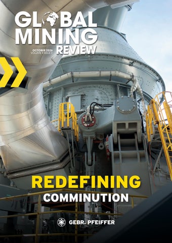
ON THE COVER Founded in 1864, Gebr. Pfeiffer is a global technology leader in crushing, grinding, and classification solutions for the cement, mining, and minerals industries. Check out Dr. Caroline Woywadt’s article (page 12) explaining how modern vertical roller mill technology can reduce energy consumption by 30 – 40%, improve mineral liberation, and enhance sustainability – offering mining operators an efficient alternative to conventional grinding circuits.
follow
@Mining_review
like
MiningReview
join
Global Mining Review
Copyright © Palladian Publications Ltd 2026. All rights reserved. No part of this publication may be reproduced, stored in a retrieval system, or transmitted in any form or by any means, electronic, mechanical, photocopying, recording or otherwise, without the prior permission of the copyright owner. All views expressed in this journal are those of the respective contributors and are not necessarily the opinions of the publisher, neither does the publisher endorse any of the claims made in the advertisements. Printed in the UK. CBP019982
Guest COMMENT AMER HAGE CHAHINE AND ILYA EPIKHIN PARTNER AND PRINCIPAL AT ARTHUR D. LITTLE MANAGING EDITOR James Little james.little@globalminingreview.com SENIOR EDITOR Callum O’Reilly callum.oreilly@globalminingreview.com EDITOR Will Owen will.owen@globalminingreview.com EDITORIAL ASSISTANT Jody Dodgson jody.dodgson@globalminingreview.com SALES DIRECTOR Rod Hardy rod.hardy@globalminingreview.com SALES MANAGER Ryan Freeman ryan.freeman@globalminingreview.com PRODUCTION MANAGER Kyla Waller kyla.waller@globalminingreview.com ADMINISTRATION MANAGER Laura White laura.white@globalminingreview.com HEAD OF EVENTS Louise Cameron louise.cameron@globalminingreview.com DIGITAL EVENTS COORDINATOR Merili Jurivete merili.jurivete@globalminingreview.com DIGITAL ADMINISTRATOR Nicole Harman-Smith nicole.harman-smith@ globalminingreview.com DIGITAL CONTENT COORDINATOR Kristian Ilasko kristian.ilasko@globalminingreview.com MARKETING & DIGITAL EXECUTIVE Sophie Birss sophie.birss@globalminingreview.com Global Mining Review (ISSN No: 2515-2777, USPS No: PENDING) is published 10 times per year by Palladian Publications Ltd., and distributed in the USA by Asendia USA, 701 Ashland Ave, Folcroft, PA. Application to Mail at Periodicals Postage Prices is pending at Philadelphia, PA, and additional mailing offices. POSTMASTER: send address changes to Global Mining Review, 701 Ashland Ave, Folcroft, PA. 19032. Annual subscription (10 issues) £50 UK including postage, £60 overseas (airmail). Claims for non-receipt must be made within four months of publication of the issue or they will not honoured without charge.
Palladian Publications Ltd, 15 South Street, Farnham, Surrey, GU9 7QU, UK t: +44 (0)1252 718999 w: www.globalminingreview.com
R
are earth elements (REEs) are critical to modern technology and the green energy transition, underpinning everything from medical devices and EV motors to consumer electronics and products in the defence and aerospace industries. With China currently controlling approximately 70% of REE mining and 80 – 90% of separation and refining capacity, other countries are now taking action to diversify supply chains and ensure they have unfettered access to the resources they need. Achieving this requires concerted action from governments, private investors, and industry stakeholders. This includes fostering national champions, supporting technological innovation, streamlining permitting processes, and encouraging international collaboration to build resilient, geographically diverse, and responsible REE value chains. We see three key pathways to success:
Diversifying primary resource extraction
The industry needs to prioritise projects in geopolitically stable regions, with a particular focus on high-value ion adsorption clay (IAC) deposits, which possess favourable heavy REE (HREE) content with potentially faster development timelines compared to traditional hard-rock mines. Despite being low-grade, their relative ease of extraction using mild chemical solutions at ambient temperatures make IACs highly valuable in the REE sector. While production is currently concentrated in southern China and Myanmar’s Kachin State, new areas are emerging as IAC hubs, particularly Brazil, Africa, Chile, and Malaysia. IAC deposits are likely to be developed sooner in regions with more permissive environmental regulations, granting these countries valuable first-mover advantages – particularly in technology piloting and the refinement of beneficiation practices. Striking the right balance in environmental standards will be a critical success factor for any country aiming to lead in this space.
Strengthening global midstream capacity
The process of turning raw REE-bearing ore into high-purity REEs is extremely complex, technologically demanding, and currently dominated by China. There is therefore a pressing need to invest in new separation and refining facilities throughout the world, which would enhance the resilience and diversity of these critical stages in the REE value chain. Companies, including Australia’s Lynas Rare Earths and the US’s MP Materials (with backing from the Australian and US governments), are notable pioneers in this effort, illustrating that a viable, global rare earth corridor that covers mining, separation, metallisation, and magnet making is no longer aspirational, but rapidly becoming a commercial reality.
Advancing the circular economy and innovation
Given that REEs are present in a wide range of products and processes, recycling them provides an alternative source of supply. However, while areas such as magnet recycling from end-of-life products and processing industrial and mining waste streams (e.g. phosphogypsum) have been identified, they are not yet effective on a large scale and require significant R&D investments to develop further. Alongside efforts to increase supply, research is focusing on reducing critical REE content in permanent magnets without sacrificing performance. While several technologies exist on this front, Grain Boundary Diffusion (GBD) deserves particular attention because, with one extra furnace step, it slashes the dysprosium/terbium content of NdFeB magnets while keeping high-temperature performance intact. Addressing the multifaceted challenges of the REE sector will require sustained investment, relentless innovation, and enhanced cooperation among governments, industry stakeholders, and research institutions. However, it is vital – securing a stable supply of these critical rare earth materials is not merely an economic consideration; it is a strategic necessity for technological advancement and a sustainable 21st century future.
WORLD NEWS Diary Dates Metals and Mining Summit 14 – 16 October 2026 London, UK & Online https://mining.live.ft.com IMARC 27 – 29 October 2026 Sydney, Australia www.imarcglobal.com Mineral Resources and Mineral Reserves Conference (MRMR) 03 – 06 November 2026 Montreal, Canada https://mrmr2026.cim.org The Mining Show 16 – 17 November 2026 Dubai, UAE www.terrapinn.com/ exhibition/mining-show FT Metals & Mining: India 17 November 2026 New Delhi, India https://live.ft.com/metalsmining-india Resourcing Tomorrow 01 – 03 December 2026 London, United Kingdom www.resourcingtomorrow.com Future Minerals Forum 12 – 14 January 2027 Riyadh, Saudi Arabia www.futuremineralsforum.com MINEXCHANGE 28 February – 03 March 2027 Denver, USA https://smeannualconference.org PDAC 07 – 10 March 2027 Toronto, Canada https://pdac.ca/convention-2027 Expomin 20 – 24 April 2027 Santiago, Chile www.expomin.cl To stay informed about upcoming industry events, visit Global Mining Review’s events page: www.globalminingreview.com/events
CHILE Metso is awarded with a thickener
modernisation order in Chile
M
etso has entered into an agreement to provide a comprehensive thickener modernisation for a customer site in Chile. The objective of the modernisation is to repower Metso’s thickeners to withstand higher throughput and operational demand, while increasing underflow density and subsequently increase water recovery. By increasing underflow density and water recovery rates, the modernisation contributes to more sustainable mining operations while supporting customers’ water stewardship and productivity objectives. The total value of the order is around €16 million, and it is the one of largest services orders Metso has received for a thickener modernisation. The full order value is recorded in the Minerals segment’s third-quarter orders received for 2026. The scope of supply includes retrofitting three Metso high-rate thickeners (belonging to the Metso Plus portfolio) by repowering them with two new Metso’s SCD 4000 drives, new mechanisms, and a redesigned high performing feed system for highly efficient thickener operation. The modernisation is designed to maximise equipment use for changing conditions while improving water recovery. “We are pleased to continue supporting our customer’s operational development in Chile. Modernising existing thickeners is an effective way to increase process performance and meet growing production demands while maximising the value of installed assets. The project will support one of Chile’s large-scale mining operations in meeting future production requirements while maximising the value of existing infrastructure”, says Benjamin Lhorente, Vice President, Sales Chile & Argentina, Market Area South America.
TÜRKIYE Deswik strengthens support for mining
customers in Türkiye
D
eswik is strengthening support for mining customers in Türkiye through an expanded in-country presence, giving customers a direct local point of contact backed by Deswik’s broader mining and software expertise With the appointment of Istanbul-based Mehmet Burak Emci as Business Development Adviser (EMEA & CIS), Deswik is making it easier for customers in the region to engage with its team, access support, and work more closely on site-specific planning and operational challenges. This expanded presence reflects a simple priority. Being closer to customers improves the quality of support. For mining teams in Türkiye, that means more direct communication, better understanding of local operating conditions, and stronger continuity between day-to-day engagement and the wider technical capability available across Deswik. “I’m excited to return to mining with a broader understanding of business operations and cybersecurity”, said Burak Emci. “Having worked in the Turkish mining industry previously, it’s especially rewarding to be back and working more closely with customers. Being on the ground allows us to better understand their operational priorities while providing a local point of contact who can connect them with the right people and capabilities across Deswik as their needs evolve.” Deswik supports mining companies with integrated software and consulting capability across mine design, planning, optimisation, scheduling, survey, and operational workflows, with the support of a global team of more than 200 mining engineers and specialists. For customers in Türkiye, the benefit is practical. Local engagement can help speed up communication, improve alignment with site requirements, and make it easier to build long-term working relationships supported by global experience. global mining review // October 2026 5
6 October 2026 // global mining review
Neha Mukherjee, Benchmark Mineral Intelligence, UK, reflects on the current landscape of Asia’s rare earth mining industry, and assesses the continent’s capacity to convert geological potential to commercial supply.
A
sia sits at the centre of the global rare earth mining industry, accounting for approximately 83% of mined production and hosting the largest concentration of operating rare earth assets worldwide. It is also at the heart of efforts to develop midstream and downstream capacity, with new projects emerging across Southeast and Central Asia. Across the whole value chain, alongside established producers. The region’s resource base is broad, spanning light and heavy rare earths, hard-rock deposits, and ion-adsorption clays. Yet geological potential does not automatically translate into new supply. Projects must overcome challenges across mining economics, mineralogy, processing, infrastructure, regulation, financing, and market access. The question, therefore, is not whether Asia has the resources. It is whether those resources can be converted into reliable, commercially scalable, and cost-competitive supply chains.
global mining review // October 2026 7
China: The advantage of integration
China currently accounts for 67% of the global mined total rare earth oxide supply. However, rare earth mining was not always dominated by China. The US was the world’s leading producer through much of the 1980s, with Mountain Pass in California supplying a significant share of global demand. China’s rise was driven by a combination of resource diversity, low-cost mining, state support, technological development, and the construction of an integrated downstream industry. Its advantage is not simply the availability of low-cost ore. It is the connection between mining, beneficiation, cracking, separation, metal and alloy production, and magnet manufacturing. China’s resource base includes both light and heavy rare earths. The Baiyun Ebo deposit in Inner Mongolia is primarily associated with light rare earths, while southern China hosts extensive ion-adsorption clay deposits that are important sources of heavy rare earths such as dysprosium (Dy) and terbium (Tb).
China’s latest inferred hard-rock resources are reported at 343 million t, including 333 million t at Baiyun Ebo and 44 million t of reserves. Ion-adsorption clay resources across seven southern provinces are estimated at approximately 12 million t. In 2025, China’s mine production was approximately 282 000 t of total rare earth oxide (TREO), equivalent to roughly 67% of global output. Industry consolidation has reinforced this position. China has consolidated a previously fragmented mining sector into two large, state-linked groups: China Rare Earth Group and China Northern Rare Earth Group. This structure gives the government considerable influence over production, investment, and supply traceability. The quota system is central to this model. Introduced in 2006, production quotas were designed to control output, formalise production, and reduce illegal mining. The system has become less transparent in recent years. In 2025, the first batch of mining and smelting quotas was issued without a public announcement, while the release of quotas later than usual earlier this year contributed to market anxiety and upward pressure on PrNd oxide prices.
Myanmar and Laos: Heavy rare earth supply
Figure 1. Asia’s share of global mined total rare earth oxide (TREO) supply in 2026 and 2031 (Unit: % of kt).
Figure 2. China’s share of global mined REE supply (Unit: % of kt).
8 October 2026 // global mining review
Myanmar has become particularly important for heavy rare earths. The country produced approximately 37 000 t TREO in 2025, making it the world’s second-largest mine producer after China. Much of this material originates in Kachin State, including areas controlled or influenced by armed groups. Myanmar is reported to account for 46% of mined dysprosium supply and 33% of mined terbium supply. Its ion-adsorption clay deposits can contain relatively high proportions of these elements, making the country a strategically important source of heavy rare earth feedstock. The same characteristics that support low-cost extraction create significant supply-chain and environmental risks. Production is largely unregulated, with limited regard for environmental standards. Disruption from conflict or monsoon conditions can affect supply and contribute to volatility in dysprosium and terbium prices. Mixed rare earth carbonate is predominantly exported to China, where it enters the country’s established separation and refining system. Myanmar’s production also illustrates the limits of mining diversification.
DEMANDING CONDITIONS
DEMAND JENNMAR
YOUR LEADING ROCK REINFORCEMENT SPECIALIST - PROVIDING HIGH CAPACITY, DYNAMIC, SINGLE PASS, AND RAPID DEVELOPMENT SOLUTIONS Our commitment to you, our customers, is guided by three words; safety, service, and innovation. We are constantly moving forward creating products of the highest quality and providing you with the services which make the impossible possible. At Jennmar fabrication takes place in our numerous strategically located manufacturing facilities associated with our affiliated brands. From bolts and beams to channels and trusses, to resin and rebar, and more, Jennmar is ideally positioned to meet the industrial fabrication demands of our customers. Discover how we can support your next project. Contact us at: info@jennmar.com. Or explore more on our website www.jennmar.com.
MASTERING THE UNEXPECTED SINCE 1960 Resins and foams for: • Ground Consolidation • Cavity Filling • Bolting with Pumpable Resins • Ventilation Control
• Firefighting • Ground Support • Waterproofing • Injections Pumps
Discover how we can support your next project. Contact us at: info.weber@jennmar.com Or explore more on our website www.weber-mining.com.
Stop by our booth!
Laos has emerged more recently as another source of heavy rare earth feedstock. Production began in 2023 and reached 17 000 t TREO in 2025, including 481 t of dysprosium, equivalent to 18% of global mined dysprosium supply. Laos’ proximity to China, and the geological similarities between its ion-adsorption clay deposits and those in southern China, add to its strategic relevance. However, production remains smaller and less transparent than in Myanmar. The country level estimates are at 0.6 million t of TREO resources and the Mengkham rare earth project
Figure 3. Historical Chinese rare earth mining half yearly quota (Unit: kt).
reported approximately 29 700 t of REO resources at the end of 2025.
India: Large resources, controlled development
India’s principal rare earth resources are associated with monazite-bearing beach and mineral sands, which contain both rare earths and thorium. Indian government data identifies approximately 13.15 million t of monazite resources containing around 7.23 million t of in-situ REO equivalent. Additional hard-rock resources have been identified in Gujarat and Rajasthan. The presence of thorium and uranium means that monazite is treated as a prescribed atomic mineral. Mining, processing, and refining are consequently subject to government control. Indian Rare Earths Limited, a state-owned company under the Department of Atomic Energy, has historically been the principal operator of the integrated mineral-sands and rare earth chain. Policy is beginning to shift. India’s National Critical Mineral Mission, launched in 2025, aims to strengthen the wider critical-mineral value chain. The government has also expanded exploration and auctioned rare earth and other critical-mineral blocks. The Aluva mine is reported to produce 2900 t TREO annually. However, India’s resources are predominantly light rare earth-bearing and associated with radioactive minerals, making extraction complex and expensive. The country also lacks sufficient midstream and downstream capacity. India therefore demonstrates the difference between resource ownership and commercial scalability. Greater mining output will require corresponding investment in separation, metals, alloys, and magnet manufacturing.
Vietnam: Significant resources, limited production
Figure 4. Mined Dy supply in Asia, split by country in 2026 and 2031 (Unit: % of kt).
Vietnam has significant undeveloped rare earth potential, led by the Dong Pao deposit and other northern deposits containing bastnaesite, monazite, and xenotime. With approximately 3.5 million t of reserves but only ~400 t of mine production in 2025, the gap between resources and commercial output remains substantial. Development is constrained by the need for domestic beneficiation, separation, and supporting infrastructure. All mineral resources are state-owned, with projects requiring government licences and approvals. Since January 2026, Vietnam has also banned raw ore exports and designated rare earths as a National Strategic Asset, requiring domestic processing to oxide or metal stage. While this supports downstream development, it raises the investment hurdle for new mines. Early moves are emerging, including a US$60 million Lynas – LS Eco Energy investment in a Vietnamese rare earth metals plant and efforts to bring international partners into Dong Pao.
Malaysia: Processing hub with mining potential Figure 5. Mined PrNd supply in Asia, split by country from 2025 to 2030 (Unit: % of kt).
10 October 2026 // global mining review
Malaysia’s importance currently comes primarily from processing rather than mining. Lynas’ Kuantan
facility has operated for more than a decade and is the largest significant light rare earth separation operation outside China. In 2025, the facility produced separated dysprosium and terbium, becoming the only commercial producer of separated heavy rare earth products outside China at that time. Malaysia is now seeking to connect this processing infrastructure with domestic resources. Ion-adsorption clay resources have been identified in Kelantan, Pahang, Perak, and Kedah. Government data estimates measured rare earth resources across nine states at approximately 274 000 t, although further work is required to establish commercial-scale resources. The potential value of these clays lies partly in their medium and heavy rare earth content. Lynas signed a memorandum of understanding with the Kelantan state investment arm in 2025 to explore future supplies of mixed rare earth carbonate to its Kuantan plant.
Mongolia and Kazakhstan: Early-stage potential
The country’s importance may therefore rest on its ability to combine geological potential with an established mining industry and state-backed financing. Commercial-scale rare earth production, however, remains at an earlier stage than in China or Myanmar.
Conclusion: Resources are only the starting point
China remains the cost benchmark, with projects estimated at around US$60/kg for PrNd and US$250/kg for Dy, but Asia’s broader resource base is highly competitive with the West. The region combines relatively low-cost deposits with significant diversity across both light and heavy rare earths, alongside proximity to major downstream markets in China, Japan, and South Korea. The opportunity is therefore less about resource availability and more about turning resources into investable, scalable supply. The winning projects will combine favourable geology, competitive costs, infrastructure, processing capacity, and reliable customers. Policy support and capital investment will be critical to making this happen. China is already the leading player in the global rare earths landscape, and with the right incentives and investment, rest of Asia has the potential to emerge as a highly competitive pillar of global rare earth supply.
Mongolia is reported to have more than 3.7 million t of REO resources, although the supplied material provides limited detail on the status of development. Kazakhstan is also at an earlier stage, but its established mining and metallurgical base make it relevant to future supply-chain development. Government geological programmes have identified areas prospective for rare earths and associated critical minerals. The Kuirektykol area, for example, has been assessed as prospective for rare earth mineralisation, while exploration has identified additional rare-metal and rare earth targets. Kazakhstan’s government is also attempting to build an investment ecosystem around critical minerals. Its Development Bank launched a US$1 billion financing programme for rare earth, rare-metal, and critical-material extraction and processing projects for 2025 – 2030, including long-tenor financing and grace periods. Figure 6. REE mining and processing hubs in Asia. Table 1. Measured and estimated REE resources in Asia. Deposit
Company
Status
Resource
Baiyun Ebo
China Northern Rare Earth Group (100%) China
Status
Operating
333 million t REO geological potential
China Rare Earth Group Hard Rock
China Rare Earth Group (100%)
China
Operating
9.6 million t REO
China Rare Earth Group Clay
China Rare Earth Group (100%)
China
Operating
12 million t
Aluva
IREL (India) (100%)
India
Operating
13.15 million t
Laos Ionic Clay
Laos Ionic Clay (100%)
Laos
Operating
~0.6 million t (Xieng Khouang + Houaphanh provinces)
Involuntary Malaysia
Involuntary (100%)
Malaysia
Operating
16.1 million t
Myanmar Ionic Clay
Myanmar Ionic Clay (100%)
Myanmar
Operating
N/A
Involuntary Thailand
Involuntary (100%)
Thailand
Operating
N/A
Vietnam HardRock
VIMICO (100%)
Vietnam
Operating
~9.7 million t REO combined across named VIMICO deposits (Dong Pao 4.7 million t + Nam Xe North 2 million t + Nam Xe South 3 million t)
Zhana Kazakhstan Deposit
Ministry of Kazakhstan
Kazakhstan Early Stage 20 million t total forecast resource
Khalzan Buregtei
Mongolian National Rare Earth (100%)
Mongolia
Early Stage 1.55 million t TREO
Khotgor
Temarise limited rare earths
Mongolia
Early Stage >2.2 million t TREO
global mining review // October 2026 11
Dr Caroline Woywadt, Gebr. Pfeiffer, Germany, illustrates how vertical roller mills are enhancing sustainability and boosting efficiency in mineral processing. 12 October 2026 // global mining review
R
ising power costs paired with declining ore grades and harder ores require a change in comminution equipment selection (Ballantyne and Powell, 2014). Reduced energy and water consumption are mandatory for enhanced sustainability. Dry grinding with a Vertical Roller Mill (VRM) offers benefits in energy savings: the energy consumption can be 30 – 40% lower than that of traditional tumbling mill systems in the mining industry. The overall benefits in terms of capital and operating expenditure must be evaluated for each project alongside the sustainability benefits, taking into account not only the grinding plant but also upstream and downstream processes.
While it may not be a one-size-fits-all solution, there is a wide range of potential applications where this technology offers obvious advantages and benefits to customers in the mining industry. VRM technology delivers substantial energy savings, improves mineral liberation and recovery at coarser grind sizes, ensures uniform size reduction with a narrow particle size distribution, and achieves remarkable reduction ratios.
Comminution principle
In the VRM the particle breakage takes place in the gap between the rollers and the rotating table. Comminution is achieved by compressive and shear stress on the particle bed; the surface
global mining review // October 2026 13
contact between the particles distributes the stress in the grinding bed. With application of sufficient stress, micro cracks are generated. In the grinding bed there are multiple contact points where pressure is applied on the particles. The mineralisation in the hard parts of the ore is liberated. The opportunity for crack initiation is higher than
Figure 1. MVR vertical roller mill.
that in a ball mill where mainly impact and shear stress is applied. The compressive comminution with an adjustable proportion (design of roller setting) of shear forces results in an energy-efficient size reduction with energy savings between 30 – 40% compared with ball mills. The size reduction ratio of a VRM is much more than 1000. A feed particle size from about 175 mm can be reduced to a particle size of P80 of 1 mm – or P99 of 20 µm or less depending on the grindability and the requirements for the product. The MVR mill is a single machine for simultaneous crushing, grinding, and classifying. If necessary, MVR even enables drying. The system can be configured according to one of several operating modes. ‘Straight grinding mode’ is selected for applications requiring a uniform grind size across all feed material to achieve grain liberation (Figure 1). The ‘De-dusting mode’ or ‘Selective grinding mode’ produces at least two different products. The mill is equipped with an additional grit extraction conveyor or chute installed below the classifier (Figure 2). The classifier coarse material (grits) is collected in the grit cone and conveyed outside of the mill system. Those grits can be used as product for downstream processes or can be classified in a single separator for different downstream purposes of use. This ‘De-dusting mode’ applies to ores where the ultrafines contain low or nil proportions of grade material or where ultrafines are interfering with the downstream process. As an example, clay material can be removed from the ore. When used in ‘Selective grinding mode’, hard material from the host rock that carries no grade is removed with grit extraction and the fines leaving the classifier are the liberated high-grade ore. Physical properties of the material are used for this mode.
Feed moisture and dust separation
Moist feed materials with a moisture content of up to 4% can be efficiently ground without the need for an external heat source. This upper limit is depending on project and material properties. Within this moisture range the MVR provides high throughput rates, reduced internal circulation, and low specific power consumption, and the integrated high-efficiency classifier ensures effective material separation. The benefits of this are reduced if the feed moisture content exceeds this range. Separation in a cyclone is more effective than separation in a bag filter for moist materials. If direct separation in a bag filter is not possible due to the high moisture content of the feed material, additional heating is required. This cost-intensive solution can be avoided by separating the material in a cyclone. Depending on site-specific environmental conditions, a hot gas generator would therefore only be required, if at all, for short periods during annual production. Only applications such as grinding for sinter feed or pellet feed may need the use of an external heat source for general operation, in this case direct separation in a bag filter is appropriate.
Air-swept process circuit
Figure 2. MVR with grit extraction.
14 October 2026 // global mining review
Vertical roller mills combine grinding, drying, and classification in a single machine. The grinding plant operates under negative pressure, i.e. a system fan is installed downstream of the cyclone or bag filter for dust collection. To obtain optimum adjustment flexibility, the system fan is equipped with a variable-speed drive
A WIRTGEN GROUP COMPANY
Tough on stone. Big on performance. MOBISCREEN MSS 1102 PRO
MSS 1102 PRO
Powerful, rugged, versatile: The MOBISCREEN MSS 1102 PRO stands out with its exceptionally robust design. It was developed mainly for use in natural stone and for high feed capacities of up to 750 t/h. The coarse screening plant excels with its easy operation – including SPECTIVE CONNECT. For greater sustainability, the MSS 1102 PRO can be operated 100% electrically thanks to its optional dual power drive. The MOBISCREEN MSS 1102 PRO – a genuine powerhouse.
www.wirtgen-group.com/mss-1102-pro-kleemann
KLEEMANN GmbH · Manfred-Wörner-Str. 160 · D-73037 Göppingen · T: +49 7161 206 0
using a frequency converter. The gas flow ensures the material transport; gas volume and gas velocities produce a relatively high-pressure loss, and therefore the system – despite significant lower overall energy requirements – has a higher mill fan power consumption compared to dry grinding ball mill systems. The pressure drop of the vertical roller mill results from the pressure drop in the hot gas duct, and the pressure drop in the nozzle ring. The difference between pressure at the classifier outlet and pressure at the mill inlet results in the total pressure drop of mill and classifier. Some equipment suppliers have the split in pressure sensors for classifier and mill, others do not. The determination of the pressure drop for the mill itself and the classifier separately gives higher potential to optimise the air swept system.
wear parts, the achievable lifetime of the different options, and how well the annual production schedule coincides with required stops. As a rule of thumb, the maintenance cycle is longer if the wear rate is low and, consequently, the resulting wear linings lifetime is several years. This is typical for limestone and quicklime grinding and does not apply for hard rock grinding. For an MVR 5000 R-4 raw mill, for example, with a capacity of 600 tph, a change of all roller and table liners may take about 30 hours. There is a wide variety of wear parts available – including Ni-hard, chromium alloy, and different ceramic solutions. They differ significantly in wear resistance and price. Latest developments by Gebr. Pfeiffer are being used in industrial MVR mills. The lifetime of those grinding parts produced in-house is longer than sinter cast.
Layout
Methodology for scale-up and exemplary case studies
The grinding plant with the MVR mill takes up a very small footprint. Layout and maintenance concepts that are ready to be implemented are available, especially for engineering companies (Figure 3). The dimensions of the MVR 6700 M-6 plant without conveying equipment are 46 m wide by 74 m long and 57 m high. Feed conveyors will be installed as opposed to bucket elevators and material is moved on closed conveyor belts. All fans are equipped with VFD’s to ensure energy-efficient operation compared to damper controlled fans. In this case, the dust collection of the ground product is done with a cyclone system consisting of two ceramic-lined cyclones with a diameter each of 10 m. The height is about 35 m. Due to dry operation the ground material can be stored in silos before further processing downstream. So, the grinding unit is decoupled from downstream processing systems and provides an additional degree of freedom in process application.
Wear and maintenance
In comminution circuits, it is possible that the secondary or tertiary crusher of a conventional grinding circuit can be replaced with the vertical roller mill due to the large feed size capacity. This reduces complexity, maintenance, and wear. The changing or hard facing of rollers and table liners are typically the most time-consuming maintenance jobs that must be done regularly on VRMs. The decision between changing or hard facing mainly depends on: the landed costs of these
Figure 3. Mining layout.
16 October 2026 // global mining review
Grinding tests for projects are conducted in the test centre with an MVR pilot plant. The process layout of this pilot plant corresponds to that of an industrial mill. In the pilot tests not only are specific power consumption and throughput at different levels of fineness determined, but also the abrasive wear of the grinding parts and the erosive wear of the mill internals. Those figures are giving the basis for scale-up and guarantees for the mill plant. Many iron ores, complex ores, and several pellet feeds have been tested and evaluated. The grinding of pebbles from a SAG mill copper ore processing plant was also part of a test programme and shows very promising results for grinding the pebbles in one step to the flotation fineness of a P80 of ~180µm. The grinding of pebbles in the MVR mill and not recirculating back to the SAG mill unburdens the circuit, opening for additional fresh feed in the SAG mill.
Conclusion
The MVR mill for dry grinding applications is a proven technology with many decades in industrial applications for grinding of hard to medium-hard materials. This flexible equipment reduces energy consumption to enhance sustainability and also improve the circuit’s overall emissions profile in ore processing. The comminution principle is improving liberation with higher recoveries at coarser grinding. Depending on the ore body, the grind size adjusted for flotation could further reduce grinding energy, produce coarser tailings, and decrease the footprint of the flotation circuit and solid-liquid separation. The grinding plant with the MVR mill utilises a smaller footprint and provides additional flexibility in the circuits. Challenges such as wear of grinding parts and mill internals are recognised and are being addressed with research and development in combination with test work. The VRM is not a one-size-fits-all solution, therefore for each project the overall benefit must be evaluated. CAPEX, OPEX, and other costs must also account for any downstream processes. The VRM is a mature technology in certain applications, but requires some adaptation in some areas for the mining industry. Based on experience in non-mining industries the challenges are known and able to be addressed.
Teresa Bellver-Baca, Álvaro Bendezú, Matthias Ohnesorge, Markus Haufe, and Luciano López, Sika, together with Brayan Ramos, independent consultant, discuss how a mining-tailored pumpable urea-silicate resin system can reduce mine cycle times and improve ground-support in underground mining.
A
s underground mines move deeper and production cycles become more compressed, anchoring is no longer only a ground-support activity. It is increasingly a productivity, safety, and cycle-time issue. Rockbolting/cablebolting remains one of the most important reinforcement methods in underground mining, particularly in sublevel stoping operations where large openings, extraction windows, and intersections expose the rock mass to relaxation, stress redistribution, and local instability. Compared with shorter rockbolts, cablebolts provide deeper anchorage and are used to reinforce larger volumes of rock. They are commonly installed in stope roofs, brows, extraction
global mining review // October 2026 17
windows, and intersections, where ground stability is critical for safe access, production drilling, blasting, mucking, and equipment movement. However, the performance of cablebolting does not depend only on the cable itself. The anchoring medium, and the time required before the system can be loaded, strongly influence the mine cycle.
The challenge of conventional grouting
Cementitious grouts are widely used for cablebolt installation and remain a proven solution in many applications. Their limitation, however, is the curing time required before the support can be fully relied upon.
In a typical sublevel stoping sequence, cablebolts must be installed and grouted before production blasting or before an area can be released for traffic and continued mining activities. In the field case considered here, conventional cement slurry required approximately 12 hours of waiting time before the supported area could be released. This delay can become a bottleneck. In stope roofs, it can affect production readiness. In extraction windows, it can delay safe access for equipment. In intersections, where cablebolting is often mandatory due to increased span and stress concentration, it can interrupt the movement of people, machines, and materials. For high-tempo underground mines, reducing this waiting period can deliver direct operational value.
Pumpable urea-silicate resin anchoring: SikaInject® 68X series
Figure 1. Schematic representation of cablebolting applications in underground mine workings. 1a – Stope roof reinforcement with 9 m cables. 1b – Extraction window reinforcement with 5 m cables.
Pumpable two-component urea-silicate resin systems, such as SikaInject 680, 684, and 687, provide an alternative anchoring approach for rockbolts and cablebolts, with very short reaction times that can be tailored according to application conditions. The resin is mixed at the point of injection and pumped into the borehole to encapsulate the bolt. The rheological behaviour of the system is designed to support overhead and inclined applications. A controlled viscosity combined with a thixotropic response helps prevent runoff or segregation during injection, contributing to reliable full encapsulation even in vertical boreholes. Unlike traditional cartridge-based resin systems, the pumpable approach enables homogeneous mixing and true full encapsulation of the bolt along the entire borehole length. This avoids potential discontinuities caused by cartridge films or incomplete mixing, which can lead to locally unbonded zones. Full encapsulation not only improves load transfer, but also provides an effective barrier against water ingress. In fractured rock masses where groundwater inflow is present, this contributes to enhanced corrosion protection of the steel bolt, supporting long-term anchorage performance and durability. Its rapid reaction allows early load transfer, helping mines reduce the time between cable installation and support activation.
Field trial in a large LATAM polymetallic mine
Figure 2. Resin injection trial in the roof of a gallery intersection. Vertical 9 m cablebolts were installed in the crown area of an intersection between underground galleries and injected with SikaInject® 684. In this trial stage, the cables were tensioned 20 minutes after resin injection, with the load limited to 5 t according to the mine’s standard procedure.
18 October 2026 // global mining review
A recent field trial was carried out at a large underground polymetallic mine in Latin America. Cablebolt applications are illustrated in Figure 1 and Figure 2. The field test objective was to evaluate SikaInject-684 resin use under real underground conditions. Figure 1 illustrates two of the cablebolting applications in underground mine workings: 9 m cables used to reinforce the stope roof (Figure 1a) and 5 m cables installed around the extraction window to improve local stability in this critical access area (Figure 1b). Testing was also performed in an intersection formed by two galleries, outside the stope extraction area (Figure 2). In this application, 9 m cables were installed vertically in the roof of the intersection to reinforce the exposed rock mass and
Table 1. Summary of field trial results for 9 m cablebolts injected with SikaInject-684 in the crown of a gallery intersection. The table shows borehole conditions, pneumatic injection parameters, injection time, resin consumption, and installation observations for 10 vertical cablebolts installed in 51 mm boreholes. The average injection time was 1 minute 47 seconds, with an average resin consumption of 21.6 l, equivalent to 27.9 kg per 9 m cable. Plates and wedges were installed 20 minutes after injection, and a 5 t tension load was applied. Test Site T (°C) Moist (%) Group Code
A 29 – 30 84 – 85% B
1 2 3 4 5 6 7 8 9 10
Length (m)
9
Average
Borehole Resin Injection Pneumatic pressure Injection Drill-bit % borehole Injection Injection time Injection resin for injection resin diameter (mm) filling hour (min:sec) weight (kg) pump (bar) volume (lt) 16:05 01:45 20 25.7 16:08 01:42 20.9 26.9 16:12 01:39 20.8 27.2 16:15 01:45 20 25.7 16:24 01:36 22.7 29.2 51 6 100 16:58 01:55 21.8 28.1 17:03 01:44 21.8 28.1 17:11 01:59 23.8 30.6 17:15 01:53 23.6 30.4 17:19 01:48 20.6 26.5 01:47 21.6 27.9
improve local stability. These areas are critical because the excavation geometry increases the exposed span and can promote stress concentration, local relaxation, and potential block instability. The trial used boreholes drilled with a 51 mm diameter drill bit, 0.6 in. diameter seven-strand cablebolts with an ultimate tensile strength of 26 t, and a pneumatic pump for resin injection into the boreholes. The average time required to fill a 9 m borehole was approximately 1 minute 45 seconds, with an average resin consumption of 2.4 l/m, equivalent to 3.1 kg/m. Plates and wedges were installed, and the cables were tensioned according to mine standard of 5 t approximately 20 minutes after injection (Table 1). Additionally, pull-out tests were conducted by mine personnel in the sidewalls, as maximum-load verification tests are not carried out in gallery intersection roof for safety reasons. The acceptance criterion for the anchorage system was 20 t. Cables filled to 100% exceeded this requirement after approximately 25 minutes, while cables filled to 80% exceeded the same requirement after approximately 40 minutes. Cables filled to 50% reached 82% of the required load after 25 minutes and more than 90% after one hour, although further testing was recommended due to operational limitations during the trial. Partial encapsulation was assessed only as part of the field evaluation; for production applications, full borehole encapsulation remains the recommended practice to ensure consistent load transfer and reliable ground-support performance.
Operational impact
The main conclusion from the trial was not simply that the resin achieved anchorage strength. It was that the support system could be activated much faster than with conventional cement slurry. Reducing the waiting period from around 12 hours to less than one hour creates a clear opportunity to improve mine cycle efficiency. In intersections, it can accelerate the release of critical access points. In stope preparation, it can support faster readiness before production activities. In extraction windows, it can reduce the time equipment operates near unsupported or partially supported ground.
This has both safety and productivity implications. Faster load transfer reduces the exposure window between installation and effective support, while faster release of headings can reduce delays in the production sequence.
Towards verified ground support
The wider industry trend is moving from installed support to verified support. Mines increasingly require systems that are not only strong, but also fast, consistent, and compatible with mechanised installation and quality control. Pumpable resin anchoring fits this direction. It allows better control of injection, borehole filling, curing time, and pull-test verification. When integrated with mechanised bolting equipment and (ideally) digital QA/QC, it can become part of a more reliable ground-support workflow. For mining companies, the decision is therefore not only a comparison between resin and cement on material cost. The more relevant measure is the total value delivered through reduced waiting time, improved support readiness, less rework, better installation control, and safer access to critical areas.
Conclusion
Cablebolting/bolting is essential in modern underground mining, especially in sublevel stoping operations where large spans, intersections, and extraction windows require deep reinforcement. As mines push for faster and safer cycles, the anchoring system becomes a strategic part of ground support. The SikaInject 68X series, a mining-tailored pumpable urea-silicate resin system, offers a practical route to early load transfer, controlled encapsulation, and faster release of supported areas. The field trial at a large LATAM polymetallic mine demonstrates that resin-based cablebolt anchoring can deliver rapid installation, early pull-out performance, and a significant reduction in waiting time compared with conventional cementitious grouting. For underground mines seeking to improve both safety and productivity, this represents a clear step from simple anchoring towards assured ground support.
global mining review // October 2026 19
20 october 2026 // global mining review
Eloise McMinn Mitchell, Flyability, Switzerland, examines the escalating importance of drones in mining operations – improving efficiency, safety, and access. Figure 1. The Ernest Henry Mine has been excavating underground since 2011.
I
n 2023, Evolution Mining’s Ernest Henry Operations in Australia had zero drones involved in inspecting, surveying, and mapping its site. Now they have a fleet of eight and a dedicated drone pilot team. How could a mine go from zero to eight so quickly, and what are the successes driving that adoption? One of the largest copper reserves in the world, Evolution Mining’s Ernest Henry Operations is a paragon of efficiency. Breaking ground in 1998, the site’s copper-gold-silver operations focused on open-cut mining. In 2011, this transitioned to an underground operation that burrowed beneath the 2 km wide pit. The mine uses sub-level caving, which is a technique widely recognised for efficiency and lower cost ‘mass mining’. Every year, more than 6 million t of material is moved and processed – and operations are expected to continue until at least 2040. As this well-established mine transitioned from opencast to underground mining, the workforce evolved to adopt new techniques and technologies to support their operations and prioritise safety above all. In 2023, a new surveyor joined the team and asked a question: “Although we are working underground, are there drones we can use for mapping and surveying complex environments?” The idea was not rejected – it was studied.
What do drones offer mining today?
Drones have evolved past being holiday photography tools – they are delivering life-saving medicine and supplies in many countries, inspecting unsafe areas, and assessing the hulls and tanks of cargo ships. Ernest Henry’s senior surveyor had seen drones deployed at other mines and introduced the idea of bringing them to this site. Drones specific to mining, such as the Elios 3, are already deployed at mines around the world, proving their value on a global stage. Their uses range from ad hoc emergency response – such as locating orepass hang-ups – to standard surveys, where the drones can save time and provide quick, remote access after a blast or as part of preliminary surveying. The list of the benefits of drone inspections is attractive to many mines too. The remote gathering of survey data limits human risk exposure, improving safety standards while ensuring quality data collection. It is fast, detailed, and accurate down to the centimetre – a level that suffices for many mining operations. Drones like the Elios 3 are designed to do this work. This UAS is robust, capable of gathering LiDAR and visual data, with additional payloads available such as ultrasonic thickness gauges for non-destructive testing on crushers, mills, and silos. The evolution of drones from visual tools to full inspection packages has brought them to the forefront of mining technology – a big impact from a drone that measures less than 60 x 60 cm in size.
Step-by-step: Adopting drones at Ernest Henry
After the initial research by surveyors at Ernest Henry, they decided on the Swiss-designed Elios 3. They wanted to test the drone on-site and determine if it could match their needs. The key aim was to use it to inspect the ore passes in the mine. These passes are challenging to inspect. In the past, the team lowered scanners down on ropes or cables, sometimes using small cranes to help. However, these methods had limited success and often provided little valuable information. Covers over the shaft entrance, called grizzlies, meant that large equipment could not be lowered down, further limiting the team’s access and insight into the condition of the ore passes. However, when these passes need new shotcrete or have a blockage, it is vital to be able to understand the situation at hand, making inaccessibility an obstacle to resuming standard operations. The surveyors brought the Elios 3 on-site and put it to the test. The drone boasts a 4K camera, 16 000 lumens of light, and a LiDAR payload – an impressive-sounding array of equipment. They wanted to prove it worked.
global mining review // october 2026 21
They flew the Elios 3 down a 55 m long shaft. The drone’s external cage protected it when it bumped into the pass sides as it flew down, while the surveyors studied the pilot’s perspective on the remote controller. The screen transmitted the video feed as well as a live LiDAR point cloud, showing the exact position of the drone within the raise. The test proved the drone could not only easily access the space, but could also successfully fly up and down without the team having to stand near the raise at either end. This is vital as the team used to have to stand near the bottom of the pass to gather data – now they could remain a safe distance away while the drone collected critical data. Figure 2. Underground tunnels, chutes, and stopes can all be surveyed with specialised underground drones – even in cases with heavy dust and minimal lighting.
Figure 3. The Elios 3 measures just 50 x 50 cm and can be deployed in narrow, confined spaces for visual inspections alongside LiDAR scans.
Figure 4. The Elios 3 offers the pilot total visibility while they remotely collect data – a safety innovation that the Ernest Henry team were excited to deploy as part of a wider drone programme.
Figure 5. Drones offer mines a host of applications, ranging from stockpile measurements to surveying ore passes to inspecting equipment. Ernest Henry’s drone programme is an example of the success a drone programme can achieve by improving safety, reducing downtime, and simplifying data collection.
22 october 2026 // global mining review
Opening the door to drones
Not long after this test, the Elios 3 and other drones were brought to the site for various indoor and outdoor applications. The surveying team soon found that the uses of drones were not limited to surveying raises. Every week, a scan of the concentrate ore shed must be taken. In the past, 15 – 20 scans would be taken of the area with a terrestrial laser scanner, taking 4 – 5 hours of work. Merging the scans could propagate errors in the point clouds, leading to frustration with the reliability of the results. Now, the Ernest Henry team uses the drone to complete a single, 10 minute flight of the same area. It takes a few minutes but eliminates the error propagation from merging point clouds and results in minimal disruption to operations in and around the ore shed. A drastic reduction from 5 hours of scanning to less than 30 minutes, during which time the shed is inaccessible to trucks and other machinery. In addition to the successful deployment of the drone to inspect ore passes, it was used to survey ventilation shafts. Here, the drone flies inside the rise that is drilled by the raise bore drill to measure its size and dimensions. This information is shared with the ventilation engineer, who can then model ventilation flow based on the accurate models from the drone. Although designed to tolerate confined spaces, the Elios 3 has also been deployed in more open spaces, including scanning drives for over and underbreak. It can provide the relevant data for volume calculations and measurements, streamlining work across departments.
A modern drone inspection programme underground
Today, Ernest Henry has seven trained drone pilots and five different models of drones alongside their traditional scanning tools. The exploration and eventual integration of drones in the mine’s workflows highlights Evolution Mining’s future-focused methodology, which encourages mines to explore and adopt new technology in a way that optimises operations and prioritises the safety and efficiency of the workforce. This open attitude at Ernest Henry has led to multiple departments benefiting from the use of drones, unlocking smoother workflows across the site. Drones are here to stay, in part because their advantages related to efficiency, safety, and access are undeniable. Underground operations have been transformed by them around the world – Ernest Henry is yet another example of the success wrought by turning to innovation in the digital era. Smart mines are not a pipe dream – they are already here.
A new podcast for mining professionals:
driving the conversation on the tech, trends, and minds behind the mines
Figure 1. Energy modules for ARAMAC’s L140B and L440B battery-electric loaders.
Sylvain Reynier, R&D and Engineering Director, Aramine, France, describes the process of scaling battery-electric power to larger underground mining equipment.
B
attery-electric technology has moved from being a promising alternative to becoming a proven production tool in underground mining, particularly for compact loaders operating in narrow-vein and low-profile headings. Machines with payload capacities ranging from 1 – 5 t have accumulated several years of operational data, validating battery-electric powertrains under real mining conditions. As the industry now seeks to extend
electrification to medium and larger-sized equipment categories intended for headings whose dimensions extend well beyond the narrow-vein segment, new engineering questions are emerging. Scaling a battery-electric architecture does not simply mean installing larger battery packs: it involves rethinking thermal management, safety systems, machine architecture, and the economics of charging at fleet scale.
global mining review // October 2026 25
Why larger equipment is entering the electrification debate
For most of the past decade, a significant share of electrification efforts in underground mining has focused on compact equipment operating in constrained headings where ventilation limitations made diesel engines particularly costly to operate. These environments provided an early and clear use case for battery technology. At the same time, several major mining equipment manufacturers have developed battery-electric machines with much higher capacities, with trucks now reaching payloads of up to 50 t. Electrification is therefore progressing simultaneously across the full spectrum of equipment categories, with each size segment presenting its own technical and operational challenges to address. As mines with larger headings, typically around 4 x 4 m and above, face increasing pressure to reduce ventilation costs and improve air quality, equipment manufacturers are being asked to reproduce these benefits on a larger scale. Larger headings generally support production cycles involving greater volumes of ore, larger blasts, and therefore higher-capacity loaders and trucks. Electrification of this category of equipment could lead to a proportionally greater reduction in ventilation requirements and thermal load, as larger diesel machines are generally the main source of heat underground. However, the technical path to achieving this is significantly more complex than simply replicating the powertrain architecture used on smaller machines.
Density, mass, and thermal management at increased capacity
The most immediate engineering challenge in scaling up battery-electric equipment lies in energy density and the associated thermal behaviour of higher-capacity battery packs. As payload capacity increases, the energy required to support production cycles also increases, which in turn increases the physical size and mass of the onboard battery pack. Unlike diesel fuel, whose energy density remains
constant regardless of tank size, battery packs experience diminishing returns as their capacity increases: larger packs generate proportionally more heat, both during discharge and charging, and this heat must be actively managed to preserve cell life and maintain safe operating temperatures. Cell format has proven to be one of the most effective levers available to manufacturers for improving energy density without simply increasing the physical footprint of a pack. In recent years, several equipment manufacturers have transitioned from cylindrical lithium iron phosphate (LFP) cells to prismatic LFP cells, a change that has made it possible to nearly double energy density for an equivalent pack volume. ARAMAC, a French manufacturer of underground mining equipment, made this transition approximately 4 – 5 years ago across its range of battery-electric loaders, illustrating how innovation in cell format can significantly ease the space constraints associated with increasing battery capacity without requiring a change in the underlying cell chemistry. Effective thermal management becomes increasingly critical as pack size increases. Liquid cooling systems, rather than passive or air-cooled designs, are generally required for higher-capacity packs, adding complexity, weight, and maintenance constraints to the overall machine design. Engineers must balance this additional mass and volume against the machine’s payload and manoeuvrability requirements, particularly within the physical constraints imposed by an underground heading. Fast charging, often desirable for minimising downtime in continuous production cycles, further increases the thermal challenge, with fast charging generating significantly more heat than standard charging. Battery management systems designed for high-capacity packs must therefore incorporate more sophisticated monitoring and control logic to prevent degradation or hazardous conditions. Cells subjected to frequent fast-charging cycles under inadequate thermal control tend to degrade more rapidly, which can erode the total cost of ownership advantage that battery-electric equipment is intended to deliver over time.
Safety challenges for higher-capacity battery packs
Figure 2. ARAMAC L440B battery-electric loader operating underground, with a close-up of its energy module, equipped with the company’s Quick Replacement System.
26 October 2026 // global mining review
Battery safety is a central consideration in any electrification programme, but the challenges increase with pack capacity. Thermal runaway, a chain reaction in which one cell overheats and triggers overheating in adjacent cells, becomes a more significant risk in larger packs simply because more stored energy is involved in the event of an incident. Battery management systems for larger machines must therefore incorporate more detailed, cell-by-cell monitoring capable of detecting early indicators of cell stress, such as abnormal voltage readings or unusual temperature gradients, well before a fault becomes critical. Cell chemistry selection is increasingly being presented as a safety decision rather than one based purely on performance, particularly in the underground environment. Unlike a battery-electric
vehicle operating on the surface, where occupants can evacuate relatively easily in the event of an incident, underground equipment operates in confined headings where evacuation is inherently more constrained. This reality has led several manufacturers, including ARAMAC, to favour LFP chemistry over alternatives offering higher energy density but greater thermal instability, prioritising a lower propensity for thermal runaway over marginal gains in energy density. As equipment categories scale up and onboard energy capacity increases accordingly, this safety-first approach to cell chemistry selection is expected to remain a determining factor across the industry, even as manufacturers explore other avenues, such as cell format, to improve density within the same chemistry. Physical containment strategies also evolve with scale. Larger battery enclosures require robust structural protection against impacts, given the exposure of the underground environment to rock falls, collisions, and vibration. The design of venting and fire suppression systems, intended to safely direct any thermal event away from the operator cabin, becomes a more demanding engineering exercise as the volume of onboard energy increases. Compliance with recognised safety standards for lithium-based systems remains a baseline requirement, but manufacturers scaling up to heavier equipment categories are increasingly required to demonstrate safety performance specific to their larger pack configurations, rather than relying solely on data from smaller systems that have already been validated.
Machine architecture and charging economics
Scaling up a battery-electric powertrain also affects the overall architecture of the machine. A heavier battery pack changes the centre of gravity and load distribution across the axles, which in turn affects stability, tyre wear, and manoeuvrability on the ramps typical of underground haulage routes, requiring engineers to rethink the chassis, suspension, and axle configuration accordingly. This is particularly relevant for trucks, where the payload-to-mass ratio is closely scrutinised: a truck carrying a heavier onboard energy system must still achieve its productivity targets in terms of tonnes moved per shift. Manufacturers are increasingly turning to modular energy systems sized according to specific duty cycles, allowing operators to adjust battery configuration to haul distance, ramp gradients, and production schedules. Compatibility between loaders and trucks sharing common energy module concepts also enables mines to plan charging infrastructure and spare battery inventories at fleet level rather than on a machine-by-machine basis. This charging dimension becomes more pressing as equipment categories scale up: a single larger machine may require significantly higher charging power, within an acceptable operational window, than several smaller units combined, raising questions around grid capacity and the number of available charging points. Battery-swapping approaches are gaining traction in response to this challenge. ARAMAC applies this principle across its range of battery-electric loaders through what it calls a
28 October 2026 // global mining review
Quick Replacement System, allowing a depleted energy module to be exchanged for a charged module within a few minutes. As the company expands its offering towards higher-capacity loaders and trucks, in the 7 t category and above, it has indicated that this modular swapping principle will continue to underpin its approach, based on the observation that decoupling charging time from machine availability becomes increasingly valuable as onboard energy capacity increases. This illustrates a broader industry trend: as battery packs scale up, the operational cost of tying downtime to charging duration becomes more significant, making modular and interchangeable energy architectures increasingly attractive for larger equipment categories, provided mines can accommodate the additional handling and storage logistics they entail. Cost trends in cell manufacturing are also shaping the economics of scaling electrification. LFP cell prices, which have declined significantly as a result of the expansion of global manufacturing capacity, are gradually reducing the cost gap between diesel and battery-electric equipment across equipment categories. Several industry analyses anticipate price parity in the coming years for certain equipment categories, an evolution that would remove one of the last significant barriers to wider adoption of electrification in medium and large-sized underground equipment.
Electrification as a catalyst for automation
An additional dimension, increasingly discussed within the industry, concerns the relationship between electrification and automation. Electric powertrains offer inherently finer control of torque and speed than diesel-hydraulic systems, characteristics that are well suited to the precision required for remotely controlled or autonomous operation. As underground mines seek to increase automation to improve safety and production consistency, the convergence between battery-electric propulsion and automated control systems is expected to accelerate, with larger equipment categories benefiting from lessons already learned through the autonomous deployment of smaller battery-electric units.
Outlook
Extending battery-electric technology to medium and larger-sized underground equipment categories represents a logical, although technically demanding, progression for the mining sector. Success will depend on manufacturers’ ability to manage the thermal and safety implications of larger battery packs, adapt machine architecture to accommodate increased onboard mass without compromising productivity, and align charging strategies with the realities of electrical infrastructure at fleet scale. As cell costs continue to decline and thermal and safety engineering advances, the economic and operational case for electrifying larger underground equipment is expected to strengthen significantly over the coming years, extending the emissions, ventilation, and working-condition benefits already demonstrated by compact equipment to a broader share of underground mining fleets.
Figure 2. Toro LH518iB loader in operation while undergoing a series of tests in the Sandvik Test Mine in Tampere.
Tommi Valkonen, Sandvik Mining, Finland, investigates where successful electrification can create the greatest operational value.
F
or the past five years or so, battery-electric mining has been discussed primarily in terms of sustainability. Reducing diesel emissions underground, improving air quality, and lowering ventilation requirements gave mining companies compelling reasons to begin exploring electrification, particularly as environmental targets climbed the corporate agenda.
Those benefits remain real, but experience has shown that they are rarely what determines investment beyond trials. Experience with early battery-electric fleets has provided the mining industry with something far more valuable than proof that the technology works. It has generated years of operational experience across a wide range of
global mining review // October 2026 29
underground operations, revealing not only where battery-electric equipment performs exceptionally well, but also where it falls short of expectations. That distinction matters because no two underground mines are the same. Mine layout, haul profiles, ventilation constraints, power infrastructure, and production targets all influence whether electrification will deliver a meaningful operational return. As those deployments have matured, it has become increasingly clear that battery-electric equipment is not a universal solution. Like any mining technology, it creates the greatest value when it is matched to the right application. This represents an important step forward for the industry. Production fleets have already demonstrated that battery-electric equipment can outperform diesel models. The more pertinent question is where electrification creates enough operational value to justify the investment.
Productivity changes the business case
That question ultimately comes back to why mining companies invest in load and haul equipment in the first place. A loader or truck is a production asset. Its purpose is to move more material, safely, reliably, and at the lowest possible cost per tonne. Those expectations have not changed simply because the power source has. Battery-electric equipment must be judged by those same value drivers.
This is where the industry’s thinking has evolved. There is no question that eliminating diesel engines improves the underground environment. Reduced emissions, lower heat generation, and decreased ventilation demand remain important advantages, particularly as mines become deeper and energy costs continue to rise. However, experience from early deployments has shown that these benefits alone are rarely enough to support investment in production equipment. The strongest business cases are increasingly being built around operational performance. Production data from underground mines now shows that battery-electric loaders and trucks can outperform equivalent diesel machines when deployed in the right conditions. Sandvik cases have shown that across multiple operations, productivity improvements of between 20 and 34% have been achieved under normal production conditions, based on tens of thousands of loading and hauling cycles. The reasons are straightforward. Electric drivelines deliver instant torque, improving acceleration and reducing cycle times, particularly on gradients. Regenerative braking recovers energy while reducing brake wear, while quieter operation and lower heat generation contribute to a better working environment underground. Repeated over hundreds of production cycles every week, these advantages translate into more material moved and a lower cost-per-tonne. Operational results from Eldorado Gold’s Lamaque mine in Canada illustrate this point. After more than 7000 production cycles and 300 000 t hauled, Sandvik TH550B battery-electric trucks delivered 34% higher productivity than the equivalent diesel machines, while reducing maintenance costs by approximately 50%. The reduction in ventilation requirements also meant that the mine did not have to build a new shaft and, together, those results led the mine to expand its battery-electric fleet with additional trucks and loaders. Examples such as Lamaque demonstrate that battery-electric deployments are succeeding not because they are electric, but because they deliver greater operational value. Sustainability remains an important outcome of electrification, but experience increasingly suggests that productivity, reliability, and cost efficiency are what ultimately determine whether a battery-electric fleet succeeds.
Choosing the right application
Figure 1. Toro LH518iB loader with a detached battery while undergoing a series of tests in the Sandvik Test Mine in Tampere.
30 October 2026 // global mining review
One of the most valuable lessons we have learned from early battery-electric fleets is that successful electrification starts long before a machine arrives on site. Early discussions often focused on the vehicle itself. Today, operators are taking a much broader view. The business case depends on the characteristics of the entire mining operation, not simply the specification of the loader or truck. Independent research supports this conclusion. A 2024 brownfield electrification study by Perenti, ABB, and IGO found that converting IGO’s Cosmos underground mine to a battery-electric fleet would increase its total net present
SAVE the DATE!
Meet Your Community at MINEXCHANGE!
Mark Your Calendar and make plans to attend February 28-March 3, 2027. Registration opens Fall 2026 Find emerging details at SMEAnnualConference.org
cost by only around 6% compared with a diesel fleet. The study also concluded that relatively modest changes in diesel prices, battery costs, or carbon pricing would remove much of that remaining difference. Importantly, the analysis evaluated the operation as a complete mining system rather than comparing individual machines. Ventilation, cooling, infrastructure, and operating practices all formed part of the business case. This reflects what many mining companies are now discovering in practice. Deep operations with constrained ventilation, high equipment utilisation, and established electrical infrastructure often present compelling opportunities for battery-electric equipment. Other mines may conclude that conventional diesel equipment remains the better economic choice for the foreseeable future. Neither outcome should be viewed as success or failure. Mining has always been application driven. The objective is not to electrify every fleet no matter what, but to introduce and adopt electrification where it delivers measurable operational value. Over time the circle of operational value will expand as the technology matures.
Building on experience
Early battery-electric deployments have also demonstrated that productivity alone is not enough. A machine has to earn its place in a production fleet during every shift. That means delivering not only high performance, but also high availability, predictable maintenance, straightforward commissioning, and dependable support throughout its operating life. Those expectations have been shaped by decades of diesel equipment, and they apply equally to battery-electric machines. For many early adopters, this proved to be the greatest challenge. The productivity potential of battery-electric equipment was clear but realising that potential often took longer than expected. Reliability issues, charging strategies, maintenance practices, and operator training all had to evolve alongside the equipment itself. In many cases, the technology was ready before the supporting operating model was. That experience should not be viewed as a setback. It is a natural part of introducing any new
Figure 2. Toro LH518iB loader in operation while undergoing a series of tests in the Sandvik Test Mine in Tampere.
32 October 2026 // global mining review
technology into production. Mechanisation, automation, and digitalisation all followed similar paths, with the first-generation technologies proving the concept and subsequent generations refining it into robust production solutions. The same process is now underway for battery-electric load and haul equipment. The industry’s focus is graduating from proving that electric machines can outperform diesel to making that performance easier to achieve, more predictable, and repeatable across different mining environments. For manufacturers, that means concentrating engineering effort where it matters the most: improving reliability, simplifying maintenance, reducing commissioning time, and ensuring that battery-electric equipment meets the same expectations miners already have of conventional production fleets.
A more mature approach to electrification
The mining industry’s view of electrification is becoming more practical, and ultimately, more useful. Rather than treating battery-electric equipment as an end in itself, operators are increasingly evaluating it as they would any other investment decision. Does it improve productivity? Does it reduce operating costs? Will it make the mine safer, more reliable, and more efficient? If the answer is yes, the business case becomes compelling. If not, another solution may be the better choice. That is not a retreat from electrification; it is a sign that the technology and miner’s attitudes towards it are maturing. The mines seeing the greatest success today are not necessarily those pursuing the most ambitious decarbonisation targets. They are the ones that have identified where battery-electric equipment creates genuine operational value, committed to working through the inevitable learning curve and integrated the technology into the way their operation works. Mining has never adopted technology simply because it is new, nor because it supports a broader strategic objective on paper. It adopts technology because it solves real operational problems and delivers measurable value over the life of an asset. The same standard should be applied to battery-electric load and haul equipment. Where it delivers higher productivity, greater reliability, improved safety, and lower cost per tonne, the case for electrification is already proving itself. Where the numbers do not add up today, miners could consider different solutions or revisit battery-electric technology in time, as the technology and business case continue to evolve rapidly. For Sandvik, the objective is not to build electric machines for every mine by a given year. It is to build better equipment for the mines where electrification can make the biggest difference and continue to expand the circle within which electrification is the best tool for a given application. Because we know the technology and business case of electrification still have massive potential to improve and we want that to become a reality for as many mines as possible, as soon as possible.
E
Björn Jonsson, ABB’s Process Industries division, Sweden, underscores the importance of mining infrastructure adapting to meet the electrical, automation, and digital requirements of mines.
lectrification is set to play a central part of the mining industry’s future, widely recognised as an essential direction of travel. Many parts of today’s modern mining operations are already electrified, including fixed infrastructure and energy-intensive processes such as hoisting and grinding. The mobile fleet remains one of the major pieces of the electrification puzzle to be addressed. As attention turns to these
remaining challenges, the discussion is moving beyond whether mobile equipment should be electrified towards how the transition can be delivered most effectively. This means considering electrification much earlier in the planning process, alongside infrastructure, energy supply, and wider operating systems. It is no longer about what equipment to electrify, but how mines need to be planned and designed to support the transition.
global mining review // October 2026 33
There is no single pathway to electrification
The feasibility, pace, and economics of electrification are dependent on local conditions such as the availability, reliability, and cost of electricity. Mines operating in regions with stable grids and competitive energy prices face a very different set of opportunities from remote operations with limited generating capacity, or no readily available fossil-free power supply, for example. At the same time, volatility in fossil fuel pricing and availability is continuing to shift the equation in favour of electrification in some markets. These differences mean the right pathway will vary from one operation to another, and, as a result, electrification needs to be considered in the context of each mine’s infrastructure, energy supply, production requirements, and expected operating life. Rather than approaching this as a standard programme of replacing diesel-powered equipment with electric alternatives, it needs to be considered part of the mine’s wider plan from the outset.
Electrification changes the planning process
Reshaping the equipment operating within mines is only one small part of electrification. As more equipment and processes become electrified, mines need to consider not only how much electricity the operation requires, but where and when the demand will occur.
Electrical infrastructure needs to be designed around the wider operation, including the management of peak loads, potential energy storage, and changes in energy pricing and availability. At the same time, electrical infrastructure should not be considered in isolation. It needs to be integrated with production planning, as well as real-time control, automation, and digital systems. Getting these interconnected requirements right becomes particularly important as many of the underlying infrastructure can be challenging to revisit once mine development is underway.
Why planning decisions need to happen earlier
Many of the systems needed to support electrification are difficult and costly to change once major physical and production decisions have been made. If power distribution, charging requirements, automation architecture, and digital connectivity are considered too late, mines risk creating infrastructure that might meet today’s needs, but limits what they can do tomorrow. This is significant when you consider that mines can remain in operation for decades. Decisions made during the design stage can influence not only operational efficiency, but the ability to accommodate technologies that may be introduced years later. Early planning does not mean every technology decision needs to be made from the outset, but it does mean understanding where the operation is ultimately heading and ensuring the infrastructure designed provides enough flexibility for it to evolve. Bringing electrical, automation, and digital requirements together upstream in the mine-development process can also help avoid systems developing in silos, making it easier to remove bottlenecks and optimise the wider production system.
What early planning looks like will depend on the starting point
Figure 1. An integrated approach brings together electrification, digitalisation, and operational expertise to transform mine performance.
Figure 2. Trolley-assist infrastructure can help reduce diesel use in energy-intensive mine haulage.
34 October 2026 // global mining review
Electrification needs to be considered in the context of where the mine ultimately needs to go. For new mines, that means making the right decisions early. With existing operations, it means taking manageable steps, while ensuring each one contributes towards a clearly defined long-term direction. For greenfield projects, early engagement creates an opportunity to consider this alongside automation and digitalisation from the start. Making these decisions at an early stage of mine development allows the wider system to be designed around the future requirements of the operation, helping to unlock maximum productivity over the life of the mine and form part of the underlying design from the outset. For brownfield operations, the principle is to start small, think big, and scale fast. Moving towards electrification does not mean the entire operation needs to be transformed at once. Instead, incremental, strategic steps in the right direction and pilot projects can demonstrate how electrification performs within the specific operating environment and whether the expected benefits can be realised.
Starting small should not mean thinking only about the immediate project. Even when electrification is introduced step by step, mines still need to consider the end game: what could the operation look like in 10 or 20 years and what infrastructure and systems will be required to support it? Having a longer-term view can inform the decisions made during the first stages of electrification. Individual projects can then be designed not simply to solve an immediate requirement, but as steps towards future operating models. Once the electrical pathway is paying off, it can be scaled rapidly. Whether building from scratch or retrofitting an existing operation, today’s decisions should support the mine’s eventual operating model.
relying on someone to act on the information, closer integration with automation can enable real-time action based on data from across the production system, helping mines move from monitoring individual processes towards more coordinated control. Over time, greater integration could support a broader shift towards autonomous mining operations but reaching that point will require closer integration between electrification, real-time control, and digital systems, reinforcing why these foundations need to be considered long before individual technologies or electric vehicles are deployed.
The destination? An integrated mine-to-port system
The industry’s next phase of electrification will not be defined by the deployment of electric vehicles. It will depend on how effectively electrical, automation, and digital requirements are built into the wider planning decisions, creating a strong foundation to optimise operations, while retaining the flexibility to accommodate future technologies. Although the exact pathway will differ for every mine, the principle remains the same: the infrastructure designed today needs to support how the operation will evolve over its lifetime. The first visible signs of electrification may be an electric truck arriving on site, but, in reality, many of the decisions will have been made years earlier during the planning phase.
Achieving this level of integration is particularly complex in mining, where equipment and systems across the production chain may come from multiple different suppliers. Connecting these into a coherent operating system becomes an important part of the wider integration challenge. As mining operations continue to electrify, the next step will be to integrate these systems across the complete mine-to-mill-to-port value chain, bringing together energy management and production. An integrated systems approach creates an opportunity to closely connect the digital and automation layers. Rather than operational data ending at a dashboard and
Today’s infrastructure will support tomorrow’s operations
Keep Updated
Follow us for the latest mining and minerals processing news
www.linkedin.com/showcase/globalmining
1 – 3 December I London
Beyond the Echo Chamber A market under mounting pressure needs informed decisions. Demand is rising across defence, AI, energy and industrial supply chains, yet projects continue to face familiar barriers: slow permitting, limited capital, infrastructure gaps, processing challenges and public trust.
2,300+ SENIOR MINING PROFESSIONALS 70% C-SUITE
60+
GLOBAL MINISTERS & AMBASSADORS
180+
MINING COMPANIES
Resourcing Tomorrow London brings together the people with the authority to move projects forward, from ministers, mining CEOs and investors to financiers, policymakers, downstream leaders and strategic partners. As the anchor event of London Mining Week, the event gathers more than 2,300 senior decision-makers in London, at the heart of global finance and policy. The focus is practical: how capital gets deployed, projects get approved, partnerships are built, and the sector delivers the metals and minerals the world needs.
REGISTER NOW resourcingtomorrow.com
15% Delegate Discount Code GMR15
85+
COUNTRIES REPRESENTED
Figure 1. SmartROC D65 BE.
Ritwik Majumder, Enock Mulenga, Harshitha Konidena, Abhinav Banpela, and Harinii R, Epiroc, highlight the ways that smart machine functions can aid in system-level coordination across mixed fleets and a range of grid configurations.
T
he widely accepted transition from fossil fuels to dynamic sources like solar and wind has many challenges. A recurring idea is that mines have mixed fleets, creating complex scenarios for integration and coordination. Furthermore, the distribution grid, supplying mine production, struggles to meet power demands, and available power may be used inefficiently. Finally, at the system level, assets with different control capabilities use power based on individual work cycles.
Coordination on all levels is key The antidote is machine-level coordination to avoid simultaneous start-ups, voltage sags at feeder endpoints, higher peak power demand, and feeder overloading – all of which reduce infrastructure efficiency when uncontrolled. Conflicting schedules can also reduce productivity, and running multiple loads when energy is expensive increases costs. In addition, fleet-level coordination is imperative, so smart machines make the most of the grid support and compensate for passive machines.
global mining review // October 2026 37
When the fleet and the grid are poorly coordinated or not coordinated, two issues stand out. Without full visibility into fleet status and operating schedules, the grid controller cannot effectively balance loads, manage peak demand, or schedule loads. Also, loads have less ability to participate in power and energy management functions. Furthermore, operating a large number of electrical rigs simultaneously creates six critical grid challenges that affect operations, safety, and profitability: change sequence, capacity, reliability, voltage, protection trips, and power quality. When looking at these challenges, an architectural vision is clearly needed – and the will to realise it, as it directly affects the industry’s ability to run profitable operations.
Put simply, the more grid assets and machines (not just smart ones) coordinate, the more efficiently mines operate. When they handle peak power demands, reactive power needs, feeder overload and voltage sags, and collectively manage their own energy, mines achieve the desired power and energy management for the mining and mineral processing grid. That brings many benefits. Mining sites can maintain continuous production during power system events, operate stably even on weak grids, resolve voltage issues at the pit and bench levels, and expect minimal network losses as power capacity and peak power needs are supported. Less downtime also boosts productivity and delivers financial upsides. Additionally, the decision to electrify is easier to justify with lower grid asset investments, the ability to run more machines, and expected cuts in service and maintenance costs.
An architectural vision
Figure 2 illustrates an architectural vision and highlights the interactions among grid supervision, fleet control, and machine control. In this example, the fleet controller is Epiroc’s LinkOA, which plays a pivotal role in this vision. The vision outlines four machine types with varying levels of integration. Firstly, M1
Figure 2. Architectural vision for coordinated energy and power management across mixed fleet machines. ĐƚŝǀĞ ƉŽǁĞƌ ŵĂŶĂŐĞŵĞŶƚ
^ǁŝƚĐŚ ŽƉĞŶ
ZĞĂĐƚŝǀĞ ƉŽǁĞƌ ŵĂŶĂŐĞŵĞŶƚ ^ŝƚĞͲϯ
^ŝƚĞͲϭ
^ǁŝƚĐŚ ůŽƐĞ
'ƌŝĚ ǁŝƚŚ ĨĂƵůƚLJ ĐŽŵƉŽŶĞŶƚ ĂŶĚ ŶŽ ŵĂĐŚŝŶĞ ƐƵƉƉŽƌƚ
'ƌŝĚ ǁŝƚŚ ĨĂƵůƚLJ ĐŽŵƉŽŶĞŶƚ ĂŶĚ ǁŝƚŚ ŵĂĐŚŝŶĞ ƐƵƉƉŽƌƚ
'
' KǀĞƌůŽĂĚĞĚ ĨĞĞĚĞƌ
ϯϯͬϲ͘ϲŬs
^ǁŝƚĐŚ ŽƉĞŶ
^ǁŝƚĐŚ ůŽƐĞ
;ďͿ
;ĂͿ
WŽǁĞƌ ĨůŽǁ ŽŵŵƵŶŝĐĂƚŝŽŶ ƐŝŐŶĂů
WŝƚͲϭ &Ƶůů ƉŽǁĞƌ
WŝƚͲϮ &Ƶůů ƉŽǁĞƌ
ϯϯͬϲ͘ϲŬs
WŝƚͲϭ ĞƌĂƚĞĚ ƉŽǁĞƌ
;ĂͿ ZĞŶĞǁĂďůĞ ƌŽƉ ĂŶĚ WĞĂŬ >ŽĂĚŝŶŐ tŝƚŚŽƵƚ DĂĐŚŝŶĞ ^ƵƉƉŽƌƚ
ϯϯŬǀ ĨĞĞĚĞƌ
^ŝƚĞ ĞdžƉĂŶƐŝŽŶ ǁŝƚŚŽƵƚ ŵĂĐŚŝŶĞ ƐƵƉƉŽƌƚ
^ŝƚĞ ĞdžƉĂŶƐŝŽŶ ǁŝƚŚ ŵĂĐŚŝŶĞ ƐƵƉƉŽƌƚ
'
>ŝŶŬK ;&ůĞĞƚ ĐŽŶƚƌŽůůĞƌͿ DĂĐŚŝŶĞ ƐĞůĞĐƚŝŽŶ ĨŽƌ ƉĞĂŬ ƉŽǁĞƌ ƐƵƉƉŽƌƚ͕ ďĂƐĞĚ ŽŶ ŐƌŝĚ ĐŽŶĚŝƚŝŽŶƐ ĂŶĚ ĐŽͲŽƌĚŝŶĂƚŝŽŶ ǁŝƚŚ ŐƌŝĚ ĐŽŶƚƌŽůůĞƌ
^ŝƚĞ ͲϮ
ƉĞŶĂůƚŝĞƐͬŐƌŝĚ ƵƉŐƌĂĚĞ ŝŶǀĞƐƚŵĞŶƚ
ZĞĚƵĐĞĚ ƉĞŶĂůƚŝĞƐͬŐƌŝĚ ƵƉŐƌĂĚĞ ŝŶǀĞƐƚŵĞŶƚ
^ŝƚĞ ŵĂdž ƌĞĂĐƚŝǀĞ ůŽĂĚ ϲϲ Ds ƌ
ĂƉĂĐŝƚŽƌ ďĂŶŬ ϯϲDs ƌ
>ŝŶŬK ;&ůĞĞƚ ĐŽŶƚƌŽůůĞƌͿ DĂĐŚŝŶĞ ƐĞůĞĐƚŝŽŶ ƚŽ ƉƌŽǀŝĚĞ s Z ƐƵƉƉŽƌƚ ĂŶĚ ĐŽͲŽƌĚŝŶĂƚŝŽŶ ǁŝƚŚ ƌĞĂĐƚŝǀĞ ƉŽǁĞƌ ƐƵƉƉŽƌƚ ĐĂƉĂďůĞ ŵŝdžĞĚ ĨůĞĞƚ ŵĂĐŚŝŶĞƐ ĂŶĚ ŐƌŝĚ ĂƐƐĞƚƐ
^ŝƚĞ ŵĂdž ƌĞĂĐƚŝǀĞ ůŽĂĚ ϲϲ Ds ƌ ĚĚŝƚŝŽŶĂů s Z ƐƵƉƉŽƌƚ ŶĞĞĚĞĚ ƚŽ ŵĂŝŶƚĂŝŶ Ϭ͘ϵϳ WĨ ƉƌŽǀŝĚĞĚ ďLJ ŵĂĐŚŝŶĞƐ͗ ϰDs Z
^ŝƚĞͲϰ
ϯϯŬǀ ĨĞĞĚĞƌ
;ďͿ sŽůƚĂŐĞ ƐĂŐ Ăƚ ƉŽƌƚĂďůĞ ƐƵďƐƚĂƚŝŽŶ ǁŝƚŚ ŵĂĐŚŝŶĞ ƐƵƉƉŽƌƚ
;ĂͿ sŽůƚĂŐĞ ƐĂŐ Ăƚ ƉŽƌƚĂďůĞ ƐƵďƐƚĂƚŝŽŶ ǁŝƚŚŽƵƚ ŵĂĐŚŝŶĞ ƐƵƉƉŽƌƚ
ϭ͘ ZĞŶĞǁĂďůĞ ŐĞŶĞƌĂƚŝŽŶ ĚƌŽƉƐ
'
Ϯ͘ dĞŵƉŽƌĂƌLJ ƉĞĂŬ ůŽĂĚŝŶŐ
Ϭ͘ϵϳƉĨ ŵĂŝŶƚĂŝŶĞĚ
DĂĐŚŝŶĞ &ƵŶĐƚŝŽŶƐ͗ ϭͿ ZĞĂĐƚŝǀĞ ƉŽǁĞƌ ƐƵƉƉŽƌƚ
;ďͿ ZĞŶĞǁĂďůĞ ƌŽƉ ĂŶĚ WĞĂŬ >ŽĂĚŝŶŐ tŝƚŚ DĂĐŚŝŶĞ ^ƵƉƉŽƌƚ
ϭ͘ ZĞŶĞǁĂďůĞ ŐĞŶĞƌĂƚŝŽŶ ĚƌŽƉƐ
WŽǁĞƌ ĨůŽǁ ŽŵŵƵŶŝĐĂƚŝŽŶ ƐŝŐŶĂů
'
Ϭ͘ϵϳƉĨ ŶŽƚ ŵĂŝŶƚĂŝŶĞĚ
ĂƉĂĐŝƚŽƌ ďĂŶŬ ϯϲ Ds ƌ ĚĚŝƚŝŽŶĂů s Z ƐƵƉƉŽƌƚ ŶĞĞĚĞĚ ƚŽ ŵĂŝŶƚĂŝŶ Ϭ͘ϵϳ WĨ͗ ϰDs Z
WŝƚͲϮ ĞƌĂƚĞĚ ƉŽǁĞƌ
DĂĐŚŝŶĞ &ƵŶĐƚŝŽŶƐ͗ ϭͿDĂĐŚŝŶĞͬ&ůĞĞƚ ůĞǀĞů ĚĞƌĂƚĞ ϮͿDŽĚĞ ƚƌĂŶƐĨĞƌ ;ŐƌŝĚнďĂƚƚĞƌLJ ŵŽĚĞͿ
'
;ďͿ
EŽ ŽǀĞƌůŽĂĚ
ϯϯͬϲ͘ϲŬs
ϯϯͬϲ͘ϲŬs
;ĂͿ
'
Ϯ͘ ǀŽŝĚĞĚ ƚĞŵƉŽƌĂƌLJ ƉĞĂŬƐ
'
^d d KD WƌŽĐĞƐƐŝŶŐ ƉůĂŶƚ ǁŝƚŚ ďĂĐŬƵƉ ŐĞŶƐĞƚƐ
^^ ^ƵƉƉŽƌƚƐ ĚƵƌŝŶŐ ƌĞŶĞǁĂďůĞ ůŽƐƐͬĚƌŽƉƐ
^ƵƉƉŽƌƚƐ ĚƵƌŝŶŐ ƌĞŶĞǁĂďůĞ ůŽƐƐͬĚƌŽƉƐ
ϯϯͬϲ͘ϲŬǀ
ŚĂƌŐĞƌƐ
WƌŽĐĞƐƐŝŶŐ ƉůĂŶƚ ǁŝƚŚ ďĂĐŬƵƉ ŐĞŶƐĞƚƐ
^^
ŚĂƌŐĞƌƐ
ϯϯͬϲ͘ϲŬǀ
ϯϯŬs ĨĞĞĚĞƌ
>ŝŶŬK ;&ůĞĞƚ ĐŽŶƚƌŽůůĞƌͿ DĂĐŚŝŶĞ ƐĞůĞĐƚŝŽŶ ĨŽƌ ƉĞĂŬ ƉŽǁĞƌ ƐƵƉƉŽƌƚ ǁŝƚŚ ƉĞĂŬ ůŽĂĚ ĨŽƌĞĐĂƐƚ ĂŶĚ ĐŽͲŽƌĚŝŶĂƚŝŽŶ ǁŝƚŚ ŐƌŝĚ ĂƐƐĞƚƐ
dƌŽůůĞLJ ĂƐƐŝƐƚ ƐLJƐƚĞŵ
Wŝƚ ůŽĂĚƐ ĚĞƌĂƚĞĚ ƉŽǁĞƌ DĂĐŚŝŶĞ &ƵŶĐƚŝŽŶƐ͗ ϭͿDĂĐŚŝŶĞͬ&ůĞĞƚ ůĞǀĞů ĚĞƌĂƚĞ ϮͿDŽĚĞ ƐŚŝĨƚ ;ŐƌŝĚнďĂƚƚĞƌLJ ŵŽĚĞͿ ϯͿ ĞůĂLJ ƉůĂŶŶĞĚ ŽƉĞƌĂƚŝŽŶ;ƐƚĂƌƚ ŽĨ Ă ŵĂĐŚŝŶĞͿ
Wŝƚ Ͳϭ &Ƶůů ƉŽǁĞƌ hs dƌŝƉƐ
sŽůƚĂŐĞ ĚƌŽƉƐ Ăƚ ϳ͘ϮŬs ĨĞĞĚĞƌ ĚƵƌŝŶŐ ŵĂĐŚŝŶĞ ƐƚĂƌƚƐ͕ ƚĞŵƉŽƌĂƌLJ ŝŶĐƌĞĂƐĞ ŝŶ ůŽĂĚŝŶŐ͕ ĐĂƵƐĞƐ ŵĂĐŚŝŶĞ ƚƌŝƉƐ Wŝƚ ͲϮ &Ƶůů ƉŽǁĞƌ hs dƌŝƉƐ
WƌŽǀŝĚĞƐ s Z ƐƵƉƉŽƌƚ ƚŽ ƚƌŽůůĞLJ ĂƐƐŝƐƚ ƐLJƐƚĞŵ Ăƚ ϯϯŬs ĨĞĞĚĞƌ
ϯϯŬs ĨĞĞĚĞƌ dƌŽůůĞLJ ĂƐƐŝƐƚ ƐLJƐƚĞŵ
WŽƌƚĂďůĞ ^ƵďƐƚĂƚŝŽŶ
ϳ͘ϮŬs ĨĞĞĚĞƌ Wŝƚ ůŽĂĚƐ ĨƵůů ƉŽǁĞƌ
^d d KD
WƌŽǀŝĚĞƐ s Z ƐƵƉƉŽƌƚ ƚŽ ƚƌŽůůĞLJ ĂƐƐŝƐƚ ƐLJƐƚĞŵ Ăƚ ϯϯŬs ĨĞĞĚĞƌ
WŽƌƚĂďůĞ ^ƵďƐƚĂƚŝŽŶ
ϳ͘ϮŬs ĨĞĞĚĞƌ Wŝƚ Ͳϭ ĞƌĂƚĞĚ ƉŽǁĞƌ EŽ ƚƌŝƉƐ
EŽ ǀŽůƚĂŐĞ ĚƌŽƉ Ăƚ ϳ͘ϮŬs ĨĞĞĚĞƌ ĚƵƌŝŶŐ ŵĂĐŚŝŶĞ ƐƚĂƌƚͬ ƚĞŵƉŽƌĂƌLJ ŝŶĐƌĞĂƐĞ ŝŶ ůŽĂĚŝŶŐ͕ ŶŽ ŵĂĐŚŝŶĞ ƚƌŝƉƐ
Wŝƚ ͲϮ ĞƌĂƚĞĚ ƉŽǁĞƌ EŽ ƚƌŝƉƐ
DĂĐŚŝŶĞ &ƵŶĐƚŝŽŶƐ͗ ϭ͘ ZĞĂĐƚŝǀĞ ƉŽǁĞƌ ƐƵƉƉŽƌƚ Ϯ͘ DĂĐŚŝŶĞͬ&ůĞĞƚ ůĞǀĞů ĚĞƌĂƚĞ ϯ͘ DŝdžͲŵŽĚĞ ŽƉĞƌĂƚŝŽŶ ;ŐƌŝĚнďĂƚƚĞƌLJ ŵŽĚĞͿ
Figure 3. Grid-fleet co-ordination for active/reactive power support with varying geography and grid network.
38 October 2026 // global mining review
>ŝŶŬK ;&ůĞĞƚ ĐŽŶƚƌŽůůĞƌͿ DĂĐŚŝŶĞ ƐĞůĞĐƚŝŽŶ ƚŽ ƉƌŽǀŝĚĞ s Z ƐƵƉƉŽƌƚ ĂŶĚ ĐŽͲŽƌĚŝŶĂƚŝŽŶ ǁŝƚŚ ƌĞĂĐƚŝǀĞ ƉŽǁĞƌ ƐƵƉƉŽƌƚ ĐĂƉĂďůĞ ŵŝdžĞĚ ĨůĞĞƚ ŵĂĐŚŝŶĞƐ ĂŶĚ ŐƌŝĚ ĂƐƐĞƚƐ
ϭϬϬŵ ĂďůĞ ϭϯϮŬs hƚŝůŝƚLJ 'ƌŝĚ
Ϯϳ͘ϱ Ds ϭϯϮŬsͬϯϯŬs
Ε
ϭ
^^ Ϯ Ds
ϭϬϬŵ ĂďůĞ
Ϯ
ϳ͘ϱ Ds ϯϯŬsͬϲ͘ϲŬs
͘ ĂŶŬ ϯ͘ϱ DǀĂƌ ϯ
^ƵďƐƚĂƚŝŽŶ
(an Epiroc machine connected to feeder 1 and LinkOA); M2 (a non-Epiroc machine connected to feeder 1 and LinkOA); M3 (the same as M2 but without LinkOA); and M4 (any machine connected to feeder 2 and LinkOA). M1 provides full control to best support grid power and energy management, while the level of control for M2 – M4 depends on each machine’s control system. The ideal case is full control, but the figure shows that all coordination efforts improve the signal flow for energy and power management functions.
ϰ
ϯ<D K,>
ϱ<D K,> ϱ
ϭϳ
ϱ<D K,> WƌŽĐĞƐƐŝŶŐ WůĂŶƚ ϮϬͲϮϯDs
ƉƌŝŵĂƌLJ ĐƌƵƐŚŝŶŐ ĂŶĚ ĐŽŶǀĞLJŝŶŐ ƐLJƐƚĞŵ
WƌŽĚƵĐƚŝŽŶ Wŝƚ ͗ ϲ Ds
WƌŽĚƵĐƚŝŽŶ &ĞĞĚĞƌ
ϭϴ
ϭϲ
ϭϰ
ϭϯ
ϭϮ
ϭϭ
ϵ
ϴ
ϳ
ϲ
ϭ͘Ϯϱ Ds ϲ͘ϲŬsͬϭŬs
ϯϯͬϲ͘ϲ Ŭs ͘ ĂŶŬ ϱ͘ϱ DǀĂƌ WƵŵƉƐ
s ŚĂƌŐĞƌ ϭ Dt
Dŝůů
ƌĂŐůŝŶĞ Ϯ Dt
ůĞĐƚƌŝĐ ^ŚŽǀĞů ϲϯϬŬt
ůĞĐƚƌŝĐ ^ŚŽǀĞů ůĞĐƚƌŝĐ ƌŝůů ϲϯϬŬt ZŝŐ ϱϭϱ Ŭt
ŽŶǀĞLJŽƌ ͬ ĂďůĞ Ğůƚ
ĂƚƚĞƌLJ ůĞĐƚƌŝĐ ƌŝůů ZŝŐ ϰϬϬŬt ĞĂĐŚ
Figure 4. Single line diagram of the grid network considered for time-domain simulations and validation.
Technical sensitivity analysis
The technical sensitivity analysis in Figure 3 shows that both active and reactive power management matter. Again, each site’s condition determines the chosen method, but the key point is that coordination reduces the risk of grid contingencies and improves resilience, thereby enhancing productivity. The four sites in Figure 3 show different conditions. Site 1 has an N-1 ring feeder. During faults on one feeder, load transfers may stress the healthy feeder as power reroutes through it. The fleet controller can manage this with active power support. Site 2 has a radial network with many loads. If renewable power supply drops, power may be insufficient during load spikes. The solution is to coordinate power support from the fleet and the grid assets. Turning to reactive power, Site 3 experiences load expansions that require additional capacitor banks during peak periods to maintain the main substation’s power factor. Here, the fleet’s advanced power electronics, internal capacitor banks, and temporary deratings meet the temporary reactive power needs. Finally, Site 4 has a radial network with limited reactive power support at the 7.2 kV feeder level. Here, simultaneous machine starts and load increases cause short voltage drops at feeder level. To proactively support these, it is crucial to provide reactive power support with coordination at pit-level loads. These four scenarios demonstrate how the proposed architecture and machine function accommodate different grid types and operations, regardless of geography.
Validation and business effects
To demonstrate this, let’s review a time-domain simulation of a model mining grid (Figure 4) with various assets, including a battery energy storage system, capacitor banks, processing loads, and a mixed fleet. It also includes smart load, like chargers that provide active and reactive power support. The simulation evaluates the active and reactive power support from the electric drill rigs, batteries, capacitor banks, and chargers. Figure 5 shows those levels.
This positively affects business. First, mining companies can reduce infrastructure investments and improve grid stability and reliability by integrating the central grid and machine assets to support the grid. The simulation clearly demonstrates this. In this case, peak power support allows a reduction in central BESS capacity from 3 to 2 MVA, and with reactive power support, central capacitor bank needs can be cut from 10 to 9 MVAr. This mixed-fleet approach also improves the pit’s voltage profile by 2 – 5%, reducing undervoltage-related trips and downtime while increasing the fleet availability and productivity. Maintaining power headroom through controlled derating also provides flexibility during peak demand or grid disturbances, improving grid stability and reducing machine trips. Temporary derating or delayed charging may briefly affect individual machines’ productivity, but the intended benefit is to protect overall production continuity and production targets and to make better use of available power. Overall, evidence shows that when grid owners or mining companies have system control and optimise machine flexibility across mixed fleets, costs are reduced and reliability improved.
A helpful portfolio
Promoting the mining industry’s electrification and decarbonisation requires new solutions. One step is Epiroc’s ongoing innovation and technology development initiatives, supported by a growing intellectual property (IP) portfolio. The approach takes a system-level perspective, treating mining equipment, electrical infrastructure, energy resources, and control systems as an integrated ecosystem. Leveraging machine flexibility, particularly through smart drill rigs that adapt their power demand to grid conditions, maintains productivity while supporting grid stability and operational continuity. This framework covers six segments: Grid Integration; Power and Control; Optimisation and Connectivity; Battery Systems; Equipment and Software Integration; and
global mining review // October 2026 39
Infrastructure and Power Generation. These span the full electrification value chain, providing a holistic view that enables electrified mining equipment to consume power efficiently while contributing to the ecosystem’s overall performance and reliability. The portfolio focuses on strengthening grid resilience, optimising energy use, improving equipment performance, enhancing system integration, and supporting intelligent mine-wide energy management. Ultimately, the objective is to accelerate the adoption of electrified surface mining by reducing barriers related to power availability, infrastructure investment, and operational reliability.
This article echoes the point that industry-wide electrification requires collaboration among mining companies, OEMs, technology providers, energy suppliers, infrastructure partners, research institutions, and innovators. Only through shared development, interoperable technologies, and collective expertise can all parties work toward the green transition while strengthening their competitive edge.
Conclusion
It is imperative to stay on track, even amid short-term challenges stemming from increased electrification in mining. Global issues remain around power availability, grid strength, and the infrastructure’s ability to keep up with demand. However, while power grids worldwide undergo necessary modernisation and expansion, the industry must act. This article highlights how smart machine functions can aid in system-level coordination across mixed fleets and a range of grid configurations. It also presents a scalable, future-ready architecture for coordinating mining operations with grid control, accommodating diverse grid configurations, varying machine visibility and controllability, and site expansions, while delivering cost and revenue benefits. Changing an industry is not straightforward, but this paves the way for a more electrified, sustainable, and profitable mining future.
References 1.
2.
Figure 5. The active and reactive power support offered by drill rigs along with grid assets (BESS, Capacitor bank) and chargers.
40 October 2026 // global mining review
Grid Integration of Smart Electric Mining Machines; Ritwik Majumder, Fredrik Ohman, Harinii R, Harshitha Konidena, and Robert Saers; www.epiroc.com/ content/dam/epiroc/surfaceand-exploration/surfaceelectrification/Epiroc_wp_ smartmachines.pdf How to solve the grid challenges and promote the electrification of mining operations; Ritwik Majumder and Robert Saers; www.epiroc.com/ content/dam/epiroc/surfaceand-exploration/surfaceelectrification/Epiroc_wp_ electrification.pdf
H
Mitch Tanzer, Wabtec, Australia, outlines the safety and productivity benefits of collision avoidance systems.
aving topped US$2 trillion, the global mining industry is in the midst of a sustained boom driven by the AI data centre buildout, energy transition, and ongoing embrace of precious metals. And, with demand for critical minerals and metals currently outpacing supply, the race is on for miners to further increase production. This generational growth opportunity is translating into more and more mining operations coming online
and, in turn, more and more machines and people in motion on job sites, which is straining safety protocols and increasing exposure to collisions. Such exposure comes at a high cost. The Earth Moving Equipment Safety Round Table (EMESRT) attributes 30 – 40% of mining deaths each year to the failure of vehicle interaction controls. Along with loss of life, these incidents, and others like them, can shut down mining operations for days,
Figure 1. The scale of mining vehicles – and mining operations – make CAS an essential part of the mining safety mix. global mining review // October 2026 41
weeks, or months, while inflicting damage to an operator’s reputation that can last much longer. They are a chilling reminder that the big business of mining is ultimately beholden to a dual mandate: productivity and safety. One technology helping miners bring both dimensions of this mandate into balance is collision avoidance systems (CAS).
In a word, big
Everything about the mining industry is big: the revenues, the task at hand, and the equipment to accomplish it. Consider a mid-size mining operation. Its fleet can typically consist of at least 250 pieces of heavy equipment, perhaps 60 of which would be haul trucks. And while the world’s pickup truck and ‘6-wheeler’ drivers may like to think they are operating ‘big rigs’, at 25 ft tall, with 7 ft high wheels, these mining haul trucks make the others look like toys. And it does not stop there. Haul trucks pale in comparison to other denizens of mining operations. For example, excavators, at 35 ft in length and 30 ft in width, can pick up 75 t of material in a single scoop. While the size of this equipment is appropriate for the scale of the job, it contributes to making an active mining site
among the world’s most dangerous work environments. And that is why the thinking and innovation in safety must be of a commensurate scale.
Helpful advances in CAS
Sensors and AI together are changing the mining safety paradigm from one dependent on human ‘line of sight’ to one anchored in ‘machine sensing’. Today’s CAS, which rely on tagging mining infrastructure and equipment assets with sensors, use high-precision GPS, which updates 50 times per second, to deliver a relative location of each mining asset as it moves (or doesn’t) in real time. This extremely accurate broadcasting of relative position is crucial. It enables vehicle operators (and the control centres that support them) to ‘see’ other vehicles and assets in their path, and, in turn, to ‘be seen’, something that cannot be accomplished simply looking out the rearview or side-view mirror, or even out the front windshield for that matter. This advanced sensing capability has been turned up a notch further with the introduction of predictive curved beam technology. In the past, driving a humongous haul truck around a bend in a busy mine required a leap of faith (i.e. not knowing what is coming in the other direction). The new technology factors in the vehicle’s dimensions and speed, the road’s width, predicts the path of the vehicle as it turns, and senses any oncoming traffic – and the physical attributes of that traffic – in a sub-second symphony combining physics, optics, and AI, which results in an appropriate alert as needed.
Contextual alerts
Figure 2. Predictive curved beam technology enables mining vehicles to ‘see’ around corners.
Figure 3. AI smart cameras leverage neural networks to provide advanced detection capabilities and the ability to continue ‘learning on the job’.
42 October 2026 // global mining review
While the right alert, at the right time, can be lifesaving, too many alerts can have the opposite effect. One of the biggest complaints from end users of CAS is the frequency of false positives. When a system designed for safety beeps and buzzes every few seconds for seemingly no reason, the people it is meant to help become numb to it. Even worse, they begin to distrust it. CAS designers took this problem to heart and have developed new ‘contextual alerts’ that replace legacy warning sounds with escalating contextual voice prompts. For example, a driver will want to know when he or she is tailgating (not only is visibility a problem in these big vehicles, so is getting them to stop quickly). And that is not just to avoid a ‘fender bender’; accidentally smashing into the tray of a stopped hauler could cut an operator to pieces. New CAS sensing capabilities trigger a voice alert that tailgating is about to occur; then, if the driver does not slow down, the next voice prompt becomes more insistent: ‘Stop tailgating’. The other beauty of the system is that the driver in this scenario does not need to look at their computer screen to receive the alert. A more involved scenario might involve a grader doing road work and a hauler looking to pass. The projected beam from the hauler will detect the grader asset, and the CAS will compute the proper passing distance, alerting the operator that there is road work ahead. The CAS will also provide this information on the cabin computer screen of the hauler. Ultimately, good quality contextual information is provided to vehicle operators right when they need it.
The autonomy trend
Of course, taking humans out of harm’s way altogether could prove to be the ultimate solution to collision fatalities, which is one factor driving increased adoption of autonomous vehicles in the mine. The autonomy trend is certainly upon us and holds great potential, both on the safety and productivity fronts. Autonomous equipment certainly never gets tired or calls in sick. That said, the road to autonomy is still under construction and faces numerous regulatory, labour, and, yes, safety hurdles. And, while autonomous mining vehicles are making positive strides, they are far from incident free. In fact, there are more ‘metal on metal’ incidents and near misses than operators are comfortable with or had anticipated. This reality underscores the ongoing need for CAS rather than their demise in autonomous mines, or in those heterogeneous environments where autonomous operations and those involving human labour are either intermingled or work in close proximity. Simply put, while mining companies may have initially envisioned using either autonomous vehicles or CAS, the adoption reality is beginning to materialise as a matter of ‘both and’, where each technology plays a useful role – side by side and in interdependence – in the mine’s operational productivity and safety.
Smart options for smaller players
Collision avoidance systems have come a long way over the last decade and are most prevalent in Tier 1 and Tier 2
operations. But new technology, namely AI smart cameras, offers a lower barrier of entry – in the form of a more budget-friendly price point and smaller-scale deployment options – to help miners of all sizes improve their safety capabilities. These dual-lens devices boast advanced depth perception and the ability to ‘learn as they go’, leveraging embedded neural networks to identify people, vehicles, and other mining assets in their path – and constantly refine that understanding based on what they see. AI smart cameras also offer the flexibility to be deployed one at a time, which allows smaller operators to target their highest risk assets first, see how they perform, and base further rollout decisions accordingly.
Integration as innovation
CAS technology is evolving fast – because it needs to. Mining operations are growing more complex, not less, which directly impacts safety. Yet countering with more features and functions alone is not the answer. Mine operators want a CAS user experience that makes sense. Fewer antennae (less ‘sticks’ on vehicles, which are beginning to resemble Christmas tree farms) and a single ‘pane of glass’ on the dash. Innovation without integration is overload. It is a tall order, but with lives and livelihoods on the line, the best collision avoidance systems are converting what they see and sense in the mine into an intuitive and actionable safety advantage inside the cab.
SAM Semi-autogenous and Autogenous Mills A century of grinding expertise, tailored to your needs. From customised AG/SAG mills to ball mills, Christian Pfeiffer delivers solutions engineered around your specific requirements. Our flexible designs can also be adapted to existing foundations, making mill replacement simpler and more efficient. Built on experience. Designed for your process. Contact us today for more information about our tailored mill solutions for wet grinding.
christianpfeiffer.com
Global Mining Review Online
The home for the latest mining and minerals processing news, analysis, comment and events
www.globalminingreview.com
Figure 1. Vehicle Intervention System (VIS): At the highest layer of vehicle interaction control, intervention technology can act when a collision becomes imminent, extending collision avoidance beyond awareness and advisory alerts to machine control.
Christian Schorr, Hexagon’s Mining Division, Switzerland, addresses why collision avoidance works best as part of a system.
V
ehicle interaction remains one of the most fatal risk categories in mining. Decades of haul road redesign, traffic management planning, and operator training have reduced the frequency of collisions between light vehicles, haul trucks, dozers, and pedestrians, but they have not eliminated them. The industry’s response over the past 15 years has been to stop treating the problem as a single hazard with a single fix, and instead to treat it as a control system – one in which technology, procedure, and
data reinforce each other. Collision avoidance sits at the centre of that system, but its effectiveness is largely determined by what surrounds it.
The control hierarchy that shapes the technology
Industry collaboration between mining companies and equipment manufacturers has converged on a layered model of vehicle interaction control, and that model now underpins how most sites specify
global mining review // October 2026 45
safety technology. It describes a progression of defensive layers, moving from the organisational and procedural to the technological: site requirements, segregation of traffic, operating procedures, authority to operate, fitness to operate, operating compliance, operator awareness, advisory controls, and, at the highest layer, intervention in machine control. The ordering matters. The lower layers are largely about design and management – road layout, separation of light and heavy traffic, permits, competency, fatigue management, and monitoring of compliance with operating rules. Only the top three layers describe onboard technology: systems that make the operator aware of surrounding machines and people, systems that advise on an emerging conflict, and systems that intervene when a collision becomes imminent. This has two consequences that are frequently underappreciated on site. First, an intervention capability layered onto weak procedural and design controls produces a high-alarm, low-trust environment. Second, the upper layers depend on the same underlying inputs that the lower layers rely on for planning and compliance monitoring – i.e. accurate positioning, reliable communications, a machine-readable model of the operating environment, etc. The technical architecture of a modern mine safety system is therefore shared, not stacked in isolation.
What collision avoidance actually does
A collision avoidance system (CAS) performs three functions in sequence: detect, assess, act. Detection combines several sensing modalities because no single one is sufficient across all mining conditions and tasks. Peer-to-peer positioning, in which each equipped machine broadcasts its GNSS-derived position, heading, and velocity over a dedicated radio link, provides long-range awareness that is unaffected by dust, glare, or occlusion. Ultra-wideband protects people in proximity. Radar contributes robust detection of unequipped objects at moderate range. Camera systems with edge-based inference are increasingly applied to classify pedestrians and light vehicles and to extend blind-spot coverage in the near field. Ultra-wideband and radio-frequency tags, together with leaky-feeder or Wi-Fi infrastructure, extend equivalent functionality underground where satellite positioning is unavailable. Assessment is where the engineering differentiates. Raw proximity is a poor predictor of risk: a light vehicle parked five metres from a stationary shovel is safe, while the same separation with a loaded truck reversing is not. Effective systems compute a dynamic risk area from machine kinematics, braking capability, articulation, load state, and terrain, then evaluate closing rate against that envelope. Action ranges from a graduated in-cab alert with directional indication, through advisory guidance, to automated intervention. Intervention has historically been the hardest layer to deploy because it requires a third-party system to command an original equipment manufacturer’s drivetrain. Interoperability standards – such as ISO/TS 21815-2 – now help define that interface.
The failure mode nobody plans for
Figure 2. CAS positioning hardware: Hexagon collision avoidance technology combines accurate positioning and dedicated communications to give operators long-range awareness of surrounding vehicles – even when dust, glare, or terrain restrict visibility.
The dominant reason collision avoidance deployments underdeliver is not sensing performance. It is alarm burden. Undesired alerts arise from unmodelled machine geometry, poor positioning quality, imprecise designed traffic patterns, and from queueing or loading interactions where close proximity is normal and expected. Reducing that burden is not primarily a CAS tuning exercise. The mine design and the rules contribute as much. It requires an accurate digital representation of the operating environment – road centrelines, one-way sections, designated parking, loading and dumping areas, exclusion zones, etc. – so that expected proximity can be distinguished from unexpected proximity. That representation is a fleet management artefact, not a safety-system artefact. Where the two are separate databases, they diverge within weeks in an active pit.
Where operator alertness fits
Figure 3. In-cab CAS display: The in-cab CAS display provides graduated, directional alerts, helping operators understand where a potential conflict is developing and respond before it becomes critical.
46 October 2026 // global mining review
Collision avoidance addresses the consequence of a conflict. It does not address one of the most common upstream causes. Fatigue and distraction are consistently identified as major contributors to heavy-vehicle incidents in mining; operator studies have reported that fatigue is implicated in a substantial majority of haul truck incidents, and predictive fatigue modelling indicates a sharply elevated likelihood of microsleep events during periods of predicted high fatigue.
Operator alertness systems close that gap. A cab-facing camera with edge-based inference tracks eyelid closure duration and frequency, gaze direction, head pose, and blink dynamics, deriving established fatigue proxies such as percentage of eyelid closure. Distraction events – e.g. extended off-road glance and mobile phone use – are classified separately, because the appropriate response differs. Detection is only half the control: the value lies in what happens next, which may be an in-cab audible and haptic alert, a supervisor notification, a documented intervention, or a change to rostering and shift design informed by aggregated trend data. Read against the layered control model, alertness monitoring occupies the fitness-to-operate and operating-compliance layers, delivered continuously rather than assessed once at shift start. It intercepts the impairment before it becomes the proximity event that collision avoidance must then arrest. The two controls address different points on the same causal chain, which is why sites that deploy both typically report fewer interventions and greater confidence in the interventions that do occur.
Fleet management as the connective tissue
Fleet management systems are usually justified on productivity grounds: dispatch optimisation, cycle time reduction, queue management, and equipment utilisation. Their safety contribution is less visible but structurally
Figure 4. Integrated in-cab technology: A common operator display and shared onboard infrastructure can reduce cab clutter and competing alarms, while bringing safety and operational information together in a more consistent system.
important, because they own the assets that the safety layers consume. A fleet management deployment maintains the high-precision positioning infrastructure, the site communications network, the machine health telemetry stream, the geospatial model of the pit, and the authoritative record of which operator is in which machine on which shift. Every one of those is a dependency for collision avoidance and alertness monitoring. Speed compliance monitoring against road segment design, geofenced exclusion enforcement, and detection of degrading haul road condition through onboard vibration and payload data are all fleet management functions with direct safety consequences.
A safe mine is a profitable mine Mine safety is about more than technology. Change management and data insights are crucial, too. Hexagon integrates collision avoidance, operator alertness and vehicle intervention systems with OEM-agnostic solutions that adapt to mixed fleets and diverse sites. Partner with Hexagon to improve safety without sacrificing productivity.
Visit hexagon.com/mining
When these systems share a platform – common onboard hardware, a single operator display, one communications path, one time and position reference, one data model, etc. – several practical problems dissolve. Cab clutter and competing alarm hierarchies are reduced. Incident reconstruction becomes straightforward, because positional, machine, alertness, and proximity data are already time-synchronised in a single record. Calibration and machine geometry are maintained once. Reporting reconciles, so a safety metric and a productivity metric derived from the same shift agree with each other. This is the practical argument for integrated portfolios over point solutions, and it has less to do with commercial preference than with the cost of maintaining consistency across parallel datasets.
The efficiency dividend
The productivity case for integration is real but frequently overstated in the wrong terms. Integrated safety technology does not make trucks faster. It reduces the variability that erodes cycle time: fewer unplanned stoppages, fewer damage events removing units from availability, fewer conservative blanket speed restrictions imposed because a site lacks the data to justify targeted ones. Where speed limits can be set by road segment on evidence rather than uniformly across the pit, average haul speeds can rise while risk falls. Brake and retardation event data feed tyre and component life management. Alertness trend data supports shift patterns that reduce both incident exposure and unproductive time.
There is also a forward dependency. Semi-autonomous and autonomous haulage require exactly the capabilities that integrated collision avoidance and fleet management establish: standardised machine interfaces, reliable positioning, a maintained digital pit model, and a proven interoperability layer between third-party systems and OEM control. Sites that build this foundation for safety reasons find they have also built the prerequisite for automation.
Implementation determines outcome
The industry evidence, including published leading-practice studies of sites that have deployed these controls at scale, points consistently to implementation quality rather than technology selection as the determinant of success. Sites that succeed establish a baseline before deployment, set explicit targets for alarm rates alongside intervention rates, verify system performance against defined test scenarios, involve operators in configuration, and phase intervention capability in only after awareness and advisory layers are demonstrably trusted. Collision avoidance is the core of a modern vehicle interaction strategy. It is not the whole of one. Its performance is bounded by the quality of the alertness monitoring that precedes it, the fleet management infrastructure that feeds it, and the traffic management design that determines how often it should need to act at all.
Worldwide Coverage
Global coverage on technology and market trends in the mining and minerals processing industries Subscribe online at: www.globalminingreview.com/subscribe
Thomas Gaisecker, RIEGL, Austria, explores how a terrestrial LiDAR sensor can optimise surveying, safety, planning, and risk management for the modern digital mine.
M
ining operations are dynamic environments. Pit walls change after blasting, haul roads are reshaped, dumps and stockpiles grow, and tailings facilities require continuous attention. At the same time, mines must reduce personnel exposure, improve documentation, and make decisions based on reliable spatial information. These requirements are often addressed with separate systems: survey instruments for mapping, mobile systems for area capture, total stations or radar for monitoring, and drones for rapid visual inspection or airborne data acquisition.
Figure 1a. One measurement system for different operating modes: Standard surveying.
global mining review // October 2026 49
This separation can work, but it creates practical limits. Different systems produce different data structures, require different workflows, and often serve only one part of the operational chain. A modern digital mine benefits from a more continuous approach: one sensor platform that can be used wherever high-quality 3D information is needed, whether the task is detailed surveying, large-area mapping, or continuous monitoring (Figure 1). This is the central argument for a versatile terrestrial LiDAR sensor, like a RIEGL Terrestrial Laser Scanning (TLS) sensor. The value is not only that it measures accurately. The value is that the same scanner can be deployed in several operational modes while preserving a consistent technical basis: dense 3D geometry, long-range capability, robust field performance, and integration into automated workflows.
Static TLS: High accuracy surveying from multiple setups
The first and most established application is classical static terrestrial laser scanning. In this mode, the RIEGL scanner is positioned on a tripod or fixed station and acquires detailed 3D data from one or several standpoints. Multiple scan positions can be registered into a consistent project, allowing survey teams to document pit geometry, benches, highwalls, stockpiles,
Figure 1b. Mobile mapping.
Figure 1c. Monitoring.
50 October 2026 // global mining review
infrastructure, dumps, and excavation areas with high spatial resolution. Static TLS remains important because some survey tasks require maximum geometric control. Baseline surveys, design verification, volume calculations, slope and fracture mapping, and documentation after blasting are typical examples. The scanner records the visible surfaces in dense 3D rather than reducing the scene to selected points. This allows the mine to compare actual terrain against design, identify deviations, calculate material movement, and build a reliable reference model for later analyses. For the digital mine, this static use case provides the controlled geometric foundation. It captures the mine in a form that can be revisited, compared, and used across departments. The same sensor that delivers these precise static datasets can then be used in more productive and more autonomous modes.
Kinematic TLS: Large area capture from a vehicle
The second application is kinematic surveying. Mounted on a pickup truck or other mine vehicle, the RIEGL scanner becomes a mobile mapping system. Instead of survey personnel walking through exposed areas, the sensor captures data while the vehicle moves through the site. This has two major consequences: safety improves, and data coverage increases. In many mining environments, surveyors working outside a vehicle are exposed to heavy equipment traffic, unstable ground, dust, heat, weather, and areas with restricted visibility. Vehicle-based kinematic scanning reduces this exposure. Personnel can remain in the protected cabin while the system captures haul roads, benches, dump areas, pit ramps, stockpiles, berms, and other large surfaces. The mine gains detailed 3D information without requiring survey staff to spend extended time on foot in operational zones. The second advantage is coverage. A vehicle-mounted TLS system can capture large areas continuously and with high point density. Instead of isolated survey lines or selected inspection points, the result is broad, surface-based documentation with fewer gaps. This is particularly valuable where terrain changes quickly, and where repeated updates are needed for planning, maintenance, safety inspections, or volume management. It is useful to compare this with drone-based acquisition. UAV photogrammetry and UAV LiDAR can be highly effective, especially for overview mapping and areas that are difficult to access from the ground. However, drone operations are constrained by weather, wind, rain, dust, visibility, flight permissions, battery endurance, payload limitations, and operational safety rules. In many mines, UAVs cannot fly whenever data is needed. Vehicle-based terrestrial LiDAR offers a more weather-tolerant and operationally integrated alternative for many routine mapping tasks. It can be driven through the site as part of normal mine access, capturing dense 3D data from ground level and under conditions where drone deployment may be delayed or impossible.
This does not make UAV-based methods obsolete. They remain complementary. But for frequent, robust, ground-based acquisition over large operational areas, kinematic TLS provides a practical and safer workflow.
24/7 monitoring: From measurements to operational awareness
The third application is permanent 24/7 monitoring. In this mode, the scanner is installed at a fixed location and observes defined areas automatically at scheduled intervals. Critical slopes, highwalls, tailings dams, dumps, or other risk zones can be monitored without repeatedly sending personnel into the field. This application connects TLS directly with geotechnical risk management. Classical prism monitoring with robotic total stations provides highly precise displacement information at selected points. Radar-based monitoring can detect very small movements over broad areas, but primarily along the line of sight and without delivering a full 3D surface model. Terrestrial LiDAR adds a different layer: dense three-dimensional surface change (Figure 2). It allows engineers to understand not only that movement occurred, but where it occurred, how far it extends, how the affected area develops, and whether material was lost, accumulated, or displaced. In a 24/7 monitoring workflow, the RIEGL scanner can support several critical functions: Scheduled autonomous scan acquisition. Automatic alignment and repeatable epoch comparison. Dense 3D surface change detection. Cluster-based analysis of affected areas and volumes. Design comparison and slope-angle assessment. Prism monitoring where point-based observations remain useful. Web-based access for remote review and interpretation. Threshold-based notifications and alarm-chain integration. Resilient field operation through protected installation, communication, and environmental correction.
This combination is important because monitoring should not end with measurement. Monitoring must lead to interpretation, communication, and action. The RIEGL Monitor+ workflow supports this transition by moving processing and analysis closer to the sensor. The scanner is not merely collecting raw data for later office work; it can become an autonomous measuring and analysis node within the mine’s digital infrastructure.
Switching between applications without changing the sensor platform
The strongest practical argument for the RIEGL TLS platform is not any single use case in isolation. It is the ability to switch between them. The same scanner can be used for static survey work, mounted for kinematic vehicle-based acquisition, or installed for autonomous monitoring. If operational priorities change, the sensor is not locked into one role. This matters in real mine operations. A monitoring scanner may need to be temporarily removed for a survey campaign and then returned to its monitoring position. A scanner used for static surveys may later be integrated into a vehicle-based mapping workflow. A mobile mapping unit may provide the broader site context for a monitoring installation. In each case, the mine benefits from one sensor technology, one data logic, and one established workflow environment. Many systems can perform one of these roles. Some are strong survey instruments. Others are designed mainly for mobile mapping or for monitoring. The RIEGL TLS platform is distinctive because it brings these roles together in a technically coherent platform: long-range terrestrial laser scanning, robust field use, multi-target capability, onboard processing, monitoring software, and integration into communication and alarm workflows.
Conclusion
A modern digital mine requires more than isolated measurements. It needs a versatile 3D sensor platform that can support surveying, large-area mapping, and continuous monitoring with consistent data quality. Static TLS provides precise reference geometry. Kinematic TLS captures large operational areas from the safety of a vehicle and reduces dependence on personnel walking through exposed zones or on UAV flights that may be limited by weather. Permanent TLS monitoring adds dense 3D surface change information to classical prism and radar-based approaches. The decisive advantage of the RIEGL terrestrial laser scanner is that it can move between these applications without changing the fundamental sensor platform. That versatility makes it more than a measurement device. It becomes a practical backbone for the modern digital mine. Figure 2. RIEGL Monitor+ app, automatic notification, web-viewer visualisation.
52 October 2026 // global mining review
Shivam Misra, Emerson, Sweden, explains how accurate level measurement of solids helps improve the performance and safety of mining operations, and which technologies are appropriate for each application.
A
cross the mining industry, enormous volumes of solid materials are excavated, transported, stored, and processed every day. From run-of-mine ore and crushed rock to concentrates, additives, and tailings, solids dominate material flows throughout almost every stage of the value chain. As a result, knowing how much material is present at any given point is a prerequisite for safe, efficient, and profitable operations. Automated solids level measurement supports operational efficiency by providing continuous visibility of material levels in storage vessels and ore passes, enabling operators to optimise material flow through crushers, conveyors, and
other equipment. It also plays a key role in inventory management and maintenance planning. Accurate level data enables improved production and maintenance scheduling, reduces unnecessary stockpiling, and supports planned maintenance strategies, helping ensure production continuity in an industry where downtime is very costly. Furthermore, automated solids level measurement enhances safety by limiting the need for manual inspections in potentially unsafe environments, and reducing the risk of overfills, equipment damage, and suboptimal operating conditions, such as run-dry conditions. In the mining industry, run-dry refers to when equipment
Figure 1. Accurate and reliable solids level measurement helps ensure safe, efficient, and profitable operations across a broad range of mining applications. global mining review // October 2026 53
continues operating without sufficient material load, leading to excessive wear, overheating, and potential mechanical failure.
Where is solids level measurement used in mining?
The need for accurate solids level measurement spans a wide range of mining applications, each with its own operational challenges. Storage silos, bins, and hoppers are among the most common. Materials such as ores, coal, and aggregates are typically stored at various stages across the mining value chain and knowing the level and volume within storage vessels enables operators to optimise throughput and avoid both overfilling and underfeeding of downstream processes. Crushers and feeders represent another critical area, as these systems rely on maintaining a specific depth of material to operate efficiently and safely. Too much material can lead to blockages, increased wear, and mechanical stress, while too little disrupts throughput and reduces efficiency. Reliable level measurement helps maintain this balance, protecting equipment and supporting consistent operation in fast-moving, dusty environments. Conveyors and transfer points require continuous monitoring to ensure smooth material flow. Automated level measurement can detect overloading, uneven feed, and abnormal conditions – such as belt damage or material loss. In large open stockyard areas, radar systems can be mounted on conveyor structures or stacker booms to measure the height of stacked material, guiding automated repositioning of stackers and reducing the risk of unsafe pile formation and potential equipment damage. Mining operations also rely heavily on stockpiles and open piles for storage, blending, and scheduling. These can be difficult to monitor due to their size, irregular shape, and exposure to dust and weather. Additives and auxiliary materials – including powders such as lime, flocculants, coagulants, bentonite, and flotation reagents – must also be carefully monitored.
Figure 2. Automated level measurement solutions help ensure smooth material flow on conveyors.
Figure 3. Rosemount paddle, capacitance, vibrating rod, and vibrating fork switches from Emerson enable mine operators to reliably monitor solids levels.
54 October 2026 // global mining review
Reliable level measurement helps ensure consistent dosing and prevents production interruptions caused by empty chemical storage vessels.
Why is measuring solids more difficult than liquids?
Measuring the level of solids is fundamentally more complex than measuring liquids. While liquids usually settle to a flat surface – meaning that a single measurement point can represent the entire vessel – solids behave very differently. They form uneven surfaces, cling to vessel walls, and change shape during filling and emptying. This variability affects how measurement signals are reflected and can introduce uncertainty if not properly managed through appropriate technology selection, signal processing, and installation practices. Material properties further complicate measurement. Many bulk solids have a low dielectric constant, reducing signal reflection for certain level measurement technologies. Fine powders generate dust that can obscure radar signals, while metallic or highly reflective materials can scatter signals unpredictably, affecting measurement stability. In addition, particle size and the angle of repose of the material surface can influence how signals are reflected back to the instrument, particularly in applications with uneven or rapidly changing surfaces. Mining environments are also characterised by vibration, abrasion, and temperature extremes – all of which can impact measurement reliability. In many processes, solids are combined with liquids, creating slurries with rapidly changing surfaces and poor reflectivity. Applications such as hydrocyclones, flotation tanks, and leaching circuits therefore require robust measurement technologies and advanced signal processing to maintain accuracy.
How do you choose the right level measurement technology?
Selecting the most appropriate technology for solids level measurement depends on the purpose of the measurement and the characteristics of the application. Ultrasonic level measurement was historically widely used in solids applications due to its relatively low cost, but its performance can be affected by dust, long measurement distances, and obstructions within vessels. Also, temperature fluctuations in outdoor applications can alter ultrasonic signal propagation speed, causing measurement drift. These limitations have led many mining operators to adopt more robust alternatives.
Point level detection and continuous measurement
Point level detection devices are commonly used to indicate when material reaches a predefined high or low level. These devices can generate alarms or start/stop filling operations, providing a simple and effective safeguard against unsafe conditions and enabling localised control directly at critical process equipment. Technologies such as rotary paddle switches, vibrating fork switches, vibrating rod switches, and capacitance switches are robust and well suited to mining environments, although different point level technologies are suited to different material types, densities, and
process conditions. Point level switches are frequently installed alongside continuous measurement instruments to provide redundancy. Continuous level measurement, by contrast, provides real-time data on material level or volume, enabling operators to manage filling rates, anticipate process disruptions, and optimise inventory management. Radar-based technologies have been used in liquid level measurement applications for more than 50 years, helping to enhance both safety and operational efficiency. They have since become the preferred choice for continuous solids level measurement, offering reliable performance in harsh mining environments. Although they may involve a slightly higher initial investment, their ability to deliver stable, accurate measurements in demanding conditions often results in lower lifecycle costs and improved operational performance. By delivering continuous, dependable level data, these technologies provide early visibility of rising or falling material levels, enabling operators or control systems to take corrective action before point level limits are reached, helping to prevent both overfills and run-dry scenarios.
What is non-contacting radar and when should it be used?
Figure 4. The Rosemount 5408 Level Transmitter from Emerson is a non-contacting device equipped with air purging functionality to prevent material from building up on the antenna.
Figure 5. Wireless level instrumentation can simplify remote monitoring of evaporation ponds and tailings facilities in large mining operations.
Non-contacting radar devices transmit electromagnetic signals that reflect from the material surface back to the antenna, enabling the level to be calculated without physical contact. These instruments perform well in dusty environments, over long distances, and in tall silos or open stockpiles. Modern non-contacting radar transmitters – based on frequency modulated continuous wave (FMCW) technology – provide high accuracy and sensitivity, while requiring minimal wiring for power and communication. Advanced signal processing enables these devices to ignore false echoes from internal obstructions, helping to ensure reliable measurements. In addition, specialised solids algorithms allow a representative average level to be determined across a broader surface area rather than relying on a single-point reading, improving accuracy in applications with uneven material surfaces. For particularly dusty environments, non-contacting radar devices can also be equipped with air purging systems to prevent build-up on the antenna, helping to maintain signal strength and reduce maintenance requirements. Non-contacting radar is generally best suited to applications requiring long measurement ranges – such as very tall silos, ore passes, and open stockpiles – as well as situations where non-intrusive measurement is preferred. This includes applications involving high-abrasion materials, or locations where installing or maintaining an in-process probe would be impractical.
free-space propagation. It is also highly effective in low-reflectivity materials and installations where measurement conditions are more constrained. Guided wave radar is largely unaffected by dust, moisture, temperature, and density variations, making it well suited to demanding mining environments. Non-stick probe materials and appropriate installation practices can help mitigate build-up, while probe end projection functionality enables reliable measurement even when signal reflections from materials with a very low dielectric constant would otherwise be too weak to detect. In addition, modern guided wave radar devices can incorporate signal quality diagnostics that help operators identify changing process conditions or potential maintenance requirements before measurement reliability is affected.
When is guided wave radar the best choice?
What are best practices for installing level sensors?
Guided wave radar devices transmit microwave pulses along a probe inserted into the process. When the signal reaches the material surface, a portion is reflected to the transmitter, enabling accurate level measurement. Guided wave radar is particularly well suited to smaller vessels and confined applications – such as bins, chutes, surge hoppers, and additive silos – where the guided probe provides a strong, direct measurement path that is less dependent on vessel geometry or
How do laser level sensors compare?
Laser level measurement devices use a focused beam of light to determine distance based on the reflected signal, providing precise, narrow-beam measurements. They are particularly effective in applications where there is a clear line of sight to the material surface and relatively low dust levels, such as in smaller silos, chutes, and conveyor transfer points. However, laser devices are more sensitive to dust, condensation, and build-up on optical components than radar-based technologies, which can limit their reliability in harsher mining environments.
Even the most advanced instrument can underperform if it is not installed correctly. Non-contacting radar transmitters should generally be positioned away from filling points and not directly above the centre of a silo, where material is typically introduced, as falling material and uneven surfaces can distort measurements. Larger antennas can help concentrate the radar beam and strengthen the return signal, particularly in tall vessels.
global mining review // October 2026 55
Guided wave radar probes should be installed away from filling and discharge points to minimise wear and disturbance. Free-hanging probes are typically preferred, although anchoring may be required in some applications to control movement or manage electrostatic discharge. In open-air applications such as stockpiles and conveyors, installation can be more challenging, requiring protection from weather, vibration, and mechanical impact. Best practice is to combine continuous level measurement with point level devices, creating a layered approach that supports both process control and safety through redundancy.
Where are wireless level sensors most useful in mining operations?
Wireless communication options are available for both non-contacting radar and guided wave radar devices, providing an alternative to hardwired connections in applications where installing cabling would be difficult, costly, or impractical. In large or remote mining operations – such as tailings facilities, leaching circuits, evaporation ponds, and remote storage areas – wireless level instruments can simplify installation while providing reliable, real-time level data to centralised monitoring and inventory management systems.
How does level data support mining automation and digitalisation? Modern level measurement devices are integral to broader automation and digitalisation strategies within mining
OBC ABB
operations. Using data communications protocols such as HART®, WirelessHART, and Modbus, operators can easily integrate data from these instruments into control systems to drive alarms, interlocks, and automated process control. Level data can also be integrated into inventory management systems and production planning tools, supporting more informed, data-driven decision-making.
What should you look for in a level measurement supplier?
No single technology is suitable for every solids level measurement application. Achieving reliable results depends on understanding the specific characteristics of the material, the vessel or structure, the environmental conditions, and the measurement objective. Working with an automation technology provider that offers a broad portfolio of point level and continuous measurement solutions enables operators to select the most appropriate technology for each scenario.
Why is solids level measurement critical to modern mining?
Improved visibility across mining operations is essential for enhancing safety, efficiency, and process control. Although solids level measurement presents unique challenges, reliable results can be achieved through appropriate technology selection and correct installation. As mining operations continue to automate and digitalise, solids level measurement remains a critical enabling technology.
27 MAAG GEAR
04 Black & Veatch
31 MINEXCHANGE
43 Christian Pfeiffer
IFC MMD GPHC LTD
23 Flyability
36 Resourcing Tomorrow
OFC Gebr. Pfeiffer 02 General Kinematics
24 The Global Mining Review Podcast 51 The Mining Show
35, 44 & 48 Global Mining Review
15 Wirtgen
47 Hexagon Mining
IBC World Coal
09 Jennmar
56 October 2026 // global mining review
Global Publication
A global industry requires a global publication Subscribe online at: www.worldcoal.com/subscribe
®
ABB ABILITY™ SYSTEM 800xA® The power of integration ABB Ability™ System 800xA® is a powerful automation platform with unparalleled connectivity across plant systems, applications, and devices, bringing operations, engineering, control and power management into one unified environment. With plant-wide visibility and precise control, it helps industries improve productivity, efficiency, and reliability while supporting more sustainable operations. System 800xA enables leaner, cleaner, and more agile plants - empowering industries to outperform today and adapt for decades to come.
solutions.abb/800xA