

MIBA RESISTORS PRODUCT CATALOG
ISSUE 2026

OUR MISSION:
TECHNOLOGIES FOR A CLEANER PLANET
OUR VISION:


ENERGY GENERATION
Wind power
Solar power
Hydropower
Gas and diesel gensets, turbines
Fuel cells

ENERGY TRANSMISSION
Efficient power transmission
(e.g. high-voltage direct current (HVDC) transmission / medium voltage direct current (MVDC) transmission)
Smart Grids
Control and stability of power grids
Compressors and pumps
Miba technologies help our customers reduce the carbon footprint of their products. In our customers’ applications, they contribute to making the generation, transmission, storage, and use of energy even more efficient and thus more sustainable and environmentally friendly.
Through innovative solutions, we strive for product and technology leadership in technologically demanding niches along the entire energy value chain.
The illustration shows the areas in which Miba technologies are already making this contribution today and which product areas we want to increasingly develop in the future.



ENERGY STORAGE ENERGY USE
Components for the charging infrastructure of electric vehicles
Cooling solutions for traction batteries
Coating solutions for batteries
Highly efficient drive technology:
Conventional drives
Hybrid drives
Fully electric drives
Industrial applications
ISO 9001:2015
ISO 14001:2015
IATF 16949:2016
Miba Resistors AUSTRIA GmbH Miba Resistors US LLC sales.mra@miba.com sales@mibaresistors.com
T +43 3116 2625 0
T +1 717 737 9877
Our documents and certificate can be downloaded from our website: www.miba-resistors.com
Disclaimer
The given statements and information herein are recommendations for the use of our products and are based on our experience in combination with applicable technical standards. They are for guidance only and do not represent any assurance of characteristics or warranty commitments for the products or their suitability for specific applications. The suitability of the products for the intended use by the user depends on different boundary conditions and influencing factors and is to be assessed exclusively by the user.
DISCLAIMER:
NO WARRANTY OR GUARANTEE, EXPRESS OR IMPLIED, IS MADE WITH RESPECT TO THE PRODUCTS, DESIGNS, DATA, INFORMATION DESCRIBED OR ANY INTELLECTUAL PROPERTY CONTAINED THEREIN. ANY WARRANTY OR GUARANTEE OF MERCHANTABILITY OR FITNESS FOR A PARTICULAR PURPOSE IS ALSO EXCLUDED.
The given statements and information herein reflect the current status at the time of publication. Typing or printing errors cannot be excluded. This publication shall not be reprinted or reproduced in whole or in part in any form or by any means without the express written permission of Miba Resistors.
Long time storage condition
General Recommendation:
Take attention when the resistors are stored before usage!
Environmental influences like high or low temperature, humidity, corrosive gases, etc. as well the package function.
For high voltage cylindrical and flat resistors environmental might affect the solderability of the terminals (for detailed information, please contact us).
Recommendations:
• Storage conditions are in between 10 °C and 35 °C at a relative humidity in between 35% and 75%.
• Do not store next to or together with corrosive gases. Solderability as well as the electrical and mechanical performance of the resistors might get negatively impacted by such toxic gases.
• No direct exposure to sunlight and dust.
• Use caution to avoid deforming the connectors or degrading the component.
• Storage of resistors in the original packages until usage.
• For high voltage cylindrical and flat resistors avoid direct contact between hands and parts. Avoid touching the resistors directly with hand.
and TCR shortcuts:
Thermal Interface Management
Miba series are available with additional pre-applied thermal interfaces.
Power Resistors:
AXS-600, AXF-600, AXP-600 / GXP / HPP / VHP / HPS / HXP / PXP / LPP / WLL / ACP / AXM
Ultra-High-Power Resistors: UXP / ULX / UPT / UNX / UNC / UXM
Thermal conductivity of suggested interface materials > 3W/mK for optimal performance and efficient handling for our products.
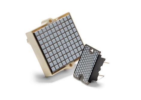
Pre-applied phase change material (PCM) available for easy mounting and handling procedure
Activating the PCM is necessary. For example heatsink must be heated up with cooling liquid or other activation options.
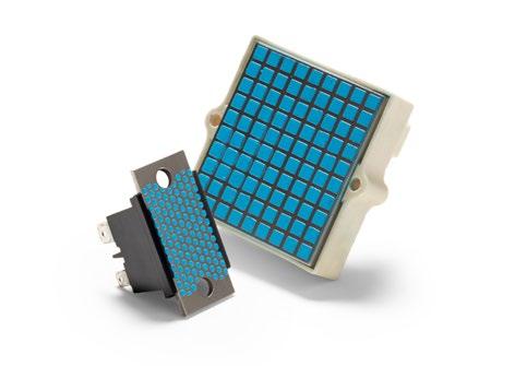
Alternative thermal interface material available – thermal grease (TG)
Requires no activation and comes with ready-touse transportation packaging.
High Voltage Resistors
SGT
SGP / OGP
SHP
SSP / OSP
OSX / SSX / SOX
PHV
MTX 968
MTX 969
MTX 969 W
MTX 967
FBX / FEP / FSX
FPX / FLX
Series SGT
TC of ±25 ppm/°C, US Patent-No. 4,859,981
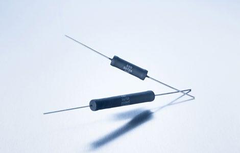
The SGT series meet the most stringent requirements regarding temperature coefficient in connection with high stability performance at high operating voltages. The low temperature coefficient minimizes ohmic value change generated through the warm-up due the power dissipation. Typical applications are medical systems like X-ray, nuclear spin tomography, as well as power supplies or instruments.
Features
up to 48 kV operating voltage
Non-Inductive design
ROHS compliant
Voltages up to 60% higher than the values listed "S-Version“
Technical Specifications
Resistance value 100 KΩ to 1 GΩ (see model specifications)
Resistance tolerance ±1 % to ±10 % standard
±0.1 % to ±0.5 % on special request for limited ohmic values**
Temperature coefficient ±25 ppm/°C referenced to 25°C, ΔR taken at -15°C and +85°C (lower TCR on special request for limited ohmic values)
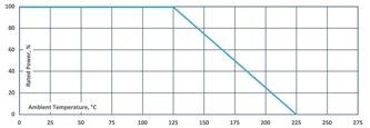
Max. operating temperature + 225 °C
Voltage coefficient -0.2 ppm/V max. as to MIL-Std-202, method 309, 10 kV DC max.
Dielectric strength 1000 V DC
Insulation resistance 10 GΩ min. at 1000 V DC
Overload / overvoltage
5x rated power with applied voltage not to exceed 1.5x maximum continuous operating voltage for 5 s.ΔR 0.20 % max.
Load Life 1000 h at rated voltage not exceeding rated power, typical ΔR (“S”) = 0.1 %, ΔR=0.25 % max.
Load life stability 0.25 % per 1000 h at +125°C
Moisture resistance MIL-Std-202, method 106, ΔR 0.4 % max.
Thermal shock
Encapsulation
Model Specifications
MIL-Std-202, method 107, Cond. B, ΔR 0.20 % max.
standard coating: silicone conformal we recommend 2xpolyimide coating for use in oil and potted applications (ask for details)
Lead material OFHC copper, tin-plated
Weight depending on model no. (ask for details)
How to make a request
Model no._Ohmic Value_Tolerance_TCR
For example: SGT-52 1M 1% 25ppm
Example for higher voltage or optional coating:
SGT-26-S 45M 10% 25ppm or SGT-26 600K 1% 25ppm 2xpolyimide coating
** If you need very tight tolerances (±0.1 % to ±0.5 %), we recommend not to use the full power rating but rather to select the next large size to achieve ultimate stability (ask for detail s)
Series SGT
Series SGP / OGP
TC of ±80 ppm/°C combined with precision tolerances, wide ohmic range / U.S. Patent-No. 4,859,981
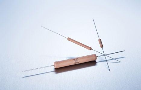
The series employs our special METOXFILM, which demonstrates excellent stability and a wide resistance range. Power and voltage ratings are for continuous operation and have all been pretested for steady-state performance as well as momentary overload conditions.
Features
up to 48 kV operating voltage
Non-Inductive design
ROHS compliant
Voltages up to 60% higher than the values listed –“S“-Version
Technical Specifications
Resistance value 100 Ω to 10 GΩ (see model specifications)
Resistance tolerance ±1 % to ±10 % standard down to ±0.1 % on special request for limited ohmic values
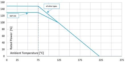
Temperature coefficient
±80 ppm/°C (at +85°C ref. to +25°C) down to ±25 ppm/°C or lower on special request for limited ohmic values and model no.
Max. operating temperature + 225 °C
Voltage coefficient (typical) see diagram
Dielectric strength 1000 V DC max. (25°C, 75 % relative humidity)
Insulation resistance 10 GΩ min. at 1000 V DC
Overload / overvoltage
5x rated power at 125°C (referenced to specified power at +125°C) with applied voltage not to exceed 1.5x maximum continuous operating voltage for 5 s.ΔR 0.5 % max.
Load life 1000 h at 125°C and rated power, components with 1 % tol. ΔR 0.2 % max., extended range (“S”) ΔR = 0.5 % max.
Load life stability typical ±0.02 % per 1000 h
Moisture resistance
MIL-Std-202, method 106, ΔR 0.4 % max.
Thermal shock MIL-Std-202, method 107, Cond. C, ΔR 0.25 % max.
Encapsulation
standard: silicone coating other coating options (like 2xpolyimide, glass) available on request
Other terminals avaiblabe screw end caps [6/32", M4 (torque max. 1 Nm), customer-specific], golden leads with diameter 0,8 mm availabe for SGP series (ask for details)
Lead material OFHC copper, tin-plated
Weight depending on model no. (ask for details)
Dimensions in mm [inches]
Miba Resistors Non-Inductive design offers an outstanding advantage over other techniques. The design incorporates a unique method of DIGITAL TRIMMING to value. Other less desirable methods include an “analog“ method of abrading and removing the resistive material, which frequently results in a weak seation. Miba Resistors patented process avoids this potential problem.
How to make a request
Model.no_Ohmic value_Tolerance_TCR
For example: SGP-103 10M 1% 80ppm or OGP-20 10M 5% 25ppm
Example for high voltage: SGP-154-S 300M 2% 80ppm or OGP-39-S 100M 1% 25ppm
High-Voltage Resistors
Series SGP / OGP
Model Specifications
** Our resistors are designed for operation in air and non-aggressive atmosphere. For special applictions like oil, casting, molding, SF6, etc., please contact us.
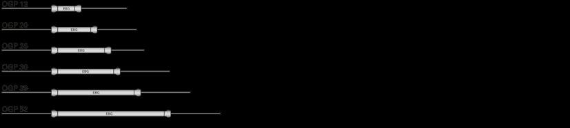
OGP series overview
SGP series overview
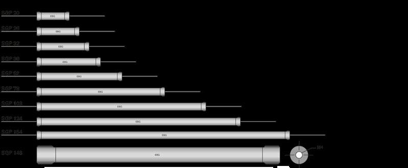
All SGP and SGT types (except 148) are also available with M4 oder 6/32 screw end caps. Attention: total length increases when screw end caps are used!
No coating on end areas!
High-Voltage Resistors
Series SGP / OGP
Typical Voltage Coefficient for SGP series (in ppm per volt)
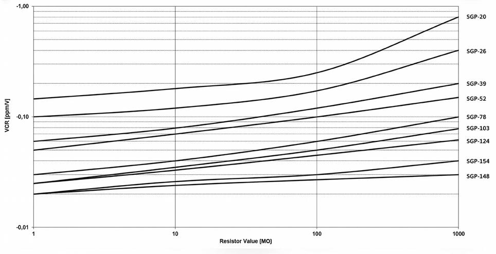
Example: SGP-154 with 100 MΩ has a typical voltage coefficient of -0,03 ppm/V.
Ultra-High Precision Resistor
Series SHP
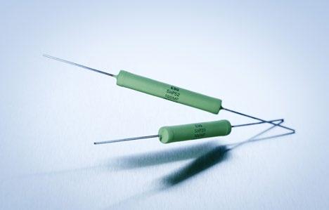
Overall stability ±5 ppm/°C from +25°C to +65°C (incl. VCR & TCR)
We developed new material combinations and processing methods which make it possible to achieve a TCR (thermal coefficient of resistance) of up to ±5 ppm while maintaining the minimal VCR (voltage coefficient of resistance).
Features
up to 15 kV operating voltage
Non-Inductive design
ROHS compliant
Technical Specifications
Resistance value 100 MΩ to 250 MΩ (other values on special request)
Resistance tolerance ±1 % standard (lower on special request for limited ohmic values)
Temperature coefficient ±5 ppm/°C from +25°C to +65°C in 10 degree steps (incl. VCR & TCR) referenced to 25°C
Operating working voltage 10 kV DC
Dielectric strength ≤ 10 kV DC based on the coating
Insulation resistance 10 GΩ min. at 1000 V DC
Power rating up to 1 W
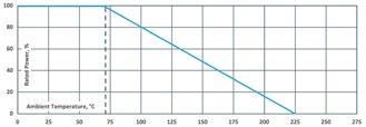
Load life 1000 h at rated power at 70°C, ΔR 0.20 % max.
Load life stability 0.20 % per 1000 h at 70°C
Moisture resistance
MIL-Std-202, method 106, ΔR 0.4 % max.
Thermal shock MIL-Std-202, method 107, Cond. A, ΔR 0.20 % max.
Encapsulation
Model Specifications
standard coating: silicone conformal we recommend 2xpolyimide coating for use in oil and potted applications (ask for details)
Lead material OFHC copper, tin-plated
Weight depending on model no. (ask for details)
How to make a request
Model no._Ohmic value_Tolerance
For example: SHP-52 150M 1%
Dimensions in mm [inches]
Series SSP / OSP
Power- and High-Voltage Resistors with high maximum temperature operation, TC of ±50 ppm/°C
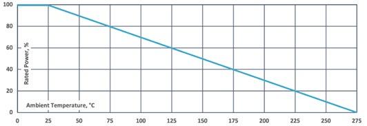
The SSP series meets the requirements of power ratings of up to 40 W while at the same time offering voltage ratings of up to 6,000 V. These Power Resistors cover a wide ohmic value range and operate at up to 275°C in axial lead construction.
Features
up to 40 kV operating voltage
Non-Inductive design
ROHS compliant
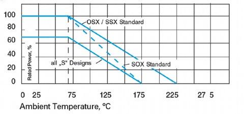
Full power and voltage ratings (derating not required)
Technical Specifications
Resistance value 0.1 Ω to 30 MΩ (see model specifications)
Resistance tolerance ±1 % to ±10 % standard ±0.1 % to ±0.5 % on special request for limited ohmic values** - "L -Version"
Temperature coefficient
≥ 10 Ω: 50 ppm/°C
(referenced to 25°C, ΔR taken at -15°C and +85°C) 25 ppm/°C on special request for limited ohmic values, ask for details
Max. operating temperature + 275°C
Dielectric strength 1000 V DC
Insulation resistance 10 GΩ min. at 1000 V DC
Overload / overvoltage
5x rated power with applied voltage not to exceed 1.5x maximum continuous operating voltage for 5 s.ΔR 0.5 % max. or 0.5 Ω max. whichever is greater (not applicable for SSP-148!)
Load Life 1000 h at rated power, ΔR 0.5 % max. or 0.5 Ω max., whichever is greater
Thermal shock MIL-Std-202, method 107, Cond. C, ΔR 0.5 % max. or 0.5 Ω max., whichever is greater
Encapsulation standard coating: silicone conformal we recommend 2xpolyimide coating for use in oil and potted applications (ask for details) other coatings available on special request
Lead material OFHC copper, tin-plated
Other terminals available screw end caps [6/32", M4 (torque max. 1 Nm), customer-specific], golden leads with diameter 0,8 mm availabe for SSP series (ask for details)
Model Specifications
Weight depending on model no. (ask for details)
To accomplish this objective of high stability, high value, high voltage and high power in the SSP series, Miba Resistors employs a special variation of its METOXFILM formulations. These films are annealed on special ceramic bodies at temperatures above 1,400°F/800°C and become an inherent part of the ceramic surface, which brings about their unusual performance characteristics. As a result of Miba Resistors unique Non-Inductive patented process, these resistors are ideally suited for high-frequency applications and result in less “ringing” with minimum distortion of the signals and faster settling times.
F*: enforced cooling
- Resistor in open air position, air flow >1.5 m/s. at ≤25°C ambient temperature
- Resistor in case, air flow >2 m/s. at ≤25°C ambient temperature
** Version L:
Resistance tolerances down to ±0.5 % or ±0.1 %, lower max. power (like SGP Series)
Cylindrical Power Resistors
Series SSP / OSP
OSP series overview
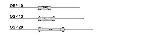
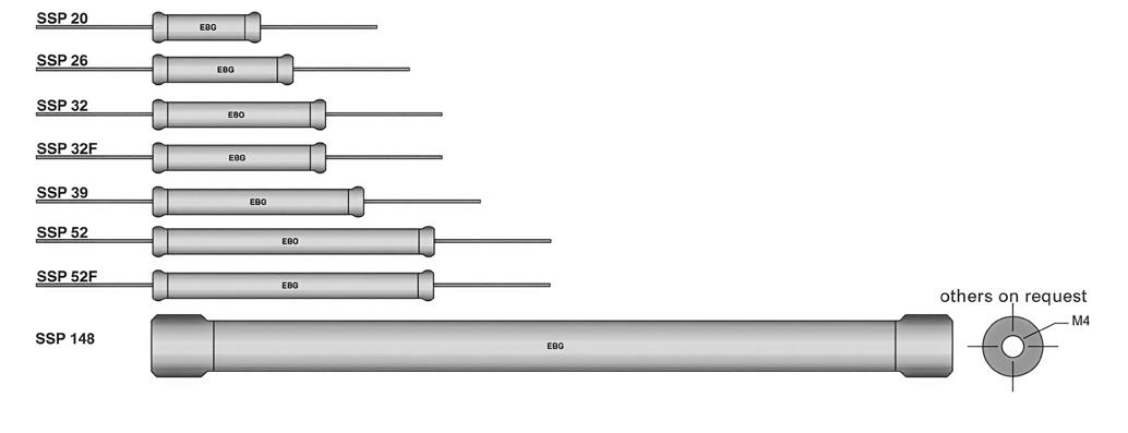
SSP series overview
How to make a request
Model no._Ohmic Value_Tolerance_TCR
For example:
SSP-52 68R 5% 50ppm or OSP-10 150K 10% 50ppm
Example for low tolerance
SSP-32-L 10R04 0.1% 50ppm
Dimensions in mm [inches]
38.1 +3.18 (1.5 +0.125)
Cylindrical Power Resistors
Series SSP / OSP
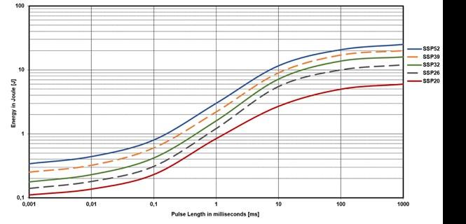
Pulse Energy Curve (typical rating for SSP series)
Note: These energy values are reference values → depending on ohmic value e.g. 1 Ω to 10 Ω and used resistive paste, a variation in max. energy load capability is possible
Test procedure
Every test resistor was mounted with brackets in free air at +25°C ambient temperature
The test time of each tested resistor: 10min.
Break time between two pulses: 1s.
To determine good / defect parts the ohmic value was measured before and after tests: a change of tolerance of more than 0.1% means defect
Example
Description of Pulse Energy Curve
Shape of pulse = e-function
Time between two pulses = 1 second
Pulse length = time constant of 1 tau (1 means ... tau = 1ms)
At 1 ms tau the SSP-52 with e.g. 1 Ω to 10 Ω can withstand an energy level of about 3 J, when the pulse pause time is ≥ 1s
Pulse Power Curve (typical rating for SSP series)
The power curve shows the max. possible power which can be applied for a certain duration. Referring to the same test procedure as described above.
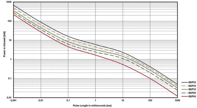
Description of Pulse Power Curve
Shape of pulse = e-function
Time between two pulses = 1 second
Pulse length = time constant of 1 tau (1 means ... tau = 1ms)
Example For SSP-52 the time-constant of 1 ms you can apply about 6 kW max., if the time between two such peaks is ≥ 1s
Precision High-Voltage Resistors
Series OSX / SSX / SOX
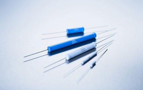
Power- and Precision High-Voltage Resistors TC of ±100 ppm/°C and wide ohmic range
The OSX/SSX/SOX series meets a general set of requirements. The products are available with a silicone or epoxy coating and feature a wide range of tolerances and temperature coefficients.
Features
up to 60 kV operating voltage
Non-Inductive design
ROHS compliant
Full encapsulation over the entire resistor length
All SSX types are available with M4 or 6/32 screw end caps
Technical Specifications
Resistance value
Resistance tolerance
Temperature coefficient
100 Ω to 50 GΩ (see model specifications) higher values on special request
±1 % to ±10 % standard
±0.1 % to ±0.5 % on special request for limited ohmic values*
100 ppm/°C standard (+85°C ref. to +25°C) down to ±5 ppm/°C on special request for limited ohmic values and tolerances
Max. working voltage see model specifications
Power Rating up to 19.40 W (see model specifications)
Dielectric strength ≤ 10 kV DC based on the coating
Overload / overvoltage
Load life stability
Moisture resistance
Thermal shock
Encapsulation
5x rated power at 70°C (referenced to specified power at +70°C) with applied voltage not to exceed 1.5x maximum continuous operating voltage for 5 s.ΔR 0.5 % max.
1000 h at rated power at 70°C, ΔR 0.20 % max.
MIL-Std-202, method 106, ΔR 0.4 % max.
MIL-Std-202, method 107, Cond. A, ΔR 0.20 % max.
silicone or epoxy coating standard coatings: silicone or epoxy coating we recommend 2xpolyimide coating for use in oil and potted applications but with reduced dielectric strength (ask for details)
Other terminals avaiblabe screw end caps (6/32", M4, custom), golden leads with diameter 0,8 mm availabe for SSX / SOX series (ask for details)
Lead material OFHC copper, tin-plated Weight depending on model no. (ask for details)
* In case of very tight tolerances (±0.1 % to ±0.5 %) we suggest not to use the full power rating, but rather the next larger size to achieve ultimate stability (contact us for details)
Dimensions in mm [inches]
Different coatings available:
- Series OSX: silicone coating for ambient temperatures up to 225°C
- Series SOX: epoxy coating for excellent humidity protection
- Series SSX: silicone coating for ambient temperatures up to 225°C
Other coating options such as glass, 2xpolyimide, UV cured, on special request
How to make a request
Model no._Ohmic Value_Tolerance_TCR
For example: OSX-39 100M 0.5% 100ppm or SSX-39 500K 10% 50ppm
Example for higher working voltage: SOX-78-S 500M 0.5% 25ppm
Series OSX / SSX / SOX
Model Specifications
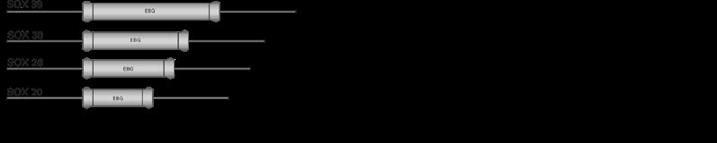
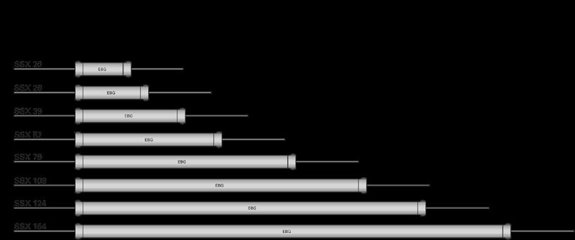
SOX series overview SSX series overview
** Our resistors are designed for operation in air and nonaggressive atmosphere. For special applications like oil, casting, molding, SF6, etc., please contact us.
*** higher ohmic values on special request (ask for details) 2/2
High-Voltage Resistors
Series PHV
Surge test up to 325 kV (1.2/50 µs) under potting surrounding
Features
up to 60 kV operating voltage
Non-Inductive design
ROHS compliant
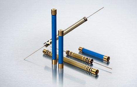
Technical Specifications
Resistance value 500 Ω to 1 GΩ (other values on special request)
Resistance tolerance ±1 % to ±10 %
Temperature coefficient ±100 ppm/°C from +25°C to +85°C (down to ±15ppm possible, ask for details))
Operating working voltage 60 kV DC
Dielectric strength ≤ 10 kV DC based on the coating
Insulation resistance 10 GΩ min. at 1000 V DC
Power rating see model specifications below
Load life 1000 h at rated power at 70°C, ΔR 0.20 % max.
Load life stability 0.20 % per 1000 h at 70°C
Moisture resistance MIL-Std-202, method 106, ΔR 0.4 % max.
Thermal shock MIL-Std-202, method 107, Cond. A, ΔR 0.20 % max.
Encapsulation 2xpolyimide coating for use in oil and potted applications (other coating options available. ask for details)
Lead material OFHC copper, tin-plated
Other terminals available screw end caps (6/32", M4, custom), golden leads with diameter 0,8 mm available
Model Specifications
Weight depending on model no. (ask for details)
How to make a request
Model no._Ohmic value_Tolerance_TCR
For example: PHV-52 150M 10% 100ppm
Series MTX 968
Ohmic range (400 Ω - 30 GΩ), up to 54 kV operating voltage
The MTX 968 resistor series is designed for use in voltage dividers, medical equipment, electrostatic devices, measuring equipment and current limiting devices where high stability, low TCR, high ohmic values and high shortterm loads are required.
Features
up to 54 kV operating voltage
Tolerance range ±0.1% to ±10 %
Ohmic range 400 Ω to 30 GΩ
Non-Inductive design
ROHS compliant
Technical Specifications
Resistance value 400 Ω to 30 GΩ (see model specifications)
Resistance tolerance ±0.1 % to ±10 %
Temperature coefficient ±15 ppm/°C to ±200 ppm/°C (at +85°C ref. to + 25°C) lower TCR on special request for limited ohmic values
Max. Operating temperature -55°C to +225°C
Dielectric strength > 1000 V (25°C, 75% relative humidity)
Load life ΔR/R 0.5% max., 1000 h at rated power
Moisture resistance ΔR/R 0.25% max.
Thermal shock ΔR/R 0.25% max.
Encapsulation
Model Specifications
standard coating: silicone conformal (A) we recommend 2xpolyimide coating (P) for use in oil and potted applications (ask for details) other coatings available on special request
Lead material copper wire, gold-plated
Weight depending on model no. (ask for details)
How to make a request
Model no._Ohmic Value_Tolerance_TCR
For example: MTX 968.3 36M 10% 100ppm
Example for optional coating: MTX 969.15 100M 1% 100ppm 2xpolyimide coating
Our resistors are designed for operating in air and non-aggressive atmospheres. For special applications (i.e. oil, casting, molding, SF6, etc.), please contact our local EBG representative or contact us directly.
For further options please contact your local Miba Resistors representative.
Miba
Precision High-Voltage / High Power Resistors
Series MTX 969
Up to 96 kV and 105 W
The MTX 969 resistor series is designed for use in voltage dividers, medical equipment, electrostatic devices, measuring equipment and current limiting devices where high stability, low TCR, high ohmic values and high shortterm loads are required.
Features
up to 96 kV operating voltage
Tolerance range ±0.1% to ±10 %
Ohmic range 2 Ω to 25 GΩ
Non-Inductive design
ROHS compliant
Technical Specifications
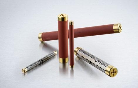
Resistance value 2 Ω to 25 GΩ (see model specifications)
Resistance tolerance ±0.1 % to ±10 %
Temperature coefficient ±10 ppm/°C to ±200 ppm/°C (at +85°C ref. to + 25°C) lower TCR on special request for limited ohmic values
Max. Operating temperature -55°C to +225°C
Dielectric strength > 1000 V (25°C, 75% relative humidity)
Load life ΔR/R 0.5% max., 1000 h at rated power
Moisture resistance ΔR/R 0.25% max.
Thermal shock ΔR/R 0.25% max.
Encapsulation
Model Specifications
standard coating: silicone conformal we recommend 2xpolyimide coating for use in oil and potted applications (ask for details) other coatings available on special request
Lead material caps, bare brass
Torque 1.8 Nm to 2 Nm for M4, 3.8 Nm to 4 Nm for M8
Weight depending on model no. (ask for details)
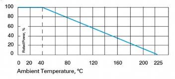
How to make a request
Model no._Ohmic Value_Tolerance_TCR
For example: MTX 969.105 12M 10% 100ppm
Example for optional coating MTX 969.71 100M 0.1% 100ppm 2xpolyimide coating
Dimensions in mm
High-Power Water-Cooled Resistors
Series MTX 969 W
High-Power Water-Cooled Single Resistors and Voltage Dividers up to 1700 W
Our resistor series 969 W is designed for use in high-power applications. Direct water cooling renders these resistors suitable for a very high continuous power load.
Easy M4 mounting, wide ohmic range, precise tolerance and temperature coefficient values as well as high dielectric strength capability are only some of the features of this resistor series. There is also an option for voltage dividers!
Features
up to 1700 W operating power
Non-Inductive design
ROHS compliant
Technical Specifications
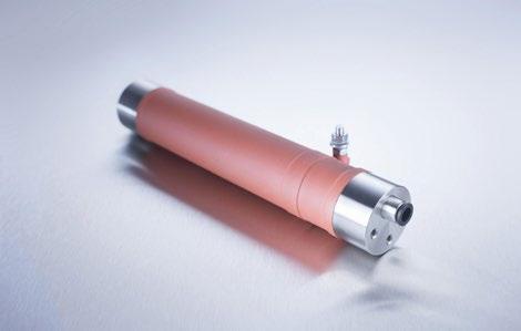
value 0.5 Ω to 10 MΩ
Resistance tolerance ±5 % to ±10 % standard
Temperature coefficient > 10 Ω: ±100 ppm/°C standard ≤ 10 Ω: +250 ppm/°C (at +85°C ref. to +25°C) lower TCR on special request for limited ohmic values
Inductivity 80 – 100 nH typical measuring frequency 10 kHz
Isolation voltage 10 kV DC (between Contact 1 and Isolation Contact) – for 969 W and 969 W-L 3 kV DC for 969 W-S
Connecting type of cooling medium 6 mm – tube (other connections on special request)
Max. cooling medium pressure 10 bar
Contact material CrNi (stainless)
Weight depending on model no. (ask for details)
(max. Power at cooling medium temp. < 50°C, flow > 7 l / min.)
If (power-) resistors are used in an enforced cooling application, coolant flow may not be interrupted!
Isolation Contact
How to make a request
Model no._Ohmic Value_Tolerance
For example:
High-Voltage Flat Style Resistors
Series MTX 967
TC of ±10 ppm/°C to ±200 ppm/°C, different coatings available
Good temperature and voltage coefficients, high resistance values and high voltage capability.
Features
up to 35 kV operating voltage
Tolerance range ±10 % to ±0.1 %
Ohmic range 10 Ω to 30 GΩ (depending on model no.)
Non-Inductive design
ROHS compliant
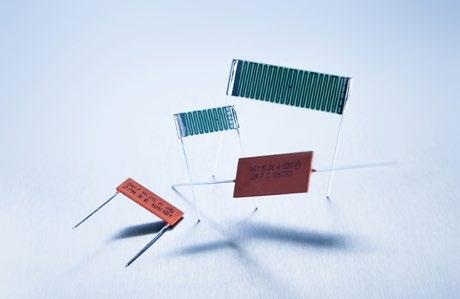
Technical Specifications
Resistance value 10 Ω to 30 GΩ (depeding on model no., ask for details)
Resistance tolerance ±0.1 % to ±10 %
Temperature coefficient ±15 ppm/°C to ±200 ppm/°C (at 85°C ref. to +25°C) other TCR on special request for limited ohmic values
Max. operating temperature -55 to +175°C
Dielectric strength > 1000 V (25°C, 75% relative humidity)
Insulation resistance > 10,000 M (500 V, 25°C, 75% relative humidity)
Overload ΔR/R 0.25 % max. 1.5x Pnom, 5 s. (do not exceed 1.5x V max.)
Load Life ΔR/R 0.25 % max.
Moisture resistance ΔR/R 0.25 % max.
Thermal shock ΔR/R 0.2 % max.
Encapsulation silicone conformal (U) or glass coating (G) other coatings with different dielectric strengths available on special request
Lead material tinned copper
Weight depending on model no. (ask for details)
Model Specifications
Dimensions in mm
How to make a request
Model no. A or R_U or G_Ohmic Value_ Tolerance_TCR
A = Axial R = Radial
U = Silicone conformal coating G = Glass coating
For example: MTX 967.3.25 RG 56M 5% 100ppm or MTX 967.15.15 AU 1G 1% 100ppm (inches)
*Pins: L = 9 + 1 mm 0.6 x 0.35 mm
High-Voltage
Series FBX / FEP / FSX
TC of ±80 ppm/°C combined with precision tolerances and wide ohmic range
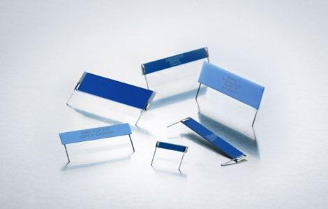
Low-cost, high-voltage resistors that provide high-density packaging in large volume applictions.
Features
up to 29 kV operating voltage
Non-Inductive design
ROHS compliant
Standard contact lead diameter 0.6 mm. Others available on special request or no lead version for SMD mounting
On request custom designed version available, max. ceramic size substrates 101.6 mm (4 inch)
Voltages up to 35% higher than the values listed –“S“-Version
Technical Specifications
Resistance value
200 Ω to 2 GΩ higher values on special request
Resistance tolerance ±0.5 % to ±10 % down to ±0.1 % on special request for limited ohmic values
Temperature coefficient
≤ 100 MΩ: ±80 ppm/°C standard > 100 MΩ: ±150 ppm/°C standard from -5°C to +105°C referenced to +25°C; down to 15ppm/°C on special request for limited ohmic value
Max. operating temperature FBX/FEP/FSX: -55°C to +225°C
Voltage coefficient see VCR-chart below, for FBX-6/5 ask for details
Weight depending on model no. (ask for details)
Different coatings available:
- Series FBX: with surface silicone print as an inexpensive alternative
- Series FEP: surface epoxy print
- Series FSX: silicone conformal for hightempearture operations (225°C)
Other coating options such as glass, 2xpolyimide, UV cured, on special request
Model Specifications
Series FBX with Surface Silicone Print
Series FBX / FEP / FSX
Series FSX with Conformal Silicone
How to make a request Model no._Ohmic value_Tolerance_TCR
For example:
Typical Voltage Coefficient for FBX series (in ppm per volt) Example:
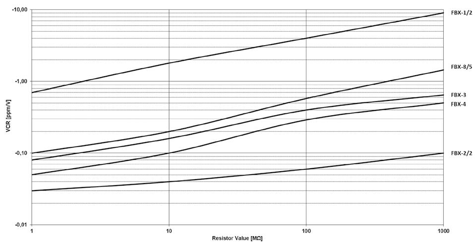
with 100 MΩ has a typical voltage coefficient of -0.06 ppm/V.
Series FPX / FLX
TC of ±100 ppm/°C combined with precision tolerance and wide ohmic range
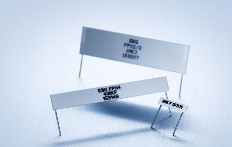
Low-cost power resistors that provide high-density packaging in large volume applications.
Features
up to 22 kV operating voltage
Series FPX / FLX printed silicone surface protection or conformal silicone coating for high-temperature operation (225°C)
Thickness max. 3 mm (0.118 inch) for high-density packaging
Non-Inductive design
ROHS compliant
Voltages up to 35% higher than listed = "S"-Version
Technical Specifications
Temperature coefficient ±100 ppm/°C, measured from +25°C to 85°C on special request down to ±15 ppm
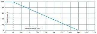
Model Specifications
Series FLX with Conformal Silicone Protection
How to make a request
Model no._Ohmic Value_Tolerance
For
Power Resistors
LXP-30 TO-220
LXP-100 B TO-247
LXP-150 TO-247
LHP-150 TO-247
MXP 35 TO-220
MSP 35 SMD TO-220
SC-55 TO-263
AXP-50
AXP-100 B
AXP-150
AXS-600 / AXF-600 / AXP-600
GXP 120, SOT-227
HPP 150
VHP
HPS 150
HXP 200, SOT-227
HXP 600
PXP 200, SOT-227 (solder pin)
LPP 250
WLL 320
ACP 100
AXM
RPS 100
Series LXP-30 TO-220
30 W Thick Film Resistor designed for high-frequency and pulse-loading applications.
Miba Resistor offers the totally encapsulated and insulated TO-220 package for low ohmic value and Non-Inductive design for high-frequency and pulse-loading applications. Ideal use for power supplies. The LXP-30 series is rated at 30 W mounted to a heat sink.
Features
30 W operating power
TO-220 package configuration
Single-screw mounting simplifies attachment to heat sink
A totally Wed housing for enviromental protection
Fully isolated heat sink
Non-Inductive design
Pulse load capability
Technical Specifications
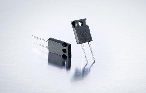
Resistance value 0.05 Ω to 1 MΩ (other values on request)
Resistance tolerance ±1 % to ±10 % ±0.5 % on special request for limited ohmic values
Temperature coefficient >10 Ω ±50 ppm/°C 1 Ω to 10 Ω ±100 ppm/°C + 0.002 Ω (referenced to 25 °C, ΔR taken at ~105°C)
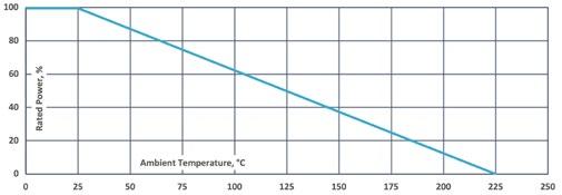
Power rating 30 W at 25°C bottom case temperature depends on case temperature (see power rating curve)
Operating Voltage 420 V
Dielectric strength 1800 V AC
Insulation resistance > 10 GΩ at 1000 V DC
Short time overload 2x rated power with applied voltage not to exceed 1.5x maximum continuous operating voltage for 5 s. ΔR ±(0.3 % + 0.001 Ω) max.
Load life MIL -R-39009D, 2000 h at rated power, ΔR ±(1.0 % + 0.001 Ω) max.
Moisture resistance
Thermal shock
Terminal strength
Vibration, high frequency
MIL -STD-202, method 106 ΔR ±(0.5 % + 0.001 Ω) max.
MIL -STD-202, method 107, Cond. F, ΔR ±(0.3 % + 0.001 Ω) max.
MIL -STD-202, method 211, Cond. A (Pull Test) 2.4 N, ΔR ±(0.2 % + 0.001 Ω) max.
MIL -STD-202, method 204, Cond. D, ΔR ±(0.2 % + 0.001 Ω) max.
Lead material anti-oxidation tinned copper wire
Mounting M3 screw, max. torque 0.9 Nm
Working temperature -55 °C to +150 °C
Dimensions in mm [inches]
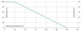
Derating (thermal resist.) LXP-30: 0.24 W/K (4.17 K/W)
Without a heat sink, when in open air at 25°C, the LXP-30 is rated for 2.25 W. Derating for temperature above 25°C is 0.018 W/K.
In case temperature is to be used for the definition of the applied power limited. The case temperature measurement must be made with a thermocouple contacting the center of the component mounted on the designed heat sink. Thermal grease should be applied properly.
How to make a request
LXP-30_Ohmic Value_Tolerance
For example: LXP-30 50R 5%
Series LXP-100 B TO-247
100 W Thick Film Resistor for high-frequency and pulse-loading applications
Version B for enforced mechanical stability 1/3
Miba Resistors offers the completely encapsulated and insulated TO-247 package for low ohmic value and Non-Inductive design for high-frequency and pulse-loading applications. Ideal use for power supplies. The LXP-100 B series is rated at 100 W mounted to a heat sink.
Features
100 W operating power
TO-247 package configuration
Single-screw mounting simplifies attachment to heat sink
A fully molded housing for environmental protection
Resistor package completely insulated from heat sink
Tube packing available (packing unit: 35 pcs. / tube)
For perfect heat dissipation, the use of mounting clamps is suggested (ask for details)
Non-Inductive design
ROHS compliant
Materials in accordance with UL 94 V-0
Technical Specifications
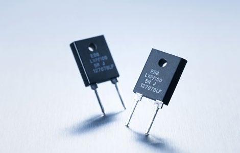
Resistance value 0.05 Ω to 1 MΩ (other values on special request)
Resistance tolerance ±10 % to ±1 %
Temperature coefficient > 10 Ω: ±50 ppm/°C referenced to 25°C, ΔR taken at +105°C (other TCR on special request for limited ohmic values)
Power rating 100 W at 25°C bottom case temperature derated to 0 W at 175°C
Short time overload
1.5x rated power with applied voltage not to exceed 1.5x V max. for 5 s.onds, ΔR < ±(0.50 % + 0.0005 Ω)
Operating voltage 350 V, max. 500 V on special request
Insulation resistance > 10 GΩ at 1000 V DC
Dielectric strength voltage 1800 V AC
Dieletric strength
Load life
Moisture resistance
Thermal shock
Terminal strength
Vibration, high frequency
MIL -STD-202, method 301 (1,800 V AC, 60 s.)
ΔR < ±(0.15 % + 0.0005 Ω)
MIL -R-39009D 4.8.13,
2000 h at rated power, ΔR < ±(1.0 % + 0.0005 Ω)
-10°C to +65°C, RH > 90 % cycle 240 h, ΔR < ±(0.50 % + 0.0005 Ω)
MIL -STD-202, method 107, Cond. F, ΔR < ±(0.50 % + 0.0005 Ω)
MIL -STD-202, method 211, Cond. A (Pull Test) 2.4 N ΔR < ±(0.20 % + 0.0005 Ω)
MIL -STD-202, method 204, Cond. D, ΔR < ±(0.40 % + 0.0005 Ω)
Inductance (serial) typical 20 nH, measuring frequency 10 kHz
Lead material tinned copper
Mounting 0.7 Nm to 0.9 Nm M4 using a M3 screw and a compression wahser mounting technique
Weight ~4 g
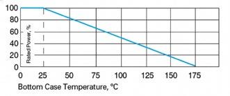
Derating (thermal resist.) LXP-100 B: 0.66 W/K (1.5 K/W)
Without a heat sink, when in open air at 25°C, the LXP-100 B is rated for 3 W. Derating for temperature above 25°C is 0.023 W/K.
Case temperature must be used for definition of the applied power limit. Case temperature measurement must be done with a thermocouple contacting the center of the component mounted on the designed heat sink. Thermal grease should be applied properly.
This value is only applicable when using thermal conduction to heat sink Rth-cs <0.025 K/W. This value can be attained by using a thermal transfer compound with a heat conductivity of 1 W/mK. The flatness of the cooling plate must be bettern than 0.05 mm overall. Surface roughness should not exceed 6.4 µm.
How to make a request
LXP-100 B_Ohmic Value_Tolerance
For example: LXP-100 B 20R 10%
Series LXP-100 B TO-247
AECQ200 ready
longer contacts availabe (ask for details)
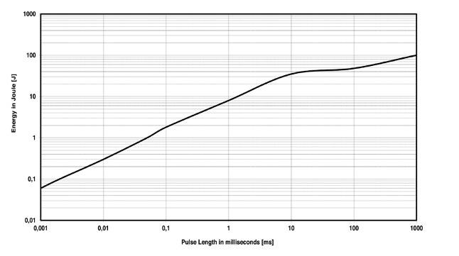
Pulse Energy Curve (typical rating for LXP-100 B)
Note: These energy values are reference values -> depending on ohmic value and used resistive paste, a variation in max. energy load capability is possible
Test procedure
Every test resistor was mounted with thermal compound (0.9 W/mK) on a water cooled heatsink
Constant inlet water temperature: +50°C
The test time of each tested resistor: 10min.
Break time between two pulses: 1s.
To determine good / defect parts the ohmic value was measured before and after tests: a change of tolerance of more than 0.1% means defect
Example
Description of Pulse Energy Curve
Shape of pulse = e-function
Time between two pulses = 1 second
Pulse length = time constant of 1 tau (1 means ... tau = 1ms)
At 1 ms tau the LXP-100 B can withstand an energy level of about 8 J, when the pulse pause time is ≥ 1s
At a symmetrical frequency > 1 kHz at pulse length ≥ 10 µs. the maximum applied pulse energy for LXP-100 B is an result out of the normal power 100 W divided by the operating frequency (at 25°C bottom case) (E = 100 W / F)
Power Resistors
Series LXP-100 B TO-247
Pulse Power Curve (typical rating for LXP-100 B)
The power curve shows the max. possible power which can be applied for a certain duration. Referring to the same test procedure as described at page 35.
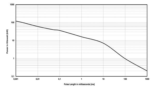
Description of Pulse Power Curve
Shape of pulse = e-function
Time between two pulses = 1 second
Pulse length = time constant of 1 tau (1 means ... tau = 1ms)
Example For the time-constant of 1 ms you can apply about 16 kW max. (Pp = 2*E / τ)à, if the time between two such peaks is ≥ 1s
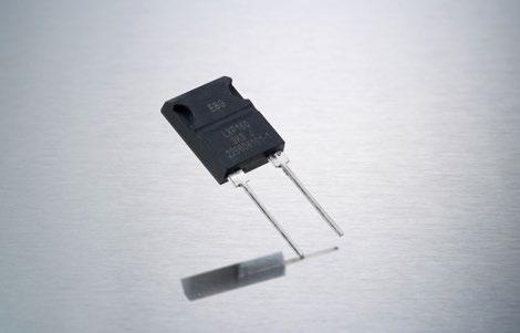
Series LXP-150 TO-247
150 W Thick Film Resistor for high-frequency and pulse-loading applications
AECQ200 ready
Miba Resistors offers the completely encapsulated and insulated TO-247 package for low ohmic value and NonInductive design for high-frequency and pulseloading applications. Ideal use for power supplies. The LXP-150 series is rated at 150W mounted to a heat sink.
Features
150 W operating power
TO-247 package configuration
Clip mounting simplifies attachment to heat sink
Non-Inductive design
Technical Specifications
Resistance value 0.2 Ω to 1 MΩ
Resistance tolerance ±1 % to ±10 % ±0.5 % on special request for limited ohmic values
Temperature coefficient > 10R: ±50 ppm/°C referenced to 25°C, ΔR taken at +105°C (other TCR on special request for limited ohmic values)
Power rating 150 W at 25°C bottom case temperature
Maximum operating voltage 700 V DC
Dielectric strength 1800 V AC
Insulation resistance min. 10 GΩ
Momentary overload 2 times rated power, but no more than 1.5 time max. continuous operating voltage, last 5s, ΔR ≤ ±(0.3%R + 0.001Ω)
Load life 2000 h at rated power, MIL-R-39009D ΔR ≤ ±(1.0%R + 0.001Ω)
Moisture resistance
Thermal schock
Terminal strength
Vibration, high frequency
MIL-Std.-202, method 106, ΔR ≤ ±(0.5%R + 0.001Ω)
MIL-Std.-202, method 107, Cond. F ΔR ≤ ±(0.3%R + 0.001Ω)
MIL-Std.-202, method 211, Cond. A (pull test) 2.4 N ΔR ≤ ±(0.2%R + 0.001Ω)
MIL-Std.-202, method 204, Cond. D ΔR ≤ ±(0.2%R + 0.001Ω)
Working temperature -55°C to +175°C
Lead material tinned copper Weight ~4,2 g
Dimensions in mm [inches]
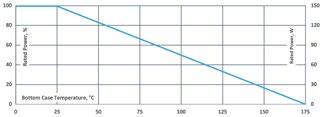
Derating (thermal resist.) LXP-150: 1.00 W/K (1.0 K/W)
Without a heat sink, when in open air at 45°C, the LXP-150 is rated for 4.5 W.
How to make a request
LXP-150_Ohmic Value_Tolerance
For example: LXP-150 50R 5%
Application Standard
IEC60115-1 : 2001 (GB/T5729-2003)
MIL-STD-202
MIL-R-39009D
Series LHP-150 TO-247
150 W Thick Film Resistor for high-frequency and pulse-loading applications 1/1 Power
Miba Resistors offers the completely encapsulated and insulated TO-247 package for low ohmic value and Non-Inductive design for high-frequency and pulse-loading applications. Ideal use for power supplies. The LHP-150 series is rated at 150 W mounted to a heat sink.
Features
150 W operating power
TO-247 package configuration
Resistor package completely insulated from heat sink
Non-Inductive design
Technical Specifications
Resistance value 0.2 Ω to 1 MΩ
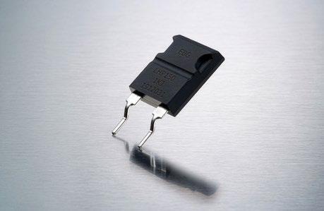
Resistance tolerance ±5 % to ±10 % ±0.5 % on special request for limited ohmic values
Temperature coefficient ±150 ppm/°C (+25°C to +105°C, ref. to +25°C)
Power rating 150 W at 25°C bottom case temperature
Maximum operating voltage 700 V DC
Dielectric strength 1800 V AC
Insulation resistance min. 10 GΩ
Momentary overload
2 times rated power, but no more than 1.5 time max. continuous operating voltage, last 5s, ΔR ≤ ±(0.5%R + 0.001Ω)
Load life 2000 h at rated power, MIL-R-39009D ΔR ≤ ±(1.0%R + 0.001Ω)
Moisture resistance
Thermal schock
Terminal strength
Vibration, high frequency
MIL-Std.-202, method 106, ΔR ≤ ±(0.5%R + 0.001Ω)
MIL-Std.-202, method 107, Cond. F ΔR ≤ ±(0.3%R + 0.001Ω)
MIL-Std.-202, method 211, Cond. A (pull test) 2.4 N ΔR ≤ ±(0.2%R + 0.001Ω)
MIL-Std.-202, method 204, Cond. D ΔR ≤ ±(0.2%R + 0.001Ω)
Working temperature -55°C to +175°C
Lead material tinned copper
Weight ~4 g
Dimensions in mm [inches]
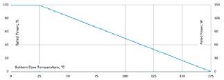
Derating (thermal resist.) LHP-150: 1.00 W/K (1.0 K/W)
Without a heat sink, when in open air at 45°C, the LHP-150 is rated for 4.5 W.
How to make a request
LHP-150_Ohmic Value_Tolerance
For example: LHP-150 50R 5%
Application Standard
IEC60115-1 : 2001 (GB/T5729-2003)
MIL-STD-202
MIL-R-39009D
Soldering Note:
During surface mount soldering, the soldering temp. profile must not cause the metal tab of this device to exceed 245°C
Soldering Template
Power Resistors
Series MXP 35 TO-220
35 W Thick Film Resistor for high-frequency and pulse-loading applications
Features
35 W operating power
TO-220 package configuration
Single-screw mounting simplifies attachment to heat sink
Molded case for environmental protection
Resistor element is electrically insulated from the metal sink tab
Standard lead form for easier fit
Non-Inductive design
ROHS compliant
Materials in accordance with UL 94 V-0
Technical Specifications
1/2
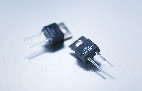
Resistance value 0.05 Ω to 1 MΩ (other values on special request)
Resistance tolerance ±1 % to ± 10 %
±0.5 % on special request for limited ohmic values
Temperature coefficient < 3 Ω: ask for details ≥ 3 Ω < 10 Ω: ±100 ppm + 0.002 Ω/°C ≥ 10 Ω: ±50 ppm/°C (referenced to 25 °C, ΔR taken at +85°C)
Power rating 35 W at 25°C bottom case temperature
Maximum operating voltage 350 V
Dielectric strength voltage 1800 V AC
Insulation resistance > 10 GΩ at 1000 V DC
Momentary overload
Load life
Moisture resistance
Thermal shock
2x rated power with applied voltage not to exceed 1.5x maximum continuous operating voltage for 5 s. ΔR ±(0.3 % + 0.01 Ω) max.
MIL -R-39009, 2000 h at rated power, ΔR ± (1.0 % + 0.01 Ω) max.
MIL -STD-202, method 106 ΔR = (0.5 % + 0.01 Ω) max.
MIL -STD-202, method 107, Cond. F, ΔR = (0.3 % + 0.01 Ω) max.
Working temperature range -55 °C to +175 °C
Terminal strength
Vibration, high frequency
MIL -STD-202, method 211, Cond. A (Pull Test) 2.4 N, ΔR = (0.2 % + 0.01 Ω) max.
MIL -STD-202, method 204, Cond. D, ΔR = (0.2 % + 0.01 Ω) max.
Lead material tinned copper
Torque 0.7 Nm to 0.9 Nm
Heat resistance to cooling plate Rth < 4.28 K/W
Weight ~2 g
Dimensions in mm [inches]
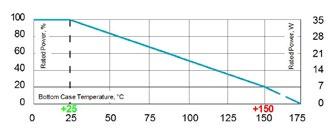
Derating (thermal resist.) MXP-35: 0.23 W/K (4.28 K/W)
Without a heat sink, when in open air at 25°C, the MXP-35 is rated for 2.50 W. Derating for temperature above 25°C is 0.02 W/K.
Case temperature must be used for definition of the applied power limit. Case temperature measurement must be done with a thermocouple contacting the center of the component mounted on the designed heat sink. Thermal grease should be applied properly.
How to make a request
MXP_Ohmic Value_Tolerance
For example: MXP 20R 10%
Series MXP 35 TO-220
Pulse Energy Curve (typical rating for MXP 35)
Note: These energy values are reference values → depending on ohmic value e.g. 1 Ω to 10 Ω and used resistive paste, a variation in max. energy load capability is possible
Test procedure
Every test resistor was mounted with thermal compound (0.9 W/mK) on a water cooled heatsink
Constant inlet water temperature: +50°C
The test time of each tested resistor: 10min.
Break time between two pulses: 1s.
To determine good / defect parts the ohmic value was measured before and after tests: a change of tolerance of more than 0.1% means defect
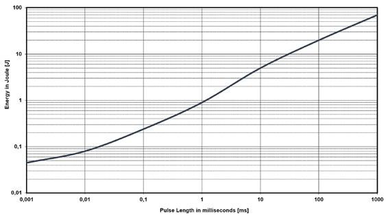
Description of Pulse Energy Curve
Shape of pulse = e-function
Time between two pulses = 1 second
Pulse length = time constant of 1 tau (1 means ... tau = 1ms)
Example At 1 ms tau the MXP 35 with e.g. 1 Ω to 10 Ω can withstand an energy level of about 0.9 J, when the pulse pause time is ≥ 1s
At a symmetrical frequency > 1 kHz at pulse length ≥ 10 μs. the maximum applied pulse energy for MXP 35 is a result out of the nominal power 35 W divided by the operating frequency (at 25°C bottom case) (E = 35 W / F)
Pulse Power Curve (typical rating for MXP 35)
The power curve shows the max. possible power which can be applied for a certain duration. Referring to the same test procedure as described above.
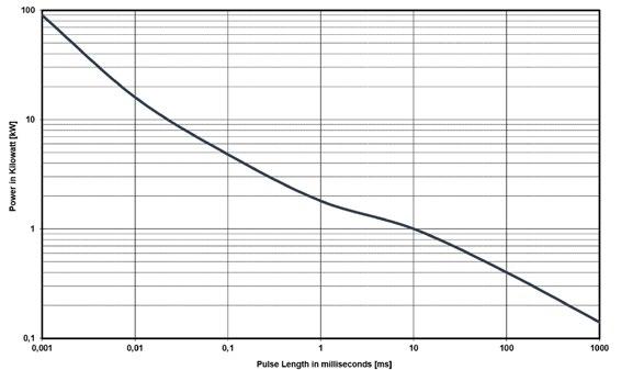
Example
Description of Pulse Power Curve
Shape of pulse = e-function
Time between two pulses = 1 second
Pulse length = time constant of 1 tau (1 means ... tau = 1ms)
For the time-constant of 1 ms you can apply about 1.8 kW max. (Pp = 2*E / τ)à, if the time between two such peaks is ≥ 1s
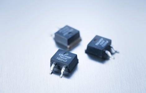
Series MSP 35 SMD TO-220
(MHP 35 for high temperature soldering)
35 W Thick Film Resistor for surface mount including Metal Tab 1/2
35 W Film Power Resistor for surface mount including metal tab.
Features
35 W operating power
SMD TO-220 package configuration
Molded case for environmental protection
Resistor element is electrically insulated from the metal sink tab
Non-Inductive design
ROHS compliant
Materials in accordance with UL 94 V-0
High soldering version available
Technical Specifications
Resistance value 0.1 Ω to 1 MΩ (other values on special request)
Resistance tolerance ±1 % to ± 10 %
Temperature coefficient
±0.5 % on special request for limited ohmic values
< 3 Ω: ask for details
≥ 3 Ω to 10 Ω: ±100 ppm + 0.002 Ω/°C ≥ 10 Ω: ±50 ppm/°C (referenced to 25 °C, ΔR taken at +85°C)
Power rating 35 W at 25°C bottom case temperature
Maximum operating voltage 350 V
Dielectric strength voltage 1800 V AC
Insulation resistance > 10 GΩ at 1000 V DC
Momentary overload 2x rated power with applied voltage not to exceed 1.5x maximum continuous operating voltage for 5 s. ΔR ±(0.3 % + 0.01 Ω) max.
Load life
Moisture resistance
Thermal shock
MIL -R-39009, 2000 h at rated power, ΔR ±(1.0 % + 0.01 Ω) max.
MIL -STD-202, method 106 ΔR = (0.5 % + 0.01 Ω) max.
MIL -STD-202, method 107, Cond. F, ΔR = (0.3 % + 0.01 Ω) max.
Working temperature range -55 °C to +175 °C
Terminal strength
Vibration, high frequency
MIL -STD-202, method 211, Cond. A (Pull Test) 2.4 N, ΔR = (0.2 % + 0.01 Ω) max.
MIL -STD-202, method 204, Cond. D, ΔR = (0.2 % + 0.01 Ω) max.
Lead material nickel-plated copper, dip-tinned
Ground plate material german silver; alternative material on request
Heat resistance to cooling plate Rth < 4.28 K/W
Weight ~1,4 g
Dimensions in mm
Tolerances ±0.2 unless otherwise noted! TO-220 style power package for SMD applcations 35 W power rating at 25°C case temerature. Flatness of ground plate to contacts <0.1mm
Derating (thermal resist.) MSP-35: 0.23 W/K (4.28 K/W)
Case temperature must be used for definition of the applied power limit. Case temperature measurement must be done with a thermocouple contacting the center of the component mounted on the designed heat sink. Thermal grease should be applied properly.
How to make a request
MSP_Ohmic Value_Tolerance
For example: MSP 39R 5%
Example for higher solder profile: MHP 560R 1%
Soldering Note:
During surface mount soldering, the soldering temp. profile must not cause the metal tab of this device to exceed 215°C
For solder profile temp. above 215°C up to max. 260°C, please use our alternative type MHP 35 SMD TO-220
Soldering Template
Series MSP 35 SMD TO-220
Pulse Energy Curve (typical rating for MSP 35)
Note: These energy values are reference values → depending on ohmic value e.g. 1 Ω to 10 Ω and used resistive paste, a variation in max. energy load capability is possible
Test procedure
Every test resistor was mounted with thermal compound (0.9 W/mK) on a water cooled heatsink
Constant inlet water temperature: +50°C
The test time of each tested resistor: 10min.
Break time between two pulses: 1s.
To determine good / defect parts the ohmic value was measured before and after tests: a change of tolerance of more than 0.1% means defect
Example
Description of Pulse Energy Curve
Shape of pulse = e-function
Time between two pulses = 1 second
Pulse length = time constant of 1 tau (1 means ... tau = 1ms)
At 1 ms tau the MXP 35 with e.g. 1 Ω to 10 Ω can withstand an energy level of about 0.9 J, when the pulse pause time is ≥ 1s
At a symmetrical frequency > 1 kHz at pulse length ≥ 10 μs. the maximum applied pulse energy for MXP 35 is a result out of the nominal power 35 W divided by the operating frequency (at 25°C bottom case) (E = 35 W / F)
Pulse Power Curve (typical rating for MSP 35)
The power curve shows the max. possible power which can be applied for a certain duration. Referring to the same test procedure as described above.
Example
Description of Pulse Power Curve
Shape of pulse = e-function
Time between two pulses = 1 second
Pulse length = time constant of 1 tau (1 means ... tau = 1ms)
For the time-constant of 1 ms you can apply about 1.8 kW max. (Pp = 2*E / τ)à, if the time between two such peaks is ≥ 1s
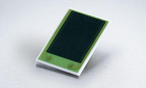
Series SC-55
AECQ200 ready
PCB soldered power resistors ideal for high frequency pulsed applications, snubber, gate control, bleeder, filter, rush current protection, PV, UPS, motor control inverters and passive discharge.
Features
Low profile SMD surge capable thick film resistor
Low thermal resistance offers excellent pulse energy performance
Small size TO-263 footprint with power density
Perfectly suited for automotive applications with a temperature range from -55 °C to +175 °C
Technical Specifications
Resistance value 500 mΩ to 5 kΩ (max. 1 MΩ upon request) (measured at +25 °C ± 3 °C)
Resistance tolerance ±0.5 % to ±10 % (other values on special request) (measured at +25 °C ± 3 °C)
Temperature coefficient <2 Ω: 2 Ω to 10 Ω: >10 Ω: ±500 ppm/°C ±250 ppm/°C ±100 ppm/°C
Rated power 55 W at <25 °C at bottom ceramic
Operating temperature -55 °C to +175 °C
Heat resistance <3.0 K/W resistor to bottom solder pad
Maximum operating voltage 900 V (not exceeding max. power)
Maximum operating current 10 A
Withstanding voltage 1500 V AC (method: terminal and heat sink, 60 s. 1 mA)
Capacitance 13 pF, typical @ 10 kHz
Inductance 50 nH, typical @ 10 kHz
Load life ±1 % (method: 25 °C, 90 min. ON, 30 min. OFF, 1000 h)
Humidity ±1 % (method: 85 °C, 85 % RH, DC 0.25 W, 1000 h)
Temp. cycle ±0.5 % (method: -55 °C, 30 min.,+125 °C, 30 min., 1000 cycle)
Solder heat ±0.1 % (method: 260 °C ± 5 °C, 10 ± 1 s.)
Lead solderability over 95 % of surface (250 ° ± 5 °C, 3 s.)
Insulation resistance over 1000 MΩ (between terminals and heat sink)
Vibration ±0.25 % (MIL-STD-202, Method 204)
Transport conditions 15-60 % rel. humidity (12 weeks -30 °C to +90 °C)
Storage conditions 15-60 % rel. humidity (-30 °C to +70 °C)
Weight <0.4 g
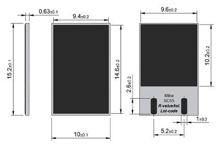
Dimensions in mm
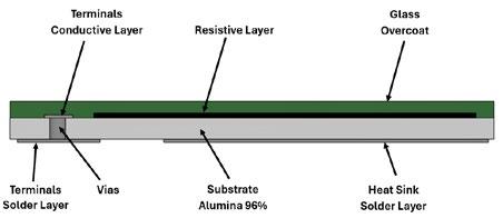
Construction
How to make a request
SC-55_Ohmic Value_Tolerance
For example: SC-55 90R 5%
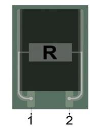
Circuit diagram
Series SC-55
Derating Temperature Rise*
* Actual temperature rise for SC-55 that is jointed on a metal insulated circuit board of 50 mm x70 mm x 1 mm thick. Temperature values recorded after 5 min. of continuous power.
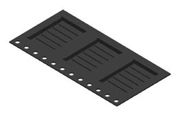
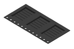
Tape and Reel Measurements
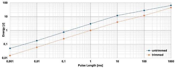
** Pulse energy durability tests has been performed with 10 Ω resistors; a variation in max. energy load capability is possible and depends on ohmic value, resistive paste, trimming percentage and testing conditions.
Series AXP-50
50 W Power Resistor with four wire terminals 1/1
The new design with its non-inductive thick film Metal Oxide Technology prevents potential problems with clearance and creeping distance from terminal to base plate by means of flexible connecting leads.
This unique design allows you to use this elements in the following areas: variable speed drives, power supplies, control devices, telecommunications, robotics, motor controls and other switching devices.
Features
1x 50 W / 2x 20 W / 3x 10 W operating power
Non-Inductive design
ROHS compliant
Materials in accordance with UL 94 V-0
Technical Specifications
Resistance value 1 Ω to 1 MΩ
Resistance tolerance ±1 % to ±10 %
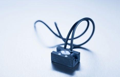
Temperature coefficient ±50 ppm/°C to ±250 ppm/°C (at +85°C ref. to + 25°C)
Power rating up to 50 W at 85°C bottom case temperature (see configurations)
Operating working voltage 500 V up to 1000 V = "S"-version up to 1000 V + higher pulse capability = "U"-version
Dielectric strength 5 kV DC (3 kV AC, higher values on special request) between terminal and case
Internal electric strength between R1 & R2 5 kV DC
Isolation voltage between R1 & R2
500 V (higher on special request)
Working temperatur range -55°C to +155°C
Mounting - torque 1.0 Nm to 1.2 Nm
Standard cable length 100 mm (other lengths on special request)
Standard cable type 4GKW, 0,5 mm2, black Weight ~22 g
Suggested Mounting Procedure:
1.) Position component and press down by hand
2.) Fix both mounting screws (M3) with 0.1 to 0.2 Nm torque
3.) Apply final torque to mounting screws of 1.0 to 1.2 Nm
Dimensions in mm [inches]
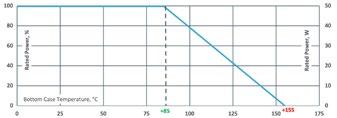
Derating (thermal resist.) AXP-50: 0.995 W/K (1.005 K/W) (for conf. 1, 2 and 3)
Best results can be reached by using a thermal transfer compound with a heat conductivity of at least 1 W/mK. The flatness of the cooling plate must be better than 0.05 mm overall. Surface roughness should not exceed 6.4 μm.
How to make a request
AXP-50-Configuration_Ohmic Value_ Tolerance
For example: AXP-50-1 1K 10% or AXP-50-4 2x50R 5%
Exampe for higher working voltage: AXP-50-1-S 55K 5%
"S"-version: special trimming process "U"-version: untrimmed
Configurations
Series AXP-100 B
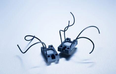
The new design with its non-inductive thick film Metal Oxide Technology prevents potential problems with clearance and creeping distance from terminal to base plate by means of flexible connecting leads.
This unique design allows you to use this elements in the following areas: variable speed drives, power supplies, control devices, telecommunications, robotics, motor controls and other switching devices.
Features
1x 100 W / 2x 38 W / 3x 17 W operating power
Non-Inductive design
ROHS compliant
Materials in accordance with UL 94 V-0
Technical Specifications
Resistance value 1 Ω to 1 MΩ
Resistance tolerance ±1 % to ±10 %
Temperature coefficient ±50 ppm/°C to ±250 ppm/°C (at +85°C ref. to + 25°C)
Power rating up to 100 W at 85°C bottom case temperature (see configurations)
Operating working voltage 500 V up to 1500 V = "S"-version up to 1500 V + higher pulse capability = "U"-version
Short time overload 1,5x rated power for 10 s, ΔR = 0.4% max. (for conf. 1, 2 and 3)
Dielectric strength 5 kV DC (3 kV AC, higher values on special request) between terminal and case
Internal electric strength between R1 & R2 5 kV DC
Working temperatur range -55°C to +155°C
Mounting - torque 1.0 Nm to 1.2 Nm
Standard cable length 100 mm (other lengths on special request)
Standard cable type PVC 0,75 mm2, 20-AWG black Weight ~22 g
Suggested Mounting Procedure:
1.) Position component and press down by hand
2.) Fix both mounting screws (M4) with 0.1 to 0.2 Nm torque
3.) Apply final torque to mounting screws of 1.0 to 1.2 Nm
Dimensions in mm [inches]
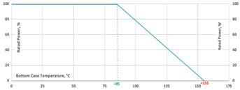
Derating (thermal resist.) AXP-100 B: 1.42 W/K (0.70 K/W) (for conf. 1, 2 and 3)
Best results can be reached by using a thermal transfer compound with a heat conductivity of at least 1 W/mK. The flatness of the cooling plate must be better than 0.05 mm overall. Surface roughness should not exceed 6.4 μm.
How to make a request
AXP-Configuration B_Ohmic Value_ Tolerance
For example: AXP-1 B 2K 10% or AXP-4 B 2x50R 5%
Example for higher working voltage: AXP-1-B-S 55K 5%
"S"-version: special trimming process "U"-version: untrimmed
Configurations (P / package)
100 W Power Resistor with four wire terminals, version B for enforced mechanical stability 1/1 Boreholes distance from min. 30.0 mm to max. 37.0 mm
Power Resistors
Series AXP-150
150 W Plane Non-Inductive Power Resistor
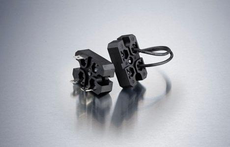
Features
1x150 W / 2x60 W / 3x33 W operating power
SOT-227 mould package
Two different terminal options available
Good mechanical reliability
Non-Inductive design
Technical Specifications
Resistance value 0.5 Ω to 1 MΩ
Resistance tolerance ±1 % to ±10 %
Temperature coefficient ±50 ppm/°C to ±250 ppm/°C (+25°C to +105°C, ref. to +25°C)
Power rating 150 W at 70°C bottom case temperature (see configurations)
Maximum operating voltage 500 V DC up to 1500 V = "S"-version up to 1500 V + higher pulse capability = "U"-version on special request
Capacitance (mass) 36 pF
Capacitance (parallel) 12 pF
Inductance ≤ 50 nH
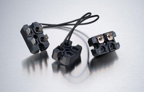
Electric clearance / creepage distance 2 terminal types available (see below)
Load life 1000 h at rated power, BCT at 70°C, ΔR ≤ ±(1.0%R + 0.001Ω)
Moisture resistance 56 days / 40°C RH ≥ 95% ΔR ≤ ±(0.25%R + 0.001Ω)
Thermal schock -40°C to +125°C, 5 times, ΔR ≤ ±(0.25%R + 0.001Ω)
Vibration, high frequency MIL-Std.-202, method 204, Cond. D ΔR ≤ ±(0.2%R + 0.001Ω)
Dielectric strength 5 kV DC, 3 kV AC (higher on special request)
Base plate installation M4 screw, max. torque 1.3 Nm
Operating temperature range -55 °C to +155 °C Weight ~18 g
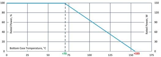
Derating (thermal resist.) AXP-150: 1.76 W/K (0.57 K/W)
Without a heat sink, when in open air at 25°C, the AXP-150 is rated for 3.5 W.
How to make a request
AXP-150-Configuration_Terminal Type_ Ohmic Value_Tolerance
For example: AXP-150-2-C 50R 5%
"S"-version: special trimming process "U"-version: untrimmed
Configurations (P / package)
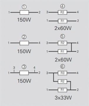
Version 5: ohmic value between contact 2 and 4 aprox. 3mΩ
Series AXP-150
Terminal B dimensions in mm [inches]
Terminal (#1 ~ #4) linear distance:
#1 to #2#3 to #4 ≥7 mm
#1 to #3#2 to #4 ≥19 mm
#1 to #4#2 to #3 ≥20 mm
Terminal to board ≥11 mm
When using “insertion type terminal“ the distance reduced by 1 mm
Terminal (#1 ~ #4) creep distance:
#1 to #2#3 to #4 ≥10 mm
#1 to #3#2 to #4 ≥23 mm
#1 to #4#2 to #3 ≥26 mm
Terminal to board ≥13 mm
When using “insertion type terminal“ the distance reduced by 1 mm
Terminal C dimensions
Series AXS-600 / AXF-600 / AXP-600
600 W Power Resistor at 125°C bottom case, different terminal options available
Due to our Non-Inductive design,the AXS, AXF, AXP series is ideally suited for high-frequency and pulse-loading applications. Through direct mounting on a heat sink, significant cost advantage can be realized. Main applications are: variable speed drives, power supplies, control devices, telecommunications, robotics, motor controls and other switching devices.
Features
Multiple resistors in 1 package
Different terminal options available
Non-Inductive design
ROHS compliant
Materials in accordance with UL 94 V-0
General pulse load information (ask for details)
T hermal interface management available (ask for details)
Technical Specifications
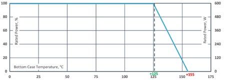
How to make a request
Resistance value 0.15 Ω to 5 KΩ (higher values on special request)
Resistance tolerance ±5 % to 10 % (configuration 4,5,6 only tolerance ±10% possible)
Temperature coefficient > 1R: ±250 ppm/°C (at +85°C ref. to +25°C) lower TCR on special request for limited ohmic values
Power rating up to 600 W at 125°C bottom case temperature (see configurations)
Short time overload 1.25x rated power at 85°C bottom case temperature for 10 s., ΔR = 0.4% max. (for conf. 1, 2 and 3)
Operating working voltage up to 1500 V DC (higher on request)
Voltage proof dielectric strength up to 4,000 V DC against ground
Insulation resistance > 10 GΩ at 1000 V DC
Isolation voltage betweeen R1 & R2 & R3 500 V DC (1000 V DC on special request)
Protection class acc. to IEC 950/CSA22.2 950/M-89 and EN 60950.88:2
Heat resistance to cooling plate Rth ≤ 0.083 K/W
Capacitance/mass 25 pF (typical), measuring frequency 10 kHz (depending on type/connection option, ask for details)
Serial inductivity 50 nH (typical), measuring frequency 10 kHz (depending on type/connection option, ask for details)
Working temperature range -55°C to +155°C
Mounting - torque for base plate (static) 1.3 Nm to 1.5 Nm M4 screws
Mounting - torque for contacts (static) 1.1 Nm to 1.3 Nm M4 screws, screw-in depth max. 5mm
Standard cable length (AXP-600) 100 mm (other lengths on special request)
Standard cable type (AXP-600) 4GKW-AX 1800V Weight ~16 g
AXS-600-Configuration_Ohmic Value_ Tolerance
AXF-600-Configuration_Ohmic Value_ Tolerance
AXP-600-Configuration_Ohmic Value_ Tolerance
For example: AXS-600 27R 10% or AXP-600 2x220R 5%
Configurations (P / package) Version 5: ohmic value between contact 2 and 4 aprox. 3mΩ
Derating (thermal resist.) AXS-600: 12.05 W/K (≤ 0.083 K/W) (for conf. 1, 2 and 3)
Best results can be reached by using a thermal transfer compound with a heat conductivity of at least 2.9 W/mK. The flatness of the cooling plate must be better than 0.05 mm overall. Surface roughness should not exceed 6.4 µm.
auchKatalogzeichnungeninAXP-150
AXS-600 (screw connection) dimensions in
(fast-on connection) dimensions in mm [inches]
Katalogzeichnung
AXP-600 dimensions in mm [inches] (Terminal standard length = 100mm, others on special request)
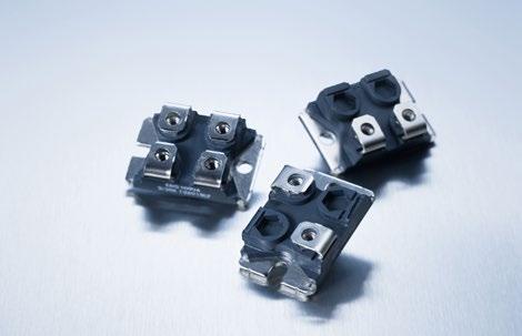
Series GXP 120, SOT-227
AECQ200 ready
Due to our Non-Inductive design, the GXP series is ideally suited for high-frequency and pulse-loading applications. Through direct mounting on a heat sink, significant cost advantage can be realized. Main applications are: variable speed drives, power supplies, control devices, telecommunications, robotics, motor controls and other switching devices.
Features
multiple resistors in 1 package
Non-Inductive design
ROHS compliant
Materials in accordance with UL 94 V-0
Resistor is also available with UL certification (ask for details)
T hermal interface management available (ask for details)
Technical Specifications
Resistance value 0.1 Ω to 1 MΩ
Resistance tolerance ±1 % to ± 10 %
Temperature coefficient > 1R: ±250 ppm/°C (at +85°C ref. to +25°C) lower TCR on special request for limited ohmic values
Power rating up to 120 W at 85°C bottom case temperature (see configurations)
Short time overload
Operating working voltage
1.5x rated power at 85°C bottom case temperature for 10 s., ΔR = 0.4% max. (for conf. 1, 2 and 3)
500 V up to 1500 V = "S"-version up to 1500 V + higher pulse capability = "U"-version
Partial discharge up to 2000 Vrms / 80pC
Tests only on special request
Voltage proof dielectric strength up to 4000 V DC against ground
Insulation resistance > 10 GΩ at 1000 V DC
Isolation voltage betweeen R1 & R2
500 V DC (1000 V DC on special request)
Protection class acc. to IEC 950/CSA22.2 950/M-89 and EN 60950.88:2
Comparative Tracking Index (CTI)
standard > 200 V (> 600 V on special request = "H"-version)
Heat resistance to cooling plate Rth < 0.45 K/W
Capacitance/mass 45 pF (typical), measuring frequency 10 kHz
Serial inductivity GXP-1 typical 40 nH, measuring frequency 10 kHz
Working temperature range -55°C to +155°C
Mounting - torque for base plate (static) 1.3 Nm to 1.5 Nm M4 screws
Mounting - torque for contacts (static) 1.1 Nm to 1.3 Nm M4 screws, screw-in depth max. 5 mm
Weight ~26 g
Dimensions in mm [inches]
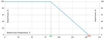
Derating (thermal resist.) GXP-120: 2.22 W/K (0.45 K/W) (for conf. 1, 2 and 3)
Best results can be reached by using a thermal transfer compound with a heat conductivity of at least 1 W/mK. The flatness of the cooling plate must be better than 0.05 mm overall. Surface roughness should not exceed 6.4 μm.
How to make a request
GXP-Configuration_Ohmic Value_Tolerance
For example: GXP-1 1R 10% or GXP-4 2x50K 5%
Example for higher working voltage or CTI GXP-4-S 2x40R 10% or GXPH-2 40K 10%
"S"-version: special trimming process "U"-version: untrimmed "H"-version: type with CTI >600
Configurations (P / package)
120 W Power Resistor in the "ISOTOP" power device 1/2 8
Series GXP 120, SOT-227
AECQ200 ready
Pulse Energy Curve (typical rating for GXP 120)
Note: These energy values are reference values depending on ohmic value e.g. 1 Ω to 10 Ω and used resistive paste, a variation in max. energy load capability is possible
Test procedure
Every test resistor was mounted with thermal compound (0.9 W/mK) on a water cooled heatsink
Constant inlet water temperature: +50°C
The test time of each tested resistor: 10min.
Break time between two pulses: 1s.
To determine good / defect parts the ohmic value was measured before and after tests: a change of tolerance of more than 0.1% means defect
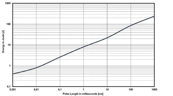
Example
Description of Pulse Energy Curve
Shape of pulse = e-function
Time between two pulses = 1 second
Pulse length = time constant of 1 tau (1 means ... tau = 1ms)
At 1 ms tau the GXP 120 with e.g. 1 Ω to 10 Ω can withstand an energy level of about 8 J, when the pulse pause time is ≥ 1s
At a symmetrical frequency > 1 kHz at pulse length ≥ 10 μs. the maximum applied pulse energy for GXP 120 is a result out of the nominal power 120 W divided by the operating frequency (at 85°C bottom case) (E = 120 W / F)
Pulse Power Curve (typical rating for GXP 120)
The power curve shows the max. possible power which can be applied for a certain duration. Referring to the same test procedure as described above.
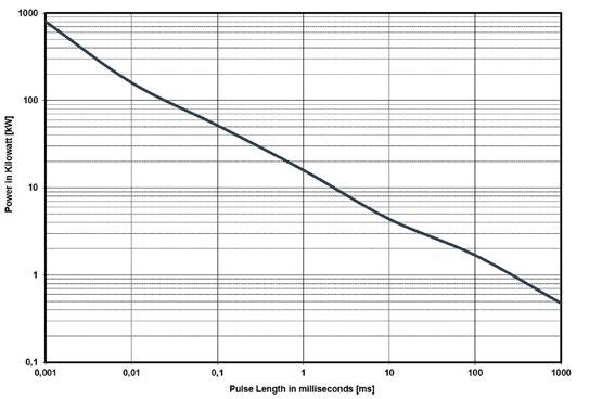
Example
Description of Pulse Power Curve
Shape of pulse = e-function
Time between two pulses = 1 second
Pulse length = time constant of 1 tau (1 means ... tau = 1ms)
For the time-constant of 1 ms you can apply about 16 kW max. (Pp = 2*E / τ)à, if the time between two such peaks is ≥ 1s
Power Resistors
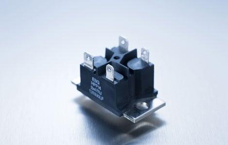
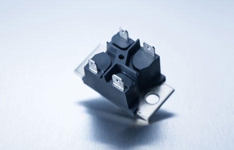
Series HPP 150
Miba Resistors HPP series is rated at 150 W mounted to a heat sink. The increased height of the package makes the resistor ideal in applications where creeping distance must meet the VDE 0160 and UL 94 V-0 standards.
Features
multiple resistors in 1 package
Easy mounting using already existing infrastructure
Non-Inductive design
ROHS compliant
Materials in accordance with UL 94 V-0 and VDE 0160
Resistor is also available with UL certification (ask for details)
T hermal interface management available (ask for details)
Technical Specifications
Resistance value 1 Ω to 1 MΩ (other values on special request)
Resistance tolerance ±1 % to ±10 %
Temperature coefficient ±250 ppm/°C (at +85°C ref. to + 25°C) lower TCR on special request for limited ohmic values
Power rating up to 150 W at 85°C bottom case temperature (see configurations)
Operating working voltage 500 V up to 1500 V = "S"-version up to 1500 V + higher pulse capability = "U"-version
Voltage proof 5000 V DC, 3000 V AC
Insulations resistance > 10 GΩ at 1000 V DC
Insolation voltage between R1 & R2 500 V DC (1000 V DC on special request)
Comparative Tracking Index (CTI) standard > 200 V (> 600 V on special request = "H"-version)
Heat resistance to cooling plate Rth < 0.47 K/W
Capacitance/mass 45 pF (typical), measuring frequency 10 kHz
Working temperatur range -55°C to +155°C
Mounting - torque for base plate (static) 1.3 Nm to 1.5 Nm M5 screws Weight ~38 g
Air distance contact to contact:
Contacts 1 and 2 resp. 3 and 4
- without fast-on-Plug: 9.2 mm
- with fast-on-Plug: 8.2 mm
Contacts 1 and 4 resp. 2 and 3
- without fast-on-Plug: 21.9 mm
- with fast-on-Plug: 20.9 mm
Contacts 2 resp. 3 and M5
- mounting screw with washer
- without fast-on-Plug: 16.3 mm
- with fast-on-Plug: 15.9 mm
Contacts 1 resp. 4 and M5
- mounting screw with washer
- without fast-on-Plug: 15.5 mm
- with fast-on-Plug: 15.0 mm
Dimensions in mm [inches]
Creeping distance:
Contacts 1 and 2 resp. 3 and 4
- without fast-on-Plug: 20.2 mm
- with fast-on-Plug: 19.0 mm
Contacts 1 and 4 resp. 2 and 3
- without fast-on-Plug: 27.4 mm
- with fast-on-Plug: 25.8 mm
Contacts 2 resp. 3 to base plate
- without fast-on-Plug: 20.2 mm
- with fast-on-Plug: 19.8 mm
Contacts 1 resp. 4 to base plate
- without fast-on-Plug: 19.5 mm
- with fast-on-Plug: 18.9 mm
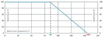
Derating (thermal resist.) HPP-150: 2.14 W/K (0.47 K/W) (for conf. 3)
Best results can be reached by using a thermal transfer compound with a heat conductivity of at least 1 W/mK. The flatness of the cooling plate must be better than 0.05 mm overall. Surface roughness should not exceed 6.4 μm.
How to make a request
HPP-Configuration_Ohmic Value_Tolerance
For example: HPP-5 2x2R 10% or HPP-6 3x8K 5%
Example for higher working voltage: HPP-4-S 2x10R 5%
"S"-version: special trimming process "U"-version: untrimmed "H"-version: type with CTI >600
Configurations (P / package)
Series HPP 150
Pulse Energy Curve (typical rating for HPP 150)
Note: These energy values are reference values → depending on ohmic value e.g. 1 Ω to 10 Ω and used resistive paste, a variation in max. energy load capability is possible
Test procedure
Every test resistor was mounted with thermal compound (0.9 W/mK) on a water cooled heatsink
Constant inlet water temperature: +50°C
The test time of each tested resistor: 10min.
Break time between two pulses: 1s.
To determine good / defect parts the ohmic value was measured before and after tests: a change of tolerance of more than 0.1% means defect
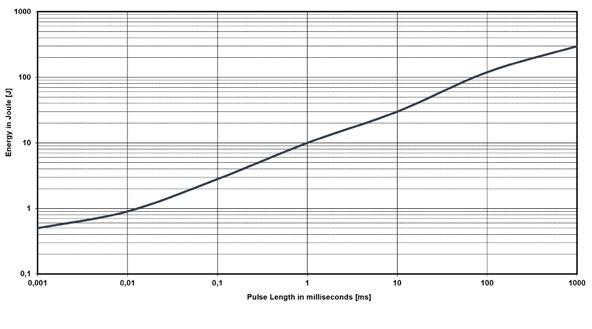
Description of Pulse Energy Curve
Shape of pulse = e-function
Time between two pulses = 1 second
Pulse length = time constant of 1 tau (1 means ... tau = 1ms)
Example
At 1 ms tau the HPP 150 with e.g. 1 Ω to 10 Ω can withstand an energy level of about 10 J, when the pulse pause time is ≥ 1s
At a symmetrical frequency > 1 kHz at pulse length ≥ 10 μs. the maximum applied pulse energy for HPP 150 is a result out of the nominal power 150 W divided by the operating frequency (at 85°C bottom case) (E = 150 W / F)
Pulse Power Curve (typical rating for HPP 150)
The power curve shows the max. possible power which can be applied for a certain duration. Referring to the same test procedure as described above.

Example
Description of Pulse Power Curve
Shape of pulse = e-function
Time between two pulses = 1 second
Pulse length = time constant of 1 tau (1 means ... tau = 1ms)
For the time-constant of 1 ms you can apply about 20 kW max. (Pp = 2*E / τ)à, if the time between two such peaks is ≥ 1s
Series VHP
180 W Power Resistor according to VDE 0160 und UL 94 V-0
Miba Resistors VHP series is rated at 180 W mounted to a heat sink. The increased height of the package makes the resistor ideal in applications where creeping distance must meet the VDE 0160 and UL 94 V-0 standards.
Features
multiple resistors in 1 package
Easy mounting using already existing infrastructure
Non-Inductive design
ROHS compliant
Materials in accordance with UL 94 V-0 and VDE 0160
Resistor is also available with UL certification (ask for details)
T hermal interface management available (ask for details)
Technical Specifications
Resistance value 1 Ω to 1 MΩ (higher values on special request)
Resistance tolerance ±1 % to ±10 %
Temperature coefficient ±250 ppm/°C (at +85°C ref. to + 25°C) lower TCR on special request for limited ohmic values
Power rating up to 180 W at 85°C bottom case temperature (see configurations)
Operating working voltage
500 V up to 1500 V = "S"-version up to 1500 V + higher pulse capability = "U"-version
Voltage proof 5000 V DC, 3000 V AC
Insulations resistance > 10 GΩ at 1000 V DC
Insolation voltage between R1 & R2 500 V DC (1000 V DC on special request)
Comparative Tracking Index (CTI) standard > 200 V (> 600 V on special request = "H"-version)
Heat resistance to cooling plate Rth < 0.40 K/W
Capacitance/mass 45 pF (typical), measuring frequency 10 kHz
Working temperatur range -55°C to +155°C
Mounting - torque for base plate (static) 1.3 Nm to 1.5 Nm M5 screws
Weight ~38 g
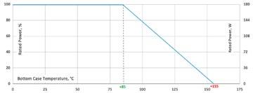
Derating (thermal resist.) VHP: 2.5 W/K (0.40 K/W) (for conf. 3)
Best results can be reached by using a thermal transfer compound with a heat conductivity of at least 1 W/mK. The flatness of the cooling plate must be better than 0.05 mm overall. Surface roughness should not exceed 6.4 μm.
How to make a request
VHP-Configuration_Ohmic Value_Tolerance
Air distance contact to contact:
Contacts 1 and 2 resp. 3 and 4
- without fast-on-Plug: 9.2 mm
- with fast-on-Plug: 8.2 mm
Contacts 1 and 4 resp. 2 and 3
- without fast-on-Plug: 21.9 mm
- with fast-on-Plug: 20.9 mm
Contacts 2 resp. 3 and M5
- mounting screw with washer
- without fast-on-Plug: 16.3 mm
- with fast-on-Plug: 15.9 mm
Contacts 1 resp. 4 and M5
- mounting screw with washer
- without fast-on-Plug: 15.5 mm
- with fast-on-Plug: 15.0 mm
Dimensions in mm [inches]
Creeping distance:
Contacts 1 and 2 resp. 3 and 4
- without fast-on-Plug: 20.2 mm
- with fast-on-Plug: 19.0 mm
Contacts 1 and 4 resp. 2 and 3
- without fast-on-Plug: 27.4 mm
- with fast-on-Plug: 25.8 mm
Contacts 2 resp. 3 to base plate
- without fast-on-Plug: 20.2 mm
- with fast-on-Plug: 19.8 mm
Contacts 1 resp. 4 to base plate
- without fast-on-Plug: 19.5 mm
- with fast-on-Plug: 18.9 mm
For example: VHP-5 2x2R 10% or VHP-6 3x8K 5%
Example for higher working voltage: VHP-5-S 10R 5%
"S"-version: special trimming process "U"-version: untrimmed "H"-version: type with CTI >600
Configurations (P / package)
Series VHP
Pulse Energy Curve (typical rating for VHP)
Note: These energy values are reference values → depending on ohmic value e.g. 1 Ω to 10 Ω and used resistive paste, a variation in max. energy load capability is possible
Test procedure
Every test resistor was mounted with thermal compound (0.9 W/mK) on a water cooled heatsink
Constant inlet water temperature: +50°C
The test time of each tested resistor: 10min.
Break time between two pulses: 1s.
To determine good / defect parts the ohmic value was measured before and after tests: a change of tolerance of more than 0.1% means defect
Description of Pulse Energy Curve
Shape of pulse = e-function
Time between two pulses = 1 second
Pulse length = time constant of 1 tau (1 means ... tau = 1ms)
Example
At 1 ms tau the VHP with e.g. 1 Ω to 10 Ω can withstand an energy level of about 10 J, when the pulse pause time is ≥ 1s
At a symmetrical frequency > 1 kHz at pulse length ≥ 10 μs. the maximum applied pulse energy for VHP is a result out of the nominal power 180 W divided by the operating frequency (at 85°C bottom case) (E = 180 W / F)
Pulse Power Curve (typical rating for VHP)
The power curve shows the max. possible power which can be applied for a certain duration. Referring to the same test procedure as described above.
Example
Description of Pulse Power Curve
Shape of pulse = e-function
Time between two pulses = 1 second
Pulse length = time constant of 1 tau (1 means ... tau = 1ms)
For the time-constant of 1 ms you can apply about 20 kW max. (Pp = 2*E / τ)à, if the time between two such peaks is ≥ 1s
Series HPS 150
150 W Power Resistor – only configuration 2 possible
Miba Resistors HPS series is rated at 150 W mounted to a heat sink. The increased height of the package makes this resistor ideal in applications where creeping distance must meet the VDE 0160 and UL 94 V-0 standards. Main applications are: motor drives & controls, medical, frequency converters and instrumentation.
Features
150 W operating power
Easy mounting using already existing infrastructure
Non-Inductive design
ROHS compliant
Materials in accordance with UL 94 V-0 and VDE 0160
Resistor is also available with UL certification (ask for details)
T hermal interface management available (ask for details)
Technical Specifications
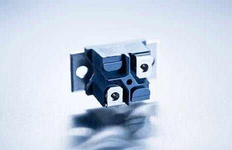
Resistance value 1 Ω to 1 MΩ (other values on special request)
Resistance tolerance ±1 % to ±10 %
Temperature coefficient ±250 ppm/°C (at +85°C ref. to + 25°C) lower TCR on special request for limited ohmic values
Power rating 150 W at 85°C bottom case temperature
Operating working voltage 500 V up to 1500 V = "S"-version up to 1500 V + higher pulse capability = "U"-version
Voltage proof 5000 V DC, 3000 V AC
Insulations resistance > 10 GΩ at 1000 V DC
Comparative Tracking Index (CTI) standard > 200 V (> 600 V on special request = "H"-version)
Heat resistance to cooling plate Rth < 0.47 K/W
Capacitance/mass 45pF (typical), measuring frequency 10 kHz
Working temperatur range -55°C to +155°C
Mounting - torque for base plate (static) 1.3 Nm to 1.5 Nm M5 screws
Mounting - torque for contacts (static) 1.1 Nm to 1.5 Nm M4 screws, screw-in depth max. 5 mm Weight ~38 g
Air distance contact to contact:
Contact to contact > 9.2 mm
Contact to base plate > 13.2 mm (with mounting screw M5 and washer)
Dimensions in mm [inches]
Creeping distance:
Contact to base plate 17.0 mm
Contact to contact - without PT-screw > 22.8 mm - with PT-screw > 20.2 mm
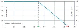
Derating (thermal resist.) HPS-150: 2.14 W/K (0.47 K/W)
Best results can be reached by using a thermal transfer compound with a heat conductivity of at least 1 W/mK. The flatness of the cooling plate must be better than 0.05 mm overall. Surface roughness should not exceed 6.4 μm.
How to make a request HPS-2_Ohmic Value_Tolerance
For example: HPS-2 1R 10%
Example for higher working voltage: HPS-2-S 40K 2%
"S"-version: special trimming process "U"-version: untrimmed "H"-version: type with CTI >600
Configuration
2
Only configuration 1 possible
only 1 configuration possible
Series HPS 150
Pulse Energy Curve (typical rating for HPS 150)
Note: These energy values are reference values → depending on ohmic value e.g. 1 Ω to 10 Ω and used resistive paste, a variation in max. energy load capability is possible
Test procedure
Every test resistor was mounted with thermal compound (0.9 W/mK) on a water cooled heatsink
Constant inlet water temperature: +50°C
The test time of each tested resistor: 10min.
Break time between two pulses: 1s.
To determine good / defect parts the ohmic value was measured before and after tests: a change of tolerance of more than 0.1% means defect
Description of Pulse Energy Curve
Shape of pulse = e-function
Time between two pulses = 1 second
Pulse length = time constant of 1 tau (1 means ... tau = 1ms)
Example
At 1 ms tau the HPS 150 with e.g. 1 Ω to 10 Ω can withstand an energy level of about 10 J, when the pulse pause time is ≥ 1s
At a symmetrical frequency > 1 kHz at pulse length ≥ 10 μs. the maximum applied pulse energy for HPS 150 is a result out of the nominal power 150 W divided by the operating frequency (at 85°C bottom case) (E = 150 W / F)
Pulse Power Curve (typical rating for HPS 150)
The power curve shows the max. possible power which can be applied for a certain duration. Referring to the same test procedure as described above.
Example
Description of Pulse Power Curve
Shape of pulse = e-function
Time between two pulses = 1 second
Pulse length = time constant of 1 tau (1 means ... tau = 1ms)
For the time-constant of 1 ms you can apply about 20 kW max. (Pp = 2*E / τ)à, if the time between two such peaks is ≥ 1s
Series HXP 200, SOT-227
200 W Power Resistor in the "ISOTOP" power device
Due to our Non-Inductive design, the HXP series is ideally suited for high-frequency and pulse-loading applications. Through direct mounting on a heat sink, significant cost advantage can be realized. Main applications are: variable speed drives, power supplies, control devices, telecommunications, robotics, motor controls and other switching devices.
Features
multiple resistors in 1 package
Non-Inductive design
ROHS compliant
Materials in accordance with UL 94 V-0
Resistor is also available with UL certification (ask for details)
T hermal interface management available (ask for details)
Technical Specifications
Resistance value 0.1 Ω to 1 MΩ
Resistance tolerance ±1 % to ±10 %
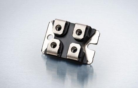
Temperature coefficient > 1R: ±250 ppm/°C (at +85°C ref. to +25°C) lower TCR on special request for limited ohmic values
Power rating up to 200 W at 85°C bottom case temperature (see configurations)
Short time overload 1.25x rated power at 85°C bottom case temperature for 10 s., ΔR = 0.4% max. (for conf. 1, 2 and 3)
Operating working voltage
500 V up to 1500 V = "S"-version up to 1500 V + higher pulse capability = "U"-version
Partial discharge up to 2000 Vrms / 80pC (Tests only on special request)
Voltage proof dielectric strength up to 4000 V DC against ground
Insulation resistance > 10 GΩ at 1000 V DC
Isolation voltage betweeen R1 & R2 & R3
500 V DC (1000 V DC on special request)
Protection class acc. to IEC 950/CSA22.2 950/M-89 and EN 60950.88:2
Comparative Tracking Index (CTI) standard > 200 V (> 600 V on special request = "H"-version)
Heat resistance to cooling plate Rth < 0.35 K/W
Capacitance/mass 45 pF (typical), measuring frequency 10 kHz
Serial inductivity HXP-1 typical 40 nH, measuring frequency 10 kHz
Working temperature range -55°C to +155°C
Mounting - torque for base plate (static) 1.3 Nm to 1.5 Nm M4 screws
Mounting - torque for contacts (static) 1.1 Nm to 1.3 Nm M4 screws, screw-in depth max. 5 mm
~26 g
Dimensions in mm [inches]
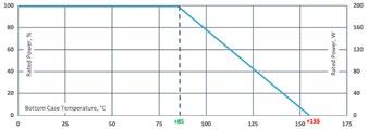
Derating (thermal resist.) HXP-200: 2.86 W/K (0.35 K/W) (for conf. 1, 2 and 3)
Best results can be reached by using a thermal transfer compound with a heat conductivity of at least 1 W/mK. The flatness of the cooling plate must be better than 0.05 mm overall. Surface roughness should not exceed 6.4 μm.
How to make a request
HXP-Configuration_Ohmic Value_Tolerance
For example: HXP-1 1R 10% or HXP-4 2x50K 5%
Example for higher working voltage or CTI HXP-4-S 2x40R 10% or HXPH-2 75K 5%
"S"-version: special trimming process "U"-version: untrimmed "H"-version: type with CTI >600
Series HXP 200, SOT-227
AECQ200 ready
Pulse Energy Curve (typical rating for HXP 200)
Note: These energy values are reference values → depending on ohmic value e.g. 1 Ω to 10 Ω and used resistive paste, a variation in max. energy load capability is possible
Test procedure
Every test resistor was mounted with thermal compound (0.9 W/mK) on a water cooled heatsink
Constant inlet water temperature: +50°C
The test time of each tested resistor: 10min.
Break time between two pulses: 1s.
To determine good / defect parts the ohmic value was measured before and after tests: a change of tolerance of more than 0.1% means defect
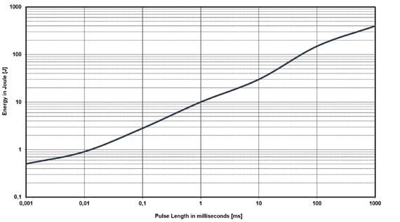
Example
Description of Pulse Energy Curve
Shape of pulse = e-function
Time between two pulses = 1 second
Pulse length = time constant of 1 tau (1 means ... tau = 1ms)
At 1 ms tau the HXP 200 with e.g. 1 Ω to 10 Ω can withstand an energy level of about 10 J, when the pulse pause time is ≥ 1s
At a symmetrical frequency > 1 kHz at pulse length ≥ 10 μs. the maximum applied pulse energy for HXP 200 is a result out of the nominal power 200 W divided by the operating frequency (at 85°C bottom case) (E = 200 W / F)
Pulse Power Curve (typical rating for HXP 200)
The power curve shows the max. possible power which can be applied for a certain duration. Referring to the same test procedure as described above.
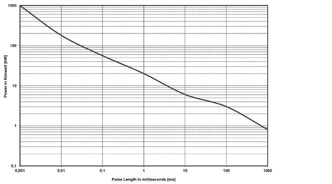
Example
Description of Pulse Power Curve
Shape of pulse = e-function
Time between two pulses = 1 second
Pulse length = time constant of 1 tau (1 means ... tau = 1ms)
For the time-constant of 1 ms you can apply about 20 kW max. (Pp = 2*E / τ)à, if the time between two such peaks is ≥ 1s
Power Resistors
Series HXP-600
600 W Power Resistor at 85°C bottom case
Due to our Non-Inductive design, the HXP series is ideally suited for high-frequency and pulse-loading applications. Through direct mounting on a heat sink, significant cost advantage can be realized. Main applications are: variable speed drives, power supplies, control devices, telecommunications, robotics, motor controls and other switching devices.
Features
multiple resistors in 1 package
Non-Inductive design
ROHS compliant
Materials in accordance with UL 94 V-0
General pulse load information (ask for details)
T hermal interface management available (ask for details)
Technical Specifications
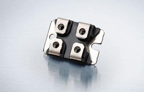
Resistance value 0.15 Ω to 5 KΩ (higher values on special request)
Resistance tolerance ±5 % to 10 % (configuration 4,5,6 only tolerance ±10% possible)
Temperature coefficient depending on ohmic value (ask for details)
Power rating up to 600 W at 85°C bottom case temperature (see configurations)
Short time overload 1.25x rated power at 85°C bottom case temperature for 10 s., ΔR = 0.4% max. (for conf. 1, 2 and 3)
Operating working voltage up to 1500 V
Partial discharge up to 2000 V on 80pC (Tests only on special request)
Voltage proof dielectric strength up to 4000 V DC against ground
Insulation resistance > 10 GΩ at 1000 V DC
Isolation voltage betweeen R1 & R2 & R3 500 V DC (1000 V DC on special request)
Protection class acc. to IEC 950/CSA22.2 950/M-89 and EN 60950.88:2
Comparative Tracking Index (CTI) standard 600 V
Heat resistance to cooling plate Rth < 0.12 K/W
Capacitance/mass 45 pF (typical), measuring frequency 10 kHz
Serial inductivity HXP-1 typical 40 nH, measuring frequency 10 kHz
Working temperature range -55°C to +155°C
Mounting - torque for base plate (static) 1.3 Nm to 1.5 Nm M4 screws
Mounting - torque for contacts (static) 1.1 Nm to 1.3 Nm M4 screws, screw-in depth max. 5mm
Weight ~27 g
Dimensions in mm [inches]
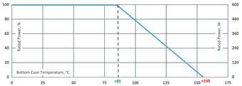
Derating (thermal resist.) HXP-600: 8.33 W/K (0.12 K/W) (for conf. 1, 2 and 3)
How to make a request
HXP-600-Configuration_Ohmic Value_ Tolerance
For example: HXP-600-1 27R 10% or HXP-600-4 2x220R 5%
Best results can be reached by using a thermal transfer compound with a heat conductivity of at least 2.9 W/mK. The flatness of the cooling plate must be better than 0.05 mm overall. Surface roughness should not exceed 6.4 µm. Configurations
Flange Plate Power Resistors
Series PXP 200, SOT-227 (solder pin)
200 W Power Resistor at 85°C Bottom Case 1/2
Miba Resistors general medium power resistor. Main applications are variable speed drives, power supplies, control devices, telecom, robotics, motor controls and other switching designs. Specials and custom designed components on request.
Features
multiple resistors in 1 package
Non-Inductive design
ROHS compliant
Materials in accordance with UL 94 V-0
T hermal interface management available (ask for details)
Technical Specifications
Resistance value 0.1 Ω to 1 MΩ
Resistance tolerance ±1 % to ±10 %
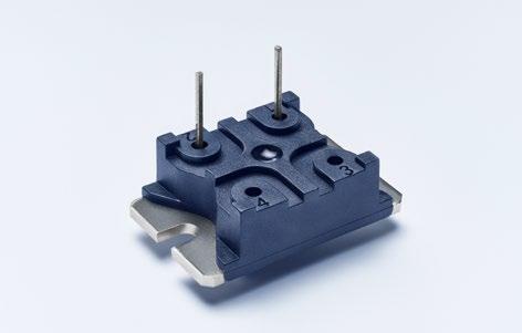
Temperature coefficient > 1R: ±250 ppm/°C (at +85°C ref. to +25°C) lower TCR on special request for limited ohmic values
Power rating up to 200 W at 85°C bottom case temperature (see configurations)
Short time overload
Operating working voltage
1.25x rated power at 85°C bottom case temperature for 10 s., ΔR = 0.4% max. (for conf. 1, 2 and 3)
500 V DC up to 1500 V = "S"-version up to 1500 V + higher pulse capability = "U"-version
Partial discharge up to 2000 Vrms / 80pC (tests only on special request)
Voltage proof dielectric strength up to 4000 V DC against ground
Insulation resistance > 10 GΩ at 1000 V DC
Isolation voltage betweeen R1 & R2 & R3
500 V DC (1000 V DC on special request)
Heat resistance to cooling plate Rth < 0.35 K/W
Capacitance/mass 45 pF (typical), measuring frequency 10 kHz
Serial inductivity PXP-1 typical 40 nH, measuring frequency 10 kHz
Working temperature range -55°C to +155°C
Mounting - torque for base plate (static) 1.3 Nm to 1.5 Nm M4 screws
Weight ~20 g
Dimensions in mm
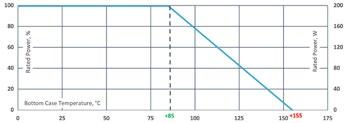
Derating (thermal resist.) PXP-200: 2.86 W/K (0.35 K/W) (for conf. 1, 2 and 3)
Best results can be reached by using a thermal transfer compound with a heat conductivity of at least 1 W/mK. The flatness of the cooling plate must be better than 0.05 mm overall. Surface roughness should not exceed 6.4 μm.
How to make a request
PXP-Configuration_Ohmic Value_Tolerance
For example: PXP-1 4R7 5%
Example for higher working voltage: PXP-1-S 4R7 10%
"S"-version: special trimming process "U"-version: untrimmed
Configurations (P / package)
Series PXP 200, SOT-227 (solder pin)
Pulse Energy Curve (typical rating for PXP 200)
Note: These energy values are reference values → depending on ohmic value e.g. 1 Ω to 10 Ω and used resistive paste, a variation in max. energy load capability is possible
Test procedure
Every test resistor was mounted with thermal compound (0.9 W/mK) on a water cooled heatsink
Constant inlet water temperature: +50°C
The test time of each tested resistor: 10min.
Break time between two pulses: 1s.
To determine good / defect parts the ohmic value was measured before and after tests: a change of tolerance of more than 0.1% means defect
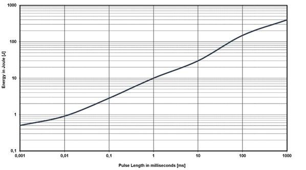
Example
Description of Pulse Energy Curve
Shape of pulse = e-function
Time between two pulses = 1 second
Pulse length = time constant of 1 tau (1 means ... tau = 1ms)
At 1 ms tau the PXP 200 with e.g. 1 Ω to 10 Ω can withstand an energy level of about 10 J, when the pulse pause time is ≥ 1s
At a symmetrical frequency > 1 kHz at pulse length ≥ 10 μs. the maximum applied pulse energy for PXP 200 is a result out of the nominal power 200 W divided by the operating frequency (at 85°C bottom case) (E = 200 W / F)
Pulse Power Curve (typical rating for PXP 200)
The power curve shows the max. possible power which can be applied for a certain duration. Referring to the same test procedure as described above.
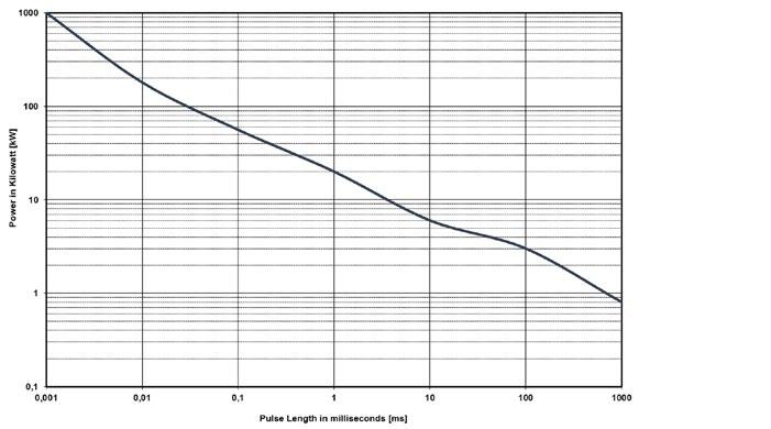
Example
Description of Pulse Power Curve
Shape of pulse = e-function
Time between two pulses = 1 second
Pulse length = time constant of 1 tau (1 means ... tau = 1ms)
For the time-constant of 1 ms you can apply about 20 kW max. (Pp = 2*E / τ)à, if the time between two such peaks is ≥ 1s
Flange Plate Power Resistors
Series LPP 250
250 W Power Resistor at 85°C Bottom Case
Miba Resistors general medium power resistor. Main applications are variable speed drives, power supplies, control devices, telecom, robotics, motor controls and other switching designs. Specials and custom designed components on request.
Features
multiple resistors in 1 package
Non-Inductive design
ROHS compliant
Materials in accordance with UL 94 V-0
T hermal interface management available (ask for details)
Version: fast-on (F) / solder pin (SP) / cable (C) possible (ask for details)
Technical Specifications
Resistance value on request
Resistance tolerance ±1 % to ±10 %
Temperature coefficient
1/1
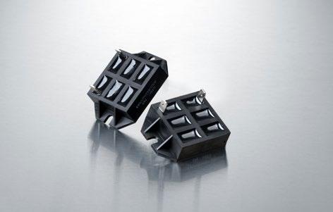
±250 ppm/°C (at +85°C ref. to +25°C) lower TCR on special request for limited ohmic values
Power rating up to 250 W at 85°C bottom case temperature (see configurations)
Short time overload 1.25x rated power at 85°C bottom case temperature for 10 s., ΔR = 0.4% max. (for conf. 1, 2 and 3)
Operating working voltage 1000 V DC up to 2000 V = "S"-version up to 2000 V + higher pulse capability = "U"-version
Partial discharge up to 2000 Vrms / 80pC (tests only on special request)
Voltage proof dielectric strength up to 4000 V DC against ground
Insulation resistance > 10 GΩ at 1000 V DC
Isolation voltage betweeen R1 & R2 & R3 500 V DC (1000 V DC on special request)
Heat resistance to cooling plate Rth < 0.35 K/W
Capacitance/mass 45 pF (typical), measuring frequency 10 kHz
Serial inductivity LPP-250 typical 40 nH, measuring frequency 10 kHz
Working temperature range -55°C to +155°C
Mounting - torque for base plate (static) 1.3 Nm to 1.5 Nm M4 screws
Weight ~23g
Dimensions in mm
Grouting
Marking
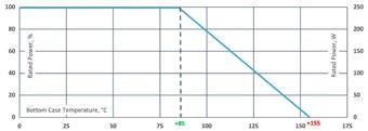
Derating (thermal resist.) LPP-250: 2.86 W/K (0.35 K/W) (for conf. 1, 2 and 3)
Best results can be reached by using a thermal transfer compound with a heat conductivity of at least 1 W/mK The fl atness of the cooling plate must be better than 0.05 mm overall. Surface roughness should not exceed 6.4 μm.
How to make a request
LPP-250-Configuration_Ohmic Value_ Tolerance
For example: LPP-250-1 4R7 5%
Example for higher working voltage: LPP-250-1-S 4R7 10%
"S"-version: special trimming process "U"-version: untrimmed
Configurations (P / package)
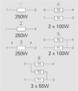
Version 5: ohmic value between contact 2 and 4 aprox. 3mΩ
Series WLL 320
Due to our Non-Inductive design, the WLL series is ideally suited for high-frequency and pulse-loading applications. Through direct mounting on a heat sink, significant cost advantage can be realized. Main applications are: variable speed drives, power supplies, control devices, telecommunications, robotics, motor controls and other switching devices.
Features
multiple resistors in 1 package
Non-Inductive design
ROHS compliant
Materials in accordance with UL 94 V-0
Thermal interface management available (ask for details)
Technical Specifications
Resistance value 0.1 Ω to 1 MΩ
Resistance tolerance ±1 % to ±10 %
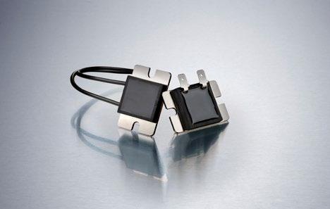
Temperature coefficient > 1R: ±250 ppm/°C (at +85°C ref. to +25°C) lower TCR on special request for limited ohmic values
Power rating
300 W at 25°C bottom case temperature
200 W at 85°C bottom case temperature
Short time overload 1.25x rated power at 85°C bottom case temperature for 10 s., ΔR = 0.4% max. (for conf. 1, 2 and 3)
Operating working voltage
500 V up to 1500 V = "S"-version up to 1500 V + higher pulse capability = "U"-version
Partial discharge up to 2000 Vrms / 80pC (only on special request)
Voltage proof dielectric strength up to 3000 V DC against ground
Insulation resistance > 10 GΩ at 1000 V DC
Isolation voltage betweeen R1 & R2 & R3 500 V DC (1000 V DC on special request)
Comparative Tracking Index (CTI) standard > 600 V
Heat resistance to cooling plate Rth < 0.35 K/W
Capacitance/mass 45 pF (typical), measuring frequency 10 kHz
Serial inductivity WLL-320 typical 40 nH, measuring frequency 10 kHz
Working temperature range -55°C to +155°C
Mounting - torque for base plate (static) 1.3 Nm to 1.5 Nm M4 screws
Standard cable type RADOX 4 GKW- AX 1800 V 0.5 mm²
Weight ~22 g (depending on type)
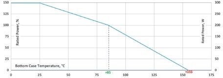
How to make a request
WLL-320_Configuration_Ohmic Value_ Tolerance
For example: WLL-320-2 1R 10% or WLL-320-2-C 10R 5%
Configurations (P / package)
"S"-version: special trimming process "U"-version: untrimmed 1x200 W
W
W
Version 5: ohmic value between contact 2 and 4 aprox. 3mΩ
Derating (thermal resist.) WLL-320: 2.86 W/K (0.35 K/W) (for conf. 1, 2 and 3)
Best results can be reached by using a thermal transfer compound with a heat conductivity of at least 1 W/mK. The flatness of the cooling plate must be better than 0.05 mm overall. Surface roughness should not exceed 6.4 μm.
Series WLL 320
Standard fast-on connection dimensions in mm [inches]
WLL-C (cable connection) dimensions in mm [inches] only possible for configuration 1
(standard cable length = 100mm, others on special request)
Series ACP 100
AECQ200 ready
100 W resistor 1/1
The 100 W resistor is a good solution for small pulses. The proven concept with Fast-On connection offers easy mounting on heat sinks and PCB.
Features
100 W power rating at 85°C bottom case temperature
Non-Inductive design
ROHS compliant
Materials in accordance with UL 94 V-0
T hermal interface management available (ask for details)
Technical Specifications
Resistance value 0.24 Ω to 1 MΩ
Resistance tolerance ±1 % to ±10 %
Temperature coefficient
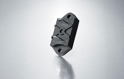
≥1 Ω: ±150 ppm/°C (+25°C to +105°C, ref. to +25°C)
<1 Ω: ±250 ppm/°C (+25°C to +105°C, ref. to +25°C)
Power rating 100 W at +85°C bottom case temperature
Maximum operating voltage 1000 V DC
Dielectric strength 3500 V DC
Insulation resistance min. 10 GΩ
Momentary overload
2 times rated power, but no more than 1.5 time max. continuous operating voltage, last 5s, ΔR ≤ ±(0.25%R + 0.001Ω)
Load life 1000 h at rated power, BCT at 85°C
ΔR ≤ ±(0.5%R + 0.001Ω)
Moisture resistance 56 days / 40°C, RH ≥ 95 %, ΔR ≤ ±(0.5%R + 0.001Ω)
Thermal schock
Terminal strength
Vibration, high frequency
MIL-Std.-202, method 107, Cond. F ΔR ≤ ±(0.3%R + 0.001Ω)
MIL-Std.-202, method 211, Cond. A (pull test) 2.4 N ΔR ≤ ±(0.2%R + 0.001Ω)
MIL-Std.-202, method 204, Cond. D ΔR ≤ ±(0.2%R + 0.001Ω)
Working temperature -55°C to +125°C
Installation M3 screw, max. torque 0.7 Nm Weight ~6 g
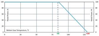
Derating (thermal resist.) ACP-100: 0.45 K/W
A thermal interface material with a specific thermal resistance >3,4W / (mK) and a printed thickness of <0,15mm shall be pre-applied on the resistor.
How to make a request
ACP-100_Ohmic Value_Tolerance
For example: ACP-100 50R 10%
Suggested Mounting Procedure:
1.) Position component and press down by hand
2.) Fix both mounting screws (M3) with 0.1 to 0.2 Nm torque
Dimensions in mm
3.) Apply final torque to mounting screws of 0.6 to 0.7 Nm
Series AXM
100 W Low Ohm Pulse Power Resistor - only configuration 1 possible
This model is designed for high pulse withstanding capabilities. The AXM series is usually used in areas where stringent pulse withstanding requirements are common such as welding equipment, variable speed drives and motor control and other switching devices.
Please let us know your exact pulse parameters to offer you the best option / design details.
Features
100 W operating power
Non-Inductive design
ROHS compliant
Materials in accordance with UL 94V-0
T hermal interface management available (ask for details)
Technical Specifications
Resistance value 0.05 Ω to 0.5 Ω
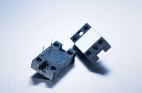
Resistance tolerance ±10 % standard ± 5 % on special request f. limited ohmic values
Temperature coefficient typical ±500 ppm/°C (at +85°C ref. to + 25°C)
Power rating 100 W at 85°C bottom case temperature
Operating working voltage up to 500 V (depending on pulse load scenario)
Dielectric strength 3 kV DC (1.5 kV AC, higher values on special request) between terminal and case
Working temperatur range -55°C to +155°C
Standard wire length L = 10 mm (other lengths available on special request)
Mounting - torque 1.0 Nm to 1.2 Nm Weight ~18 g
Suggested Mounting Procedure:
1.) Position component and press down by hand
2.) Fix both mounting screws (M4) with 0.1 to 0.2 Nm torque
3.) Apply final torque to mounting screws of 1.0 to 1.2 Nm
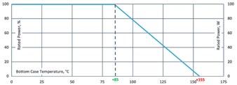
Best results can be reached by using a thermal transfer compound with a heat conductivity of at least 1 W/mK. The flatness of the cooling plate must be better than 0.05 mm overall. Surface roughness should not exceed 6.4 μm.
How to make a request AXM-1 B_Ohmic Value_Tolerance
For example: AXM-1 B 0R1 10%
Dimensions in mm [inches]
Flange Plate Power Resistor
Series RPS 100
Features
150 W operating power
Bottom case temperature ≤ 70°C
Single resistor configuration
Installation with M4 screw mounting
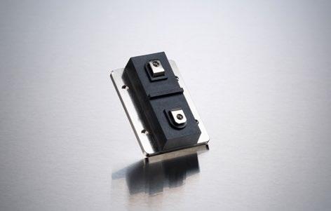
Technical Specifications
Resistance value 0.1 Ω to 1 MΩ
Resistance tolerance ±1 % to ±10 %
Temperature coefficient ±150 ppm/°C, lower on special request (referenced to 25 °C, ΔR taken at +108°C)
Power rating 150 W at +70°C (installed on heatsink) 10 W at +25°C free air
Maximum operating voltage 2000 V AC or 4000 V DC
Dielectric strength voltage 5 kV AC, 1 min.
Insulation resistance > 10 GΩ at 500 V DC
Capacitance / mass 45 pF
Contact installation M4 screw, max. torque 1 Nm
Base plate installation M4 screw, max. torque 3 Nm
Working temperature -55°C ~ +155°C
Weight ~65g
Dimensions in mm
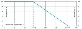
Derating (thermal resist.) RPS-100: 1.76 W/K (0.57 K/W)
How to make a request
RPS-100_Ohmic Value_Tolerance
For example: RPS-100 220R 5%
Applicable Standard
IEC60115-1: 2001 (GB/T5729-2003) MIL-STD-202
MIL-R-39009D
2xM4 screw
Ultra-High-Power Resistors
Series UXP®-350 (replaces
350 W resistor
Mainly used as a snubber resistor to compensate the C-R peaks in traction power supplies. Furthermore for speed drives, power supplies, control devices and robotics.
The easy mounting fixture guarantees an auto-calibrated pressure to the cooling plate of about 300 N.
Features
350 W operating power
Non-Inductive design
ROHS compliant
High insulation & partial discharge performance
Materials in accordance with UL 94 V-0
T hermal interface management available (ask for details)
Technical Specifications
the previous UXP-300)
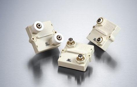
General Specifications
Resistance value 0.03 Ω to 1 MΩ (higher values on request)
Resistance tolerance ±5 % to ±10 % ±1 % to ±2 % on special request for limited ohmic values with the reduction of the max. power / pulse rating (ask for details)
Temperature coefficient
±500 ppm/°C (0.1 Ω to 0.12 Ω) standard ±150 ppm/°C (> 0.12 Ω to 1 MΩ) standard lower TCR on special request for limited ohmic values
Power rating 350 W at 85°C bottom case temperature
Short time overload 600 W at 70°C for 10s., ΔR = 0.4% max.
Operating working voltage 5000 V DC ≙ 3500 V AC RMS (50 Hz) higher voltage on request, not exceeding max. power
Maximum continuous current 150 A (HC or UHC version)
Dielectric strength
Partial discharge
7 kVrms / 50 Hz / 500 VA, test time 1 min. between terminal und case (up to 12 kVrms on request) voltages above 10 kVrms are tested at DC equivalent to avoid pre damage of component
4 kVrms < 10 pC (up to 7 kVrms < 10 pC on request) acc. to IEC 60270
Peak current up to 1500 A depending on pulse length and frequency (ask for details)
Insulation resistance > 10 GΩ at 1000 V
Single shot voltage up to 12 kV norm wave (1.5/50 μs)
Creeping distance > 42 mm (standard, higher on request)
Air distance > 14 mm (standard, higher on request)
Inductance ≤ 80 nH (typical), measuring frequency 10 kHz
Capacity/mass ≤ 110 pF (typical), measuring frequency 10 kHz
Capacity/parallel ≤ 40 pF (typical), measuring frequency 10 kHz
Operating temperature -55°C to +155°C
Mounting - torque for contacts 1.8 Nm to 2 Nm
Mounting - torque 1.6 Nm to 1.8 Nm M4 screws
Internal temperature sensor available on request PT-1000 / PT-100 / Type K / Type J (ask for details)
Cable variation available on request HV-cable / Flying leads (ask for details)
Standard cable type H&S Radox 9 GKW AX 1,5mm² (other cable types on special request)
Weight ~120 g
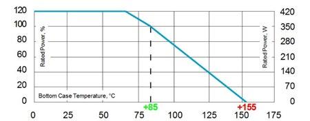
Electric support
Alumina metalized with Miba Resistors
ALTOX film on the bottom for improved heat transfer and optimum discharge
Encapsulation
Resin-filled epoxy casing with large creeping distance to mass, large air distance between the terminals and high insulation resistance (CTI 600)
Resistance Element
Special design for perfect current yield over the entire resistor area
Housing
Housings are made without color additives. The color definition is natural and can vary in different pigmentation
Contacts
Easy load connection with M4 and M5 screws
(Inch thread terminals on request)
Connector height available from 25 to 42 mm
Various sleeves for increasing creeping distance up to 85 mm or potted cable connections are available on request
Contacts standard M5 (M4 on special request - connection screw thread max. 7 mm)
Derating (thermal resist.) UXP®-350: 5 W/K (0.2 K/W)
Power rating: 350 W at 85°C bottom case temperature*
Please ask for detailed mounting procedure!
* This value is only applicable when using a thermal conduction to the heat sink Rth-cs<0.025 K/W. This value can be obtained by using a thermal transfer compound with a heat conductivity of at least 1 W/mK. The flatness of the cooling plate must be better than 0.05 mm overall. Surface roughness should not exceed 6.4 μm.
Series UXP®-350
Dimensions in inches [mm]
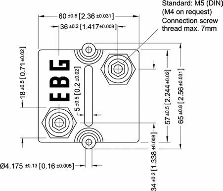
How to make a request
Standard terminal UXP-350_Ohmic Value_Tolerance_Terminal Height_Contact
For example
UXP-350 5R 10% 30/32 M5
Examples for optional terminals UXP-350 5R 10% 25/25 M5 or UXP-350-7 5R 10%
Borehole Distance
Test Specifications*
Please note most
Standard Terminals
Air distance: 14mm [0.5512] min. Creeping distance: 42mm [1.6535] min.
Terminal height 30/32
Standard
Terminal height 25/25
Optional
Terminal Options (for increased air & creeping distances) Other terminal dimensions available, contact for more information
]
UXP-350-9
Air distance: 25mm [0.984] min. Creeping distance: 83mm [3.267] min.
UXP-350-7
Air distance: 26.7mm [1.0512] min. Creeping distance: 50mm [1.968] min.
UXP-350-16
Air and creeping distance depends on
* The test methods are according to IEC 60068-2
** The tolerance drift is the possible change of the resistance value because of the certain test
Ultra-High-Power Resistors
Series UXP®-350
Pulse Energy Curve (typical rating for UXP-350 with 2R and 10 % tolerance)
Note: These energy values are reference values, depending on ohmic value and used resistive paste, a variation in max. energy load capability is possible
Test procedure
Every test resistor was mounted with thermal compound (0.9 W/mK) on a water cooled heatsink
Constant inlet water temperature: +50°C
The test time of each tested resistor: 10min.
Break time between two pulses: 1s.
To determine good / defect parts the ohmic value was measured before and after tests: a change of tolerance of more than 0.1% means defect
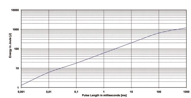
Example
Description of Pulse Energy Curve
Shape of pulse = e-function
Time between two pulses = 1 second
Pulse length = time constant of 1 tau (1 means ... tau = 1ms)
At 1 ms tau the UXP-350 with 2R can withstand an energy level of about 60 J, when the pulse pause time is ≥ 1s
At a symmetrical frequency > 1 kHz at pulse length ≥ 10 μs. the maximum applied pulse energy for UXP-350 is a result out of the nominal power 350 W divided by the operating frequency (at 85°C bottom case) (E = 350 W / F)
Pulse Power Curve (typical rating for UXP-350 with 2R and 10 % tolerance)
The power curve shows the max. possible power which can be applied for a certain duration. Referring to the same test procedure as described above.
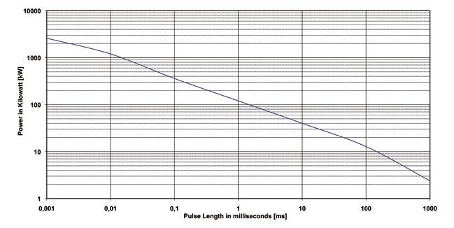
Example
Description of Pulse Power Curve
Shape of pulse = e-function
Time between two pulses = 1 second
Pulse length = time constant of 1 tau (1 means ... tau = 1ms)
For the time-constant of 1 ms you can apply about 120 kW max. (Pp = 2*E / τ)à, if the time between two such peaks is ≥ 1s
Series UXP®-600
600 W resistor, US Patent-No. 5,355,281
For variable speed drives, power supplies, control devices, robotics, motor control and other power designs, the easy mounting fixture assures an auto-calibrated pressure to the cooling plate of about 300 N.
Features
600 W operating power
Non-Inductive design
ROHS compliant
High insulation & partial discharge performance
Materials in accordance with UL 94 V-0
T hermal interface management available (ask for details)
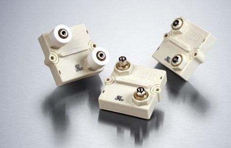
Technical Specifications
Resistance value 0.03 Ω to 1.5 MΩ (higher values on request)
Resistance tolerance ±5 % to ±10 % ±1 % to ±2 % on special request for limited ohmic values with the reduction of the max. power / pulse rating (ask for details)
Temperature coefficient
±500 ppm/°C (0.1 Ω to 0.2 Ω) standard ±150 ppm/°C (> 0.2 Ω to 1.5 MΩ) standard lower TCR on special request for limited ohmic values
Power rating 600 W at 85°C bottom case temperature
Short time overload 1000 W at 70°C for 10s., ΔR = 0.4% max.
Operating working voltage 5000 V DC ≙ 3500 V AC RMS (50 Hz) higher voltage on request, not exceeding max. power
Maximum continuous current 150 A (HC or UHC version)
Dielectric strength
Partial discharge
7 kVrms / 50 Hz / 500 VA, test time 1 min. between terminal und case (up to 12 kVrms on request) voltages above 10 kVrms are tested at DC equivalent to avoid pre damage of component
4 kVrms < 10 pC (up to 7 kVrms < 10 pC on request) acc. to IEC 60270
Peak current up to 1500 A depending on pulse length and frequency (ask for details)
Insulation resistance > 10 GΩ at 1000 V
Single shot voltage up to 12 kV norm wave (1.5/50 μs)
Creeping distance > 42mm (standard, higher on request)
Air distance > 14mm (standard, higher on request)
Inductance ≤ 80 nH (typical), measuring frequency 10 kHz
Capacity/mass ≤ 110 pF (typical), measuring frequency 10 kHz
Capacity/parallel ≤ 40 pF (typical), measuring frequency 10 kHz
Operating temperature -55°C to +155°C
Mounting - torque for contacts 1.8 Nm to 2 Nm
Mounting - torque 1.6 Nm to 1.8 Nm M4 screws
Internal temperature sensor available on request PT-1000 / PT-100 / Type K / Type J (ask for details)
Cable variation available on request HV-cable / Flying leads (ask for details)
Standard cable Type H&S Radox 9 GKW AX 1,5mm2 (other cable types on special request)
Weight ~120 g
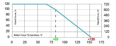
General Specifications
Electric support
Alumina metalized with Miba Resistors ALTOX film on the bottom for improved heat transfer and optimum discharge
Encapsulation
Resin-filled epoxy casing with large creeping distance to mass, large air distance between the terminals and high insulation resistance (CTI 600)
Resistance Element
Special design for low inductance and capacitance values. The element employs our special METOXFILM, which demonstrates stability while covering high wattage and pulse loading
Housing
Housings are made without color additives. The color definition is natural and can vary in different pigmentation
Contacts
Easy load connection with M4 and M5 screws (Inch thread terminals on request)
Connector height available from 25 to 42 mm
Various sleeves for increasing creeping distance up to 85 mm or potted cable connections are available on request
Contacts standard M5 (M4 on special request - connection screw thread max. 7 mm)
Derating (thermal resist.) UXP®-600: 8.33 W/K (0.12 K/W)
Power rating: 600 W at 85°C bottom case temperature*
Please ask for detailed mounting procedure! *
Series UXP®-600
Dimensions in mm [inches]
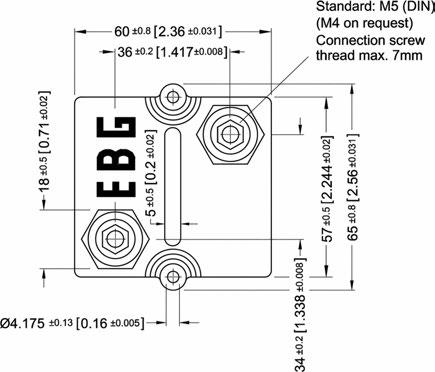
How to make a request
Standard terminal
UXP-600_Ohmic Value_Tolerance_Terminal Height_Contact
For example
UXP-600 5R 10% 30/32 M5
Examples for optional terminals UXP-600 5R 10% 25/25 M5 or UXP-600-7 5R 10%
Borehole Distance
Test Specifications*
Please
Standard Terminals
Air distance: 14mm [0.5512] min. Creeping distance: 42mm [1.6535] min
Terminal height 30/32
Standard
Terminal height 25/25
Optional
Terminal Options (for increased air & creeping distances) Other terminal dimensions available, contact for more information
]
UXP-600-9
Air distance: 25mm [0.984] min. Creeping distance: 83mm [3.267] min.
UXP-600-7
Air distance: 26.7mm [1.0512] min. Creeping distance: 50mm [1.968] min.
UXP-600-16
Air and creeping distance depends on length of HV-cable
* The test methods are according to IEC 60068-2
** The tolerance drift is the possible change of the resistance value because of the certain test
Ultra-High-Power Resistors
Series UXP®-600
Pulse Energy Curve (typical rating for UXP-600 with 10R and 10 % tolerance)
Note: These energy values are reference values, depending on ohmic value and used resistive paste, a variation in max. energy load capability is possible
Test procedure
Every test resistor was mounted with thermal compound (0.9 W/mK) on a water cooled heatsink
Constant inlet water temperature: +50°C
The test time of each tested resistor: 10min.
Break time between two pulses: 1s.
To determine good / defect parts the ohmic value was measured before and after tests: a change of tolerance of more than 0.1% means defect
Description of Pulse Energy Curve
Shape of pulse = e-function
Time between two pulses = 1 second
Pulse length = time constant of 1 tau (1 means ... tau = 1ms)
Example
At 1 ms tau the UXP-600 with 10R can withstand an energy level of about 60 J, when the pulse pause time is ≥ 1s
At a symmetrical frequency > 1 kHz at pulse length ≥ 10 μs. the maximum applied pulse energy for UXP-600 is a result out of the nominal power 600 W divided by the operating frequency (at 85°C bottom case) (E = 600 W / F)
Pulse Power Curve (typical rating for UXP-600 with 10R and 10 % tolerance)
The power curve shows the max. possible power which can be applied for a certain duration. Referring to the same test procedure as described above.
Description of Pulse Power Curve
Shape of pulse = e-function
Time between two pulses = 1 second
Pulse length = time constant of 1 tau (1 means ... tau = 1ms)
Example
For the time-constant of 1 ms you can apply about 120 kW max. (Pp = 2*E / τ)à, if the time between two such peaks is ≥ 1s
Series UXP®-800
800 W resistor, US Patent-No. 5,355,281
For variable speed drives, power supplies, control devices, robotics, motor control and other power designs, the easy mounting fixture assures an auto-calibrated pressure to the cooling plate of about 300 N.
Features
800 W operating power
Non-Inductive design
ROHS compliant
High insulation & partial discharge performance
Materials in accordance with UL 94 V-0
T hermal interface management available (ask for details)
Technical Specifications
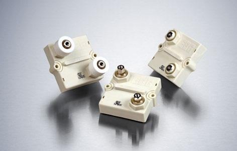
General Specifications
Resistance value 0.03 Ω to 1 MΩ (higher values on request)
Resistance tolerance ±5 % to ±10 % ±1 % to ±2 % on special request for limited ohmic values with the reduction of the max. power / pulse rating (ask for details)
Temperature coefficient
±500 ppm/°C (0.1 Ω to 0.25Ω) standard
±150 ppm/°C (> 0.25 Ω to 1 MΩ) standard lower TCR on special request for limited ohmic values
Power rating 800 W at 85°C bottom case temperature
Short time overload 1000 W at 70°C for 10s., ΔR = 0.4% max.
Operating working voltage 5000 V DC ≙ 3500 V AC RMS (50 Hz) higher voltage on request, not exceeding max. power
Maximum continuous current 150 A (HC or UHC version)
Dielectric strength
Partial discharge
7 kVrms / 50 Hz / 500 VA, test time 1 min. between terminal und case (up to 12 kVrms on request) voltages above 10 kVrms are tested at DC equivalent to avoid pre damage of component
4 kVrms < 10 pC (up to 7 kVrms < 10 pC on request) acc. to IEC 60270
Peak current up to 1500 A depending on pulse length and frequency (ask for details)
Insulation resistance > 10 GΩ at 1000 V
Single shot voltage up to 12 kV norm wave (1.5/50 μs)
Creeping distance > 42 mm (standard, higher on request)
Air distance > 14 mm (standard, higher on request)
Inductance ≤ 80 nH (typical), measuring frequency 10 kHz
Capacity/mass ≤ 140 pF (typical), measuring frequency 10 kHz
Capacity/parallel ≤ 40 pF (typical), measuring frequency 10 kHz
Operating temperature -55°C to +155°C
Mounting - torque for contacts 1.8 Nm to 2 Nm
Mounting - torque 1.6 Nm to 1.8 Nm M4 screws
Internal temperature sensor available on request PT-1000 / PT-100 / Type K / Type J (ask for details)
Cable variation available on request HV-cable / Flying leads (ask for details)
Standard cable type H&S Radox 9 GKW AX 1,5mm2 (other cable types on special request) Weight ~120 g
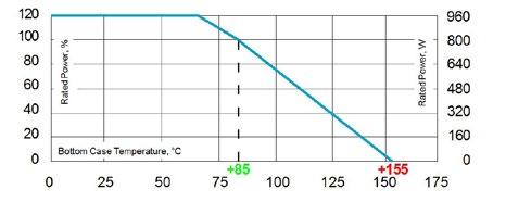
Electric support
Alumina metalized with Miba Resistors ALTOX film on the bottom for improved heat transfer and optimum discharge
Encapsulation
Resin-filled epoxy casing with large creeping distance to mass, large air distance between the terminals and high insulation resistance (CTI 600)
Resistance Element
Special design for low inductance and capacitance values. The element employs our special METOXFILM, which demonstrates stability while covering high wattage and pulse loading
Housing
Housings are made without color additives. The color definition is natural and can vary in different pigmentation
Contacts
Easy load connection with M4 and M5 screws (Inch thread terminals on request)
Connector height available from 25 to 42 mm
Various sleeves for increasing creeping distance up to 85 mm or potted cable connections are available on request
Contacts standard M5 (M4 on special request - connection screw thread max. 7 mm)
Derating (thermal resist.) UXP®-800: 11.43 W/K (0.0875 K/W)
Power rating: 800 W at 85°C bottom case temperature*
Please ask for detailed mounting procedure!
Series UXP®-800
Dimensions in mm [inches]
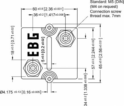
How to make a request
Standard terminal UXP-800_Ohmic Value_Tolerance_Terminal Height_Contact
For example
UXP-800 5R 10% 30/32 M5
Examples for optional terminals
UXP-800 5R 10% 25/25 M5 or UXP-800-7 5R 10%
Borehole Distance
Test Specifications*
Please note most
Standard Terminals
Air distance: 14mm [0.5512] min. Creeping distance: 42mm [1.6535] min.
Terminal height 30/32
Standard
Terminal height 25/25
Optional
Terminal Options (for increased air & creeping distances) Other terminal dimensions available, contact for more information
]
UXP-800-9
Air distance: 25mm [0.984] min. Creeping distance: 83mm [3.267] min.
UXP-800-7
Air distance: 26.7mm [1.0512] min. Creeping distance: 50mm [1.968] min.
UXP-800-16
Air and creeping distance depends on length of HV-cable
* The test methods are according to IEC 60068-2
** The tolerance drift is the possible change of the resistance value because of the certain test
Series UXP®-800
Pulse Energy Curve (typical rating for UXP-800 with 2R and 10 % tolerance)
Note: These energy values are reference values, depending on ohmic value and used resistive paste, a variation in max. energy load capability is possible
Test procedure
Every test resistor was mounted with thermal compound (0.9 W/mK) on a water cooled heatsink
Constant inlet water temperature: +50°C
The test time of each tested resistor: 10min.
Break time between two pulses: 1s.
To determine good / defect parts the ohmic value was measured before and after tests: a change of tolerance of more than 0.1% means defect
Description of Pulse Energy Curve
Shape of pulse = e-function
Time between two pulses = 1 second
Pulse length = time constant of 1 tau (1 means ... tau = 1ms)
Example
At 1 ms tau the UXP-800 with 2R can withstand an energy level of about 70 J, when the pulse pause time is ≥ 1s
At a symmetrical frequency > 1 kHz at pulse length ≥ 10 μs. the maximum applied pulse energy for UXP-800 is a result out of the nominal power 800 W divided by the operating frequency (at 85°C bottom case) (E = 800 W / F)
Pulse Power Curve (typical rating for UXP-800 with 2R and 10 % tolerance)
The power curve shows the max. possible power which can be applied for a certain duration. Referring to the same test procedure as described above.
Description of Pulse Power Curve
Shape of pulse = e-function
Time between two pulses = 1 second
Pulse length = time constant of 1 tau (1 means ... tau = 1ms)
Example
For the time-constant of 1 ms you can apply about 140 kW max. (Pp = 2*E / τ)à, if the time between two such peaks is ≥ 1s
Ultra-High-Power Resistors
Series UXP®-1000
1000 W resistor at 50°C bottom case
For variable speed drives, power supplies, control devices, robotics, motor control and other power designs, the easy mounting fixture assures an auto-calibrated pressure to the cooling plate of about 300 N.
Features
1000 W operating power
Non-Inductive design
ROHS compliant
High insulation & partial discharge performance
Materials in accordance with UL 94 V-0
T hermal interface management available (ask for details)
Technical Specifications
Resistance value 0.03 Ω to 1 MΩ
Resistance tolerance ±5 % to ±10 %
Temperature coefficient
General Specifications
Electric support
±500 ppm/°C (0.1 Ω to 0.25Ω) standard ±150 ppm/°C (> 0.25 Ω to 1 MΩ standard lower TCR on special request for limited ohmic values
Power rating 1000 W at 50°C bottom case temperature
Short time overload 1200 W at 30°C for 10s., ΔR = 0.4% max.
Operating working voltage 5000 V DC ≙ 3500 V AC RMS (50 Hz) higher voltage on request, not exceeding max. power
Maximum continuous current 150 A (HC or UHC version)
Dielectric strength
Partial discharge
7 kVrms / 50 Hz / 500 VA, test time 1 min. between terminal und case (up to 12 kVrms on request) voltages above 10 kVrms are tested at DC equivalent to avoid pre damage of component
4 kVrms < 10 pC (up to 7 kVrms < 10 pC on request) acc. to IEC 60270
Peak current up to 1500 A depending on pulse length and frequency (ask for details)
Insulation resistance > 10 GΩ at 1000 V
Single shot voltage up to 12 kV norm wave (1.5/50 μs)
Creeping distance > 42 mm (standard, higher on request)
Air distance > 14 mm (standard, higher on request)
Inductance ≤ 80 nH (typical), measuring frequency 10 kHz
Capacity/mass ≤ 140 pF (typical), measuring frequency 10 kHz
Capacity/parallel ≤ 40 pF (typical), measuring frequency 10 kHz
Operating temperature -55°C to +155°C
Mounting - torque for contacts 1.8 Nm to 2 Nm
Mounting - torque 1.6 Nm to 1.8 Nm M4 screws
Internal temperature sensor available on request PT-1000 / PT-100 / Type K / Type J (ask for details)
Cable variation available on request HV-cable / Flying leads (ask for details)
Standard cable type H&S Radox 9 GKW AX 1,5mm2 (other cable types on special request)
Weight ~120 g
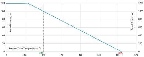
Alumina metalized with Miba Resistors ALTOX film on the bottom for improved heat transfer and optimum discharge
Encapsulation
Resin-filled epoxy casing with large creeping distance to mass, large air distance between the terminals and high insulation resistance (CTI 600)
Resistance Element
Special design for low inductance and capacitance values. The element employs our special METOXFILM, which demonstrates stability while covering high wattage and pulse loading
Housing
Housings are made without color additives. The color definition is natural and can vary in different pigmentation
Contacts
Easy load connection with M4 and M5 screws (Inch thread terminals on request)
Connector height available from 25 to 42 mm
Various sleeves for increasing creeping distance up to 85 mm or potted cable connections are available on request
Contacts standard M5 (M4 on special request - connection screw thread max. 7 mm)
Derating (thermal resist.) UXP®-1000: 9.52 W/K (0.105 K/W)
Power rating: 1000 W at 50°C bottom case temperature*
Please ask for detailed mounting procedure!
* This value is only applicable when using a thermal conduction to the heat sink Rth-cs<0.025 K/W. This value can be obtained by using a thermal transfer compound with a heat conductivity of at least 1 W/mK. The flatness of the cooling plate must be better than 0.05 mm overall. Surface roughness should not exceed 6.4 μm.
Series UXP®-1000
Dimensions in mm [inches]
How to make a request
Standard terminal
UXP-1000_Ohmic Value_Tolerance_Terminal Height_Contact
For example
UXP-1000 5R 10% 30/32 M5
Examples for optional terminals
UXP-1000 5R 10% 25/25 M5 or UXP-1000-7 5R 10%
Borehole Distance
Test Specifications*
Please
Standard Terminals
Air distance: 14mm [0.5512] min. Creeping distance: 42mm [1.6535] min.
Terminal height 30/32 Standard
Terminal height 25/25 Optional
Terminal Options (for increased air & creeping distances) Other terminal dimensions available, contact for more information
UXP-1000-9
Air distance: 25mm [0.984] min. Creeping distance: 83mm [3.267] min.
UXP-1000-7
Air distance: 26.7mm [1.0512] min. Creeping distance: 50mm [1.968] min.
UXP-1000-16
Air and creeping distance depends on length of HV-cable
* The test methods are according to IEC 60068-2
** The tolerance drift is the possible change of the resistance value because of the certain test
Ultra-High-Power Resistors
Series UXP®-2000
2000 W resistor at 125°C bottom case
For variable speed drives, power supplies, control devices, robotics, motor control and other power designs, the easy mounting fixture assures an auto-calibrated pressure to the cooling plate of about 300 N.
Features
2000 W operating power
Non-Inductive design
ROHS compliant
High insulation & partial discharge performance
Materials in accordance with UL 94 V-0
T hermal interface management available (ask for details)
Technical Specifications
Resistance value 0.1 Ω to 6 KΩ (higher values on request)
Resistance tolerance ±5 % to ±10 %
Temperature coefficient ±250 ppm/°C standard lower TCR on special request for limited ohmic values
Power rating 2000 W at 125°C bottom case temperature resp. 60°C heat sink temperature
Short time overload 2400 W at 70°C for 10s., ΔR = 0.4% max.
Operating working voltage 5000 V DC ≙ 3500 V AC RMS (50 Hz) higher voltage on request, not exceeding max. power
Maximum continuous current 150 A (HC or UHC version)
Dielectric strength
7 kVrms / 50 Hz / 500 VA, test time 1 min. between terminal und case (up to 12 kVrms on request) voltages above 10 kVrms are tested at DC equivalent to avoid pre damage of component
Partial discharge 4 kVrms < 10 pC (up to 7 kVrms < 10 pC on request) acc. to IEC 60270
Pulse peak current up to 1500 A depending on pulse length and frequency (ask for details)
Insulation resistance > 10 GΩ at 1000 V
Single shot voltage up to 12 kV norm wave (1.5/50 μs)
Creeping distance > 42 mm (standard, higher on request)
Air distance > 14 mm (standard, higher on request)
Inductance ≤ 80 nH (typical), measuring frequency 10 kHz
Capacity/mass ≤ 120 pF (typical), measuring frequency 10 kHz
Capacity/parallel ≤ 40 pF (typical), measuring frequency 10 kHz
Operating temperature -55°C to +155°C
Mounting - torque for contacts 1.8 Nm to 2 Nm
Mounting - torque 1.6 Nm to 1.8 Nm M4 screws
Internal temperature sensor available on request PT-1000 / PT-100 / Type K / Type J (ask for details)
Cable variation available on request HV-cable / Flying leads (ask for details)
Standard cable type H&S Radox 9 GKW AX 1,5mm2 (other cable types on special request)
Suggested storage condition in dark ambient at > 0°C to + 85°C; max. 80%rel. humidity for 12 months
-> DO NOT remove the resistor from the original packing until you are ready to mount
Weight ~100 g
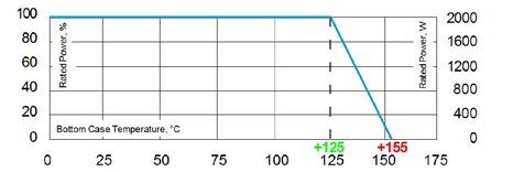
General Specifications
Electric support
Alumina metalized with Miba Resistors ALTOX film on the bottom for improved heat transfer and optimum discharge
Encapsulation
Resin-filled epoxy casing with large creeping distance to mass, large air distance between the terminals and high insulation resistance (CTI 600)
Resistance Element
Special design for low inductance and capacitance values. The element employs our special METOXFILM, which demonstrates stability while covering high wattage and pulse loading
Housing
Housings are made without color additives. The color definition is natural and can vary in different pigmentation
Contacts
Easy load connection with M4 and M5 screws (Inch thread terminals on request)
Connector height available from 25 to 42 mm
Various sleeves for increasing creeping distance up to 85 mm or potted cable connections are available on request
Contacts standard M5 (M4 on special request - connection screw thread max. 7 mm)
Derating (thermal resist.) UXP®-2000: 66.6 W/K (0.015 K/W)
Power rating: 2000 W at 125°C bottom case temperature*
Please ask for detailed mounting procedure!
* Best results can be reached by using a thermal transfer compound with a heat conductivity of at least 2.9 W/mk. The flatness of the cooling plate must be better than 0.05 mm overall. Surface roughness should not exceed 6.4 μm.
Series UXP®-2000
Dimensions in mm [inches]
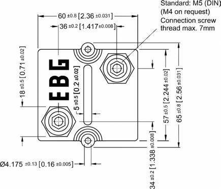
How to make a request
Standard terminal UXP-2000_Ohmic Value_Tolerance_Terminal Height_Contact
For example
UXP-2000 10R 10% 30/32 M5
Examples for optional terminals UXP-2000 24R 10% 25/25 M5
Borehole Distance
Test Specifications*
Standard Terminals
Air distance: 14mm [0.5512] min. Creeping distance: 42mm [1.6535] min.
Terminal height 30/32
Standard
Terminal height 25/25
Optional
Terminal Options (for increased air & creeping distances) Other terminal dimensions available, contact for more information
UXP-2000-9
Air distance: 25mm [0.984] min. Creeping distance: 83mm [3.267] min.
UXP-2000-7
Air distance: 26.7mm [1.0512] min. Creeping distance: 50mm [1.968] min.
UXP-2000-16
Air and creeping distance depends on length of HV-cable
Please note most all of our UXP customers have their own custom designed drawing. Therefore please do not hesitate to discuss your special needs with the local representative or contact us directly.
* The test methods are according to IEC 60068-2
** The tolerance drift is the possible change of the resistance value because of the certain test
Series UXP®-2500
2500 W resistor at 117.5°C bottom case
For variable speed drives, power supplies, control devices, robotics, motor control and other power designs, the easy mounting fixture assures an auto-calibrated pressure to the cooling plate of about 300 N.
Features
2500 W operating power
Non-Inductive design
ROHS compliant
High insulation & partial discharge performance
Materials in accordance with UL 94 V-0
T hermal interface management available (ask for details)
Technical Specifications
Resistance value 0.1 Ω to 6 KΩ
Resistance tolerance ±5 % to ±10 %
Temperature coefficient ±250 ppm/°C standard
General Specifications
Electric support
Alumina metalized with Miba Resistors ALTOX film on the bottom for improved heat transfer and optimum discharge
Power rating 2500 W at 117.5°C bottom case temperature
Short time overload 3000 W at 70°C for 10s., ΔR = 0.4% max.
Operating working voltage 5000 V DC ≙ 3500 V AC RMS (50 Hz) higher voltage on request, not exceeding max. power
Maximum continuous current 150 A (HC or UHC version)
Dielectric strength
7 kVrms / 50 Hz / 500 VA, test time 1 min. between terminal und case (up to 12 kVrms on request) voltages above 10 kVrms are tested at DC equivalent to avoid pre damage of component
Partial discharge 4 kVrms < 10 pC (up to 7 kVrms < 10 pC on request) acc. to IEC 60270
Peak current up to 1500 A depending on pulse length and frequency (ask for details)
Insulation resistance > 10 GΩ at 1000 V
Single shot voltage up to 12 kV norm wave (1.5/50 μs)
Creeping distance > 42 mm (standard, higher on request)
Air distance > 14 mm (standard, higher on request)
Inductance ≤ 80 nH (typical), measuring frequency 10 kHz
Capacity/mass ≤ 140 pF (typical), measuring frequency 10 kHz
Capacity/parallel ≤ 40 pF (typical), measuring frequency 10 kHz
Operating temperature -55°C to +155°C
Mounting - torque for contacts 1.8 Nm to 2 Nm
Mounting - torque 1.6 Nm to 1.8 Nm M4 screws
Internal temperature sensor available on request PT-1000 / PT-100 / Type K / Type J (ask for details)
Cable variation available on request HV-cable / Flying leads (ask for details)
Standard cable type H&S Radox 9 GKW AX 1,5mm2 (other cable types on special request)
Weight ~120 g
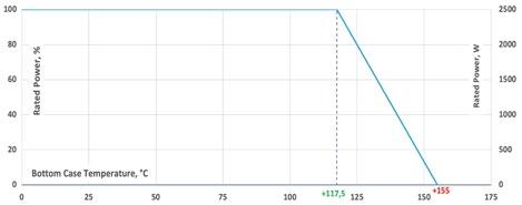
Encapsulation
Resin-filled epoxy casing with large creeping distance to mass, large air distance between the terminals and high insulation resistance (CTI 600)
Resistance Element
Special design for low inductance and capacitance values. The element employs our special METOXFILM, which demonstrates stability while covering high wattage and pulse loading
Housing
Housings are made without color additives. The color definition is natural and can vary in different pigmentation
Contacts
Easy load connection with M4 and M5 screws (Inch thread terminals on request)
Connector height available from 25 to 42 mm
Various sleeves for increasing creeping distance up to 85 mm or potted cable connections are available on request
Contacts standard M5 (M4 on special request - connection screw thread max. 7 mm)
Derating (thermal resist.) UXP®-2500: 66.6 W/K (0.015 K/W)
Power rating: 2500 W at 117.5°C bottom case temperature*
Please ask for detailed mounting procedure!
* This value is only applicable when using a thermal conduction to the
This
2.9 W/mK.
Series UXP®-2500
Dimensions in mm [inches]
How to make a request
Standard terminal UXP-2500_Ohmic Value_Tolerance_Terminal Height_Contact
For example
UXP-2500 5R 10% 30/32 M5
Examples for optional terminals
UXP-2500 5R 10% 25/25 M5 or UXP-2500-7 5R 10%
Borehole Distance
Test Specifications*
Please note
Standard Terminals
Air distance: 14mm [0.5512] min. Creeping distance: 42mm [1.6535] min.
Terminal height 30/32 Standard
Terminal height 25/25 Optional
Terminal Options (for increased air & creeping distances) Other terminal dimensions available, contact for more information
UXP-2500-9
Air distance: 25mm [0.984] min. Creeping distance: 83mm [3.267] min.
UXP-2500-7
Air distance: 26.7mm [1.0512] min. Creeping distance: 50mm [1.968] min.
UXP-2500-16
Air and creeping distance depends on length of HV-cable
* The test methods are according to IEC 60068-2
** The tolerance drift is the possible change of the resistance value because of the certain test
Series UXP®-3000
3000 W resistor at 110°C bottom case
For variable speed drives, power supplies, control devices, robotics, motor control and other power designs, the easy mounting fixture assures an auto-calibrated pressure to the cooling plate of about 300 N.
Features
3000 W operating power
Non-Inductive design
ROHS compliant
High insulation & partial discharge performance
Materials in accordance with UL 94 V-0
T hermal interface management available (ask for details)
Technical Specifications
Weight ~120 g Ultra-High-Power
Resistance value 0.1 Ω to 6 KΩ
Resistance tolerance ±5 % to ±10 %
Temperature coefficient ±250 ppm/°C standard
General Specifications
Electric support
Alumina metalized with Miba Resistors ALTOX film on the bottom for improved heat transfer and optimum discharge
Power rating 3000 W at 110°C bottom case temperature
Short time overload 3600 W at 70°C for 10s., ΔR = 0.4% max.
Operating working voltage 5000 V DC ≙ 3500 V AC RMS (50 Hz) higher voltage on request, not exceeding max. power
Maximum continuous current 150 A (HC or UHC version)
Dielectric strength
7 kVrms / 50 Hz / 500 VA, test time 1 min. between terminal und case (up to 12 kVrms on request) voltages above 10 kVrms are tested at DC equivalent to avoid pre damage of component
Partial discharge 4 kVrms < 10 pC (up to 7 kVrms < 10 pC on request) acc. to IEC 60270
Peak current up to 1500 A depending on pulse length and frequency (ask for details)
Insulation resistance > 10 GΩ at 1000 V
Single shot voltage up to 12 kV norm wave (1.5/50 μs)
Creeping distance > 42 mm (standard, higher on request)
Air distance > 14 mm (standard, higher on request)
Inductance ≤ 80 nH (typical), measuring frequency 10 kHz
Capacity/mass ≤ 140 pF (typical), measuring frequency 10 kHz
Capacity/parallel ≤ 40 pF (typical), measuring frequency 10 kHz
Operating temperature -55°C to +155°C
Mounting - torque for contacts 1.8 Nm to 2 Nm
Mounting - torque 1.6 Nm to 1.8 Nm M4 screws
Internal temperature sensor available on request PT-1000 / PT-100 / Type K / Type J (ask for details)
Cable variation available on request HV-cable / Flying leads (ask for details)
Standard cable type H&S Radox 9 GKW AX 1,5mm2 (other cable types on special request)
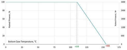
Encapsulation
Resin-filled epoxy casing with large creeping distance to mass, large air distance between the terminals and high insulation resistance (CTI 600)
Resistance Element
Special design for low inductance and capacitance values. The element employs our special METOXFILM, which demonstrates stability while covering high wattage and pulse loading
Housing
Housings are made without color additives. The color definition is natural and can vary in different pigmentation
Contacts
Easy load connection with M4 and M5 screws (Inch thread terminals on request)
Connector height available from 25 to 42 mm
Various sleeves for increasing creeping distance up to 85 mm or potted cable connections are available on request
Contacts standard M5 (M4 on special request - connection screw thread max. 7 mm)
Derating (thermal resist.) UXP®-3000: 66.6 W/K (0.015 K/W)
Power rating: 3000 W at 110°C bottom case temperature*
Please ask for detailed mounting procedure!
* This value is only applicable when using a thermal conduction to the
W/mK.
not exceed 6.4 μm.
Series UXP®-3000
Dimensions in mm [inches]
How to make a request
Standard terminal UXP-3000_Ohmic Value_Tolerance_Terminal Height_Contact
For example
UXP-3000 5R 10% 30/32 M5
Examples for optional terminals
UXP-3000 5R 10% 25/25 M5 or UXP-3000-7 5R 10%
Borehole Distance
Test Specifications*
Please note
Standard Terminals
Air distance: 14mm [0.5512] min. Creeping distance: 42mm [1.6535] min.
Terminal height 30/32 Standard
Terminal height 25/25 Optional
Terminal Options (for increased air & creeping distances) Other terminal dimensions available, contact for more information
UXP-3000-9
Air distance: 25mm [0.984] min. Creeping distance: 83mm [3.267] min.
UXP-3000-7
Air distance: 26.7mm [1.0512] min. Creeping distance: 50mm [1.968] min.
UXP-3000-16
Air and creeping distance depends on length of HV-cable
* The test methods are according to IEC 60068-2
** The tolerance drift is the possible change of the resistance value because of the certain test
Series UPT®-400
Ultra-High-Power Resistor s
Ultra-High-Power Resistor s
400 W resistor, US Patent-No. 5,355,281
Series UPT-40 0
Series UPT-40 0
4 0 0 W resis tor, US Patent- No. 5, 3 55, 281
4 0 0 W resis tor, US Patent- No. 5, 3 55, 281
For variable sp ee d drive s, p ower supplie s, c ontrol devic e s, rob otic s, motor c ontrol and other p ower de signs, the easy
For variable sp ee d drive s, p ower supplie s, c ontrol devic e s, rob otic s, motor c ontrol and other p ower de signs, the easy
c ooling pla te of ab out 120 to 16 0 N
c ooling pla te of ab out 120 to 16 0 N
For variable speed drives, power supplies, control devices, robotics, motor control and other power designs, the easy mounting fixture assures a pressure of the cooling plate of about 300 N.
Fea ture s
Fea ture s
Features
4 0 0 W op era ting p ower
4 0 0 W op era ting p ower
400 W operating power
Non - Induc tive de sign
Non - Induc tive de sign
Non-Inductive design
ROHS c ompliant
ROHS c ompliant
ROHS compliant
High insula tion & par tial dis c harge p er formanc e
High insula tion & par tial dis c harge p er formanc e
Ma terials in ac c oradanc e w ith UL 9 4 V- 0
High insulation & partial discharge performance
Ma terials in ac c oradanc e w ith UL 9 4 V- 0
Materials in accoradance with UL 94 V-0
Re sis tor is als o available w ith pr eapplie d P CM (Phas e Change Ma terial) (as k for de t ails)
Re sis tor is als o available w ith pr eapplie d P CM (Phas e Change Ma terial) (as k for de t ails)
T hermal interface management available (ask for details)
Technical Specifications
R e s i s t a n c e va l
Resistance value 0.5 Ω to 1 MΩ
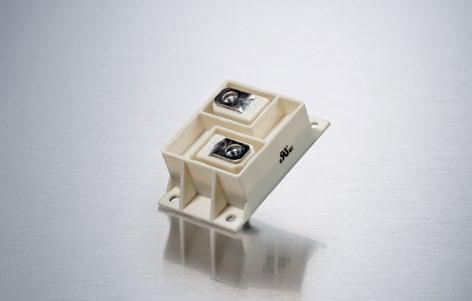
General Specifications
E n c a p s ul a t ion
E n c a p s ul a t ion
±10 % to ±5 % ±2 % to ±1 % on special request for limited ohmic values with the reduction of the max. power / pulse rating (ask for details)
R e s i s t a n c e to l e r a n c e ±10 % to ±5 % ±2 % to ±1 % on special request for limited ohmic values with the reduction of the max. power / pulse rating (ask for details)
Resistance tolerance ±5 % to ±10 % ±1 % to ±2 % on special request for limited ohmic values with the reduction of the max. power / pulse rating (ask for details)
±150 ppm/°C lower TCR on special request for limited ohmic values
Encapsulation
Re sin - lle d ep ox y c asing w ith large cre eping dis t anc e to mas s, large air dis t anc e b e t we en the terminals and high insula tion
Temperature coefficient ±150 ppm/°C lower TCR on special request for limited ohmic values
±150 ppm/°C lower TCR on special request for limited ohmic values
Powe r r a ti ng 400 W at 85°C bottom case temperature
Powe r r a ti ng 400 W at 85°C bottom case temperature
Power rating 400 W at 85°C bottom case temperature
Sho r t ti me ove r l oa d 700 W at 70°C for 10sec., ∆R = 0.4 % max.
Sho r t ti me ove r l oa d 700 W at 70°C for 10sec., ∆R = 0.4 % max.
Short time overload 700 W at 70°C for 10s., ΔR = 0.4 % max.
M a x i mum wor k i n g vo l t ag e 5,000 V DC = 3.500 V AC RMS (50 Hz) higher voltage on request, not exceeding max. power
Operating working voltage 5000 V DC ≙ 3500 V AC RMS (50 Hz) higher voltage on request, not exceeding max. power
M a x i mum wor k i n g vo l t ag e 5,000 V DC = 3.500 V AC RMS (50 Hz) higher voltage on request, not exceeding max. power
E l e c t r i c s t r e ng t h vo l t ag e 7 kVrms / 50 Hz / 500 VA, test time 1 min. (up to 12 kVrms on request) voltages above 10 kVrms are tested at DC equivalent to avoid pre damage of component terminal and case
Dielectric strength
E l e c t r i c s t r e ng t h vo l t ag e 7 kVrms / 50 Hz / 500 VA, test time 1 min. (up to 12 kVrms on request) voltages above 10 kVrms are tested at DC equivalent to avoid pre damage of component terminal and case
7 kVrms / 50 Hz / 500 VA, test time 1 min. between terminal und case (up to 12 kVrms on request) voltages above 10 kVrms are tested at DC equivalent to avoid pre damage of component
Pa r t i a l d i s c h a r g e 4 kVrms < 10 pC (up to 7 kVrms < 10 pC on request) acc. to IEC 60270
Partial discharge
I n s u l a t i on r e s i s t a n c e > 10 GΩ at 1,000 V
4 kVrms < 10 pC (up to 7 kVrms < 10 pC on request) acc. to IEC 60270
Pa r t i a l d i s c h a r g e 4 kVrms < 10 pC (up to 7 kVrms < 10 pC on request) acc. to IEC 60270
I n s u l a t i on r e s i s t a n c e > 10 GΩ at 1,000 V
Insulation resistance > 10 GΩ at 1000 V
S i ng l e s ho t vo l t ag e up to 12 kV norm wave (1.5/50 μsec)
S i ng l e s ho t vo l t ag e up to 12 kV norm wave (1.5/50 μsec)
Single shot voltage up to 12 kV norm wave (1.5/50 μs)
I nd u c t a n c e ≥ 80 nH (typical), measuring frequency 10 kHz
I nd u c t a n c e ≥ 80 nH (typical), measuring frequency 10 kHz
Inductance ≤ 80 nH (typical), measuring frequency 10 kHz
Ca p a c i t y/ma s s ≥ 110 pF (typical), measuring frequency 10 kHz
Ca p a c i t y/ma s s ≥ 110 pF (typical), measuring frequency 10 kHz
Capacity/mass ≤ 110 pF (typical), measuring frequency 10 kHz
C a p a c i t y/p ara l l e l ≥ 40 pF (typical), measuring frequency 10 kHz
O p e r a ti ng te m pe r a t u r e -55°C to +155°C
C a p a c i t y/p ara l l e l ≥ 40 pF (typical), measuring frequency 10 kHz
Capacity/parallel ≤ 40 pF (typical), measuring frequency 10 kHz
O p e r a ti ng te m pe r a t u r e -55°C to +155°C
M o un ti ng - ma x to r q u e fo r c on t a c t s 2 Nm
Operating temperature -55°C to +155°C
M o un ti ng - ma x to r q u e fo r c on t a c t s 2 Nm
Mounting - torque for contacts 1.8 Nm to 2 Nm, screw-in depth max. 6 mm
M o un ti ng - ma x . to r q u e 1.8 Nm M4 screws
M o un ti ng - ma x to r q u e 1.8 Nm M4 screws
Mounting - torque 1.6 Nm to 1.8 Nm M4 screws
Te r mi n a l to p s fo r a d d i t i on a l i n s u l a t i on r e q u i r e me n t s on special request (ask for details)
Terminal tops for additional insulation requirements on special request (ask for details)
Te r mi n a l to p s fo r a d d i t i on a l i n s u l a t i on r e q u i r e me n t s on special request (ask for details)
C a b l e va ri a t i on on special request (ask for details)
C a b l e va ri a t i on on special request (ask for details)
Cable variation on special request (ask for details)
S t a n d a r d c a b l e t yp e H&S Radox 9 GKW AX 1,5mm2 (other cable types on special request)
General pulse load information contact our local Miba representative or contact us directly
S t a n d a r d c a b l e t yp e H&S Radox 9 GKW AX 1,5mm2 (other cable types on special request)
Weight ~67 g
Ge n e ra l p u ls e l oa d i n fo r ma t i on contact our local EBG representative or contact us directly
Ge n e ra l p u ls e l oa d i n fo r ma t i on contact our local EBG representative or contact us directly We i gh t 120 g
Dimensions in mm [inches]
Dime ns ions in mm [inc he s]
We i gh t ~120 g
Dime ns ions in mm [inc he s]
r e sis t anc e
* Optional mounting possibility with 2 mental plates and centered mountig holes.
Re sin - lle d ep ox y c asing w ith large cre eping dis t anc e to mas s, large air dis t anc e b e t we en the terminals and high insula tion r e sis t anc e
Resistance Element
R e s i s t an c e E l e me n t
R e s i s t an c e E l e me n t
Resin-filled epoxy casing with large creeping distance to mass, large air distance between the terminals and high insulation resistance
Special design for low inductance and capacitance values. The element employs our special METOXFILM, which demonstrates stability while covering high wattage and pulse loading
Housing
Sp e c ial de sign for low induc t anc e and c apac it anc e value s T he element employs our sp e c ial ME TOXFILM, w hic h demons tra te s s t abilit y w hile c overing high wa t t age and puls e loading
C on t a c t s
Sp e c ial de sign for low induc t anc e and c apac it anc e value s T he element employs our sp e c ial ME TOXFILM, w hic h demons tra te s s t abilit y w hile c overing high wa t t age and puls e loading
C on t a c t s
Housings are made without color additives. The color definition is natural and can vary in different pigmentation
Easy load c onne c tion w ith M5 s cr ew s (other s on r e que s t)
Contacts
Easy load c onne c tion w ith M5 s cr ew s (other s on r e que s t)
Powe r Ra ting
Easy load connection with M5 screws (others on request)
Powe r Ra ting
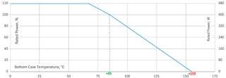
D era ting (thermal r e sis t ) UP T- 4 0 0:
D era ting (thermal r e sis t ) UP T- 4 0 0:
Derating (thermal resist.) UPT®-400:
5 5 5 W/ K (0 18 K / W )
5 5 5 W/ K (0 18 K / W )
5.55 W/K (0.18K/W)
Power rating: 400 W at 85°C bottom case temperature**
Power ra ting: 4 0 0 W a t 8 5° C b ot tom c as e temp era tur e**
Pleas e as k for de t aile d mounting pro c e dur e! R
Power ra ting: 4 0 0 W a t 8 5° C b ot tom c as e temp era tur e** Pleas e as k for de t aile d mounting pro c e dur e!
Please ask for detailed mounting procedure!
** This value is only applicable when using a
be
than 0.05 mm overall. Surface roughness should not exceed 6.4 μm.
Series UPT®-600
600 W resistor, US Patent-No. 5,355,281
For variable speed drives, power supplies, control devices, robotics, motor control and other power designs, the easy mounting fixture guarantees an auto-calibrated pressure to the cooling plate of about 300 N.
Features
multiple resistors in 1 package
Non-Inductive design
ROHS compliant
High insulation & partial discharge performance
Materials in accordance with UL 94 V-0
T hermal interface management available (ask for details)
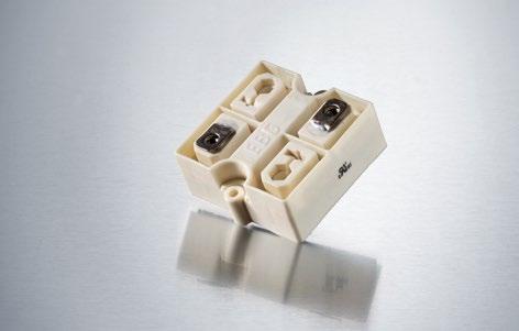
Technical Specifications
Resistance value 0.03 Ω to 1.5 MΩ (higher values on request)
Resistance tolerance ±5 % to ±10 % ±1 % to ±2 % on special request for limited ohmic value with the reduction of the max. power / pulse rating (ask for details)
Temperature coefficient
±500 ppm/°C (0.1 Ω to 0.2 Ω) standard ±150 ppm/°C (> 0.2 Ω to 1.5 MΩ) standard lower TCR on special request for limited ohmic values
Power rating up to 600 W at 85°C bottom case temperature (see configurations)
Short time overload 1000 W at 70°C for 10s., ΔR = 0.4% max. (for configuration 2 and 3)
Operating working voltage 5000 V DC = 3500 V AC RMS (50 Hz) higher voltage on request, not exceeding max. power
Dielectric strength
7 kVrms / 50 Hz / 500 VA, test time 1 min. between terminal und case (up to 12 kVrms on request) voltages above 10 kVrms are tested at DC equivalent to avoid pre damage of component
Dielectric strength between R1-R2 ≤ 5 kV DC (for conf. 4)
Partial discharge
4 kVrms < 10 pC (up to 7 kVrms < 10 pC on request) acc. to IEC 60270
Insulation resistance > 10 GΩ at 1000 V
Single shot voltage up to 12 kV norm wave (1.5/50 μs)
Inductance ≤ 80 nH (typical), measuring frequency 10 kHz
Capacity/mass ≤ 110 pF (typical), measuring frequency 10 kHz
Capacity/parallel ≤ 40 pF (typical), measuring frequency 10 kHz
Operating temperature -55°C to +155°C
Mounting - torque for contacts 1.8 Nm to 2 Nm, screw-in depth max. 6 mm
Mounting - torque 1.6 Nm to 1.8 Nm M4 screws
Contacts standard M5 (M4 on special request)
Terminal tops for additional insulation requirements on special request (ask for details)
General pulse load information
contact our local Miba representative or contact us directly
Weight ~137 g
General Specifications
Housing
Housings are made without color additives. The color definition is natural and can vary in different pigmentation
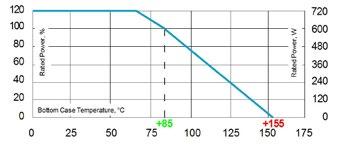
Derating (thermal resist.) UPT®-600: 8.33 W/K (0.12 K/W) for configuration 2 and 3
Power rating: 600 W at 85°C bottom case temperature*
* This value is only applicable when using a thermal conduction to the heat sink Rth-cs<0.025 K/W. This value can be obtained by using a thermal transfer compound with a heat conductivity of at least 1 W/mK. The flatness of the cooling plate must be better than 0.05 mm overall. Surface roughness should not exceed 6.4 μm.
Please note most all of our UPT customers have their own custom designed drawing. Therefore please do not hesitate to discuss your special needs with the local representative or contact us directly.
Borehole Distance
Ultra-High-Power Resistor s
Series UPT-60 0 6 0 0 W resis tor, US Patent- No. 5, 3 55, 281
Dimensions in mm [inches]
How to make a request
UPT-600-Configuration_Ohmic Value_Tolerance
How to make a re q ue s t UP T- 6 0 0 - C on fi gu r a t i on O hmi c Va l u e To l e r a n c e
For example: UPT-600-2 5R 10% or UPT-800-7 3x50K 5%
Configurations (P / package)
Dime ns ions in mm [inc he s] (P / pa c kage) S t a nd a r d ve r s i o n

Series UPT®-800
800 W resistor, US Patent-No. 5,355,281 1/2 Ultra-High-Power
For variable speed drives, power supplies, control devices, robotics, motor control and other power designs, the easy mounting fixture assures an auto-calibrated pressure to the cooling plate of about 300 N.
Features
multiple resistors in 1 package
Non-Inductive design
ROHS compliant
High insulation & partial discharge performance
Materials in accordance with UL 94 V-0
T hermal interface management available (ask for details)
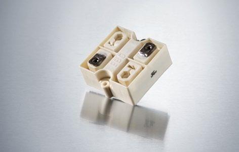
Technical Specifications
Resistance value 0.03 Ω to 1 MΩ (higher values on request)
Resistance tolerance ±5 % to ±10 % ±1 % to ±2 % on special request for limited ohmic values with the reduction of the max. power / pulse rating (ask for details)
Temperature coefficient
±500 ppm/°C (0.1 Ω to 0.2 Ω) standard ±150 ppm/°C (> 0.2 Ω to 1 MΩ) standard lower TCR on special request for limited ohmic values
Power rating up to 800 W at 85°C bottom case temperature (see configurations)
Short time overload 1000 W at 70°C for 10s., ΔR = 0.4% max. (for configuration 2 and 3)
Operating working voltage
Dielectric strength
5000 V DC = 3500 V AC RMS (50 Hz) higher voltage on request, not exceeding max. power
7 kVrms / 50 Hz / 500 VA, test time 1 min. between terminal und case (up to 12 kVrms on request) voltages above 10 kVrms are tested at DC equivalent to avoid pre damage of component
Dielectric strength between R1-R2 ≤ 5 kV DC (for conf. 4)
Partial discharge 4 kVrms < 10 pC (up to 7 kVrms < 10 pC on request) acc. to IEC 60270
Insulation resistance > 10 GΩ at 1000 V
Single shot voltage up to 12 kV norm wave (1.5/50 μs)
Inductance ≤ 80 nH (typical), measuring frequency 10 kHz
Capacity/mass ≤ 140 pF (typical), measuring frequency 10 kHz
Capacity/parallel ≤ 40 pF (typical), measuring frequency 10 kHz
Operating temperature -55°C to +155°C
Mounting - torque for contacts 1.8 Nm to 2 Nm, screw-in depth max. 6 mm
Mounting - torque 1.6 Nm to 1.8 Nm M4 screws
Contacts standard M5 (M4 on special request)
Terminal tops for additional insulation requirements on special request (ask for details)
General pulse load information contact our local Miba representative or contact us directly
Weight ~137 g
General Specifications
Housing
Housings are made without color additives. The color definition is natural and can vary in different pigmentation
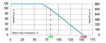
Derating (thermal resist.) UPT®-800: 9.09 W/K (0.11 K/W) for configuration 2 and 3
Power rating: 800 W at 85°C bottom case temperature*
* This value is only applicable when using a thermal conduction to the heat sink Rth-cs<0.025 K/W. This value can be obtained by using a thermal transfer compound with a heat conductivity of at least 1 W/mK. The flatness of the cooling plate must be better than 0.05 mm overall. Surface roughness should not exceed 6.4 μm.
Please note most all of our UPT customers have their own custom designed drawing. Therefore please do not hesitate to discuss your special needs with the local representative or contact us directly.
Borehole Distance
Series UPT®-800
Dimensions in mm [inches]
How to make a request
UPT-800-Configuration_Ohmic Value_Tolerance
For example: UPT-800-2 5R 10% or UPT-800-4 2x1K 5%
Configurations (P / package) Standard version
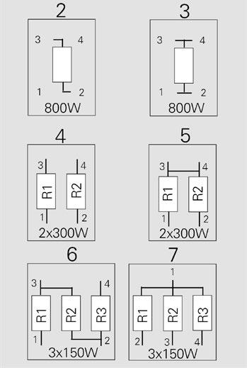
Series UPT®-2000
2000 W resistor, US Patent-No. 5,355,281
For variable speed drives, power supplies, control devices, robotics, motor control and other power designs, the easy mounting fixture assures an auto-calibrated pressure to the cooling plate of about 300 N.
Features
multiple resistors in 1 package
Non-Inductive design
ROHS compliant
High insulation & partial discharge performance
Materials in accordance with UL 94 V-0
T hermal interface management available (ask for details)
Technical Specifications
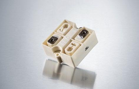
General Specifications
Resistance value 0.1 Ω to 6 KΩ (higher values on request)
Resistance tolerance ±5 % to ±10 %
Temperature coefficient ±250 ppm/°C standard lower TCR on special request for limited ohmic values
Power rating up to 2000 W at 125°C bottom case temperature (see configurations)
Short time overload
Operating working voltage
Dielectric strength
2400 W at 70°C for 10s., ΔR = 0.4% max. (for configuration 2 and 3)
5000 V DC = 3500 V AC RMS (50 Hz) higher voltage on request, not exceeding max. power
7 kVrms / 50 Hz / 500 VA, test time 1 min. between terminal und case (up to 12 kVrms on request) voltages above 10 kVrms are tested at DC equivalent to avoid pre damage of component
Dielectric strength between R1-R2 ≤ 5 kV DC (for conf. 4)
Partial discharge
4 kVrms < 10 pC (up to 7 kVrms < 10 pC on request) acc. to IEC 60270
Insulation resistance > 10 GΩ at 1000 V
Single shot voltage up to 12 kV norm wave (1.5/50 μs)
Inductance ≤ 80 nH (typical), measuring frequency 10 kHz
Capacity/mass ≤ 120 pF (typical), measuring frequency 10 kHz
Capacity/parallel ≤ 40 pF (typical), measuring frequency 10 kHz
Operating temperature -55°C to +155°C
Mounting - torque for contacts 1.8 Nm to 2 Nm, screw-in depth max. 6 mm
Mounting - torque 1.6 Nm to 1.8 Nm M4 screws
Contacts standard M5 (M4 on special request)
Terminal tops for additional insulation requirements on special request (ask for details)
General pulse load information contact our local Miba representative or contact us directly
Weight ~137 g
Housing
Housings are made without color additives. The color definition is natural and can vary in different pigmentation
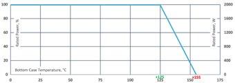
Derating (thermal resist.) UPT®-2000: 66.6 W/K (0.015 K/W) for configuration 2 and 3
Power rating: 2000 W at 125°C bottom case temperature*
* This value is only applicable when using a thermal conduction to the heat sink Rth-cs<0.025 K/W. This value can be obtained by using a thermal transfer compound with a heat conductivity of at least 2.9 W/mK. The flatness of the cooling plate must be better than 0.05 mm overall. Surface roughness should not exceed 6.4 μm.
Please note most all of our UPT customers have their own custom designed drawing. Therefore please do not hesitate to discuss your special needs with the local representative or contact us directly.
Borehole Distance
Series UPT®-2000
Dimensions in mm [inches]
How to make a request
UPT-2000-Configuration_Ohmic Value_Tolerance
For example: UPT-2000-2 5R 10% or UPT-2000-4 2x1K 5%
Configurations (P / package) Standard version
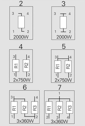
Ultra-High-Power Resistors
Series UPT®-3000
3000 W resistor 1/2
For variable speed drives, power supplies, control devices, robotics, motor control and other power designs, the easy mounting fixture assures an auto-calibrated pressure to the cooling plate of about 300 N.
Features
multiple resistors in 1 package
Non-Inductive design
ROHS compliant
High insulation & partial discharge performance
Materials in accordance with UL 94 V-0
T hermal interface management available (ask for details)
Technical Specifications
Resistance value 0.1 Ω to 6 KΩ (higher values on request)
Resistance tolerance ±5 % to ±10 %
Temperature coefficient ±250 ppm/°C standard
Power rating up to 3000 W at 110°C bottom case temperature (see configurations)
Short time overload 3600 W at 70°C for 10s., ΔR = 0.4% max. (for configuration 2 and 3)
Operating working voltage 5000 V DC = 3500 V AC RMS (50 Hz) higher voltage on request, not exceeding max. power
Dielectric strength
7 kVrms / 50 Hz / 500 VA, test time 1 min. between terminal und case (up to 12 kVrms on request) voltages above 10 kVrms are tested at DC equivalent to avoid pre damage of component
Dielectric strength between R1-R2 ≤ 5 kV DC (for conf. 4)
Partial discharge 4 kVrms < 10 pC (up to 7 kVrms < 10 pC on request) acc. to IEC 60270
Insulation resistance > 10 GΩ at 1000 V
Single shot voltage up to 12 kV norm wave (1.5/50 μs)
Inductance ≤ 80 nH (typical), measuring frequency 10 kHz
Capacity/mass ≤ 120 pF (typical), measuring frequency 10 kHz
Capacity/parallel ≤ 40 pF (typical), measuring frequency 10 kHz
Operating temperature -55°C to +155°C
Mounting - torque for contacts 1.8 Nm to 2 Nm, screw-in depth max. 6 mm
Mounting - torque 1.6 Nm to 1.8 Nm M4 screws
Contacts standard M5 (M4 on special request)
Terminal tops for additional insulation requirements on special request (ask for details)
General pulse load information contact our local Miba representative or contact us directly
Weight ~137 g
General Specifications
Housing
Housings are made without color additives. The color definition is natural and can vary in different pigmentation
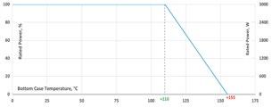
Derating (thermal resist.) UPT®-3000: 66.6 W/K (0.015 K/W) for configuration 2 and 3
Power rating: 3000 W at 110°C bottom case temperature*
* This value is only applicable when using a thermal conduction to the heat sink Rth-cs<0.025 K/W. This value can be obtained by using a thermal transfer compound with a heat conductivity of at least 2.9 W/mK. The flatness of the cooling plate must be better than 0.05 mm overall. Surface roughness should not exceed 6.4 μm.
Please note most all of our UPT customers have their own custom designed drawing. Therefore please do not hesitate to discuss your special needs with the local representative or contact us directly.
Borehole Distance
Series UPT®-3000
Dimensions in mm [inches]
How to make a request
UPT-3000-Configuration_Ohmic Value_Tolerance
For example: UPT-3000-2 5R 10% or UPT-3000-4 2x1K 5%
Configurations (P / package)
Ultra-High-Power Resistors
Series UPT-800
800 W resistor, US Patent-No. 5,355,281
Series ULX®-600
(very low component height)
600 W resistor, US Patent-No. 5,355,281
For variable speed drives, power supplies, control devices, robotics, motor control and other power designs, the easy mounting fixture assures an auto-calibrated pressure to the cooling plate of about 120 to 160 N.
Features
For variable speed drives, power supplies, control devices, robotics, motor control and other power designs.
1x 800 W / 2x 300 W / 3x 150 W operating power
Non-Inductive design
ROHS compliant
High insulation & partial discharge performance
Features
Materials in accordance with UL 94 V-0
multiple resistors in 1 package
Non-Inductive design
Resistor is also available with preapplied PCM (Phase Change Material) (ask for details)
ROHS compliant
High insulation & partial discharge performance
Technical Specifications
Materials in accordance with UL 94 V-0
Resistance value 0.1 Ω ≤ 0.2 Ω (HC-version) > 0.2 Ω ≤ 1 MΩ (higher values on special request)
Resistance tolerance ±10 % to ±5 % ±2 % to ±1 % on special request for limited ohmic values with the reduction of the max. power / pulse rating (ask for details)
Technical Specifications
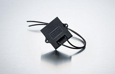
Resistance value 0.03 Ω to 1.5 MΩ (higher values on request)
Temperature coefficient ±500 ppm/°C (0.1 Ω ≤ 0.2 Ω) Standard ±150 ppm/°C (> 0.2 Ω ≤ 1 MΩ) Standard lower TCR on special request for limited ohmic values
Power Rating
T hermal interface management available (ask for details) Borehole
General Specifications
Electric support
Resistance tolerance ±5 % to ±10 % ±1 % to ±2 % on special request for limited ohmic values with the reduction of the max. power / pulse rating (ask for details)
Power rating up to 800 W at 85°C bottom case temperature (see configurations)
Short time overload 1,000 W at 70°C for 10sec., ΔR = 0.4% max. (for configuration 2 and 3)
Temperature coefficient
High-purity ceramic metalized with Miba Resistors ALTOX film on the bottom for better heat transfer and optimum discharge
±500 ppm/°C (0.1 Ω to 0.2 Ω) standard ±150 ppm/°C (> 0.2 Ω to 1.5 MΩ) standard lower TCR on special request for limited ohmic values
Maximum working voltage 5,000 V DC = 3.500 V AC RMS (50 Hz) higher voltage on request, not exceeding max. power
Power rating up to 600 W at 85°C bottom case temperature (see configurations)
Short time overload
Electric strength voltage 7 kVrms / 50 Hz / 500 VA, test time 1 min. (up to 12 kVrms on request) voltages above 10 kVrms are tested at DC equivalent to avoid pre damage of component terminal and case
Operating working voltage
Derating (thermal resist.) UPT-800: 9.09 W/K (0.11 K/W) for configuration 2 and 3
Encapsulation
1000 W at 70°C for 10s., ΔR = 0.4 % max. (for configuration 2 and 3)
Dielectric strength between R1-R2 > 5 kV DC Partial discharge 4 kVrms < 10 pC (up to 7 kVrms < 10 pC on request) acc. to IEC 60270
5000 V DC = 3500 V AC RMS (50 Hz) higher voltage on request, not exceeding max. power
Maximum continuous current 20A for 1.5mm2 for AWG @25°C (not exceeding max. power rating)
Insulation resistance > 10 GΩ at 1.000 V
Dielectric strength
Single shot voltage up to 12 kV norm wave (1.5/50 μsec)
Inductance ≥ 80 nH (typical), measuring frequency 10 kHz
7 kVrms / 50 Hz / 500 VA, test time 1 min between terminal und case (up to 12 kVrms on request) voltages above 10 kVrms are tested at DC equivalent to avoid pre damage of component
Capacity/mass ≥ 140 pF (typical), measuring frequency 10 kHz
Partial discharge
Capacity/parallel ≥ 40 pF (typical), measuring frequency 10 kHz
4 kVrms < 10 pC (up to 7 kVrms < 10 pC on request) acc. to IEC 60270
Operating temperature -55°C to +155°C
Mounting - max. torque for contacts 2 Nm
Peak current up to 1500 A depending on pulse length and frequency (ask for details)
Insulation resistance > 10 G at 1000 V
Mounting - max. torque 1.8 Nm M4 screws
Single shot voltage up to 12 kV norm wave (1.5/50 μs)
Contacts standard M5 (M4 on special request)
Terminal tops for additional insulation requirements & cable variation on special request (ask for details)
Inductance ≤ 80 nH (typical), measuring frequency 10 kHz
Capacity/mass ≤ 110 pF (typical), measuring frequency 10 kHz
Capacity/parallel ≤ 40 pF (typical), measuring frequency 10 kHz
Cable variation on special request (ask for details)
Operating temperature res. body: -55°C to +155°C std. cables: -40°C to +120°C (other cables upon request)
Standard cable type H&S Radox 9 GKW AX 1,5mm² (other cable types on special request)
General pulse load information contact our local EBG representative or contact us directly
Mounting - torque 1.6 Nm to 1.8 Nm M4 screws
Weight ~137 g
Standard cable length 250 mm (other cable lengths on special request)
Standard cable type H&S Radox 9 GKW AX 1,5 mm2 (other cable types on special request)
General Pulse Load information contact our local Miba representative or contact us directly
Weight ~92 g depending on cable
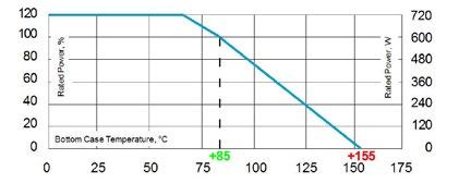
Power rating: 800 W at 85°C bottom case temperature* Please ask for detailed mounting procedure!
Resin-filled epoxy casing. High insulation resistance (CTI 600), high dielectric strength and partial discharge capability
Resistance Element
Special design for low inductance and capacitance values. The element employs our special METOXFILM, which demonstrates stability while covering high wattage and pulse loading
Please note most all of our UPT customers have their own custom designed drawing. Therefore please do not hesitate to discuss your special needs with the local representative or contact us directly.
Derating (thermal resist.) ULX®-600: 8.33 W/K (0.12K/W)
Power rating: 600 W at 85°C bottom case temperature*
Please ask for detailed mounting procedure!
* This value is only applicable when using a thermal conduction to the heat
μm.
Borehole Distance
Series ULX®-600
Test Specifications*
* The test methods are according to IEC 60068-2 ** The tolerance drift is the possible change of the resistance value because of the certain test
Configurations
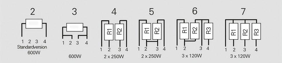
How to make a request
ULX-600-Configuration_Ohmic Value_Tolerance
For example:
ULX-600-2 620R 10% or ULX-600-4 2x15K 5%
als Typenbezeichnung
Dimensions in mm [inches]
Ultra-High-Power Resistors
Ultra-High-Power Resistors
Series UPT-800
800 W resistor, US Patent-No. 5,355,281
Series ULX®-800
800 W resistor
(very low component height)
For variable speed drives, power supplies, control devices, robotics, motor control and other power designs, the easy mounting fixture assures an auto-calibrated pressure to the cooling plate of about 120 to 160 N.
Features
1x 800 W / 2x 300 W / 3x 150 W operating power
For variable speed drives, power supplies, control devices, robotics, motor control and other power designs.
Non-Inductive design
ROHS compliant
High insulation & partial discharge performance
Features
Materials in accordance with UL 94 V-0
multiple resistors in 1 package
Non-Inductive design
Resistor is also available with preapplied PCM (Phase Change Material) (ask for details)
ROHS compliant
High insulation & partial discharge performance
Technical Specifications
Materials in accordance with UL 94 V-0
T hermal interface management available (ask for details)
Resistance value 0.1 Ω ≤ 0.2 Ω (HC-version) > 0.2 Ω ≤ 1 MΩ (higher values on special request)
Resistance tolerance ±10 % to ±5 % ±2 % to ±1 % on special request for limited ohmic values with the reduction of the max. power / pulse rating (ask for details)
Technical Specifications
Power Rating
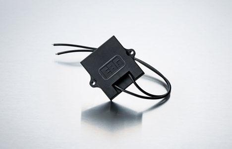
Temperature coefficient ±500 ppm/°C (0.1 Ω ≤ 0.2 Ω) Standard ±150 ppm/°C (> 0.2 Ω ≤ 1 MΩ) Standard lower TCR on special request for limited ohmic values
Resistance value 0.03 Ω to 1 MΩ (higher values on request)
General Specifications
Electric support
Power rating up to 800 W at 85°C bottom case temperature (see configurations)
Resistance tolerance ±5 % to ±10 % ±1 % to ±2 % on special request for limited ohmic values with the reduction of the max. power / pulse rating (ask for details)
Short time overload 1,000 W at 70°C for 10sec., ΔR = 0.4% max. (for configuration 2 and 3)
Temperature coefficient
Maximum working voltage 5,000 V DC = 3.500 V AC RMS (50 Hz) higher voltage on request, not exceeding max. power
±500 ppm/°C (0.1 Ω to 0.2 Ω) standard ±150 ppm/°C (> 0.2 Ω to 1 MΩ) standard lower TCR on special request for limited ohmic values
Power rating up to 800 W at 85°C bottom case temperature (see configurations)
Electric strength voltage 7 kVrms / 50 Hz / 500 VA, test time 1 min. (up to 12 kVrms on request) voltages above 10 kVrms are tested at DC equivalent to avoid pre damage of component terminal and case
Short time overload 1000 W at 70°C for 10s., ΔR = 0.4 % max. (for configuration 2 and 3)
High-purity ceramic metalized with Miba Resistors ALTOX film on the bottom for better heat transfer and optimum discharge
Derating (thermal resist.) UPT-800: 9.09 W/K (0.11 K/W) for configuration 2 and 3
Encapsulation
Power rating: 800 W at 85°C bottom case temperature* Please ask for detailed mounting procedure!
Resin-filled epoxy casing. High insulation resistance (CTI 60 0), high dielectric strength and partial discharge capability
Operating working voltage
Dielectric strength between R1-R2 > 5 kV DC
5000 V DC = 3500 V AC RMS (50 Hz) higher voltage on request, not exceeding max. power
Resistance Element
Partial discharge 4 kVrms < 10 pC (up to 7 kVrms < 10 pC on request) acc. to IEC 60270
Maximum continuous current 20A for 1.5mm2 for AWG @25°C (not exceeding max. power rating)
Insulation resistance > 10 GΩ at 1.000 V
Single shot voltage up to 12 kV norm wave (1.5/50 μsec)
Dielectric strength
Inductance ≥ 80 nH (typical), measuring frequency 10 kHz
7 kVrms / 50 Hz / 500 VA, test time 1 min. between terminal und case (up to 12 kVrms on request) voltages above 10 kVrms are tested at DC equivalent to avoid pre damage of component
Special design for low inductance and capacitance values. The element employs our special METOXFILM, which demonstrates stability while covering high wattage and pulse loading
Partial discharge
Capacity/mass ≥ 140 pF (typical), measuring frequency 10 kHz
Capacity/parallel ≥ 40 pF (typical), measuring frequency 10 kHz
4 kVrms < 10 pC (up to 7 kVrms < 10 pC on request) acc. to IEC 60270
Operating temperature -55°C to +155°C
Mounting - max. torque for contacts 2 Nm
Peak current up to 1500 A depending on pulse length and frequency (ask for details)
Insulation resistance > 10 G at 1000 V
Mounting - max. torque 1.8 Nm M4 screws
Single shot voltage up to 12 kV norm wave (1.5/50 μs)
Contacts standard M5 (M4 on special request)
Terminal tops for additional insulation requirements & cable variation on special request (ask for details)
Inductance ≤ 80 nH (typical), measuring frequency 10 kHz
Capacity/mass ≤ 140 pF (typical), measuring frequency 10 kHz
Cable variation on special request (ask for details)
Capacity/parallel ≤ 40 pF (typical), measuring frequency 10 kHz
Operating temperature res. body: -55°C to +155°C std. cables: -40°C to +120°C (other cables upon request)
Standard cable type H&S Radox 9 GKW AX 1,5mm² (other cable types on special request)
General pulse load information contact our local EBG representative or contact us directly
Mounting - torque 1.6 Nm to 1.8 Nm M4 screws
Weight ~137 g
Standard cable length 250 mm (other cable lengths on special request)
Standard cable type H&S Radox 9 GKW AX 1,5 mm2 (other cable types on special request)
General Pulse Load information contact our local Miba representative or contact us directly
Weight ~92 g depending on cable
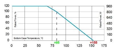
Please note most all of our UPT customers have their own custom designed drawing. Therefore please do not hesitate to discuss your special needs with the local representative or contact us directly.
Derating (thermal resist.) ULX®-800: 9.09 W/K (0.11K/W) for configuration 2 und 3
Power rating: 800 W at 85°C bottom case temperature*
Please ask for detailed mounting procedure!
Borehole Distance
Series ULX®-800
Test Specifications* Test
* The test methods are according to IEC 60068-2 ** The tolerance drift is the possible change of the resistance value because of the certain test
How to make a request
ULX-800-Configuration_Ohmic Value_Tolerance
For example:
3K 5% or ULX-800-4 2x15K 5% Configurations
als Typenbezeichnung
Dimensions in mm [inches]
Ultra-High-Power Resistors
Series UPT-800
Ultra-High-Power Resistors
800 W resistor, US Patent-No. 5,355,281
Series ULX®-2000
2000 W resistor at 125°C bottom case
For variable speed drives, power supplies, control devices, robotics, motor control and other power designs, the easy mounting fixture assures an auto-calibrated pressure to the cooling plate of about 120 to 160 N.
Features
1x 800 W / 2x 300 W / 3x 150 W operating power
(very low component height)
For variable speed drives, power supplies, control devices, robotics, motor control and other power designs.
Non-Inductive design
ROHS compliant
High insulation & partial discharge performance
Materials in accordance with UL 94 V-0
Features
Resistor is also available with preapplied PCM (Phase Change Material) (ask for details)
multiple resistors in 1 package
Non-Inductive design
ROHS compliant
Technical Specifications
High insulation & partial discharge performance
Materials in accordance with UL 94 V-0
T hermal interface management available (ask for details)
Resistance value 0.1 Ω ≤ 0.2 Ω (HC-version) > 0.2 Ω ≤ 1 MΩ (higher values on special request)
Resistance tolerance ±10 % to ±5 % ±2 % to ±1 % on special request for limited ohmic values with the reduction of the max. power / pulse rating (ask for details)
Technical Specifications
Power Rating
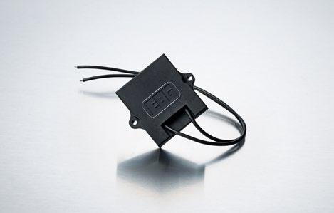
Temperature coefficient ±500 ppm/°C (0.1 Ω ≤ 0.2 Ω) Standard ±150 ppm/°C (> 0.2 Ω ≤ 1 MΩ) Standard lower TCR on special request for limited ohmic values
Resistance value 0.1 Ω to 6 KΩ
Resistance tolerance ±5 % to ±10 %
Power rating up to 800 W at 85°C bottom case temperature (see configurations)
General Specifications
Electric support
Short time overload 1,000 W at 70°C for 10sec., ΔR = 0.4% max. (for configuration 2 and 3)
Temperature coefficient ±250 ppm/°C standard lower TCR on special request for limited ohmic values
Maximum working voltage 5,000 V DC = 3.500 V AC RMS (50 Hz) higher voltage on request, not exceeding max. power
Power rating up to 2000 W at 125°C bottom case temperature (see configurations)
Short time overload 2400 W at 70°C for 10s., ΔR = 0.4% max. (see configurations)
Operating working voltage 5000 V DC = 3500 V AC RMS (50 Hz) higher voltage on request, not exceeding max. power
Electric strength voltage 7 kVrms / 50 Hz / 500 VA, test time 1 min. (up to 12 kVrms on request) voltages above 10 kVrms are tested at DC equivalent to avoid pre damage of component terminal and case
Dielectric strength between R1-R2 > 5 kV DC
Maximum continuous current 20A for 1.5mm2 for AWG @25°C (not exceeding max. power rating)
Partial discharge 4 kVrms < 10 pC (up to 7 kVrms < 10 pC on request) acc. to IEC 60270
Dielectric strength
Insulation resistance > 10 GΩ at 1.000 V
7 kVrms / 50 Hz / 500 VA, test time 1 min. between terminal und case (up to 12 kVrms on request) voltages above 10 kVrms are tested at DC equivalent to avoid pre damage of component
Single shot voltage up to 12 kV norm wave (1.5/50 μsec)
Partial discharge
High-purity ceramic metalized with Miba Resistors ALTOX film on the bottom for better heat transfer and optimum discharge
Derating (thermal resist.) UPT-800: 9.09 W/K (0.11 K/W) for configuration 2 and 3
Encapsulation
Power rating: 800 W at 85°C bottom case temperature* Please ask for detailed mounting procedure!
Resin-filled epoxy casing. High insulation resistance (CTI 60 0), high dielectric strength and partial discharge capability
Resistance Element
4 kVrms < 10 pC (up to 7 kVrms < 10 pC on request) acc. to IEC 60270
Inductance ≥ 80 nH (typical), measuring frequency 10 kHz
Capacity/mass ≥ 140 pF (typical), measuring frequency 10 kHz
Capacity/parallel ≥ 40 pF (typical), measuring frequency 10 kHz
Peak current up to 1500 A depending on pulse length and frequency (ask for details)
Operating temperature -55°C to +155°C
Insulation resistance > 10 G at 1000 V
Mounting - max. torque for contacts 2 Nm
Single shot voltage up to 12 kV norm wave (1.5/50 μs)
Mounting - max. torque 1.8 Nm M4 screws
Inductance ≤ 80 nH (typical), measuring frequency 10 kHz
Contacts standard M5 (M4 on special request)
Capacity/mass ≤ 140 pF (typical), measuring frequency 10 kHz
Terminal tops for additional insulation requirements & cable variation on special request (ask for details)
Capacity/parallel ≤ 40 pF (typical), measuring frequency 10 kHz
Operating temperature res. body: -55°C to +155°C std. cables: -40°C to +120°C (other cables upon request)
Cable variation on special request (ask for details)
Standard cable type H&S Radox 9 GKW AX 1,5mm² (other cable types on special request)
Mounting - torque 1.6 Nm to 1.8 Nm M4 screws
Standard cable length 250 mm (other cable lengths on special request)
General pulse load information contact our local EBG representative or contact us directly
Standard cable type
Weight ~137 g
H&S Radox 9 GKW AX 1,5 mm2 (other cable types on special request)
General Pulse Load information contact our local Miba representative or contact us directly
Weight ~92 g depending on cable
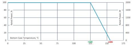
2 and 3
Please note most all of our UPT customers have their own custom designed drawing. Therefore please do not hesitate to discuss your special needs with the local representative or contact us directly.
Special design for low inductance and capacitance values. The element employs our special METOXFILM, which demonstrates stability while covering high wattage and pulse loading
Borehole Distance
Derating (thermal resist.) ULX®-2000: 66.6 W/K (0.015 K/W) for confirguration
Power rating: 2000 W at 125°C bottom case temperature*
Please ask for detailed mounting procedure!
Borehole Distance
Series ULX®-2000
Test Specifications*
Test
* The test methods are according to IEC 60068-2
** The tolerance drift is the possible change of the resistance value because of the certain test
Configurations
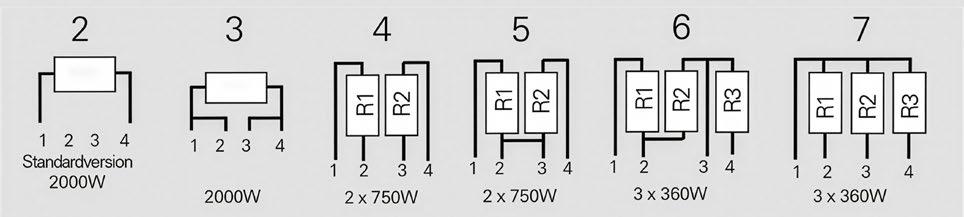
How to make a request
ULX-2000-Configuration_Ohmic Value_Tolerance
For example:
Dimensions in mm [inches]
Ultra-High-Power Resistors
Series UPT-800
Series UNX-600
800 W resistor, US Patent-No. 5,355,281
(very low component height)
600 W resistor, sandwitch construction upgrade model for our ULX-600 series
For variable speed drives, power supplies, control devices, robotics, motor control and other power designs, the easy mounting fixture assures an auto-calibrated pressure to the cooling plate of about 120 to 160 N.
Features
For variable speed drives, power supplies, control devices, robotics, motor control and other power designs.
1x 800 W / 2x 300 W / 3x 150 W operating power
Non-Inductive design
ROHS compliant
High insulation & partial discharge performance
Features
Materials in accordance with UL 94 V-0
multiple resistors in 1 package
Non-Inductive design
Resistor is also available with preapplied PCM (Phase Change Material) (ask for details)
ROHS compliant
High insulation & partial discharge performance
Technical Specifications
Materials in accordance with UL 94 V-0
Resistance value 0.1 Ω ≤ 0.2 Ω (HC-version) > 0.2 Ω ≤ 1 MΩ (higher values on special request)
Resistance tolerance ±10 % to ±5 % ±2 % to ±1 % on special request for limited ohmic values with the reduction of the max. power / pulse rating (ask for details)
Technical Specification
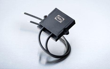
Resistance value 0.03 Ω to 1.5 MΩ (higher values on request)
Temperature coefficient ±500 ppm/°C (0.1 Ω ≤ 0.2 Ω) Standard ±150 ppm/°C (> 0.2 Ω ≤ 1 MΩ) Standard lower TCR on special request for limited ohmic values
Power Rating
T hermal interface management available (ask for details) Borehole Distance
General Specifications
Electric support
Power rating up to 800 W at 85°C bottom case temperature (see configurations)
Resistance tolerance ±5 % to ±10 % ±1 % to ±2 % on special request with the reduction of the max. power / pulse rating (ask for details)
Temperature coefficient
Short time overload 1,000 W at 70°C for 10sec., ΔR = 0.4% max. (for configuration 2 and 3)
±500 ppm/°C (0.1 Ω to 0.2 Ω) standard ±150 ppm/°C (> 0.2 Ω to 1.5 MΩ) standard lower TCR on special request for limited ohmic values
Maximum working voltage 5,000 V DC = 3.500 V AC RMS (50 Hz) higher voltage on request, not exceeding max. power
Power rating up to 600 W at 85°C bottom case temperature (see configurations)
Electric strength voltage 7 kVrms / 50 Hz / 500 VA, test time 1 min. (up to 12 kVrms on request) voltages above 10 kVrms are tested at DC equivalent to avoid pre damage of component terminal and case
Short time overload 1000 W at 70°C for 10s., ΔR = 0.4 % max. (for configuration 2 and 3)
Operating working voltage
5000 V DC = 3500 V AC RMS (50 Hz) higher voltage on request, not exceeding max. power
Dielectric strength between R1-R2 > 5 kV DC
High-purity ceramic metalized with Miba Resistors ALTOX film on the bottom for better heat transfer and optimum discharge
Derating (thermal resist.) UPT-800: 9.09 W/K (0.11 K/W) for configuration 2 and 3
Encapsulation
Power rating: 800 W at 85°C bottom case temperature* Please ask for detailed mounting procedure!
Resin-filled epoxy casing. High insulation resistance (CTI 60 0), high dielectric strength and partial discharge capability
Resistance Element
Partial discharge 4 kVrms < 10 pC (up to 7 kVrms < 10 pC on request) acc. to IEC 60270
Maximum continuous current 20A for 1.5mm2 for AWG @25°C (not exceeding max. power rating)
Insulation resistance > 10 GΩ at 1.000 V
Dielectric strength
Single shot voltage up to 12 kV norm wave (1.5/50 μsec)
7 kVrms / 50 Hz / 500 VA, test time 1 min between terminal und case (up to 12 kVrms on request) voltages above 10 kVrms are tested at DC equivalent to avoid pre damage of component
Inductance ≥ 80 nH (typical), measuring frequency 10 kHz
Partial discharge
Capacity/mass ≥ 140 pF (typical), measuring frequency 10 kHz
4 kVrms < 10 pC (up to 7 kVrms < 10 pC on request) acc. to IEC 60270
Capacity/parallel ≥ 40 pF (typical), measuring frequency 10 kHz
Operating temperature -55°C to +155°C
Peak current up to 1500 A depending on pulse length and frequency (ask for details)
Mounting - max. torque for contacts 2 Nm
Insulation resistance > 10 G at 1000 V
Mounting - max. torque 1.8 Nm M4 screws
Single shot voltage up to 12 kV norm wave (1.5/50 μs)
Contacts standard M5 (M4 on special request)
Inductance ≤ 80 nH (typical), measuring frequency 10 kHz
Terminal tops for additional insulation requirements & cable variation on special request (ask for details)
Capacity/mass ≤ 110 pF (typical), measuring frequency 10 kHz
Capacity/parallel ≤ 40 pF (typical), measuring frequency 10 kHz
Cable variation on special request (ask for details)
Operating temperature res. body: -55°C to +155°C std. cables: -40°C to +120°C (other cables upon request)
Standard cable type H&S Radox 9 GKW AX 1,5mm² (other cable types on special request)
Mounting - torque 1.6 Nm to 1.8 Nm M4 screws
General pulse load information contact our local EBG representative or contact us directly
Standard cable length 250 mm (other cable lengths on special request)
Weight ~137 g
Standard cable type H&S Radox 9 GKW AX 1,5 mm2 (other cable types on special request)
General Pulse Load information contact our local Miba representative or contact us directly
Weight ~100 g depending on cable
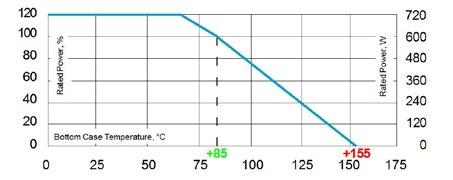
Special design for low inductance and capacitance values. The element employs our special METOXFILM, which demonstrates stability while covering high wattage and pulse loading
Please note most all of our UPT customers have their own custom designed drawing. Therefore please do not hesitate to discuss your special needs with the local representative or contact us directly.
Derating (thermal resist.) UNX-600: 8.33 W/K (0.12K/W) for configuration 2 and 3
Power rating: 600 W at 85°C bottom case temperature*
Please ask for detailed mounting procedure!
* This value is only applicable when using a thermal conduction to the heat
Rth-cs<0.025 K/W. This value can be obtained by using a thermal transfer compound with a heat conductivity of at least 2 W/mK. The flatness of the cooling plate must be better than 0.05 mm overall. Surface roughness should not exceed 6.4 μm.
Borehole Distance
Ultra-High-Power Resistors
Series UNX-600
Test Specifications* Test
* The test methods are according to IEC 60068-2 ** The tolerance drift is the possible change of the resistance value because of the certain test
Configurations
How to make a request
UNX-600-Configuration_Ohmic Value_Tolerance
For example:
UNX-600-2 620R 10% or UNX-600-4 2x15K 5%
Skizze für Katalog
Dimensions in mm [inches]
Ultra-High-Power Resistors
Series UPT-800
Series UNX-800
800 W resistor, US Patent-No. 5,355,281
(very low component height)
800 W resistor, sandwitch construction upgrade model for our ULX-800 series
For variable speed drives, power supplies, control devices, robotics, motor control and other power designs, the easy mounting fixture assures an auto-calibrated pressure to the cooling plate of about 120 to 160 N.
Features
For variable speed drives, power supplies, control devices, robotics, motor control and other power designs.
1x 800 W / 2x 300 W / 3x 150 W operating power
Non-Inductive design
ROHS compliant
High insulation & partial discharge performance
Features
Materials in accordance with UL 94 V-0
multiple resistors in 1 package
Non-Inductive design
Resistor is also available with preapplied PCM (Phase Change Material) (ask for details)
ROHS compliant
High insulation & partial discharge performance
Technical Specifications
Materials in accordance with UL 94 V-0
T hermal interface management available (ask for details)
Resistance value 0.1 Ω ≤ 0.2 Ω (HC-version) > 0.2 Ω ≤ 1 MΩ (higher values on special request)
Resistance tolerance ±10 % to ±5 % ±2 % to ±1 % on special request for limited ohmic values with the reduction of the max. power / pulse rating (ask for details)
Technical Specifications
Temperature coefficient ±500 ppm/°C (0.1 Ω ≤ 0.2 Ω) Standard ±150 ppm/°C (> 0.2 Ω ≤ 1 MΩ) Standard lower TCR on special request for limited ohmic values
Resistance value 0.03 Ω to 1 MΩ (higher values on request)
General Specifications
Electric support
Power rating up to 800 W at 85°C bottom case temperature (see configurations)
Resistance tolerance ±5 % to ±10 % ±1 % to ±2 % on special request with the reduction of the max. power / pulse rating (ask for details)
Temperature coefficient
Short time overload 1,000 W at 70°C for 10sec., ΔR = 0.4% max. (for configuration 2 and 3)
±500 ppm/°C (0.1 Ω to 0.2 Ω) standard ±150 ppm/°C (> 0.2 Ω to 1 MΩ) standard lower TCR on special request for limited ohmic values
Maximum working voltage 5,000 V DC = 3.500 V AC RMS (50 Hz) higher voltage on request, not exceeding max. power
Power rating up to 800 W at 85°C bottom case temperature (see configurations)
Electric strength voltage 7 kVrms / 50 Hz / 500 VA, test time 1 min. (up to 12 kVrms on request) voltages above 10 kVrms are tested at DC equivalent to avoid pre damage of component terminal and case
Short time overload 1000 W at 70°C for 10s., ΔR = 0.4 % max. (for configuration 2 and 3)
Operating working voltage
5000 V DC = 3500 V AC RMS (50 Hz) higher voltage on request, not exceeding max. power
Dielectric strength between R1-R2 > 5 kV DC
Maximum continuous current 20A for 1.5mm2 for AWG @25°C (not exceeding max. power rating)
Partial discharge 4 kVrms < 10 pC (up to 7 kVrms < 10 pC on request) acc. to IEC 60270
Insulation resistance > 10 GΩ at 1.000 V
Dielectric strength
Single shot voltage up to 12 kV norm wave (1.5/50 μsec)
7 kVrms / 50 Hz / 500 VA, test time 1 min. between terminal und case (up to 12 kVrms on request) voltages above 10 kVrms are tested at DC equivalent to avoid pre damage of component
Inductance ≥ 80 nH (typical), measuring frequency 10 kHz
Partial discharge
High-purity ceramic metalized with Miba Resistors ALTOX film on the bottom for better heat transfer and optimum discharge
Derating (thermal resist.) UPT-800: 9.09 W/K (0.11 K/W) for configuration 2 and 3
Encapsulation
Power rating: 800 W at 85°C bottom case temperature* Please ask for detailed mounting procedure!
Resin-filled epoxy casing. High insulation resistance (CTI 60 0), high dielectric strength and partial discharge capability
Resistance Element
Special design for low inductance and capacitance values. The element employs our special METOXFILM, which demonstrates stability while covering high wattage and pulse loading
Capacity/mass ≥ 140 pF (typical), measuring frequency 10 kHz
4 kVrms < 10 pC (up to 7 kVrms < 10 pC on request) acc. to IEC 60270
Capacity/parallel ≥ 40 pF (typical), measuring frequency 10 kHz
Operating temperature -55°C to +155°C
Peak current up to 1500 A depending on pulse length and frequency (ask for details)
Mounting - max. torque for contacts 2 Nm
Insulation resistance > 10 G at 1000 V
Mounting - max. torque 1.8 Nm M4 screws
Single shot voltage up to 12 kV norm wave (1.5/50 μs)
Please note most all of our UPT customers have their own custom designed drawing. Therefore please do not hesitate to discuss your special needs with the local representative or contact us directly.
Borehole Distance
Borehole Distance
Inductance ≤ 80 nH (typical), measuring frequency 10 kHz
Contacts standard M5 (M4 on special request)
Terminal tops for additional insulation requirements & cable variation on special request (ask for details)
Capacity/mass ≤ 140 pF (typical), measuring frequency 10 kHz
Capacity/parallel ≤ 40 pF (typical), measuring frequency 10 kHz
Cable variation on special request (ask for details)
Operating temperature res. body: -55°C to +155°C std. cables: -40°C to +120°C (other cables upon request)
Standard cable type H&S Radox 9 GKW AX 1,5mm² (other cable types on special request)
Mounting - torque 1.6 Nm to 1.8 Nm M4 screws
General pulse load information contact our local EBG representative or contact us directly
Standard cable length 250 mm (other cable lengths on special request)
Weight ~137 g
Standard cable type H&S Radox 9 GKW AX 1,5 mm2 (other cable types on special request)
General Pulse Load information contact our local Miba representative or contact us directly
Weight ~100 g depending on cable
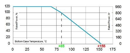
Derating (thermal resist.) UNX-800: 9.09 W/K (0.11K/W) for configuration 2 and 3
Power rating: 800 W at 85°C bottom case temperature*
The above spec. sheet features our standard products. For further options please contact our local EBG representative or contact us directly. sales@ebg-resistors.com · sales@ebg-us.com · szebg@ebg-com.cn Page 1 of 2
Please ask for detailed mounting procedure!
* This value is only applicable when using a thermal conduction to the heat sink Rth-cs<0.025 K/W. This value can be obtained by using a thermal transfer compound with a heat conductivity of at least 2 W/mK. The flatness of the cooling plate must be better than 0.05 mm overall. Surface roughness should not exceed 6.4 μm.
Series UNX-800
Test Specifications* Test
* The test methods are according to IEC 60068-2
** The tolerance drift is the possible change of the resistance value because of the certain test
How to make a request
UNX-800-Configuration_Ohmic Value_Tolerance
Dimensions in mm [inches]
Ultra-High-Power Resistors
Series UPT-800
800 W resistor, US Patent-No. 5,355,281
Series UNC-2000
For variable speed drives, power supplies, control devices, robotics, motor control and other power designs, the easy mounting fixture assures an auto-calibrated pressure to the cooling plate of about 120 to 160 N.
(very low component height)
2000 W resistor at 125°C bottom case upgrade model for our ULX-2000 series
Features
1x 800 W / 2x 300 W / 3x 150 W operating power
Non-Inductive design
For variable speed drives, power supplies, control devices, robotics, motor control and other power designs.
ROHS compliant
High insulation & partial discharge performance
Materials in accordance with UL 94 V-0
Features
multiple resistors in 1 package
Resistor is also available with preapplied PCM (Phase Change Material) (ask for details)
Non-Inductive design
ROHS compliant
Technical Specifications
High insulation & partial discharge performance
Materials in accordance with UL 94 V-0
Resistance value 0.1 Ω ≤ 0.2 Ω (HC-version) > 0.2 Ω ≤ 1 MΩ (higher values on special request)
T hermal interface management available (ask for details)
Resistance tolerance ±10 % to ±5 % ±2 % to ±1 % on special request for limited ohmic values with the reduction of the max. power rating (ask for details)
Technical Specifications
Temperature coefficient ±500 ppm/°C (0.1 Ω ≤ 0.2 Ω) Standard ±150 ppm/°C (> 0.2 Ω ≤ 1 MΩ) Standard lower TCR on special request for limited ohmic values
Resistance value 0.1 Ω to 6 KΩ
Resistance tolerance ±5 % to ±10 %
Power rating up to 800 W at 85°C bottom case temperature (see configurations)
General Specifications
Electric support
Temperature coefficient ±250 ppm/°C standard lower TCR on special request for limited ohmic values
Short time overload 1,000 W at 70°C for 10sec., ΔR = 0.4% max. (for configuration 2 and 3)
Power rating up to 2000 W at 125°C bottom case temperature (see configurations)
Maximum working voltage 5,000 V DC = 3.500 V AC RMS (50 Hz) higher voltage on request, not exceeding max. power
Short time overload
Operating working voltage
2400 W at 70°C for 10s., ΔR = 0.4% max. (see configurations)
Electric strength voltage 7 kVrms / 50 Hz / 500 VA, test time 1 min. (up to 12 kVrms on request) voltages above 10 kVrms are tested at DC equivalent to avoid pre damage of component terminal and case
5000 V DC = 3500 V AC RMS (50 Hz) higher voltage on request, not exceeding max. power
Dielectric strength between R1-R2 > 5 kV DC
Maximum continuous current 20A for 1.5mm2 for AWG @25°C (not exceeding max. power rating)
Partial discharge 4 kVrms < 10 pC (up to 7 kVrms < 10 pC on request) acc. to IEC 60270
Dielectric strength
Insulation resistance > 10 GΩ at 1.000 V
7 kVrms / 50 Hz / 500 VA, test time 1 min. between terminal und case (up to 12 kVrms on request) voltages above 10 kVrms are tested at DC equivalent to avoid pre damage of component
Single shot voltage up to 12 kV norm wave (1.5/50 μsec)
Partial discharge
Inductance ≥ 80 nH (typical), measuring frequency 10 kHz
4 kVrms < 10 pC (up to 7 kVrms < 10 pC on request) acc. to IEC 60270
Capacity/mass ≥ 140 pF (typical), measuring frequency 10 kHz
Capacity/parallel ≥ 40 pF (typical), measuring frequency 10 kHz
Peak current up to 1500 A depending on pulse length and frequency (ask for details)
Operating temperature -55°C to +155°C
Insulation resistance > 10 G at 1000 V
Mounting - max. torque for contacts 2 Nm
Single shot voltage up to 12 kV norm wave (1.5/50 μs)
Mounting - max. torque 1.8 Nm M4 screws
Inductance ≤ 80 nH (typical), measuring frequency 10 kHz
Contacts standard M5 (M4 on special request)
Capacity/mass ≤ 140 pF (typical), measuring frequency 10 kHz
Terminal tops for additional insulation requirements & cable variation on special request (ask for details)
Capacity/parallel ≤ 40 pF (typical), measuring frequency 10 kHz
Operating temperature res. body: -55°C to +155°C std. cables: -40°C to +120°C (other cables upon request)
Cable variation on special request (ask for details)
Standard cable type H&S Radox 9 GKW AX 1,5mm² (other cable types on special request)
Mounting - torque 1.6 Nm to 1.8 Nm M4 screws
Standard cable length 250 mm (other cable lengths on special request)
General pulse load information contact our local EBG representative or contact us directly
Standard cable type H&S Radox 9 GKW AX 1,5 mm2 (other cable types on special request)
Weight ~137 g
General Pulse Load information contact our local Miba representative or contact us directly
Weight ~90 g depending on cable
High-purity ceramic metalized with Miba Resistors ALTOX film on the bottom for better heat transfer and optimum discharge
Derating (thermal resist.) UPT-800: 9.09 W/K (0.11 K/W) for configuration 2 and 3
Encapsulation
Power rating: 800 W at 85°C bottom case temperature* Please ask for detailed mounting procedure!
Resin-filled epoxy casing. High insulation resistance (CTI 60 0), high dielectric strength and partial discharge capability
by
Resistance Element
Special design for low inductance and capacitance values. The element employs our special METOXFILM, which demonstrates stability while covering high wattage and pulse loading
Please note most all of our UPT customers have their own custom designed drawing. Therefore please do not hesitate to discuss your special needs with the local representative or contact us directly.
Borehole Distance
Borehole Distance
Derating (thermal resist.) UNC-2000: 66.6 W/K (0.015 K/W) for confirguration 2 and 3
Power rating: 2000 W at 125°C bottom case temperature*
The above spec. sheet features our standard products. For further options please contact our local EBG representative or contact us directly. sales@ebg-resistors.com · sales@ebg-us.com · szebg@ebg-com.cn Page 1 of 2
Please ask for detailed mounting procedure!
* This value is only applicable when using a thermal conduction to the
Rth-cs<0.025 K/W. This value can be obtained by using a thermal transfer compound with a
2.9
The
Series UNC-2000
Test Specifications*
Test
* The test methods are according to IEC 60068-2
** The tolerance drift is the possible change of the resistance value because of the certain test
Configurations
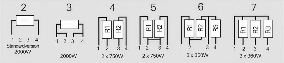
How to make a request
UNC-2000-Configuration_Ohmic Value_Tolerance
For example:
3K 5%
UNX-UNC Skizze für Katalog
Dimensions in mm [inches]
Series UXM-400
400 W resistor, High Pulse Load Resistor
For variable speed drives, power supplies, control devices, robotics, motor control and other power designs, the easy mounting fixture assures an auto-calibrated pressure to the cooling plate of about 300 N.
Features
400 W operating power
Non-Inductive design
ROHS compliant
High insulation & partial discharge performance
Materials in accordance with UL 94 V-0
T hermal interface management available (ask for details)
Technical Specifications
Resistance value 0.1 Ω to 10 Ω
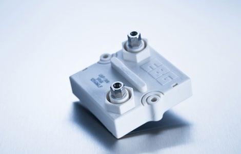
General Specifications
Electric support
Resistance tolerance ±5 % to ±10 % tighter tolerances on special request for limited ohmic values with the reduction of the max. power / pulse rating (ask for details)
Temperature coefficient ±500 ppm/°C typical lower TCR on special request for limited ohmic values
Power rating 400 W at 85°C bottom case temperature
Short time overload 600 W at 70°C for 10s., ΔR = 0.4% max.
Operating working voltage depending on max. pulse load capability (ask for details)
Dielectric strength standard 6 kV DC (up to 12 kV DC on request) terminal and case
Partial discharge on special request (ask for details)
Insulation resistance > 10 GΩ at 1000 V
Creeping distance > 42 mm
Air distance > 14 mm
Inductance 400 nH ÷ 1μH (typical)
Capacity/mass ≤ 110 pF (typical), measuring frequency 10 kHz
Operating temperature -55°C to +155°C
Mounting - torque for contacts 1.8 Nm to 2 Nm
Mounting - torque 1.6 Nm to 1.8 Nm M4 screws
Contacts standard M5 (M4 on request) connection screw thread max. 7mm
Cable variation on special request (ask for details)
Standard cable type H&S Radox 9 GKW AX 1,5mm2 (other cable types on special request)
Test Specifications see UXP-350 series page 49
General pulse load information contact our local Miba representative or contact us directly
Weight ~127 g
Dimensions in mm [inches]
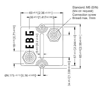
Alumina ceramic metalized with Miba Resistors ALTOX film on the bottom for improved heat transfer and optimum discharge
Encapsulation
Resin-filled epoxy casing with large creeping distance to mass, large air distance between the terminals and high insulation resistance (CTI 600)
Housing
Housings are made without color additives. The color definition is natural and can vary in different pigmentation
Contacts
Easy load connection with M4 and M5 screws
Connector height available from 25 to 42 mm
Various sleeves for increasing creeping distance up to 85 mm or potted cable connections are available on request
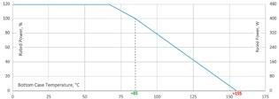
Precision High-Voltage Divider
Series MTX 2000
up to 50 W and up to 80 kV
The MTX 2000 series consists of high-quality, high-precision, high-power, high-voltage dividers for use in sophisticated resistor networks. These custom designs support a wide range of resistance value, tight voltage ratios, close tolerances and low TCRs.
Features
up to 80 kV operating voltage
up to 50 W operating power
Non-Inductive design
ROHS compliant
Technical Specifications

Resistance value see model specifications below
Resistance tolerance see model specifications below
Temperature coefficient see model specifications below Max. operating temperature -55°C to +125°C
Dielectric strength > 1000 V (25°C, 75 % relative humidity)
Load life ΔR/R 0.15 % max., 1000 h at rated power
Moisture resistance ΔR/R 0.25 % max.
Thermal shock ΔR/R 0.2 % max.
Encapsulation
Dimensions in mm
Model Specifications
standard coating: silicone conformal we recommend 2xpolyimide coating for use in oil and potted applications (ask for details)
Lead material caps, bare brass
Torque 1.8 Nm to 2 Nm for M4, 3.8 Nm to 4 Nm for M8
Connection standard version having no wire tap connection. Pre soldered wire connection available on special request
Weight depending on model no. (ask for details)
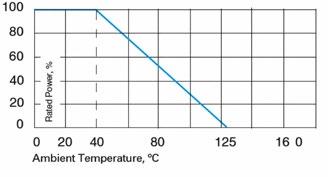
How to make a request
Model no._Ohmic Value_abs. & ratio Tolerance_ abs. & ratio TCR_ratio
For example:
Precision High-Voltage Divider
Series HVT
up to 20 kV operating voltage
The HVT series of high-voltage dividers is available in six different sizes from 5 kV to 20 kV voltage rating. In these highly reliable components, Miba Resistors combines its state-of-the-art high-voltage technology with the unique METOXFILM stability. The HVT series provide tight ratio tolerance, TCR tracking and custom-designed values.
Features
up to 20 kV operating voltage
fully customized values and ratios
on request custom designed version available; maximum ceramic substrate size 4 inch (101.6 mm)
Non-Inductive design
ROHS compliant
Technical Specifications
Resistance value
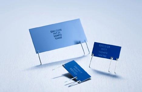
100 M and 200 M standard (other values available on special request)
Resistance tolerance absolute tolerance: ±1 % for all resistors ratio tolerance: down to +/-0.1 %
Temperature coefficient
absolute TCR: ±100 ppm/°C (at +85°C ref. to +25°C) lower absolute TCR´s available on request ratio TCR: ±25 ppm/°C (10 ppm/°C on request)
Max. operating temperature -55°C to +155°C
Voltage coefficient typical -0,4 ppm/V
Ratios 1000:1 or 100:1 (custom ratios available)
Overload 1.5 times rated voltage for 5 s. ΔR ratio 0.5 % max.
Load Life ratio ΔR with rated voltage applied for 1000 h 0.4 % max.
Moisture resistance
MIL-STD-202, method 106, ratio ΔR 0.5 % max.
Thermal shock MIL-STD-202, method 107, Cond. C, ratio ΔR 0.25 % max.
Encapsulation
Model Specifications
HVT-11, -16, -21: silicone conformal with dielectric withstanding voltage of 1000 V HVT-5, -7, -12: printed silicone coating
Lead material OFHC copper, tin-plated, 0.60 mm
Weight depending on model no. (ask for details)
How to make a request
Model no._Ohmic Value_abs. & ratio Tolerance_abs. & ratio TCR_ratio
For example:
Precision High-Voltage Divider
Series MTX 1000
up to 32 kV operating voltage
The MTX 1000 series is used for advanced resistor networks where high precision is demanded. Custom designed precision voltage dividers support a wide range of resistance value, voltage ratio, close tolerances, low temperature coefficients and voltage ratings as well as liberty for mechanical dimensions.
Features
up to 32 kV operating voltage
Absolute / ratio tolerance range ±0.1 % to ±1 %
Ohmic value and ratios per customer requirements
Non-Inductive design
ROHS compliant
Technical Specifications
Resistance value
Resistance tolerance
Temperature coefficient
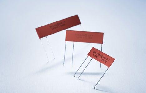
customer specified
absolute tolerance: ±0.1 % to ±1 % ratio tolerance: ±0.1 % to ±1 % depending on ohmic value
absolute TCR: ±50 ppm/°C to ±15 ppm/°C ratio TCR: ±15 ppm/°C to ±5 ppm/°C depending on ohmic value
Ratios standard ratios: 100:1, 1000:1, 10000:1 (others on special request)
Max. operating temperature -55°C to +125°C
Dielectric strength > 1000 V (25°C, 75 % relative humidity)
Insulation resistance > 10,000 MΩ (500 V, 25°C, 75 % relative humidity)
Overload ΔR/R 0.25 % max. 1.5x Pnom, 5 s.
Load life ΔR/R 0.15 % max., 1000 h at rated power
Moisture resistance ΔR/R 0.25 % max.
Thermal shock ΔR/R 0.2 % max.
Encapsulation
Model Specifications
standard silicone conformal (U) or glass coating (G) we recommend 2xpolyimide coating for use in oil and potted applications (ask for details)
Lead material tinned copper
Weight depending on model no. (ask for details)
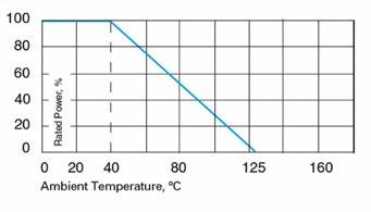
* for glass coating and 2xpolyimide coating, when used in open air, please use max. voltage x 0.6 (standard ratings valid when parts used in clean air)
How to make a request
For example:
Series 1776-X
Input Voltage Dividers for multimeters and other instruments
Miba Resistors offers a family of voltage dividers for a variety of applications, including digital multimeters, multi-range instrumentation and other range-switching devices. This line of products uses the special Miba Resistors METOXFILM.
Many special combinations of ratios, absolute & relative tolerances and absolute temperature coefficients of resistance are available. For special requirements, please contact us.
Features
Compact precision resistor networks
Easy-to-install package
Non-Inductive design
ROHS compliant
1/1
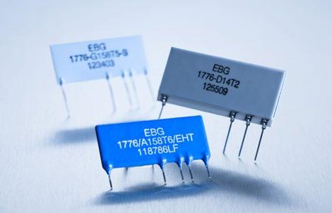
Resistance value 900 Ω to 10M Ω (see model specifications)
Ratio resistance tolerance ±0.05 % to 0.25 %
Absolute resistance tolerance ±0.1 % to 0.5 %
Ratio temperature coefficient ±10 ppm/°C to 50 ppm/°C
Absolute temperature coefficient ±25 ppm/°C to 50 ppm/°C
Voltage coefficient typical -0,05 ppm/V
Storage temperature -55°C to +165°C
Load life (ratio stability) < 0.04 %
Shelf life (ratio stability) < 0.02 % (six months)
High stability under load < 0.2 %
Number of decades 3 to 6
Model Specifications
Technical Specifications for „ X“ in model no., please select (surface finish): B - printed
Weight ask for details
Custom-designed elements available
The various types of multiple METOXFILM circuits feature the same excellent performance characteristic of other Miba Resistors metal oxide devices. Careful attention is devoted to the individual customer’s design so as to comply not only with the requirements of resistance value, tolerance and TCR, but also power handling and stability during life, even under adverse conditions.
Most of Miba Resistors multiple component designs are computer generated and thus avoid any possibility of “hot spot” long-term deterioration. In addition, trimming is accomplished in digital step fashion by computer-controlled lasers.
Miba Resistors owns several US- and European-manufactured lasers, which enable us to meet a wide range of requirements.
While Miba Resistors has developed a standard product line of voltage divider models as shown here, we are also well suited to develop an exact custom-designed circuit for you, employing high precision, high stability, low TCR and wide resistance range coverage without neglecting your important requirements.
We encourage you to consult our Applications Engineering Department about your special requirements.
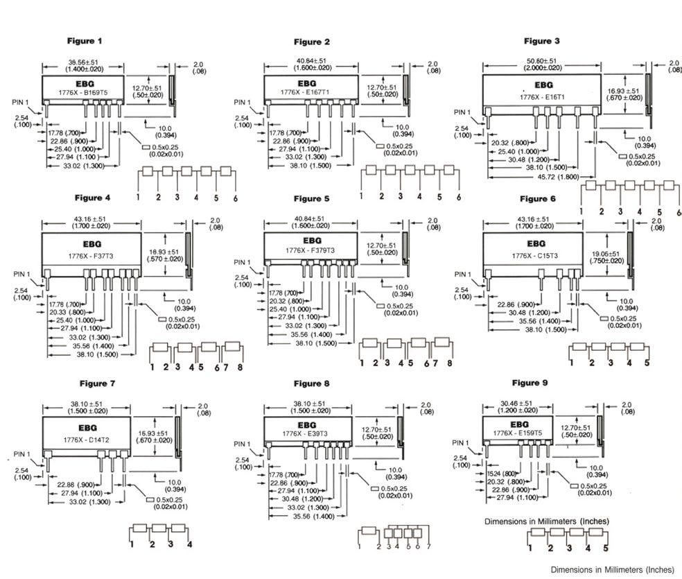
High Precision Metal Film Resistors
Series UPR / UPSC
Radial resistors, extremely precise
The advantage of Miba Resistors metal film resistors is it´s particularly high precision in terms of ohmic value, TC and long-term stability.
Features
High precision ohmic values
Low temperature coefficient precision resistors
Long-term stability
Ohmic range 10 Ω to 5 MΩ
Non-Inductive design
ROHS compliant
Technical Specifications
Resistance value
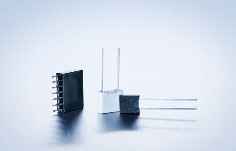
UPSC: 40 Ω to 5 MΩ
UPR: 10 Ω to 5 MΩ
Resistance tolerance ±1 % standard tolerances to ± 0.01 % on special request
Temperature coefficient ±2 ppm/°C to ±25 ppm/°C
Long-term stability better than ±0.05 % per 2000 h of operation
Std. operating temperature -55°C to +85°C
TC temperature range -10°C to +70°C (at +85°C ref. to +25°C)
Overload 6.25 times rated power for 5 s.onds at voltage not to exceed 1.5 times maximum rated working voltage, ΔR less than 0.1 % + 0.01 Ω
Load life 2000 h at 125°C ΔR less than 0.5 % + 0.01 Ω
Moisture resistance
Thermal shock
MIL -STD-202, method 106 ΔR less than 0.4 % + 0.01 Ω
MIL -STD-202, method 107, Cond. B, ΔR less than 0.2 % + 0.01 Ω
Insulation resistance > 10,000 MΩ at 250 V DC
Low temperature operation ΔR less than 0.15 % + 0.01 Ω
Dielectric withstanding voltage ΔR less than 0.15 % + 0.01 Ω
Vibration ΔR less than 0.2 % + 0.01 Ω Shock ΔR less than 0.2 % + 0.01
Dimensions
Tests
Conditions MIL-R-55182/9 Typical drifts
Power conditioning (108) 100 h/rated power at +125°C 90'/30' cycle
Thermal shock (107) 5 cycles -65°C / +150°C
Short time overload 6.25 times rated power / 5 s. Low temperature storage and operation 1h stor. 45 min rated power at -65°C
24h
± 0.02% combined test
How to make a request
Model no._Ohmic Value_Tolerance_TCR
For example: UPR 120R 0.1% 2ppm or UPSC 50R 0.1% 2ppm
High Precision Metal Film Resistors
Series EE
Molded style
The EE series conform dimensionally to the RN series of MIL-R-10509 and the RNR series of MIL-R-55182. All of Miba Resistors Metal Film Resistor series offer performances that exceed the requirements of both of these specifications. EE series can be used for automatic insertion and/or encapsulation.
Technical Specifications
Resistance value 10 Ω to 10 MΩ (other values on special request)
Resistance tolerance ±0.02 % to ±1 %
Temperature coefficient ±5 ppm/°C to ±50 ppm/°C TCR referenced to 25°C, ΔR taken at +25°C and +85°C (other TCR on special request) elements are produced and tested in accordance with MIL-R-150509, MIL-R-55182, MIL-STD-202
Special feature series UAR (ask for details)
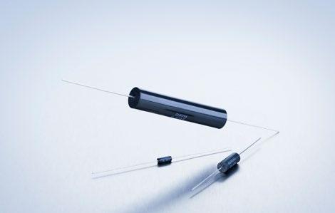
On special request, Miba Resistors will conduct a “burn-in“ of these elements for ultimate stability. Please refer to the UAR (Ultra Accurate Resistor) series and ask for a detailed datasheet!
Series NE
Molded style
Miba Resistors NE series features extremely low ranges. As a result of a special proprietary filming method, a nickel film is employed with controlled amounts of other metals, which results in fracturial resistance value availability, but with low temperature coefficient of resistance and high stability.
Technical Specifications
Resistance value 0.05 Ω ≤ 10 Ω (other values on special request)
Resistance tolerance ±0.05 % to ±5 %
Temperature coefficient according to drawing
Operating temperature -55°C to +155°C
Insulation resistance 104 MΩ at 500 V DC
Noise less than 0.05 μV/V
How to make a request
Model no._Ohmic value_Tolerance_TCR
For example: EE 1/2 10M 0.1% 5ppm or NE 1/8 10R 1% 25ppm
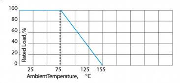
High Pulse Load Resistors
Series ESP
The ESP resistor series is the ideal solution for high pulse load / low frequency applications. High thermal capacity, suitable for applications without air cooling (better performance with cooling). The resistors are used in dumping or braking circuit.
Features
High pulse rating (ask for details)
Absorb high pulse energy within short period
High quality ceramic cylinder body with brass terminals
Good pulse load capability
Non-Inductive design
ROHS compliant
Housing materials in accordance with UL 94 V-0
Technical Specifications
ESP-62/14
ESP-62/20
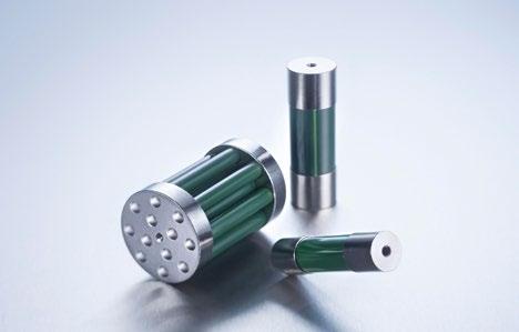
Power rating high pulse rating (ask for details)
Maximum operating voltage 1000 V (higher on request)
Pulse Energy Rating 2800 J at 1 s.
Mounting M4 scews, max. torque 3 Nm (static)
Resistance value 1 Ω to 1 KΩ (other values on special request)
Resistance tolerance ±5 % to ±10 %
Temperature coefficient ±250 ppm/°C (at +85°C ref. to +25°C)
Power rating high pulse rating (ask for details)
Maximum operating voltage 1000 V (higher on request)
Pulse Energy Rating 3300 J at 1 s.
Mounting M4 scews, max. torque 3 Nm (static)
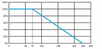
How to make a request
ESP-model no._Ohmic Value_Tolerance
For example: ESP-62/14 20R 10%
Model Specifications
Possible Pulse Load
ESP-62/20
2300 J for τ = 0.7s, time between pulses 60s
3300 J for τ = 1s, time between pules 120 s 4500 J for τ = 1.4s, time between pules 180s

Precision shunt high power resistor Shunts
Series PCS-100 M
The PCS-100 M high power resistor is made of metal foil material inside, with low temperature coefficient and good pulse withstand capability. Suitable for current sampling circuits and other applications.
Features
100 W operating power
Four-terminal Kelvin connection
SOT-227 model package
Metal foil material inside
Non-Inductive design
ROHS compliant
Housing materials in accordance with UL 94 V-0
Technical Specifications
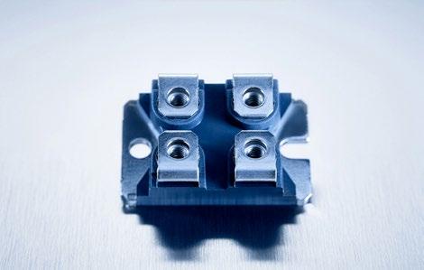
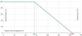
500 mΩ-1 Ω ≤200 A
Single current pulse energy ≤65 J
Power durability 1000 h at rated power at 70°C, ΔR ≤±(0.2%R + 0.001 Ω)
Thermal shock MIL-Std-202, method 107, condition A, ΔR ≤±(0.2%R + 0.001 Ω)
Moisture resistance MIL -STD-202, method 106 ΔR ±(0.2%R + 0.001 Ω)
Resistor installation M4 screw, max. torque 1.5 Nm
Lead out terminal installation M4 screw, max. torque 1.3 Nm
Operating temperature -55°C to +155°C
Dielectric strength voltage 3000 V DC Weight ~30 g
Dimensions in mm [inches]
How to make a request
PCS-100 M_Ohmic Value_Tolerance
For example: PCS-100 M 1R 1%
Alloy Shunt Resistors
Series CCS
AECQ200 ready
The CCS series is ideal for usage in frequency conversion drives and servo systems, high current battery management systems, automatic control systems, industrial instruments and equipments as well in automobile electronic control units.
Features
Special specifications can be customized
REACH compliant
ROHS compliant
Technical Specifications
Resistance value see model specifications
Resistance tolerance ±0.5 % to ±5 %
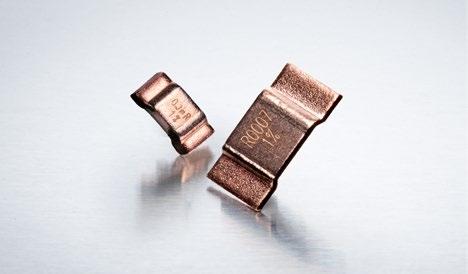
Temperature coefficient ±50 ppm/°C to ±200 ppm/°C (see model specifications)
Power rating 3 W to 15 W at 70 °C bottom case temperature (see model specifications)
Shock resistant Ideal for pulse applications
Low inductance < 3nH
Working temperature range -65 °C to +170 °C
Packaging Parts will get packed in tape & reel packaging
Weight ask for details
Dimensions in mm
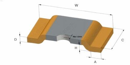
PCB-layout (reflow-soldering)
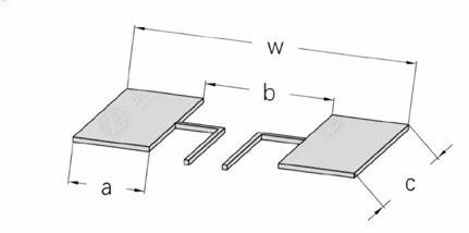
How to make a request
CCS-_Model no._Ohmic Value_Tolerance
For example:
CCS-3 0R0002 5%
Alloy Shunt Resistors
Series CCS
Model Specifications
*TCR (ppm°C): Test was conducted with the temperature from 20°C to 120°C, while 20°C worked as reference
Series CCS
Pulse Power Curve CCS 3
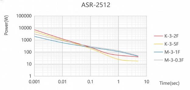
Pulse Power Curve CCS 5
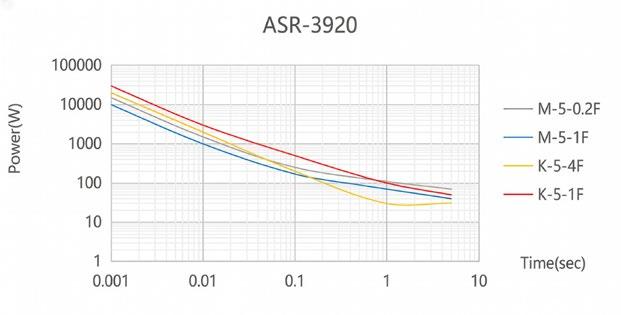
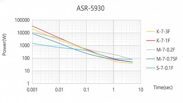
Derating Curve Pulse Power Curve CCS 7
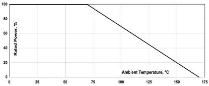
Alloy Shunt Resistors
Series CCS
AECQ200 ready
Endurance Test
Items
Temperature cycling
ESD
High temperature exposure
Board flex test
HumidityBias
High temperature operating life
Terminal strength (SMD)
Solderability
Resistance to soldering heat
Short time overload
Vibration
Flame retardance
Requirements Reference
1000 cycles (-55°C to +155°C), unpowered.
Minimum dwell time 15 min. at each temperature extreme.
Maximum transition time 1 min. Measurement at least 24 h after test conclusion.
1) Direct Contact (DC): ±6 kV
2) Air Discharge (AD): ±12 kV, ±16 kV, ±25 kV
1000 hrs. (T=170°C), unpowered.
Measurement at 24±4 h after test conclusion.
Apply an external force once to the circuit board, bend at least Dx = 2mm, duration 60+5s.
1000 hrs (85°C/85%RH.)
Note: specify conditions: 10% of rated power.
Measurement at 24±4 h after test conclusion.
1000 hrs. (T=125°C).
Rate power was applied to the products intermittently: 90 minutes ON and 30 minutes OFF.
Measurement at 24±4 h after test conclusion.
Apply an external force once to the side of the test device, the force is 17.7N (1.8kg), duration 60+1s.
Weld bath temperature 245°C±5°C, duration 5±0.5s.
250°C±5°C, 30s±5s
Apply 5 times the rated power for 5 s.and release the load for about 30 minutes, then measure its resistance variance rate.
20 min. (5 g‘s), test from10Hz-2000 Hz, 12 cycles each of 3 orientations
1.) Test power: 100%, 115%, 130%, 150% (rate power)
2.) Test duration: 1h
Resistance to solvents
Note: add aqueous wash chemical - OKEM clean or equivalent. Do not use banned solvents.
JESD22-A-104 ±0.5 %
AEC-Q200-002 Rev-B ±0.5 %
MIL-STD-202 method 108 ±0.5 %
AEC-Q200-005 ±0.5 %
MIL-STD-202 method 103 ±0.5 %
MIL-STD-202 method 108 ±0.5 %
AEC-Q200-006 ±0.5 %
J-STD-002 95% Coverage Minimum
MIL-STD-202 method 210 ±0.5 %
MIL-STD-202 method 301 ±0.5 %
MIL-STD-202 method 204 ±0.5 %
AEC-Q200-001
MIL-STD-202 method 215
Mechanical shock
1) Pulse waveform: half-sine pulse
2) Accelerate peak: 100g‘s
3) Pulse duration: 6ms; 4) Orientation & shock time: ±X, ±Y, ±Z, 3 times each orientation, total 18 time
The temperature is not higher than 350 °C for more than 10 s., no flame, no explosion.
There was no missing, faded, smeared, blurred, or shifted (dislodged) with the marks. There was no crack, separation, crazing, swelling, softening, degradation on the samples.
MIL-STD-202H, method 213 ±0.5 %
High Energy Carbon Ceramic Resistors
Series CD
Absorb high pulse energy, suitable for high pulse, overload or other harsh working environments. Used for electrical transmission, traction, pulse power supply, inductive heating, and other applications.
Features
100 % active materials
Non-Inductive design
Up to megahertz frequency
Air / SF6 environments
Materials in accordance with UL 94 V-0
Technical Specifications
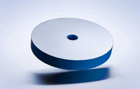
Resistance value see model specifications below (other values on special request)
Resistance tolerance ±10 % to ±20 %
Temperature coefficient -500 ppm/°C to -1500 ppm/°C
Linear expansion coefficient 5 ppm/°C to 15 ppm/°C
Density ~ 2.6 (g / cm³)
Max. operating temperature ≤ 150°C (continuous operation) ≤ 200°C (infrequent operation)
Thermal conductivity 4.5 W / m x °C
Thermal capacity 2 J / cm³ x °C
Inductance negligible
Termination standard metallised contacts is nickel (brass is available)
Default coating material epoxy coating (silicate coating is available) Weight depending on model no. (ask for details)
Model Specifications
De-rating for other ambient temperatures (Ta °C) Max. injection energy @25 °C & max. rated power @25 °C by the ratio (150 - Ta) / 125
Dimensions in mm
How to make a request
Model no._Ohmic value_Tolerance
For example: CD50 2R5 10%
Applicable Standard
IEC60115-1 : 2001 (GB/T5729-2003)
MIL-STD-202
MIL-R-39009D
High Energy Carbon Ceramic Resistors
Series CD
Max voltage withstand per cm of disc length (Vw)
V (rms) : Vw (air) = 0.87 x (R/TxA/L) 0.3
V (impulse) : Vw (air) = 4.3 x 1.2 √log(R/2.54 x A/L)
Cooling time
Thermal time constant:
Kv/cm (T = insertion time)
Kv/cm (1.2 / 50 μs waveform)
A = cross section area (cm²)
L = length (cm)
T(s) = Emax. (25°C) / Wmax. (25°C) Emax. (25°C): insertion energy Wmax. (25°C): rated power
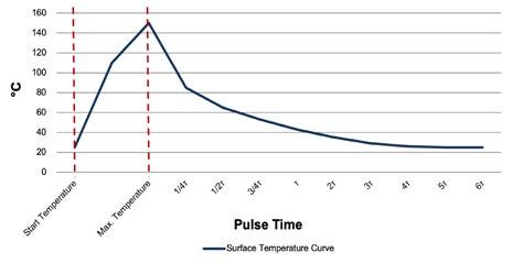
Non-repetitive operations and multi-cycle repetitive operations are different. For repetitive operations, the heat accumulation needs to be considered, and sufficient cooling interval cycles are required.
For repetitive multi-cycle operations, heat sink or cold plates can be used for air cooling or water cooling.
Mounting
Full cooling time: 4T
Note: the heat dissipation efficiency is related to the surface area, the curve is the typical value for single disc . For multiple discs in one stack, the heat dissipation would be much lower, and take longer time of cooling.
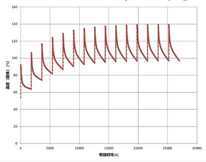
The terminal of the CD disc resistor series is flame sprayed with Ni, mounting is needed for electrical contact. Depending on the application parameters like energy and power, choose the proper dimension and quantity, use mounting rack or bus bar while necessary.
For good electrical contact, enough mounting force should be applied to the disc.
Mounting force: F = 24 x (Do-Di) 0.7 (±50 %) kg
Do: outer diameter
Di: inner diameter
Examples for mounting structures
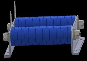
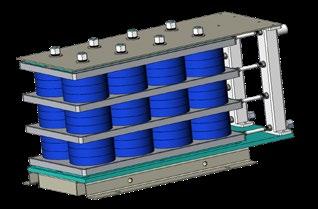
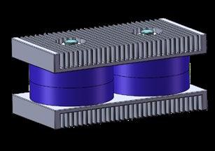
High Energy Carbon Ceramic Resistors
Series CSR
High Energy Resistor, PCB mounting
High energy pulse capability, suitable for electrical transmission, traction, pulse power supply, inductive heating, and other applications.
Features
100 % active materials
Low inductance, suitable for HF applications
Compact size
PCB mounting
Epoxy coating with good humidity resistance
ROHS compliant
Materials in accordance with UL 94 V-0
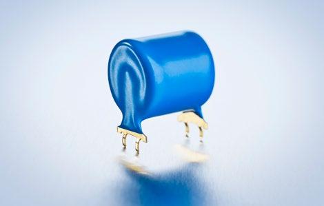
Technical Specifications
Resistance value see model specifications
Resistance tolerance ±20 % standard (±10 % on special request)
Temperature coefficient -500 ppm/°C to -1500 ppm/°C
Linear expansion coefficient ~5 ppm/°C to 15 ppm/°C
Long term working temperature up to 150°C (slight color change is normal, without functional influence)
Max. pulse voltage (kV) (1.2 / 50 μs) see model specifications
Max. AC working voltage (50 Hz / rms) see model specifications; t = insertion time (ms)
Thermal time constant T (s) = Emax (25°C) / Wmax (25°C), cooling t ≥ 4 T
Contact
Model Specifications
4 terminal spring contact for stable PCB mounting, the PCB hole diameter of ~2-3 mm is recommended. Mild solder material with melting point of 230°C or less is suggested
Terminals gold plated brass material (other terminal options available on request)
Weight depending on model no. (ask for details)
How to make a request
CSR_Ohmic value_Tolerance
For example: CSR-29 100R 20%
Applicable Standard
IEC60115-1 : 2001
Dimensions
Carbon Composite Energy Absorbing Resistor
Series CSP
PCB energy absorption resistor, patent ZL2017 3 0547996.2
The CSP series resistors are made of inorganic materials such as graphite and Al2 O3 through high-temperature sintering. Solid core conductive mechanism, non-inductive design and suitable for high frequency applications. The surface is encapsulated with epoxy resin, which has good sealing and moisture-proof properties. It can absorb random strong pulse energy discharge in a short period of time and is suitable for power transmission, electric traction, pulse power supply, induction heating and other applications.
Features
Non-inductive, the operating frequency can reach MHz level
PCB plug-in design, easy to install
Compact size
High pulse load capability
Materials in accordance with UL 94-V0, ROHS compliant
Technical Specification
Resistance value see specifications below Resistance tolerance ±10 % (lower on request)
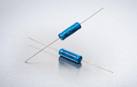
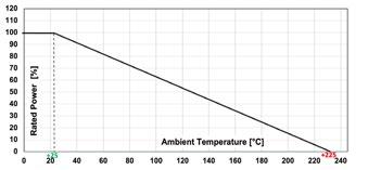
Temperature coefficient -800 ppm/°C ~ 1000 ppm/°C Linear expansion coefficient 5 ppm/°C - 15 ppm/°C
Power rating see specifications below
Load stability under rated power, lasting for 1000 h, resistance change ≤5 %
Temperature impact characteristics -55°C ~ +125°C, 10 times, resistance change ≤2 %
Moisture resistance characteristics MIL-ST-202, method 103, resistance change ≤3 %
Overload characteristics 10 times rated power, lasting 5s, resistance change ≤2 %
Encapsulation: high temperature resistant epoxy resin coating, smooth and hard surface and good appearance. When working in an envirment above 150°C for a long time, the surface coating my decompose slightly and the colour may change but it will not effect the performance of the resistor.
Model specifications and dimensions
Dimensions in mm [inches]
How to make a request CSP_Ohmic value_Tolerance
Carbon Composite Energy Absorbing Resistor
Series CW/CX/CY/CZ
PCB energy absorption resistor 1/1
The resistors of this series are made of inorganic materials such as graphite and AI2O3 which are sintered at high-temperature. Solid core conductive mechanism, non-inductive design and suitable for high frequency applications. The surface is encapsulated with epoxy resin, which has good sealing and moisture-proof properties. It can absorb random strong pulse energy discharge in a short period of time and is suitable for power transmission, electric traction, pulse power supply, induction heating and other applications.
Features
Non-inductive, the operating frequency can reach MHz level
PCB plug-in design, easy to install
Compact size
High pulse load capability
Raw materials pass UL 94-V0 standard
Technical Specification
Resistance value see specifications below
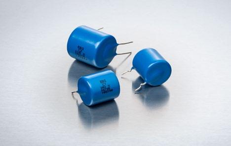
Resistance tolerance ±10 % to ±20 % (lower on request)
Temperature coefficient -500 ppm/°C to -1500 ppm/°C lower TCR on special request
Linear expansion coefficient 5 to 15 ppm/°C
Power rating see specifications below
Operating working voltage 50 Hz power frequency, rms: 2.4 x (1.8R/t)03
Maximum pulse voltage (kV)
1.2/50 µs impact: 1.26R x (-1+√(1+33/R)) 10/1000 µs shock: 0.0627R x (-1+√(1+658/R)) 500/5000 µs shock: 0.0126R x (-1+√(1+3288/R))
Maximum operating temperature 150°C (continous) 200°C (non continous)
Thermal time constant (s) = Emax (25°C) Wmax (25°C), cooling time t≥4r
Encapsulation: high temperature resistant epoxy resin coating, smooth and hard surface and good appearance (when working in an envirment above 150°C, for a long time, the surface coating my decompose slightly and change color but it will not effect the performance of the resistor.
Welding: it it recommended to use an active mild flux with a melting point blow 230°C. If the test temperature range exceed the specifications, ask for details.
Model specifications and dimensions
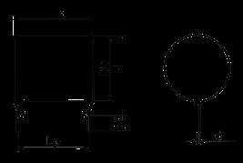
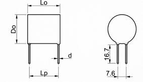
How to make a request
Model no._Ohmic value_Tolerance _TCR
For example: CY 50R 10%
CW - CY CZ
Water Cooled High Power Resistors
Series LCR6000
The resistor is made of metal alloy structure. Direct water cooling with high purity water (or 50% ethylene glycol) shows better results compared to traditional cooling method. Found applications in electricity generation, transmission or electrical drive system.
Features
PVDF resistor case and water channel can withstand high pressure, temperature and acid environment to guarantee long-term reliability
Spiral water channel can reduce water flow resistance. Symmetric metal alloy minimizes the parasitic reactance
The resistive alloy plate is stamping processed
The resistor is assembled with special technique to meet the vibration and shocking requirements
Technical Specifications
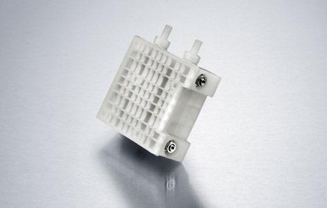
Resistance value 1 Ω to 130 Ω (others on special request)
Resistance tolerance ±1 % to ±5 %
Temperature coefficient ±150 ppm/°C (referenced to +25°C, ΔR taken at ~+100°C)
Cooling water conductivity: < 0.5 μS / cm
Cooling water temperature: outlet temp. ≤ 65°C (avoid boiling)
Cooling water temperature rise: ΔT = (P x 60) / (L x 4200) P = rated power ( W) / L = flow rate (l/min.)
Rated power
With above conditions, when water inlet temperature ≤ 50°C, cooling water temp. rise ≤ 15°C, the flow rate and rated power are as following:
6 l/min: Pmax = 6 kW
(inlet/outlet pressure difference ≤ 1.2 bar, ref.)
8 l/min: Pmax = 8 kW (inlet/outlet pressure difference ≤ 1.7 bar, ref.)
Short time overload 1.5 rated power, 5 s, ΔR ≤ ± (1%R + 0.05 Ω)
Dielectric strength voltage 11 kV rms, 50 Hz, 1 min.
Max. peak voltage 8.5 kV
Inductance ≤ 4 mH
Capacitance / mass ≤ 100 pF
Vibration test amplitude 0.75, frequency 10 ~ 55 Hz, 2 h, ΔR ≤ ± (1%R + 0.05 Ω)
Air distance > 17 mm
Case material PVDF CTI ≥ 600, in compliance with UL 94 V-0
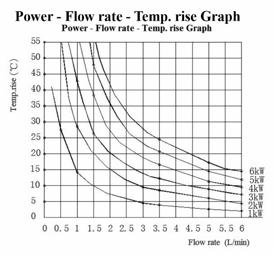
How to make a request
LCR6000_Ohmic Value_Tolerance
For example: LCR6000 60R 5%
Applicable Standard
IEC60115-1 : 2001 (GB/T5729-2003)
MIL-STD-202
MIL-R-39009D
Q/EBG007-2012 company standard
Dimensions in mm
Further Option
without threaded bolt for mounting possible (ask for details)
Wirewound Resistors
Series CWR
The high power resistors from Miba Resistors offer safe and reliable operations for PRE- and DISCHARGE applications in power distribution units and inverters.
Features
Excellent insulation performance
High power load capacity
Strong overload capability
Standard 250 terminal
mounting clips as an option available (ask for details)
Technical Specifications
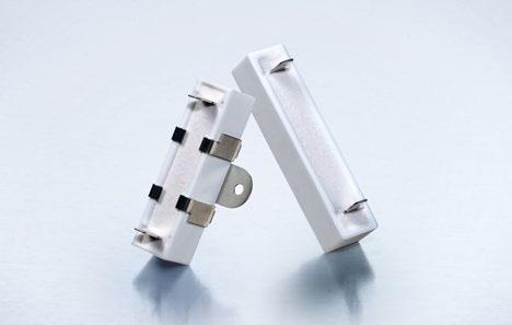
Dimensions
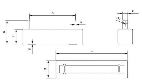
Derating curve
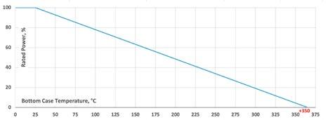
Wirewound Resistors
Series RST5N
60 W Resistor
The RST5N resistor series is a robust resistor for extreme high Pre-charge pulses. Suitable for high voltages up to 1000V.
Features
60 W operating power
High voltage capable
Extreme pulse capability
External cooling possible
Easy connection via Fast-on
Robust design
Technical Specifications
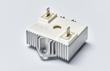
Resistance value 25 Ω to 200 Ω (other values on special request)
Resistance tolerance ±5 % to ±10 %
Temperature coefficient ≤ 1000 ppm/°C (referenced to 25 °C, ΔR taken at ~105°C)
Power rating 60 W at 85°C bottom case temperature
Short time overload 2800 W at 70°C for 5s, ΔR = 0.5% max., one time
Maximum operating voltage ≤ 1000 V DC (pre-charge voltage)
Dielectric strength voltage 3 kVrms, 1 min., 50 Hz Leakage current < 1mA
Insulation resistance 500 MΩ at 1000 V, 10s.
Resistor installation M5 screw, max. torque 3 Nm
Operating temperature -55°C to + 155°C
Weight ~156g
Dimensions in mm
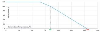
Derating (thermal resist.) RST5N:
Miba power resistor cooling requirements
How to make a request
RST5N_Ohmic Value_Tolerance
For example: RST5N 470R 5%
Wirewound Resistors
Series RST 100
100 W Power Resistor
AECQ200 ready
Can absorb high pulse energy within short period. Have high thermal capacity. Used in dumping, breaking circuit etc.
Features
100 W operating power
Aluminum housing for better heat dissipation
Different connection possible (FAST-ON, wires)
Huge short time overload capability
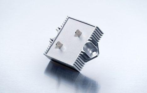
Technical Specifications
Resistance value range 10 Ω to 200 Ω
Resistance tolerance ±5 % to ±10 %
Temperature coefficient ± 500 ppm/°C (referenced to 25 °C, ΔR taken at ~105°C)
Power rating 100 W at 70°C
Operating voltage ≤ 1000 V DC (pre-charge voltage)
Insulation resistance 1000 V DC min. 500 MΩ
Short time overload 2800 W, 70°C 3s
Single maximum impact pulse 2500 J (t=0.5s)
Dielectric strength 3kV rms, 50 Hz, 1 min.
Operating temperature -55°C to +225°C
Mounting M5 screw
Weight ~ 149 g
Dimensions in mm
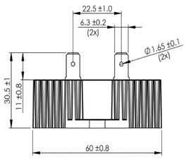
How to make a request
RST100_Ohmic Value_Tolerance
For example:
RST100 35R 5%
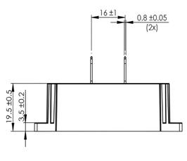
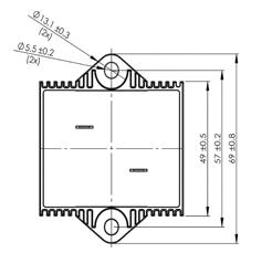
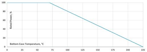
Wirewound Resistors
Series RST 150
150W Power Resistor
AECQ200 ready
Can absorb high pulse energy within short period. Have high thermal capacity. Used in dumping, breaking circuit etc.
Features
150 W operating power
Aluminum housing for better heat dissipation
Different connection possible (FAST-ON, wires)
Extremely strong pulse capacity and can withstand shortterm overload and short circuit for a long time
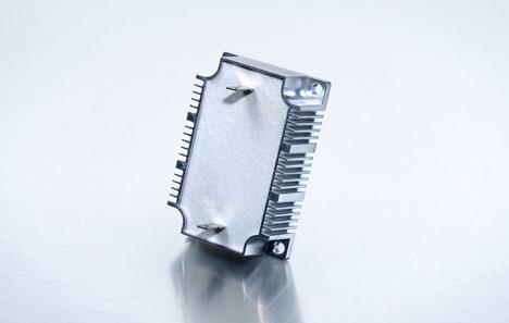
Technical Specifications
Resistance value 10 Ω to 300 Ω
Resistance tolerance ±5 % to ±10 %
Temperature coefficient ± 500 ppm/°C (referenced to 25 °C, ΔR taken at ~105°C)
Power rating 150 W at 70°C
Operating voltage ≤ 1000 V DC (pre-charge voltage)
Insulation resistance 1000 V DC, min. 500 MΩ
Short time overload 3000 W, 70°C 3s
Singel maximum impact pulse 3000 J (t=0.5s)
Insulation layer withstand voltage 3.5 kV rms, 50 Hz, 1 min.
Operating temperature -55°C to +225°C
Mounting M5 screw Weight ~225 g
Dimensions in mm
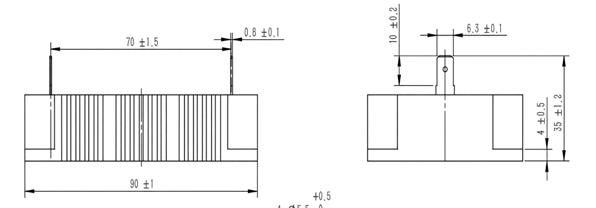
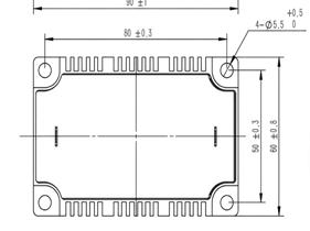
How to make a request
RST150_Ohmic Value_Tolerance
For example:
RST150 200R 5%
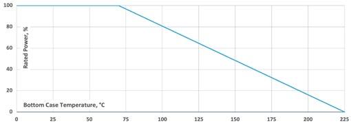
Wirewound Resistors
Series RST 200
200W Power Resistor
AECQ200 ready
Features
200 W operating power
Aluminum housing for better heat dissipation
Different connection possible (FAST-ON, wires)
Extremely strong pulse capacity and can withstand shortterm overload and short circuit for a long time
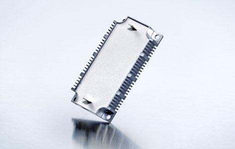
Technical Specifications
Resistance value 10 Ω to 300 Ω
Resistance tolerance ±5 % to ±10 %
Temperature coefficient ± 500 ppm/°C (referenced to 25 °C, ΔR taken at ~105°C)
Power rating 200 W at 70°C, continuous load requires a heat sink
Operating voltage ≤ 1000 V DC (pre-charge voltage)
Insulation resistance 1000 V DC, min. 500 MΩ
Short time overload 3000 W, 70°C 3s
Singel maximum impact pulse 4000 J (t=0.5s)
Insulation layer withstand voltage 3.5 kV rms, 50 Hz, 1 min.
Operating temperature -55°C to +225°C
Mounting M5 screw Weight ~285 g
Dimensions in mm
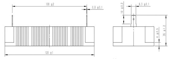
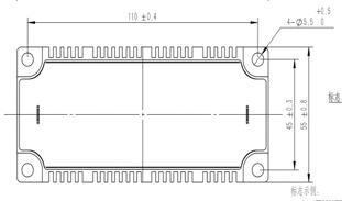
How to make a request
RST200_Ohmic Value_Tolerance
For example:
RST200 200R 5%
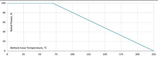
OUR LOCATIONS
Miba Power Electronics Group
Miba Resistors Austria Kirchbach, Österreich
Miba Electronics Slovenia Šentjernej, Slowenien
Miba Resistors US Middletown, PA, USA EBG China* Qingxi / Shenzhen Area, China
www.miba-resistors.com
Contact details:
Miba Resistors Austria GmbH Kirchbach 384
8082 Kirchbach-Zerlach AUSTRIA
T + 43 3116 2625 0
F + 43 3116 2076
sales.mra@miba.com
North American Sales - Distribution
Miba Resistors US LLC 460 Spruce Street Middletown, PA 17057
USA
T +1 717 737 9877
F +1 717 737 9664
sales@mibaresistors.com