Oyindamola Akinyebo
Portfolio
ARCHITECTURE
2 Contents Academic Study Personal Project Practice Experience Technical Studies Pg 3-11 Pg 12-13 Pg 14-17 Pg 18
Academic Study
Artful Healing: An Art Therapy School
Thesis:
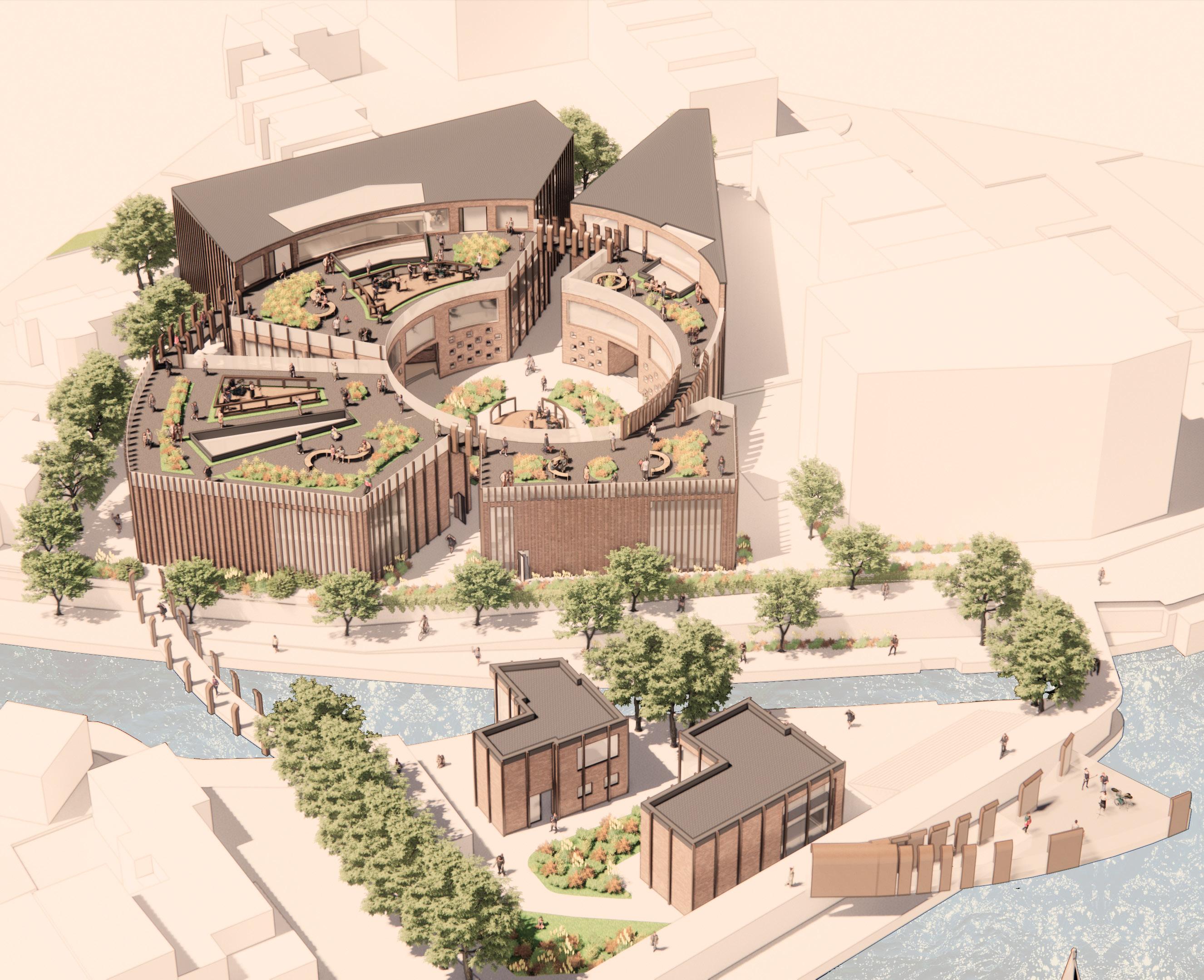
The art therapy school explores humanity’s journey through life. Life is a constant spiral of freeing ourselves from our limitations. As a species, we are restricted by our technology. As infants, we are restricted by our knowledge, size, and communication skills. The journey through infancy to adolescence provides the opportunity for us to free ourselves from these limitations however, we are constantly faced with new ones. This is the spiral of life.
‘Art has the extraordinary capacity to express resistance and rebellion, protests, and hope. It is a vital contribution to any flourishing democracy’ –Deeyah Khan
The arts are disciplines that focus on freedom of expression. Through the arts, we can free ourselves from the limitations of infancy, adolescence, and adulthood as it is all about feeling free to express ourselves in an environment where there is no right or wrong answer: we can unapologetically be ourselves.
The stigma that surrounds mental health, can be seen as a limitation that we need to break free from. The path to freedom is not always easy or clear so, the art therapy school will be a compass, guiding the local community and students on this journey. The school aims to adopt artistic disciplines – visual art, dance, drama, and music – as a tool towards freedom, becoming a safe haven for all.
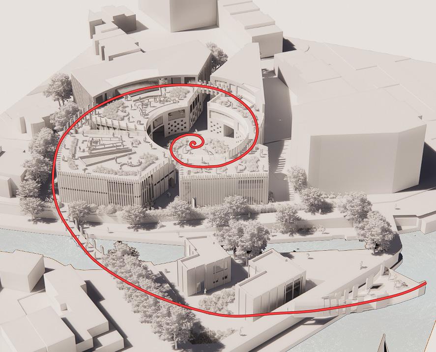
Waterside Meadow Lane Lock, the site for this school, is bounded by two water bodies: the river Trent and the canal. These water bodies can be related to humans through the Fibonacci, which is a sequence that relates the scale of nature (including humans) to science and geometry. The school will adopt this geometry through its form, to represent the journey through life’s limitations.
Through its form, this school will represent the movement from restriction to freedom through a combination of narrow corridors and open plan spaces, walls become restrictive pathways, and classrooms and studios become the light at the end of the tunnel, where freedom from the struggles of life are encouraged through the artistic disciplines.
3
Academic Study
Massing Strategy:
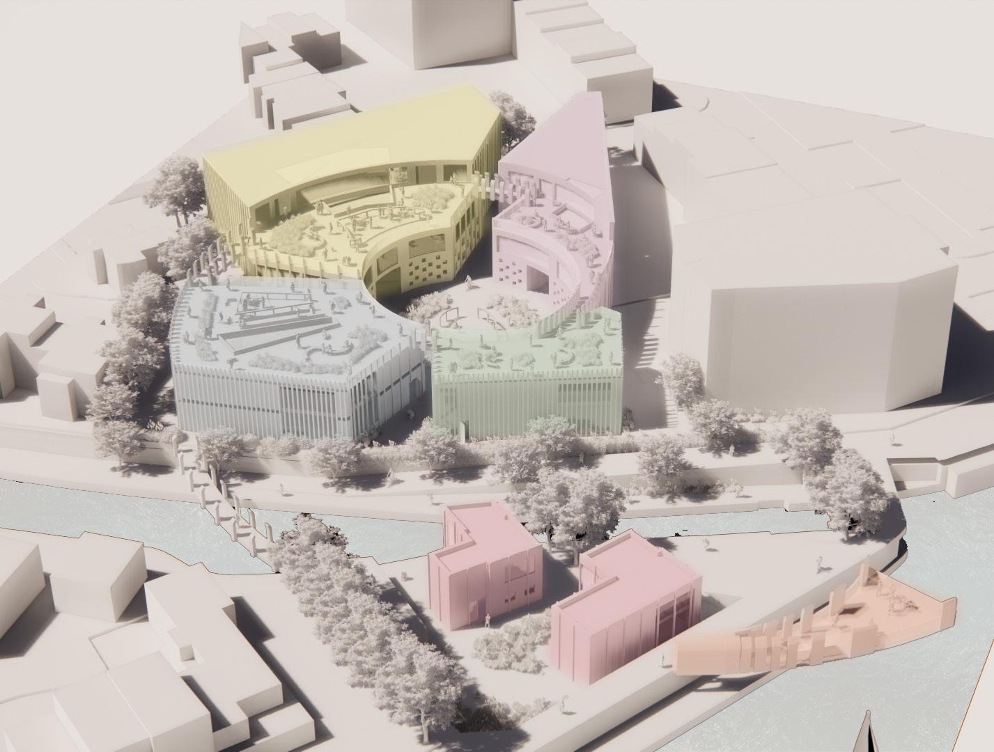
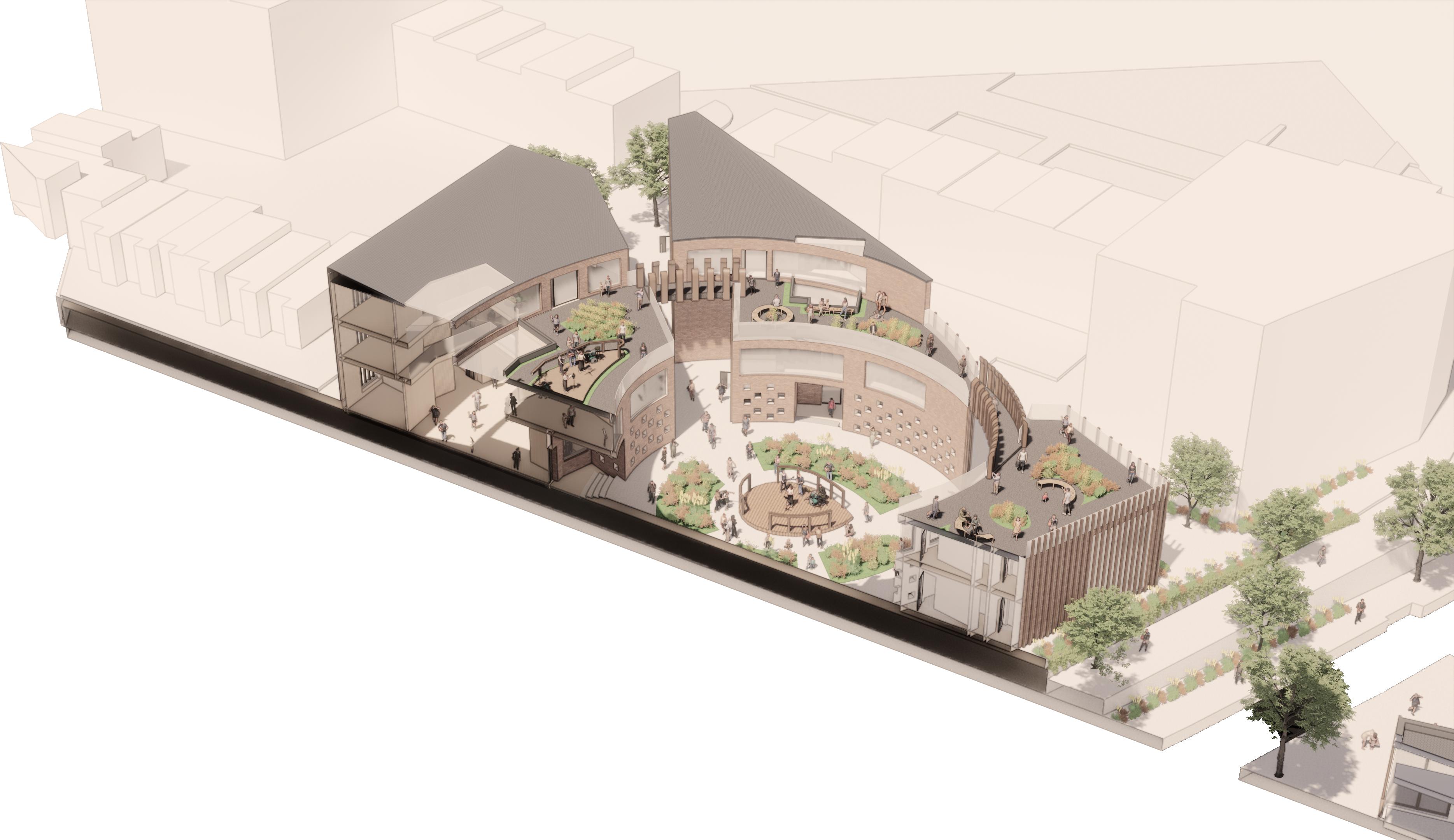
The massing strategy divides the art therapy disciplines into specialised environments: music, art, dance, and drama. Educational buildings are on the north side, while the re purposed lock house buildings on the south serve as a relaxation (downtime) centre. Students can unwind near nature to alleviate stress. Interdisciplinary interaction is facilitated by a water pavilion acting as a multipurpose space for exhibitions, symbolising the journey’s end.
Geometry Strategy:
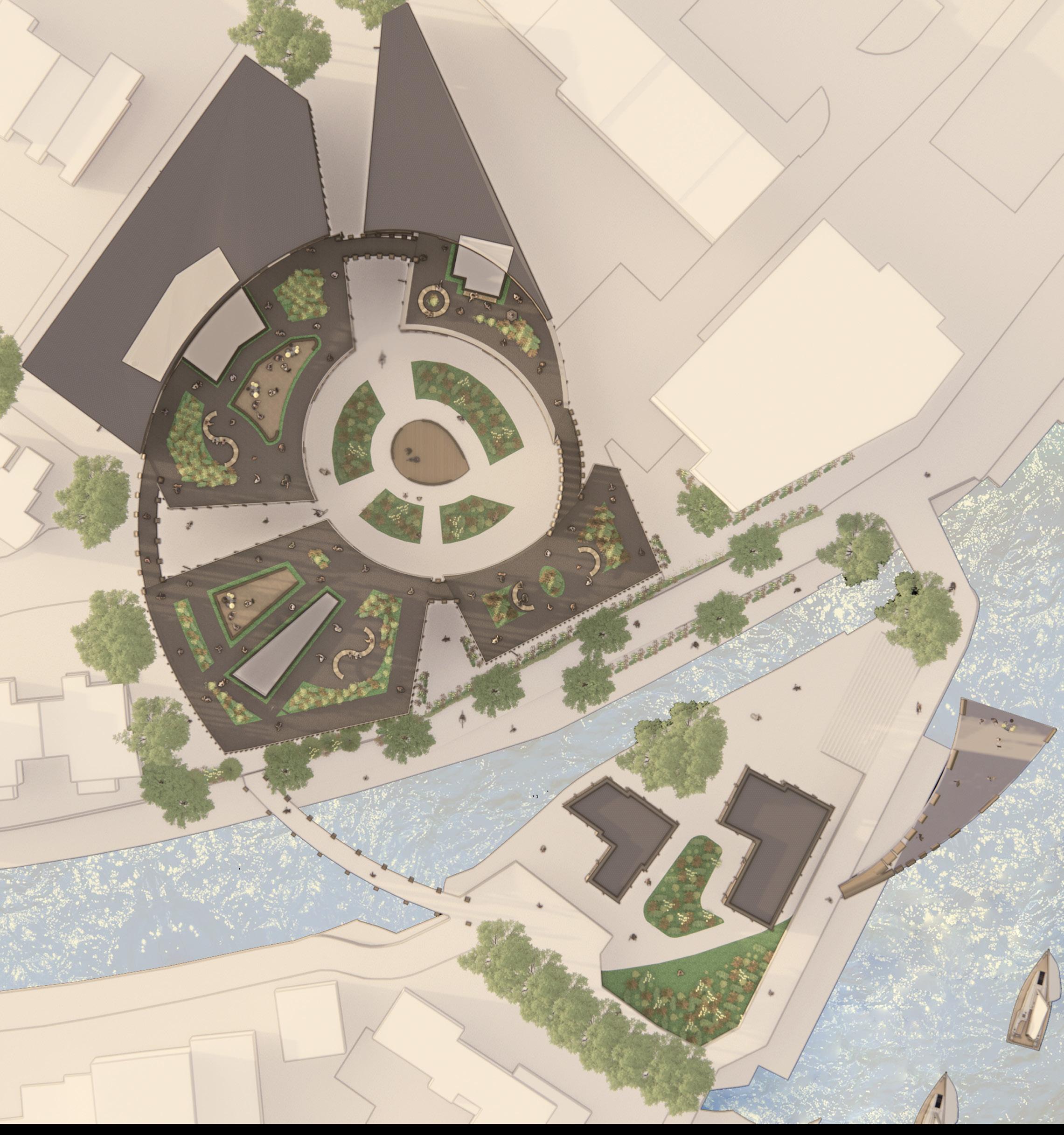
The Fibonacci sequence links nature to science and geometry. Inspired by the journey from restriction to freedom and the site’s natural surroundings, my design employs the Fibonacci spiral to connect art therapy buildings and site sections. The public square marks the spiral’s tightest point. Moving outward, the spiral symbolizes freedom toward nature, represented by water bodies. The water pavilion at the spiral’s end offers an exhilarating experience with a glass base, blurring boundaries between man and nature, mirroring life’s journey.
Site Access Strategy:
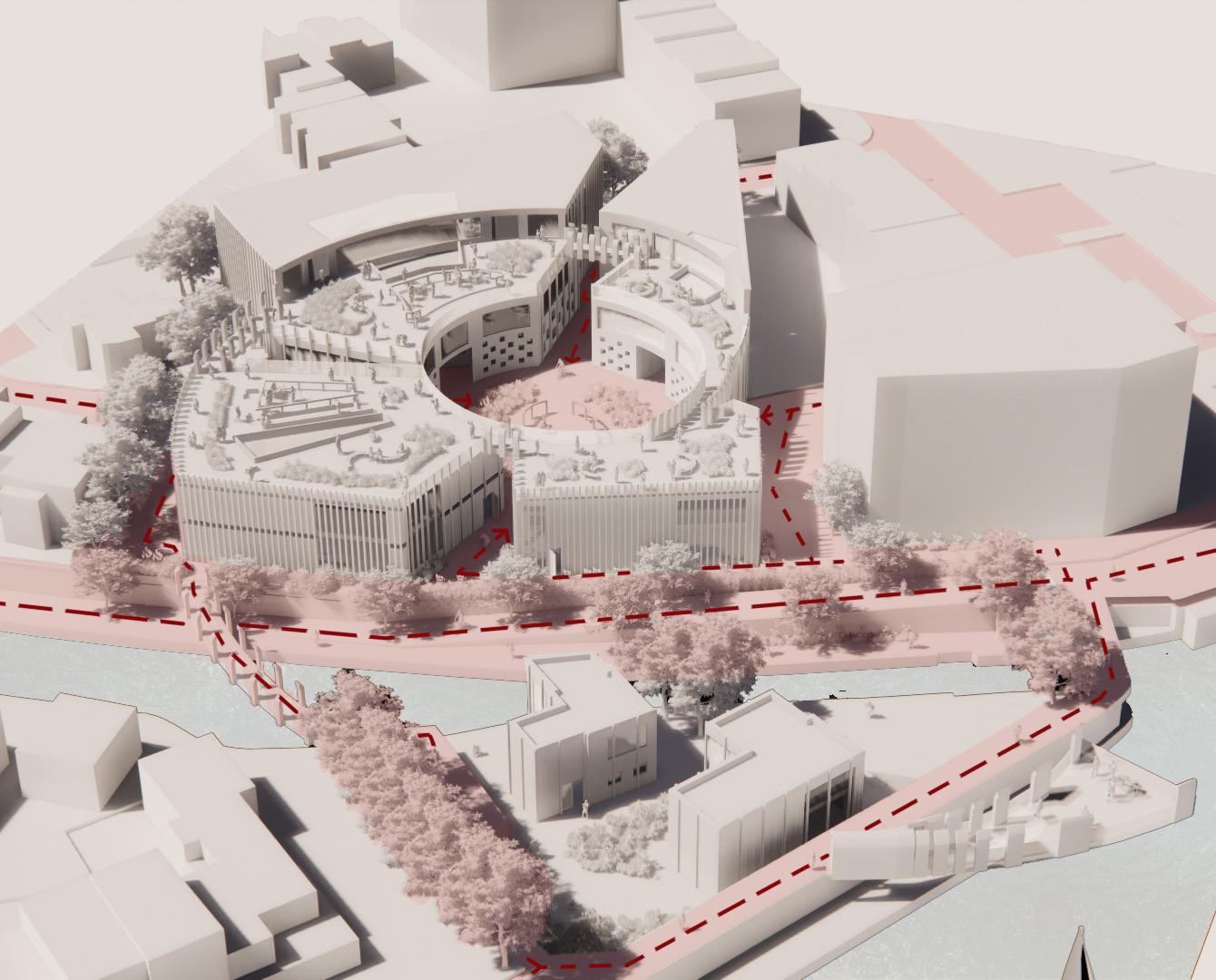
The existing site has four main access points, including the canal-side path. Integrating these points into the access strategy allows for through routes within the school’s massing design, converging at the central public square.
To facilitate wheelchair-friendly pedestrian access between the north and south parts of the site, I designed a bridge following the overall Fibonacci arrangement of the design.
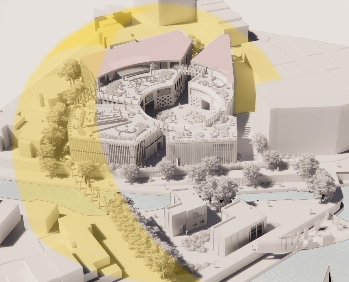
Solar Gain Strategy:
The school design includes a central courtyard for natural sunlight penetration. Solar panels are integrated for renewable energy. Roof slopes of Music and Art buildings follow the sun’s path to enhance solar energy production.
4
Music department & Multi-disciplenry Amenities Art Department Drama Department Dance Department ‘Downtime Centre’ for relaxation Water Pavillion
5 Ground Floor plan N
First Floor plan N
Academic Study
6
MUSIC DEPARTMENT ART DEPARTMENT DANCE DEPARTMENT DRAMA DEPARTMENT ‘DOWNTIME’ RELAXATION CENTRE WATER PAVILLION Second Floor plan N Roof plan N
Academic Study
Academic Study
7
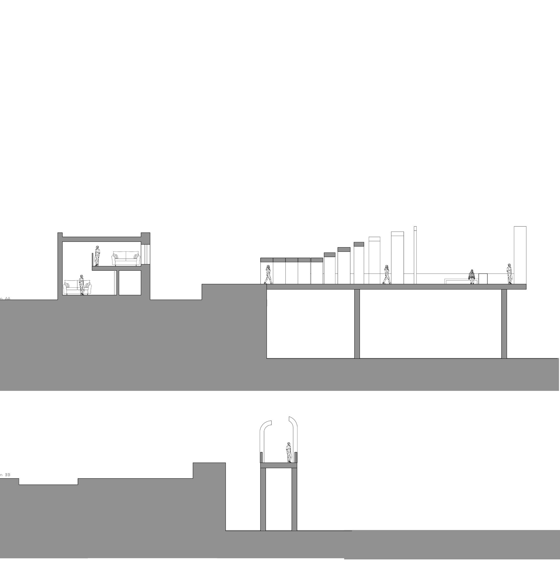
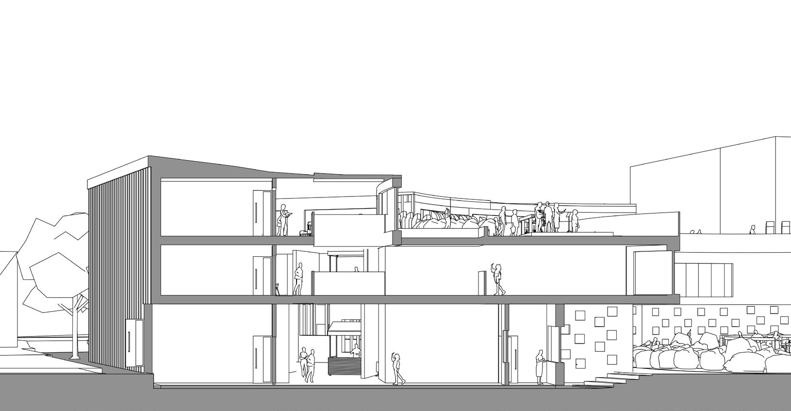
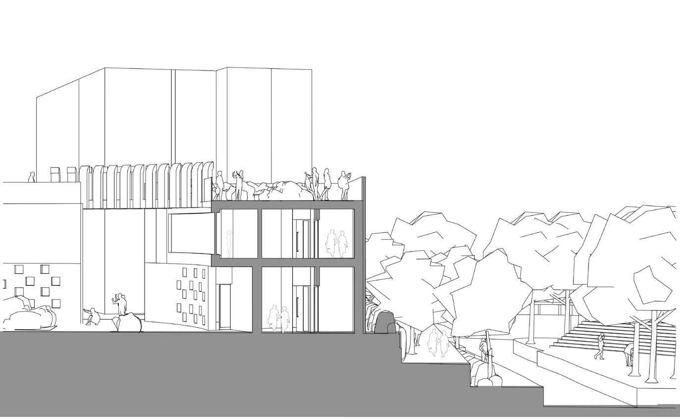
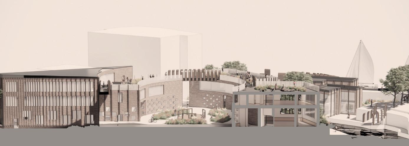
Section AA
Section CC
Section CC
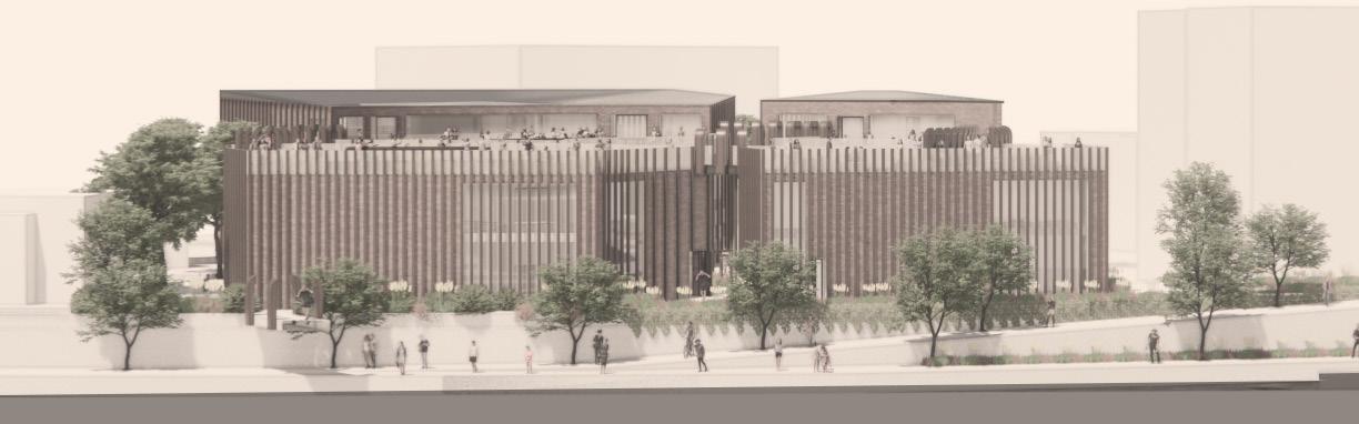
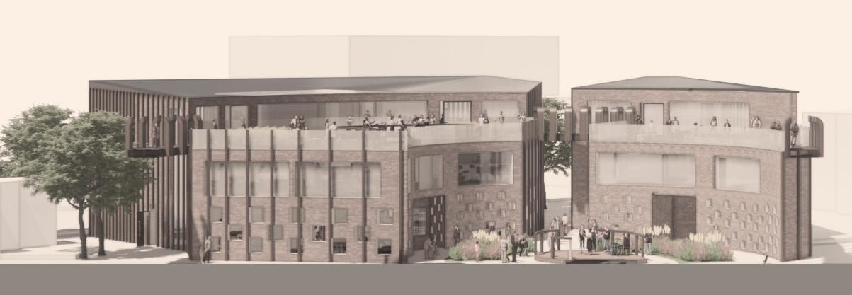
Elevation 1
Elevation 2
Elevation 3
Academic Study
The Journey
1.
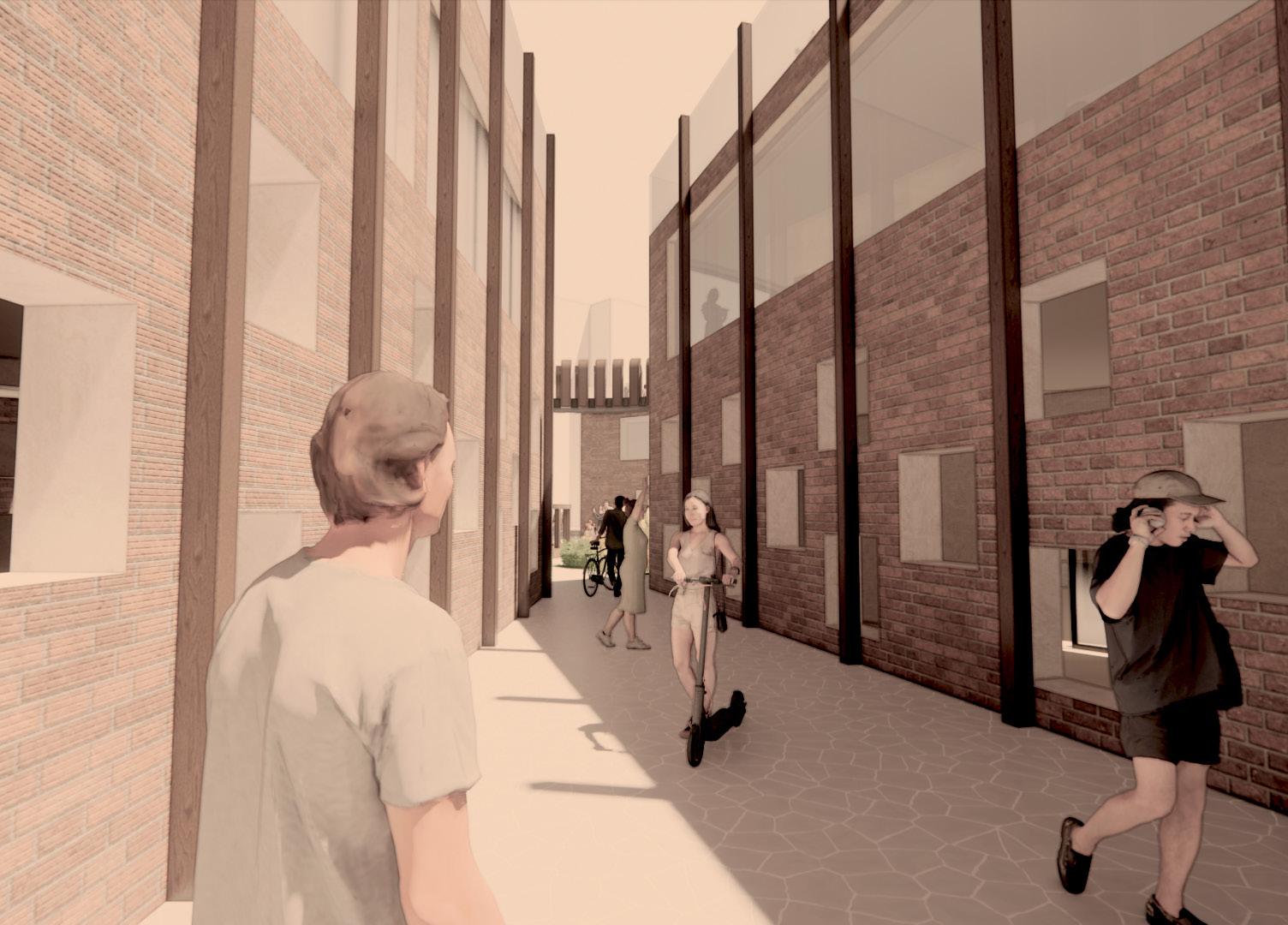
THE APPROACH:
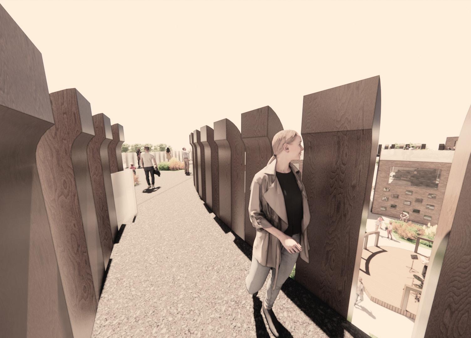
ROOF BRIDGES:
This visual shows the roof bridges that connect the buildings of the 4 art therapy disciplines (art, music, dance, drama) together
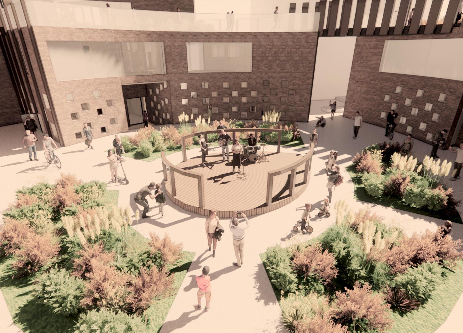
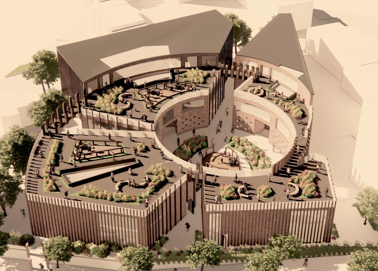
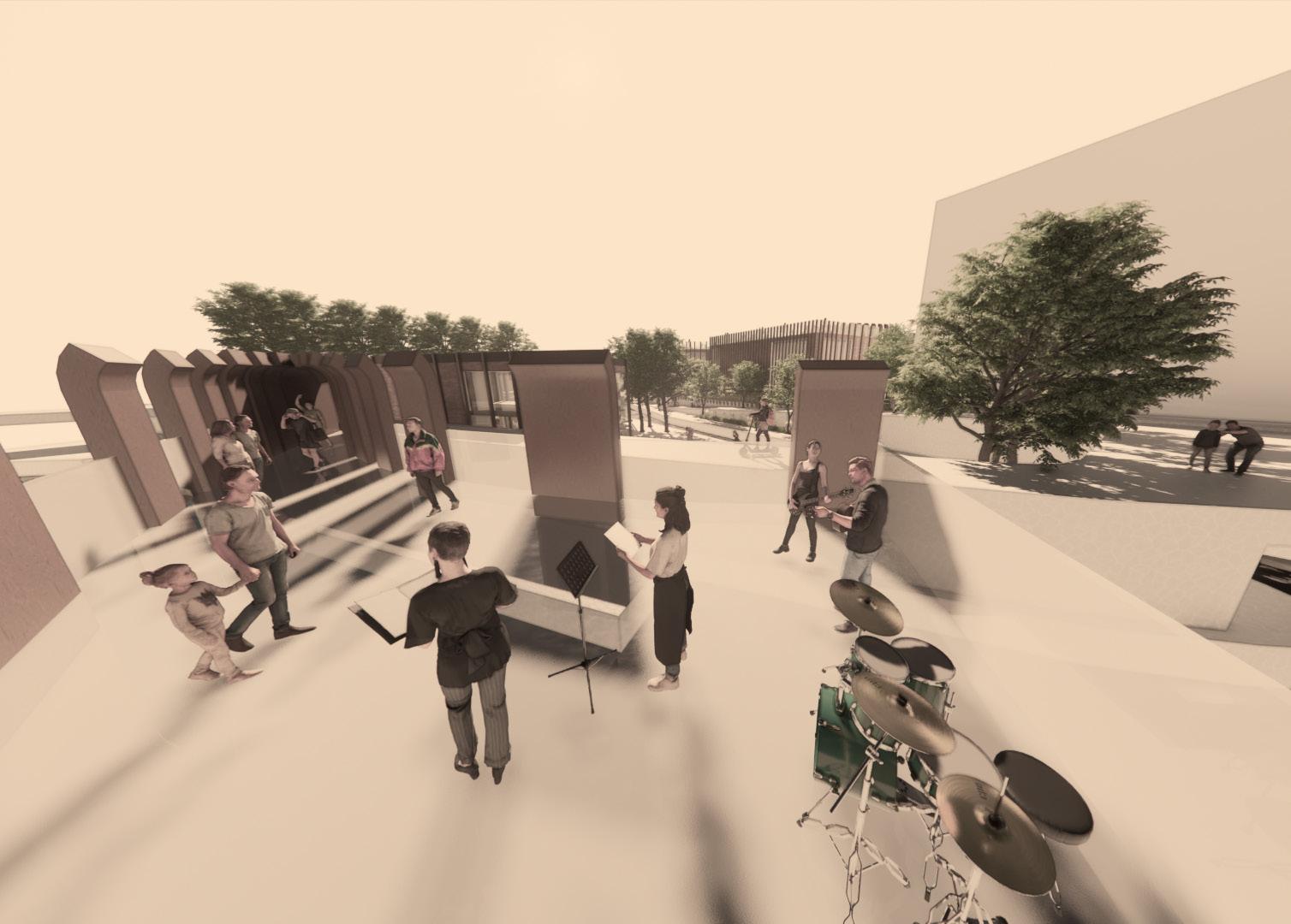
ROOF TERRACES:
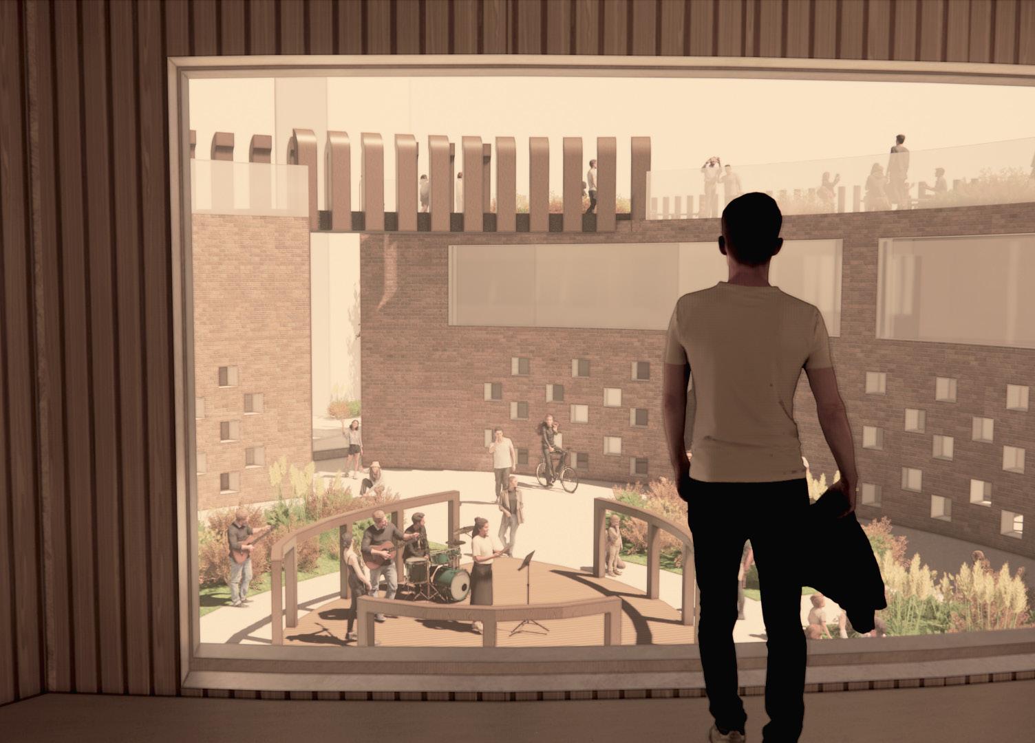
This visual shows the active roof terraces where students and the local community can socialise, enjoy student exhibitions and other outdoor entertainment .
ATRIUM:
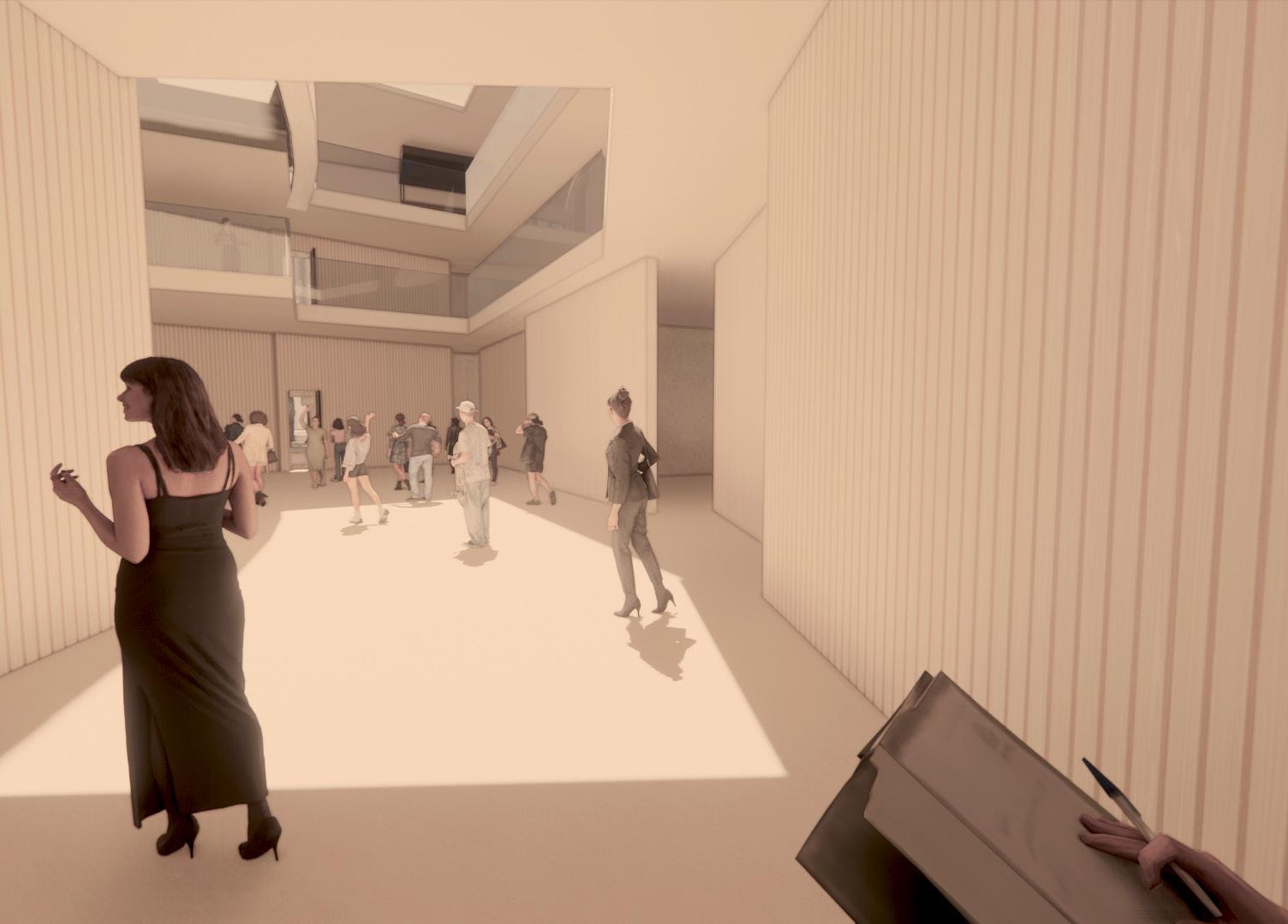
This visual shows the atrium of the music department, which also consists of a light well to bring warmth and daylight into the deep plan space.
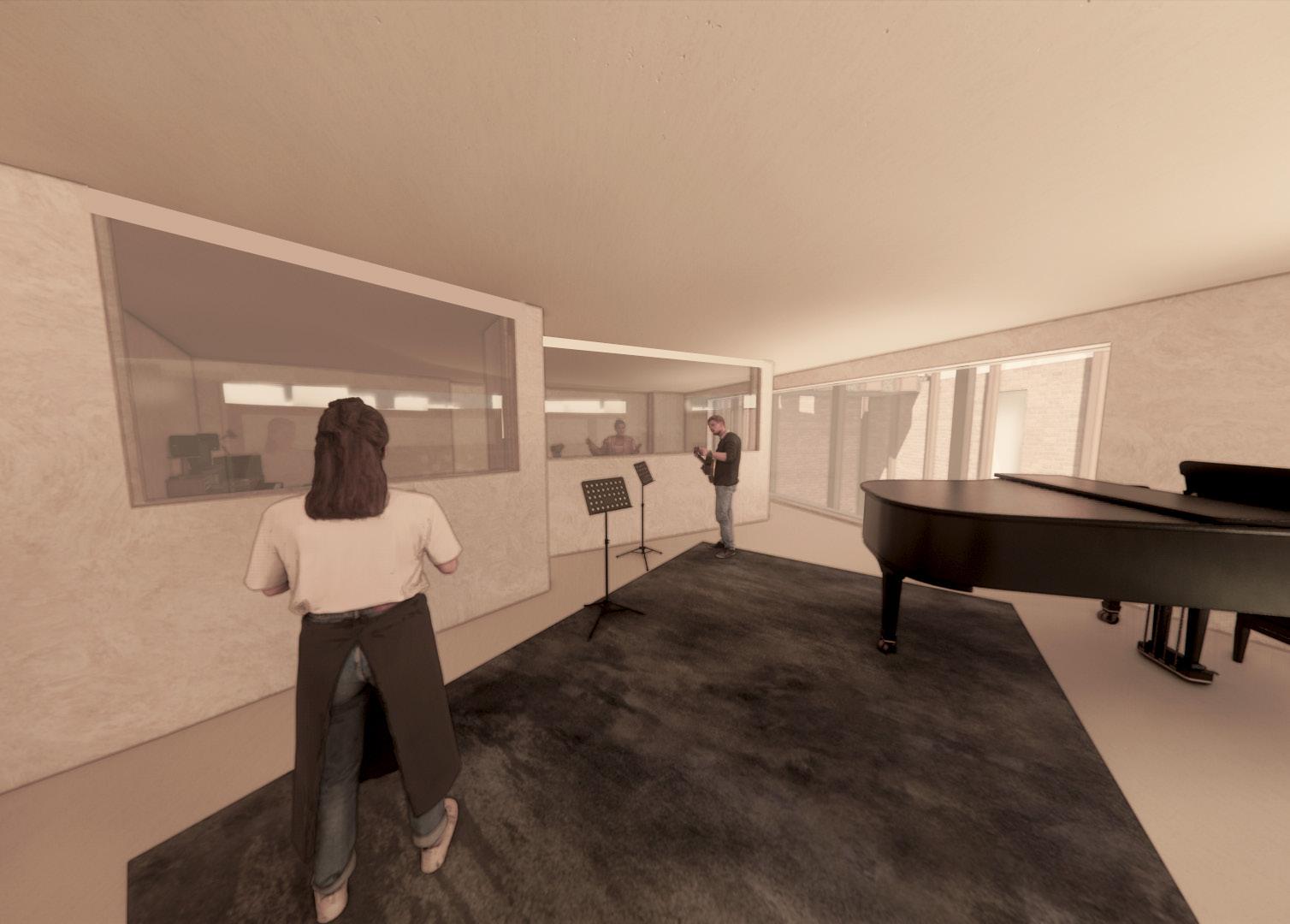
MUSIC STUDIO:
This visual shows an interior view of one of the music studios
8
This visual shows the western approach to the site, leading into the public square.
2. THE PUBLIC SQUARE:
This visual shows the ‘central hub’ of the school, the public square. This is an area where students and the local community are able to come together.
4.
5.
6.
3.
9.
Academic Study
11.
12.
9
7.
VIEW OF PUBLIC SQUARE FROM ATRIUM:
This visual shows a view of the public square from the first floor atrium.
8.
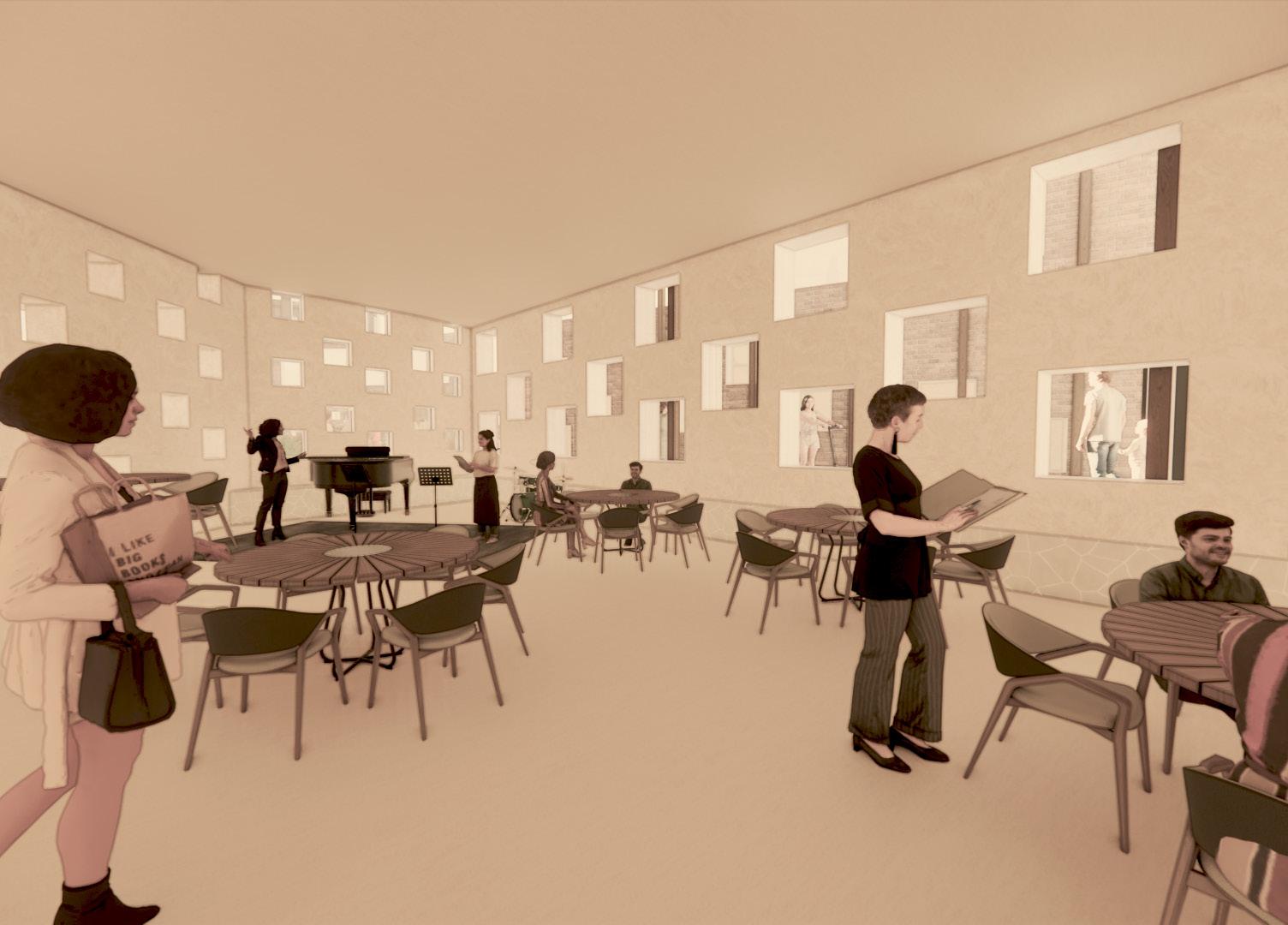
INTERDISCIPLINARY STUDIO/CLASSROOM:
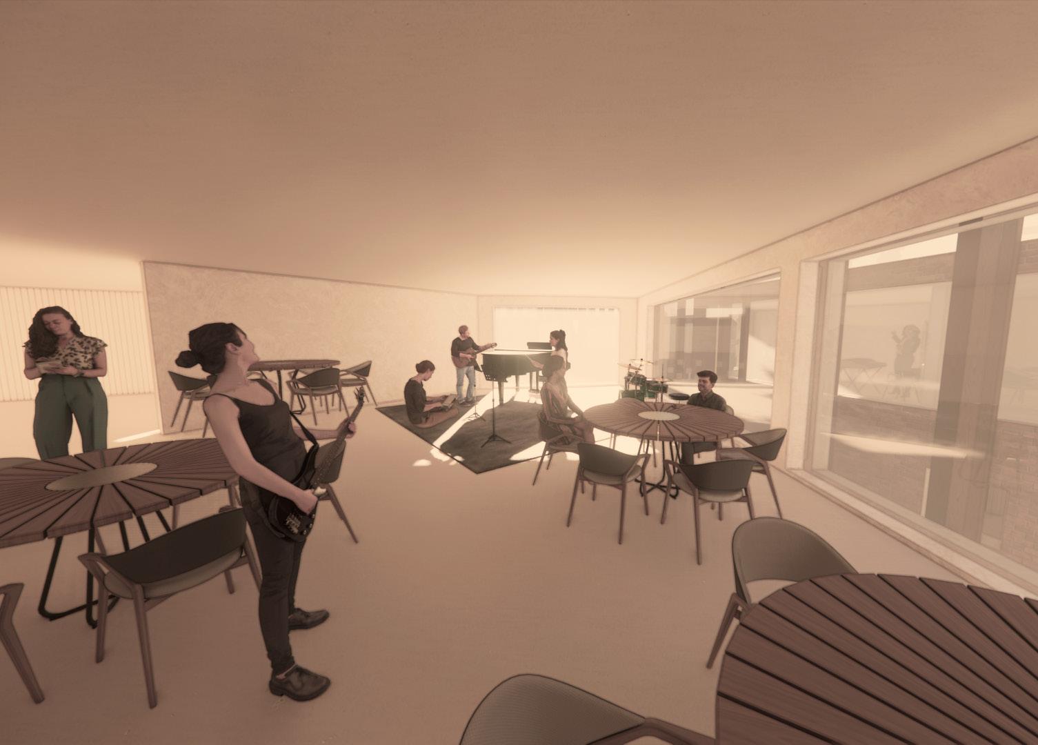
This visual shows a view of an interdisciplinary classroom, that can be used by all departments of the school for seminars, lectures and independent study.
MUSIC CLASSROOM:
This visual shows an interior view of one of the music classrooms.
10.
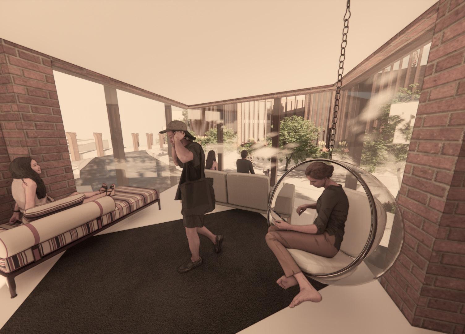
‘DOWNTIME’ (RELAXATION) CENTRE:
This visual shows a view of the ‘downtime’ centre, where students can go to relax and socialise by the water while on campus.
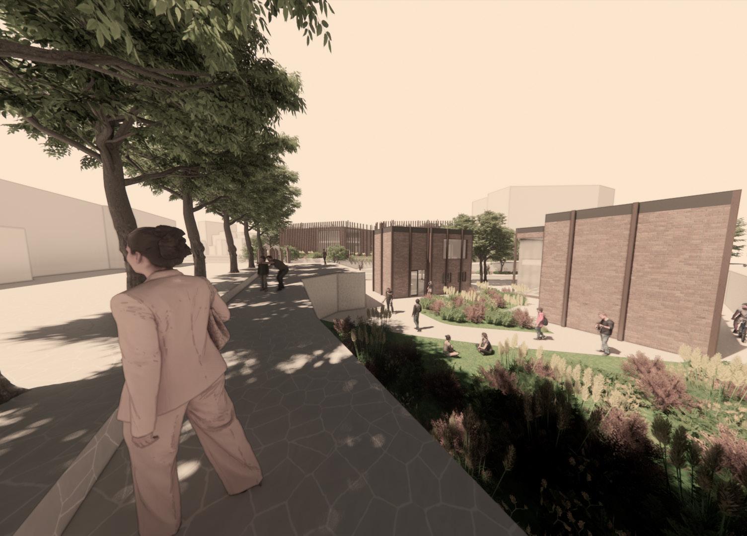
SOUTH-SIDE OF THE SCHOOL:
This visual shows a view of the south-side of the site (where the relaxation centre and water pavilion are located) from the path near the river Trent.
WATER PAVILION::
This visual shows a visual of the water pavilion located at the ‘free’ end of the spiral near the water to symbolise freedom at the end of the journey
Academic Study
Sustainability Strategies:
Solar Panel:
The school sustains itself with south-facing solar panels, a renewable energy source.
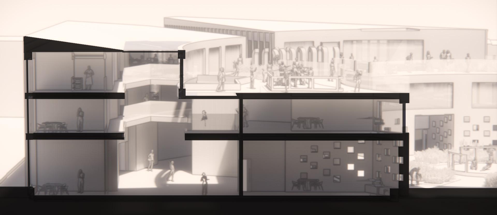
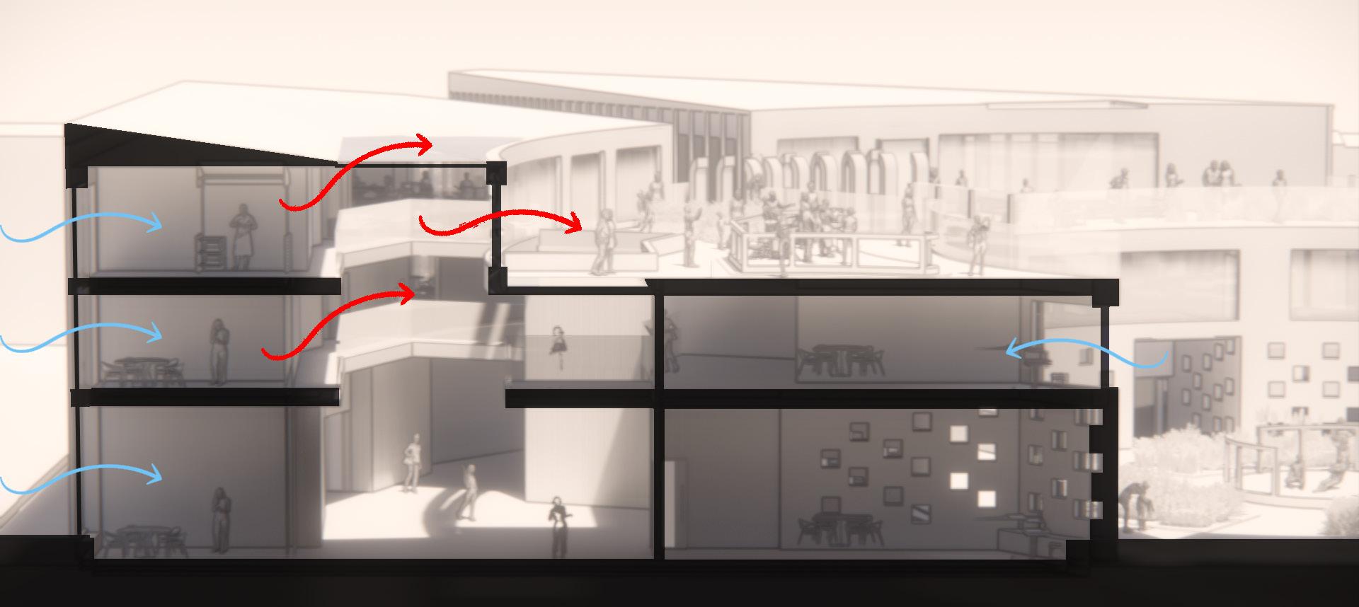
Passive Ventilation & Cooling:
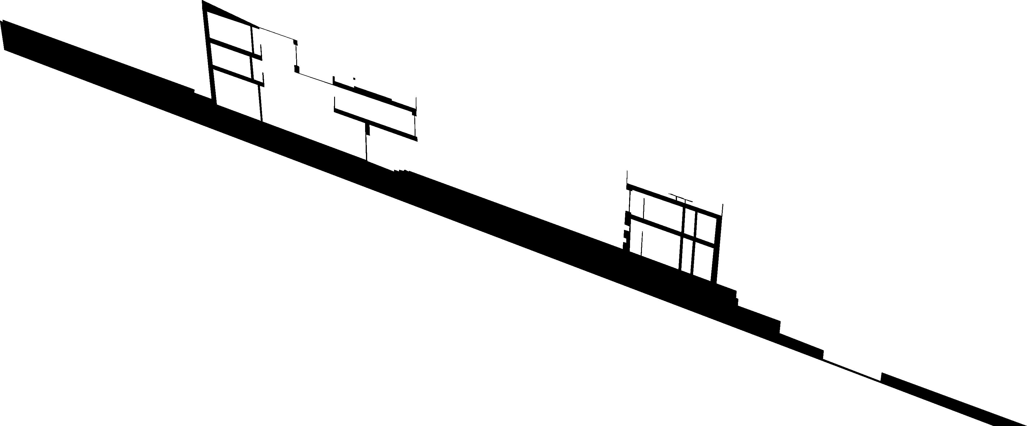
Natural cooling is achieved through a courtyard, large windows, and thermal mass elements like re purposed brick, utilizing prevailing winds and radiant cooling.
Sustainability:
Re purposed brick from the site’s science laboratory reduces embodied energy. Solar panels, passive ventilation, and solar gain align with sustainable principles, reducing reliance on fossil fuels.
Energy Efficiency:
These strategies lower demand for artificial lighting, mechanical cooling, and grid-based electricity, enhancing energy efficiency.
Carbon Footprint:
Integration of solar panels and re-used materials reduces carbon emissions, minimizing reliance on non-renewable resources and lowering the carbon footprint.


10
Academic Study
Structural Development:
- The final grids for the buildings are illustrated on the left.
- By developing a separate grid for each individual building with its own radial point allows me to resolve this issue while creating an internal space that allowed for users to experience the concept of restriction to freedom
- In addition I wanted the scheme to be sustainable My though for this was to use an entire glulam (timber) structure due to the low embodied energy of the material, its durability and renew-ability
- However as the site has flood risks there are issues with this as timber, even when treated, can get water damage.
- Due to the spans and heights of my internal spaces I considered using 300x300 steel beams and columns.
- After conducting an FCBS carbon analysis for my building using steel, brick and concrete for it structural system I concluded to use clt columns and beams to reduce the embodied carbon in my scheme.
However, the part of the structure below the ground level will be concrete.
- This provides flood protection and water resistance for the part of the structure likely to come into contact with water in the event of a flood
- I also went for a concrete pile foundation because of its high load bearing capacity and durability.
- It is also a recommend foundation type for areas prone to water-logging such as the site of my school
Detail A:
Scale - 1:5
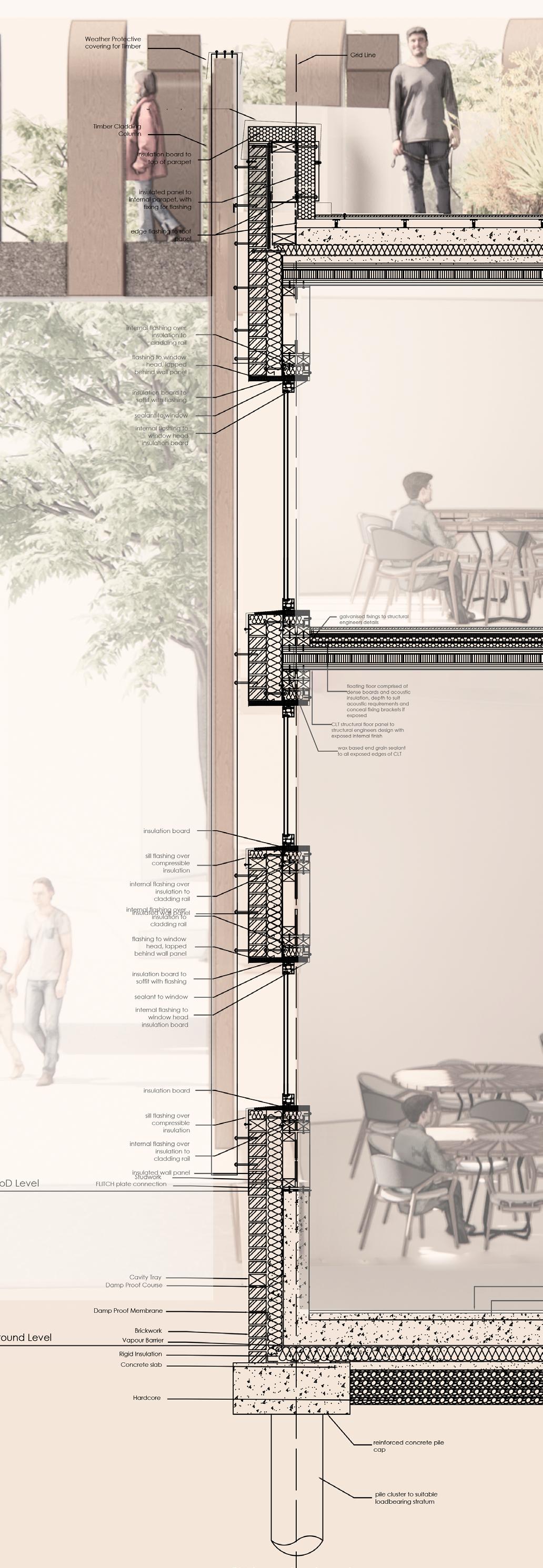
Detail C:
Scale - 1:5
Detail B:
Scale - 1:5
11
reinforced concrete pile cap pile cluster to suitable loadbearing stratum Ground Level FlooD Level Hardcore Concrete slab Damp Proof Membrane Rigid Insulation Vapour Barrier Brickwork Damp Proof Course Studwork FLITCH plate connection well compacted hardcore 50mm sand blinding floor finish 40mm sand cement screed Cavity Tray insulated wall panel internal flashing over insulation to cladding rail sill flashing over compressible insulation insulation board internal flashing over insulation to cladding rail flashing to window head, lapped behind wall panel insulation board to soffit with flashing sealant to window internal flashing to window head insulation board insulated wall panel internal flashing over insulation to cladding rail sill flashing over compressible insulation insulation board CLT structural floor panel to structural engineers design with exposed internal finish wax based end grain sealant to all exposed edges of CLT floating floor comprised of dense boards and acoustic insulation, depth to suit acoustic requirements and conceal fixing brackets exposed galvanised fixings to structural engineers details internal flashing over insulation to cladding rail flashing to window head, lapped behind wall panel insulation board to soffit with flashing sealant to window internal flashing to window head insulation board insulation board to top of parapet insulated panel to internal parapet, with fixing for flashing edge flashing to roof panel flashing over parapet Grid Line Weather Protective covering for Timber Timber Cladding Column internal flashing over insulation to cladding rail flashing to window head, lapped behind wall panel insulation board to soffit with flashing sealant to window internal flashing to window head insulation board insulated wall panel internal flashing over insulation to cladding rail sill flashing over compressible insulation insulation board CLT structural floor panel to structural engineers design with exposed internal finish wax based end grain sealant to all exposed edges of CLT floating floor comprised of dense boards and acoustic insulation, depth to suit acoustic requirements and conceal fixing brackets exposed galvanised fixings to structural engineers details internal flashing over insulation to cladding rail flashing to window head, lapped behind wall panel insulation board to soffit with flashing sealant to window internal flashing to window head insulation board insulated wall panel internal flashing over insulation to cladding rail sill flashing over compressible insulation insulation board CLT structural floor panel to structural engineers design with exposed internal finish wax based end grain sealant to all exposed edges of CLT floating floor comprised of dense boards and acoustic insulation, depth to suit acoustic requirements and conceal fixing brackets exposed galvanised fixings to structural engineers details Detail C: Scale - 1:5 Detail B: Scale - 1:5 Detail A: Scale - 1:5
Personal Project
Pulborough Pier
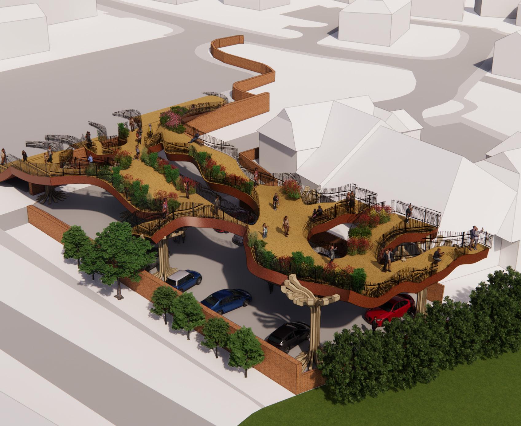
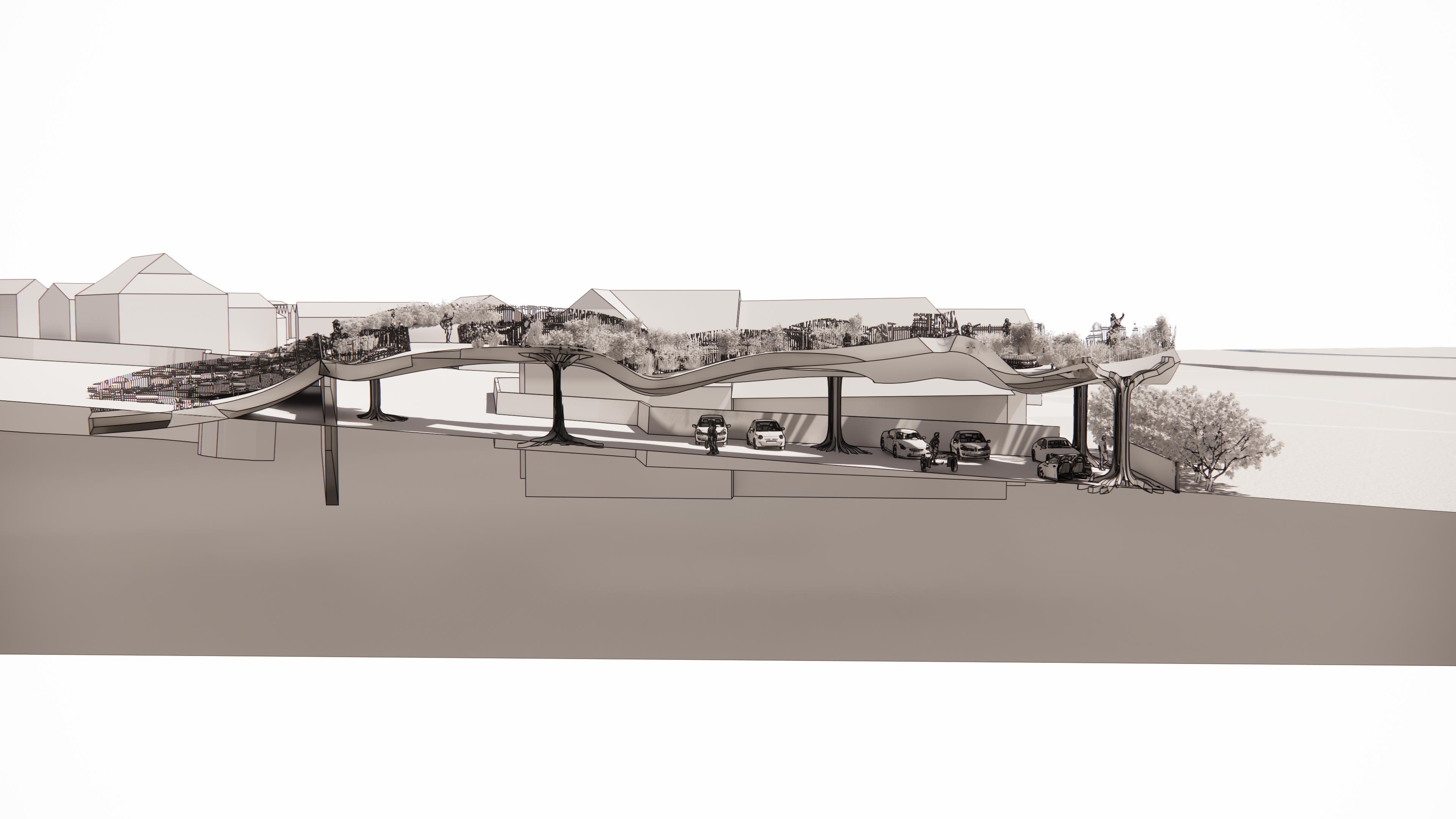
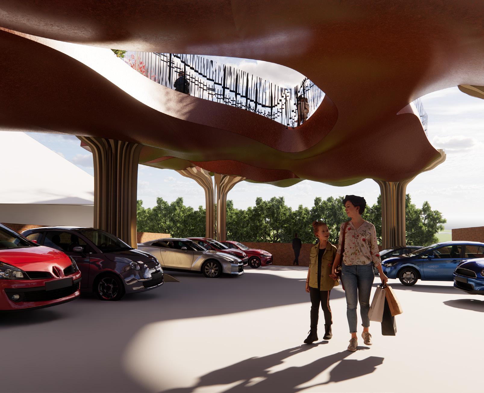
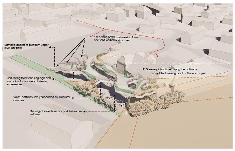
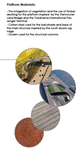
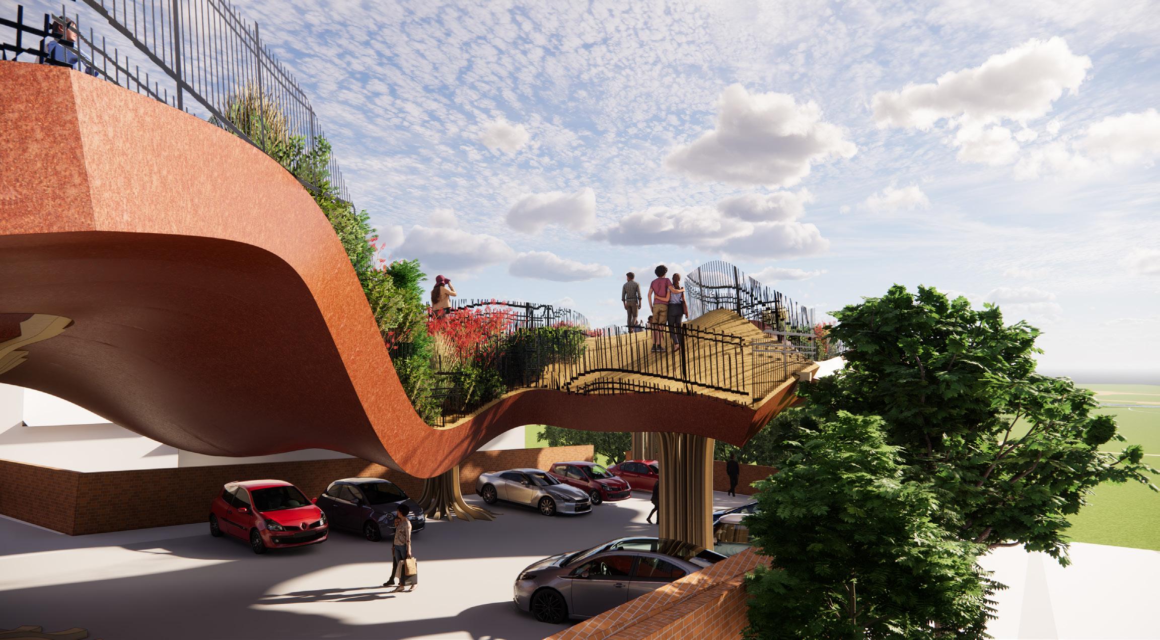
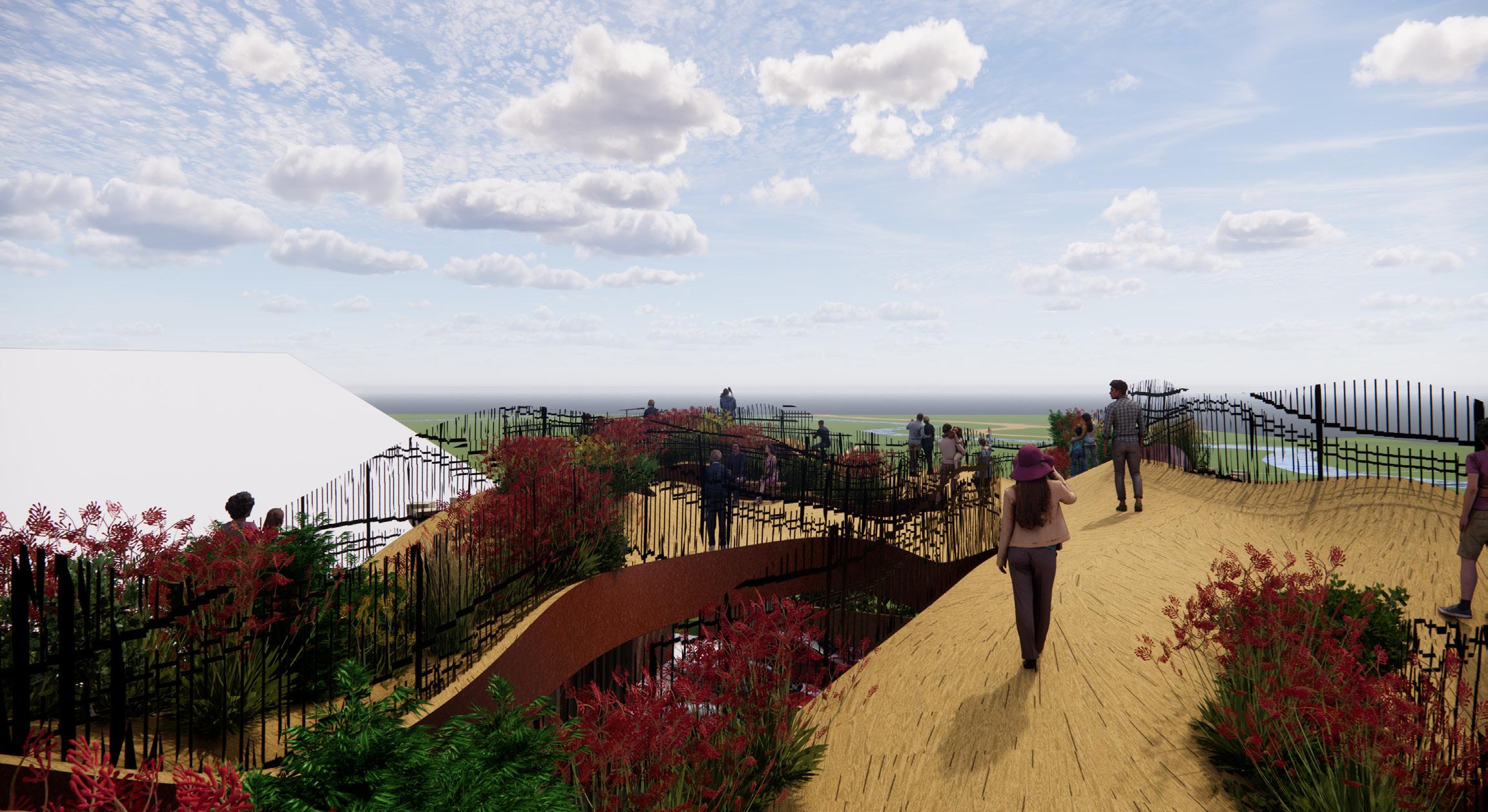
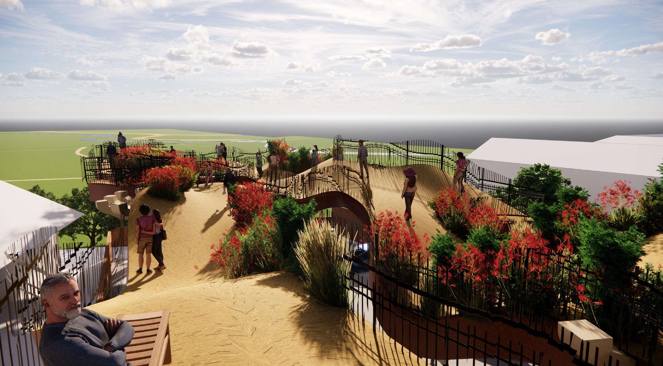
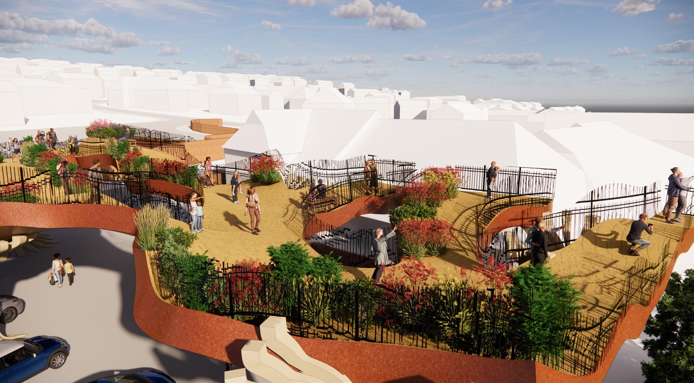
Inspired by the organic forms of the South Downs signage and the undulating topography of Pulborough’s meadows, the design features a striking, naturalistic structure. Utilising corten steel and timber, materials synonymous with the South Downs region, the platform rises elegantly on ‘stilts’ resembling tree-like columns. This design choice not only reinforces the connection to nature but also allows for continued use of the space as a car park, with the platform suspended above.
Lightwells integrated into the structure ensure ample natural light penetrates the lower level, preserving visibility and ambiance. Biodiversity is promoted through the inclusion of vegetation on the platform, mirroring the natural flora of the surrounding area. At the end of the platform, the ideal viewing point offers visitors a breathtaking panorama of Pulborough’s scenic vistas. .
A key aspect of the design is its commitment to sustainability. Solar panels integrated into the platform enable the generation of electricity to power lighting and other amenities. This self-sufficient energy solution not only reduces environmental impact but also contributes to the overall sustainability of the project.
The Pulborough Viewing Platform represents more than just an architectural structure; it embodies a vision for sustainable development, community engagement, and appreciation of natural beauty. As an aspiring sustainable designer, I firmly believe in the importance of integrating environmental considerations into every facet of my work. Through thoughtful design and integration with the surrounding environment, the project seeks to enrich the lives of residents and visitors alike, while fostering a deeper connection to the unique landscapes of Pulborough. My dedication to sustainability drives me to create spaces that not only enhance the built environment but also prioritize the well-being of both people and the planet.
12
Personal Project
13
Practice Experience
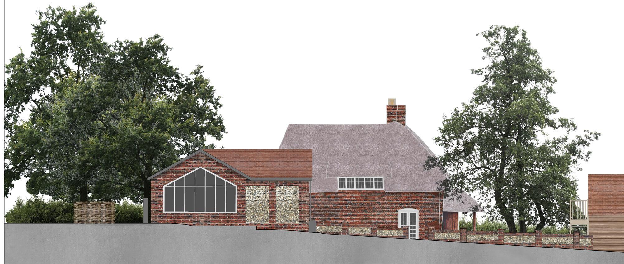
Old Manor Cottage
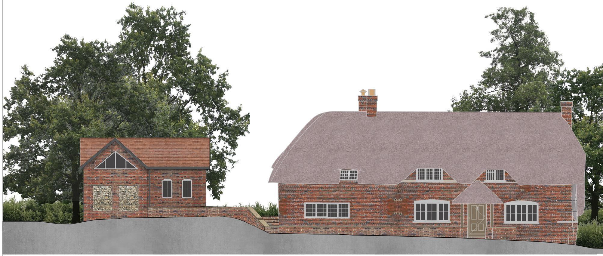
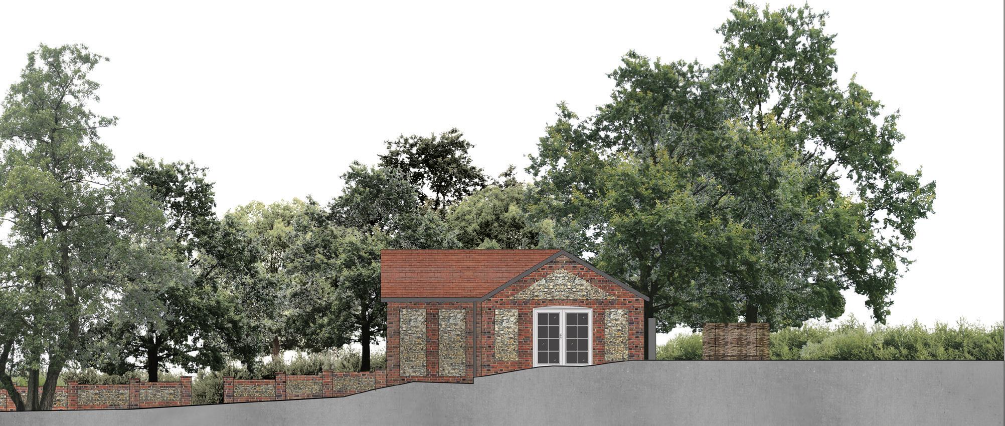
The Project:
Redevelopment of existing outbuildings
My Role:
Responsible for developing both existing and proposed drawings using site survey information. Collaborating closely with the team, I ensured that our proposal met the specific needs and desires of our client. Additionally, I contributed to creating Photoshop elevations of our proposal, which were prominently featured in our design and access statement for the project.
14
- South West Elevetation
Left
- South East Right - North East
Front
m EX-FFL 113.499 EX-FFL 113.012 113.210 L0 01 STORAGE GIA 14.6m² 1 2 3 5 6 any other party reported immediately. documents and other accepted good practice (e.g. Quality assured job 1:50 @A3 @A1 700 T01 r 6302.5 Surface mounted track light with switch and PIR RIGHT ELEVATION figured dimensions only. Queries directed Architect. drawings for construction unless explicitly marked Certificate stamped and independently certified otherwise show 703 T01 r LEFT SOUTH WEST RIGHT NORTH EAST Timber cladding Timber cladding Roof tiles match Outbuilding 01 Developer Range colour medium Timber cladding enclose stair creating store L1 00 FIRST FLOOR STORAGE GIA 51.7m² 10 11 EX-FFL 113.499 m EX-FFL 113.012 113.210 any other party reported immediately. documents and other accepted good practice (e.g. Quality assured job 1:50 @A3 @A1 701 T01 r Capped drainage and water supply points spot lights Use figured dimensions only. Queries directed the Architect. drawings are construction unless explicitly marked this Certificate stamped and independently certified otherwise show 702 T01 r FRONT NORTH WEST REAR SOUTH WEST Crevice feature behind cladding Roof tiles match Outbuilding Larch pressure treated Timber cladding Outbuilding 1(Photoshop Elevations) Garage (Plans & Elevations)
Practice Experience
50 Notting Hill Gate
The Project:
Transforming an old Lloyds Bank Building into a Food & Beverage scheme
My Role:
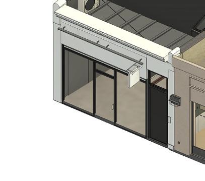
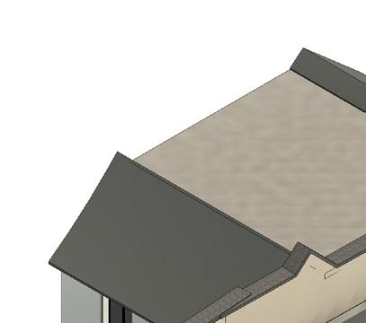
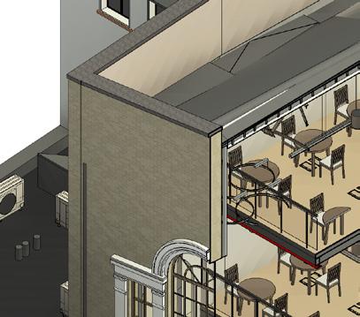
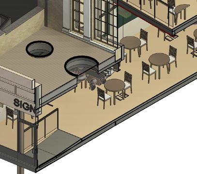
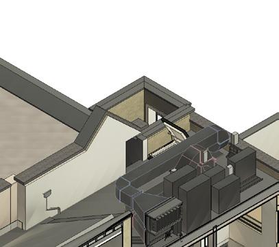
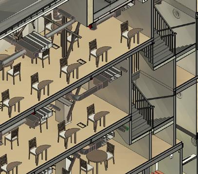
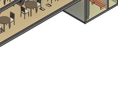
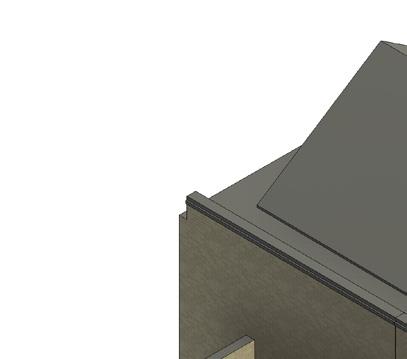
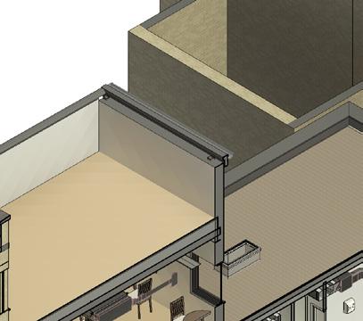
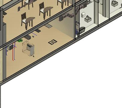
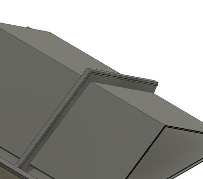
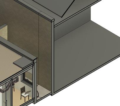
I was responsible for converting the existing Revit model into our proposed restaurant scheme, working closely with structural engineers and utilising site survey information. Additionally, I curated a comprehensive document showcasing our restaurant proposal to the client, integrating concept images, visuals and technical




15 A B 3 Job Number Job Title Drawing Number Revision Status PLANNING Scale Drawing Title www.ra-l.com 16 Iliffe Yard London SE17 3QA info@ra-l.com ©ARCHITECT'S COPYRIGHT RETAINED GENERAL NOTES All dimensions be checked on site. Use figured dimensions only. Queries to be directed to the Architect. Refer to Structural Engineer's drawings for details relating structure Any discrepancies between the Architect's drawings and those by any other party be reported immediately. All drawings are not for construction unless explicitly marked for this purpose. GENERAL NOTES ON MATERIALS Materials to comply with appropriate British Standards Agrement Certificate stamped and independently certified or otherwise show their suitability. Materials should be accordanc with BS8000 series of documents and other accepted good practice (e.g. Quality assured to ISO9000). 1 100 T02 A020 50 Notting Hill Gate A020-012 Proposed Basement Plan 1 100 Proposed Basement 1 0 SCALE 1: 3 m 100 N Staff Room Store RevDescriptionDate T01Tender Issue 05.05.23 T02Tender IssueNOTE: ALL FURNITURE SHOWN IS INDICATIVE A B 4 3 6 Internal 1:12 ramp access from entrance street evel Flat level access Kitchen Riser Location Refer Structural Engineer's drawings for deta relating structure drawings are construction unless explicitly marked this purpose. their suitability. Materials should accordanc ISO9000). N 100 Proposed Ground Raised Access Floor 1 KEY RevDescriptionDate T02Tender IssueIS INDICATIVE A B 5 4 3 1 6 Railing for protection against fall Roof hatch with retractable ladder provide roof access Railing for protection against fall Riser Location Job Title N 100 Proposed Second Floor 1 A020-019 4 3 2 6 Selecta glaze S40 with 24mm Enhanced Thermal Sealed Unit and 100mm cavity. Spec 2.20. Riser Location Job Number Job Title Drawing Number Drawing Title London SE17 3QA info@ra-l.com Refer Structural Engineer's drawings deta relating structure drawings construction unless explicitly marked for their suitability. Materials should accordanc ISO9000). 100 T02 A020 Notting Hill Gate A020-014 Proposed First Floor Plan 100 Proposed First Floor 1 N KEY RevDescriptionDateNOTE: ALL FURNITURE SHOWN IS INDICATIVE Ground floor facade to have concrete tiles outer skin removed Portland Stone, colour -off white Timber stall riser painted black Window glazing with timber frame painted black Recessed zone for signage -Timber painted black 150mm Projecting Portland Stone cornice, colour -off white Timber door painted black 150mm Projecting Portland Stone Corbel, colour -off white 500 500 150mm Projecting Portland Stone cornice, colour -off white 353 403 150 871 ©ARCHITECT'S COPYRIGHT RETAINED dimensions checked site. Use figured dimensions only. Queries be direc Refer to Structural Engineer's drawings for deta Any discrepancies between the Architect's drawin any other party be reported immediately. drawings are not construction unless explicitly marked for this Certificate stamped and independently certified their suitability. Materials should be accordanc ISO9000). RevDescriptionDate P01Planning Issue P02Planning Issue T01Tender Issue T02Tender Issue P03Planning Issue P04Planning Issue P05Planning Issue P06Planning Issue KEY Demolition 1 50 Existing Front Elevation Shopfront 1 50 Proposed Front Elevation Shopfront 2 4 3 2 6 Railing for protection against fall Job Title Drawing Number Drawing Title London SE17 3QA Refer Structural Engineer's drawings deta relating structure drawings construction unless explicitly marked for their suitability. Materials should accordanc 100 A020 Notting Hill Gate A020-016 Proposed Attic Plan 100 Proposed Attic Plan 1 N RevDescriptionDate Railing for protection against fall Roof hatch with retractable ladder to provide roof Proposed Basement Plan Proposed Ground Floor Plan Proposed Second Floor Plan Proposed First Floor Plan Proposed Front Elevation Proposed Roof Plan
drawings
our proposal Proposed Section Axonometric Proposed Axonometric 1
of
00 W.22
00 W.23
00 W.24
ED-00-02 15 M TRAVEL
A B C D E
ID-00-12 ID-00-02
83 m² OPEN PLAN LIVING SPACE
74 m² KITCHEN 18 m²
ID-00-08
8 M TRAVEL
DN
Practice Experience DN DN
ID-00-05 ID-00-06
ID-00-07
©ARCHITECT'S COPYRIGHT RETAINED GENERAL NOTES dimensions be checked on site. Use figured dimensions only. Queries to be directed to the Architect. Refer to Structural Engineer's drawings for deta relating structure Any discrepancies between the Architect's drawings and those by any other party to be reported immediately. drawings are not for construction unless explicitly marked for this GENERAL NOTES ON MATERIALS Materials comply with appropriate British Standards Agrement Certificate stamped and independently certified otherwise to show their suitability. Materials should be in accordanc with BS8000 series documents and other accepted good practice (e.g. Quality assured ISO9000). RevDescriptionDate T01Drawing Issue 26.03.22 T02Fire Curtain added 20.04.22 C01Construction Issue 17.05.22 C02Construction Issue 22.06.22 C03Construction Issue 28.07.23 C04Construction Issue 04.01.24 C05Construction Issue 29.02.24 30 MINUTE FIRE SMOKE CURTAIN FIRE STRATEGY KEY 60 MINUTE FIRE SMOKE CURTAIN 30 MINUTES FIRE RATED DRY RISER MINUTE FIRE DOOR MINUTE SMOKE SEALED DOOR
1 2 3 5 6
The Project:
Development of a 2 storey House
00 W.14
00 W.13
00 W.12
00 W.11
00 W.10
00 W.21 00 W.1 00 W.2 00 W.3
00 W.4 00 W.5 00 W.6 00 W.7 00 W.8 00 W.9 4
10 m² UTLITY m² PLAYROOM m² WC 37 m² CINEMA ROOM 70 m² POOL ROOM
00 W.20
ID-00-01 ED-00-03
My Role:
ID-00-03 ID-00-04 ID-00-10
m² 19 m² HALL POOL PLANT
ID-00-13 ID-00-09 ID-00-11
13.9 M TRAVEL 11.5 M TRAVEL 16.3 M TRAVEL 5.1 M TRAVEL 10.8 M TRAVEL
38 m² GARAGE
F
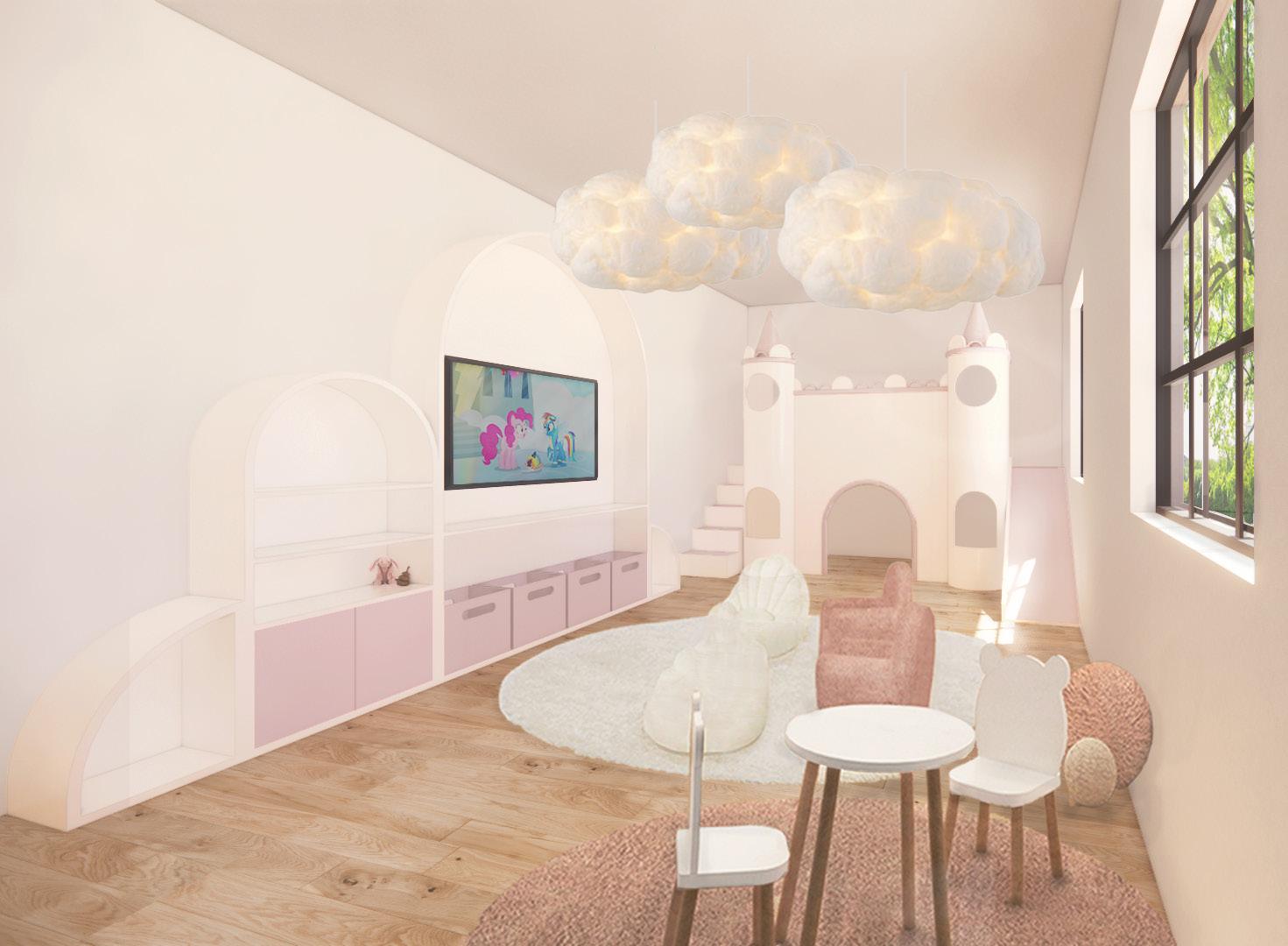
clear vision of the proposed playcastle.
the client with
FIRE ESCAPE Ground Floor Plan


ANTIQUE BRASS DOOR THRESHOLD STRIP Drawing Number







Job Number Job Title Drawing Number Revision Status CONSTRUCTION Scale Drawing Title www.ra-l.com 16 Iliffe Yard London SE17 3QA rory@ra-l.com ©ARCHITECT'S COPYRIGHT RETAINED Use figured dimensions only. Queries be directed to the Architect. Refer to Structural Engineer's drawings for deta relating to structure Any discrepancies between the Architect's drawings and those by for construction unless explicitly marked this purpose. Materials comply with appropriate British Standards Agrement Certificate stamped and independently certified otherwise to show their suitability. Materials should be accordanc documents and other accepted good practice (e.g. Quality assured 20 C01 A011 11 Withdean Road A011-322 Playroom Rendered Interior Elevations RevDescriptionDate C01Castle playhouse added to 09.01.24 Playroom Elevation A Playroom Elevation B 2 Playroom Elevation C 1 20 Playroom Elevation D 4 ted to the Architect. relating to structure Any discrepancies between the Architect's drawings and those by any other party to be reported immediately. for construction unless explicitly marked for this purpose. GENERAL NOTES ON MATERIALS Materials comply with appropriate British Standards Agrement Certificate stamped and independently certified or otherwise to show their suitability. Materials should be in accordanc with BS8000 series documents and other accepted good practice (e.g. Quality assured ISO9000). RevDescriptionDate C01Castle playhouse added to playroom 09.01.24 1 20 Playroom Elevation A 1 1 20 Playroom Elevation C 3 Playroom Visual 1 20 Playroom Elevation A 1 1 20 Playroom Elevation B 2 1 20 Playroom 3 1 20 Playroom 4 Job Number Job Title Drawing Number Revision Status CONSTRUCTION Scale Drawing Title www.ra-l.com 16 Iliffe Yard London SE17 3QA rory@ra-l.com ©ARCHITECT'S COPYRIGHT RETAINED GENERAL NOTES All dimensions be checked on site. Use figured dimensions only. Queries to be direc Refer Structural Engineer's drawings for details relating structure Any discrepancies between the Architect's drawin and those any other party be reported immediately. All drawings are not for construction unless explicitly marked for this Materials to comply with appropriate British Standards or Agrement Certificate stamped and independently certified or their suitability. Materials should be accordanc with BS8000 series of documents and other accepted good practice (e.g. Quality assured to ISO9000). 20 C01 A011 11 Withdean Road A011-322 Playroom Rendered Interior Elevations RevDescriptionDate C01Castle playhouse added to playroom 09.01.24 1 20 Playroom Elevation A 1 1 20 Playroom Elevation B 2 1 20 Playroom Elevation C 3 1 20 Playroom Elevation D 4
16
Withdean Road D W DN DN
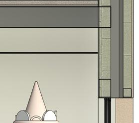
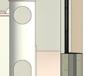
My role in this project involved updating our Revit model and drawings for issuance during the construction process. I was tasjed with specific focus on developing a proposal for a playcastle in the kids’ playroom. Collaborating closely with the interior designer, we conceptualized the design and I translated it into a detailed revit family, which i then integrated into our reevit model. Additionally, I developed a compelling visual of the space’s potential using Photoshop, providing
a
Playroom Rendered Elevations
Retention of air duct and 2 new emergency access lights within the front lightwell
Existing ramp up to raised floor Wooden balustrade behind bar stools Existing step up to raised floor Existing column retained Free standing coat cupboard and reception desk joinery Retention of the reconfigured seating booths either end of the banquette seating into DJ pulpits Retention of the illuminated signage within the windows New menu board stand to be placed within the courtyard
Retention of 3 AC casettes
Existing fire escape stair Existing fire escape window retained Retention of extract duct within store Retention of partial height joinery to match height of balustrade
Practice Experience LIFT SERVICE LIFT job title drawing title drawing no. revision
GENERAL NOTES Use figured dimensions only. Queries directed to the Architect. Refer Structural Engineer's drawings for details relating structure Any discrepancies between the Architect's drawings and those by any other party to be reported immediately. All drawings are not for construction unless explicitly marked for this purpose. GENERAL NOTES ON MATERIALS Materials comply with appropriate British Standards or Agrement Certificate stamped and independently certified otherwise show their suitability. Materials should be accordance with BS8000 series documents and other accepted good practice (e.g. Quality assured ISO9000).
The Project:
Listed Building Consent for grade ii* listed church
My Role:
Line of existing mezzanine above 2 N.O. Existing dumbwaiter shafts to lower ground floor kitchen Retention of the stage and DJ pulpits Fire escape stair Existing railings retained
Retention of lighting rigs either side of the alter
Retention of reconfigured bar and kitchen Retention of the speakers and new light fittings and projectors Free standing planters to enclose refuse bins and kegs
Existing old york slabs to be lifted and saved. New bedding laid and a mix of existing and close matching reclaimed traditional york stone slabs relaid
ARCHITECT'S COPYRIGHT RETAINED status job no. 10m 1:100 @A3 1:50 @A1
Existing glass balustrade retained to mezzanine edge 6 N.O. Existing ceiling hooks Existing reredos retained
fixed
Existing reredos retained Retention of wing artwork Ground Floor Plan job title
date amendment
Monmouth Planning Ltd 38a Monmouth Street London WC2H 9EP info@monmouthplanning.co.uk
9a St Thomas Street A592
INFORMATION
Use figured dimensions only. Queries directed Architect. Refer Structural Engineer's drawings for details relating documents and other accepted good practice (e.g. Quality assured ISO9000).
London SE1 9RY GROUND FLOOR 003 P01
Retention of partial height service counter Existing stair Retention of speakers Retention of new lighting P01 22.02.24 DRAFT SET First Floor Plan
GENERAL NOTES All dimensions checked site. Use figured dimensions only. Queries be directed to the Architect. Refer to Structural Engineer's drawings for details relating Any discrepancies between the Architect's drawings and those by any other party to be reported immediately. drawings are not for construction unless explicitly marked for this purpose. Materials comply with appropriate British Standards or Agrement Certificate stamped and independently certified otherwise show their suitability. Materials should be in accordance with BS8000 series documents and other accepted good practice (e.g. Quality assured ISO9000).
job title
rev date amendment
Monmouth Planning Ltd 38a Monmouth Street T: 020 7042 0410 E: info@monmouthplanning.co.uk
ARCHITECT'S COPYRIGHT RETAINED 9a St Thomas Street London SE1 9RY
ARCHITECT'S COPYRIGHT RETAINED 5m 1:50 @A3 1:25 @A1 008 P01
New signage on the stone plaque
Retention of the illuminated signage within the windows New signage to the railing New menu board stand to be placed within the courtyard
Monmouth Planning Ltd job title
Section D Front Elevation
Retention of hanging sign Free standing planters to enclose refuse bins and kegs
Monmouth 38a Monmouth Street WC2H 9EP info@monmouthplanning.co.uk
GENERAL NOTES dimensions checked Use figured dimensions Refer Structural Engineer's structure Any discrepancies between any other party reported drawings are not GENERAL NOTES ON Materials comply with Certificate stamped and their suitability. Materials documents and other ISO9000). 10m 1:100 @A3 1:50
17
Amazing Grace - Site Experience FFL +5.20
I was responsible for updating existing drawings to accurately reflect the current state of the building and proposed changes following a comprehensive site visit. I took measurements of proposed
elements, including the bar and stage, as well as other desired modifications outlined by the client. I included detailed notes outlining all modifications, providing clarity for the planning application process.
The Project:
Transforming an old Lloyds Bank Building into a white box scheme
My Role:
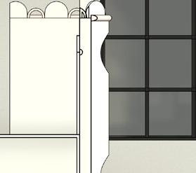
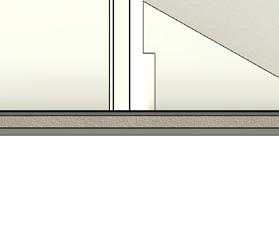
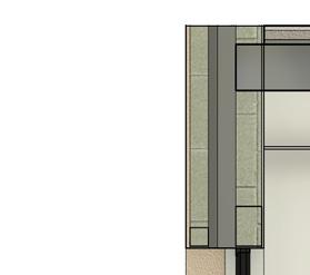
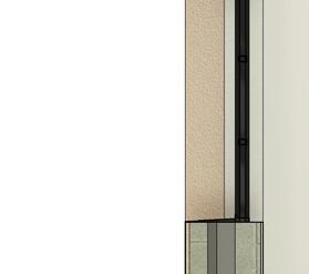
Throughout the construction process of this project I have been responsible for drawing roof details and issuing them to the contractor. Examples below:
18 Technical Studies Construction Details Ground Floor 27600 First Floor 30700 Basement 25270 Second Floor 34022 Attic 37000 Roof 39241 1 A020-251 2 A020-251 1 A020-252 2 A020-252 3 A020-252 2656 2718 2732 2828 2643 2543 3000 1 A020-021 Ground Floor 27600 First Floor 30700 Basement 25270 34022 0 SCALE 1: 2 1 1 100 1 : 100 Proposed Section A 2 1 : 100 Demolition Section A 1 Roof 4 Roof 3 Roof 5 Roof 1 Roof 2 148 22 170 150 500 13 280 50 10 25 ©ARCHITECT'S COPYRIGHT RETAINED GENERAL NOTES All dimensions checked on site. Use figured dimensions only. Queries to be directed the Architect. Refer Structural Engineer's drawings deta relating structure Any discrepancies between the Architect's drawings and those by any other party be reported immediately. All drawings are not for construction unless explicitly marked for this GENERAL NOTES ON MATERIALS Materials comply with appropriate British Standards Agrement Certificate stamped and independently certified their suitability. Materials should accordanc with BS8000 series of documents and other accepted good practice (e.g. Quality assured to ISO9000). RevDescriptionDate T01Tender Issue 22.12.23 C01Construction Issue 02.02.24 C02Construction Issue 26.02.24 1 5 Roof detail 1 1 Timber Joist Plywood decking to 1:60 fall Kingspan Thermaroof TR27double layered (80mm 90mm) Single ply membrane 12.5mm Plasterboard Vapour Barrier Single ply membrane 1 5 Roof Detail 3 3 Concrete Slab Kingspan 280mm Greenguard GG300 (Inverted Roofingdouble layered) 500x500mm Concrete paving slabs Liquid applied waterproofing Pedestals Geotextile layer 12.5mm Plasterboard Screed to 1:100 fall 148 22 170 150 13 150 500 13 280 50 10 150 50 38 25 13 Job Number Job Title Status TENDER Scale Drawing Title GENERAL NOTES All dimensions be checked Use figured dimensions Refer Structural Engineer's Any discrepancies between any other party be reported All drawings are not for GENERAL NOTES ON Materials to comply with Certificate stamped and their suitability. Materials of documents and other to ISO9000). A011 50 Notting Hill Gate Roof details RevDescriptionDate T01Tender C01Construction C02Construction 1 5 Roof detail 1 1 Timber Joist Plywood decking to 1:60 fall Kingspan Thermaroof TR27double layered (80mm + 90mm) Single ply membrane 12.5mm Plasterboard Vapour Barrier 1 5 Roof Detail 2 2 Concrete slab Kingspan Thermataper TT47 (150-250mm) to 1:60 fall Single ply membrane 1 5 Roof Detail 3 3 Concrete Slab Kingspan 280mm Greenguard GG300 (Inverted Roofingdouble layered) 500x500mm Concrete paving slabs Liquid applied waterproofing Pedestals 1 5 Roof Detail 4 4 Kingspan Kooltherm K118 37.5mm (12.5mm plasterboard internal finish) Kingspan 150mm Kooltherm K107 Insulation - (Between timber rafters) Kingspan nilvent breathable membrane Roof tiles replaced to match existing Geotextile layer Vapour Barrier 12.5mm Plasterboard 12.5mm Plasterboard Cross battens Screed to 1:100 fall
Roof Detail 1 500 All dimensions to be checked site. Use figured dimensions only. Queries directed the Architect. Refer to Structural Engineer's drawings for details relating structure Any discrepancies between the Architect's drawin and those by any other party be reported immediately. All drawings are for construction unless explicitly marked this purpose. GENERAL NOTES ON MATERIALS Materials comply with appropriate British Standards or Agrement Certificate stamped and independently certified their suitability. Materials should be in accordanc with BS8000 series documents and other accepted good practice (e.g. Quality assured ISO9000). RevDescriptionDate T01Tender Issue 22.12.23 C01Construction Issue 02.02.24 C02Construction Issue 26.02.24 1 5 Roof detail 1 1 Timber Joist Plywood decking to 1:60 fall Kingspan Thermaroof TR27double layered (80mm 90mm) Single ply membrane 12.5mm Plasterboard Vapour Barrier 1 5 Roof Detail 3 3 Concrete Slab Kingspan 280mm Greenguard GG300 (Inverted Roofingdouble layered) 500x500mm Concrete paving slabs Liquid applied waterproofing Pedestals Geotextile layer 12.5mm Plasterboard Screed to 1:100 fall Roof Detail 3 148 22 170 150 13 150 500 13 280 50 10 150 50 38 25 13 Job Title Drawing Title www.ra-l.com 16 Iliffe Yard London SE17 3QA e info@ra-l.com ©ARCHITECT'S COPYRIGHT RETAINED GENERAL NOTES All dimensions be checked on site. Use figured dimensions only. Queries be directed to the Architect. Refer to Structural Engineer's drawings for details relating to structure Any discrepancies between the Architect's drawings and those by any other party to be reported immediately. All drawings are not for construction unless explicitly marked for this purpose. GENERAL NOTES ON MATERIALS Materials to comply with appropriate British Standards Agrement Certificate stamped and independently certified otherwise show their suitability. Materials should be in accordanc with BS8000 series documents and other accepted good practice (e.g. Quality assured ISO9000). 50 Notting Hill Gate Roof details RevDescriptionDate T01Tender Issue 22.12.23 C01Construction Issue 02.02.24 C02Construction Issue 26.02.24 1 5 Roof detail 1 1 Timber Joist Plywood decking to 1:60 fall Kingspan Thermaroof TR27double layered (80mm + 90mm) Single ply membrane 12.5mm Plasterboard Vapour Barrier 1 5 Roof Detail 2 2 Concrete slab Kingspan Thermataper TT47 (150-250mm) to 1:60 fall Single ply membrane 1 5 Roof Detail 3 3 Concrete Slab Kingspan 280mm Greenguard GG300 (Inverted Roofingdouble layered) 500x500mm Concrete paving slabs Liquid applied waterproofing Pedestals 1 5 Roof Detail 4 4 Kingspan Kooltherm K118 37.5mm (12.5mm plasterboard internal finish) Kingspan 150mm Kooltherm K107 Insulation - (Between timber rafters) Kingspan nilvent breathable membrane Roof tiles replaced to match existing Geotextile layer Vapour Barrier 12.5mm Plasterboard 12.5mm Plasterboard Cross battens Screed to 1:100 fall Roof Detail 2 Roof Detail 4
19
Thank You
