
KANSAS LIFE INSTRUCTIONS
Issue 03 April 2026
STANDARD VERSION
P1-P2
SELF TEST VERSION
P2-P3
BLACK VERSIONS
P3-P4
DAM3 VERSIONS
P5-P6
Thank you for your purchase
For best results, have this light fitting installed by a qualified electrician, following these instructions. Keep this leaflet for future reference.
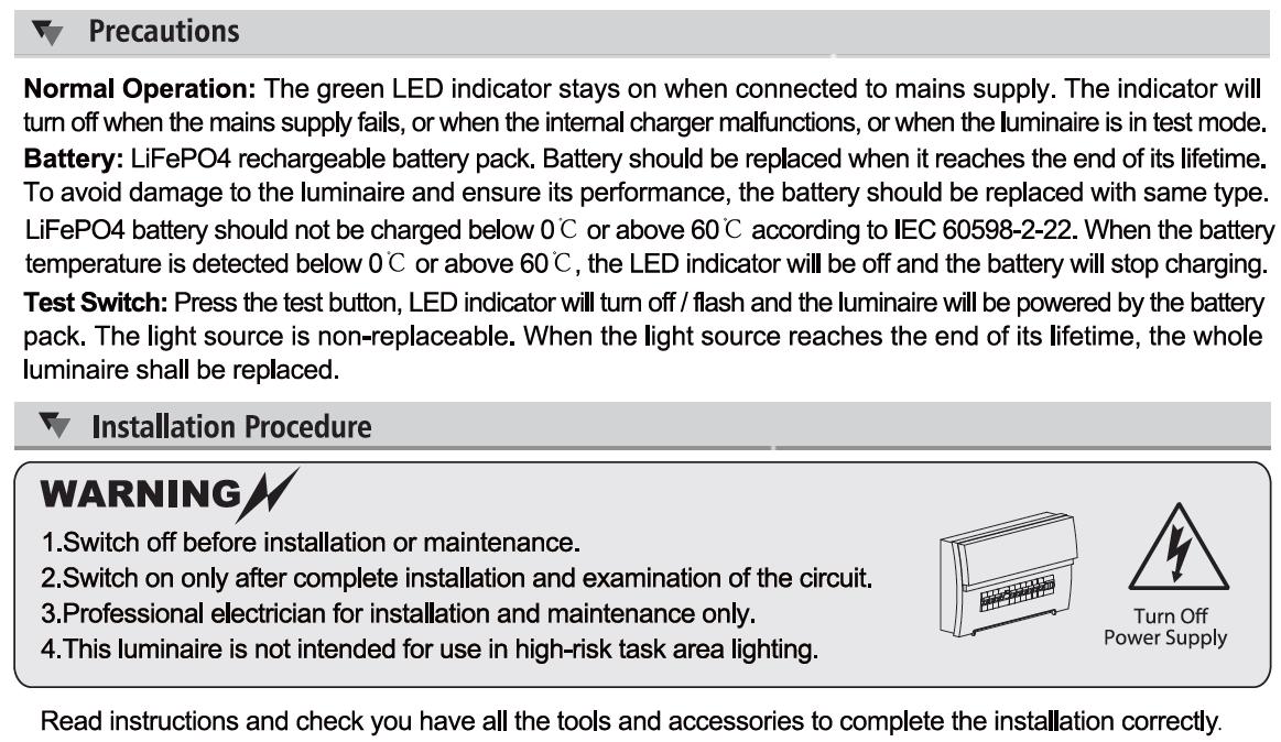
Safety
• Mains powered – installation must comply with building and electrical regulations.
• Always switch off and isolate the power before installation or maintenance.
Need Help?

For advice or accessories, contact us at the address above. Please have the product name, model, and purchase details ready STANDARD VERSION
LUMINAIRE INSTALLATION
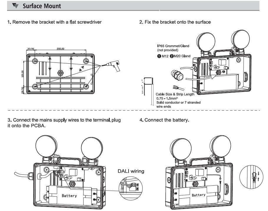
1. Unclip the front cover using a flat blade screwdriver, and carefully inserting it into & releasing the 6 clip points (2 each side, one top & bottom).
2. Secure the luminaire in position using the drill out points provided on the back wall of the luminaire body
3. Drill out the desired 20mm diameter cable entry point (located on each side wall of the luminaire body) & fit the cable gland provided
4. Route the power supply cable through the cable gland to the terminal block and terminate ensuring correct polarity is observed
5. Plug the Battery loom onto the PCB connector marked BATT.
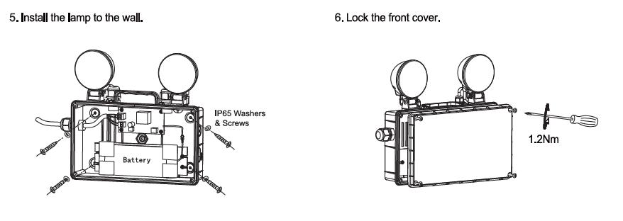
6. Rotate & angle the lamp heads to the required direction. The bolts/screws on the lamp heads may need to be loosened to do this –ensure they are re-tightened afterwards to hold position.
7. Refit the front cover to the luminaire body
8. Connect the power supply & check that the green indicator LED illuminates.
****************************** IMPORTANT WARNING ****************************
The luminaire uses Lithium Iron Phosphate cells (LiFeP04) in its battery pack. These batteries include overcharge protection circuitry and a Negative Temperature Co-efficient (NTC) third lead to control thermal runaway. When the battery is no longer able to provide its full rated duration, it must be replaced with an identical type. Please consult the manufacturer if in doubt.
MAINTENANCE
1. This luminaire MUST be disconnected before the circuit it is installed on is subjected to any high voltage or insulation resistance testing, otherwise irreparable damage will occur to luminaire components.
2. Ensure cleanliness of luminaires is maintained so as not to affect performance.
3. The battery in this luminaire must be replaced when it is no longer able to meet its rated duration.
4. The luminaire operating temperature range is 0⁰C - +40⁰C.


TESTING FOR EMERGENCY LUMINAIRES
Recommended routine test procedures in line with BS 5266 & BS EN 50172:
Monthly Functional Test
• Simulate a mains supply failure by isolating the circuit (ensuring if it is safe to do so) or by way of a test key switch if fitted into the circuit.
• Do this for a period of time (usually 30s) to check that the light source illuminates from the battery supply.
• Once complete, ensure the normal supply is restored & that the green LED charge indicator illuminates.
• Log result/comments in the emergency lighting logbook.
Annual Discharge Test
• Simulate a mains supply failure by isolating the circuit (ensuring if it is safe to do so) or by way of a test key switch if fitted into the circuit.
• This should be for the full 3-hour rated duration.
• Check that the light source illuminates & remains illuminated for the full rated duration period.
• Once complete, ensure the normal supply is restored & that the green LED charge indicator illuminates.
• Log result/comments in the emergency lighting logbook.
SELF TEST VERSION
LUMINAIRE INSTALLATION
9. Unclip the front cover using a flat blade screwdriver, and carefully inserting it into & releasing the 6 clip points (2 each side, one top & bottom).
10. Secure the luminaire in position using the drill out points provided on the back wall of the luminaire body.
11. Drill out the desired 20mm diameter cable entry point (located on each side wall of the luminaire body) & fit the cable gland provided.
12. Route the power supply cable through the cable gland to the terminal block and terminate ensuring correct polarity is observed
13. Plug the Battery loom onto the PCB connector marked BATT.
14. Rotate & angle the lamp heads to the required direction. The bolts/screws on the lamp heads may need to be loosened to do this – ensure they are re-tightened afterwards to hold position.
15. Refit the front cover to the luminaire body
16. Ensure that the lamp heads are positioned so as to provide the required lux levels in line with the emergency lighting design and EN 1838:2013, and in a way that minimizes glare in an emergency situation.
17. Connect the power supply & check that the green indicator LED illuminates. At this time the luminaire will undertake an initial short functional self-test (please see below under ‘Self-Test Function’).
******************************
The luminaire uses Lithium Iron Phosphate cells (LiFeP04) in its battery pack. These batteries include overcharge protection circuitry and a Negative Temperature Co-efficient (NTC) third lead to control thermal runaway. When the battery is no longer able to provide its full rated duration, it must be replaced with an identical type. Please consult the manufacturer if in doubt.
MAINTENANCE
5. DO NOT INSULATION TEST.
6. Ensure cleanliness of luminaires is maintained so as not to affect performance.
7. The battery in this luminaire must be replaced when it is no longer able to meet its rated duration.
8. The luminaire operating temperature range is 0⁰C - +40⁰C.
SELF TEST FUNCTION
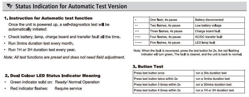
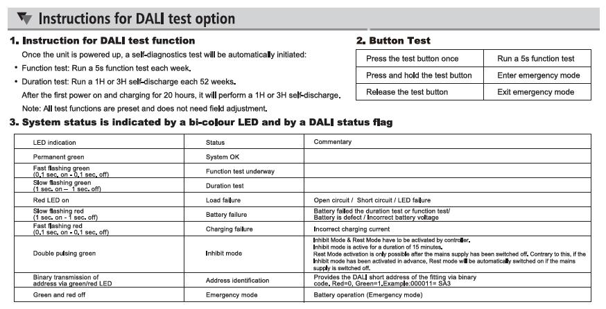
This luminaire comes with a built-in self-test facility. Once given a permanent mains supply, the luminaire will automatically carry out a monthly functional check & an annual full duration test, in line with the testing procedures of BS 5266 and BS EN 50172
Initial Test
• Upon receiving a permanent mains power supply, the luminaire will immediately carry out a short (30s) functional test. Following this it will charge for 24 hours before carrying out a 3-hour duration test. DO NOT REMOVE THE MAINS POWER SUPPLY DURING THIS PERIOD. During this test the lamp heads will illuminate & the LED status indicator will rapidly flash red.
Monthly Function Test
• The luminaire will carry out a 30 second function test, selected randomly between day 15 to day 30 after installation so that all self-test products do not go into test mode at the same time. During this test the lamp heads will illuminate & the LED status indicator will rapidly flash red This test will be repeated every 30 days.
Annual Duration Test
• After 11 monthly function tests, the luminaire will carry out a full rated duration test.
• The test will last 3 hours. During this time the lamp heads will illuminate & the LED status indicator will rapidly flash red.
FAULT INDICATORS
If during a self-test a fault is detected, it will be indicated as follows by the RED LED indicator:
• 1 flash every 3 seconds – Fault with battery. Maybe a battery failure & requires changing, or not connected properly.
• 2 flashes every 3 seconds – Fault with LED module.
• 3 flashes every 3 seconds – Duration time not being met so batteries will need to be replaced.
NOTES
1. After completion of the tests listed above the luminaire will repeat the process of 11 monthly function tests & 1 annual duration test.
2. If there is a power outage before any of the tests, the luminaire will delay the test appropriately to ensure a minimum 24-hour charge is received.
3. A fault indicator will continue until the fault is rectified
4. A reset of the mains supply will be required to clear the fault code once it has been rectified
MANUAL TESTING
As this is a self-test product this is NOT recommended.
BLACK STANDARD VERSION
LUMINAIRE INSTALLATION
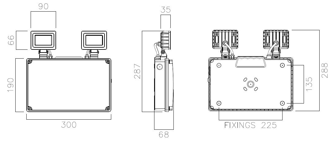
1. Unscrew 4 corner screws to remove the front cover from the main body.
2. Secure the luminaire in position using the drill out points provided on the back wall of the main body
3. Drill out the desired 20mm diameter cable entry point (located on each side wall of the luminaire body) & fit the cable gland provided
4. Route the power supply cable through the cable gland to the terminal block and terminate ensuring correct polarity is observed
5. Plug the Battery loom onto the PCB connector marked BATT.
6. Rotate & angle the lamp heads to the required direction. The bolts/screws on the lamp heads may need to be loosened to do this – ensure they are re-tightened afterwards to hold position.
7. Refit the front cover to the luminaire body
8. Connect the power supply and make sure the green charge indicator and lamp indicator LEDs illuminate. ******************************
IMPORTANT WARNING ****************************
The luminaire uses Lithium Iron Phosphate cells (LiFeP04) in its battery pack. These batteries include overcharge protection circuitry and a Negative Temperature Co-efficient (NTC) third lead to control thermal runaway.
When the battery is no longer able to provide its full rated duration, it must be replaced with an identical type. Please consult the manufacturer if in doubt.
MAINTENANCE:
9. This luminaire MUST be disconnected before the circuit it is installed on is subjected to any high voltage or insulation resistance testing, otherwise irreparable damage will occur to luminaire components.
10. Ensure cleanliness of luminaires is maintained so as not to affect performance.
11. The battery in this luminaire must be replaced when it is no longer able to meet its rated duration.
12. The luminaire operating temperature range is 0⁰C - +40⁰C.
TESTING FOR EMERGENCY LUMINAIRES:
Recommended routine test procedures in line with BS 5266 & BS EN 50172:
Monthly Functional Test:
• Simulate a mains supply failure by isolating the circuit (ensuring if it is safe to do so) or by way of a test key switch if fitted into the circuit.
• Do this for a period of time (usually 30s) to check that the light source illuminates from the battery supply.
• Once complete, ensure the normal supply is restored & that the green LED charge indicator illuminates.
• Log result/comments in the emergency lighting logbook.
Annual Discharge Test:
• Simulate a mains supply failure by isolating the circuit (ensuring if it is safe to do so) or by way of a test key switch if fitted into the circuit.
• This should be for the full 3-hour rated duration.
• Check that the light source illuminates & remains illuminated for the full rated duration period.
• Once complete, ensure the normal supply is restored & that the green LED charge indicator illuminates.
• Log result/comments in the emergency lighting logbook.