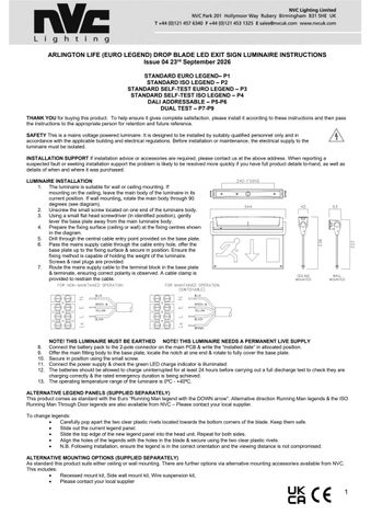
ARLINGTON LIFE (EURO LEGEND) DROP BLADE LED EXIT SIGN LUMINAIRE INSTRUCTIONS Issue 04 23rd September 2026 STANDARD EURO LEGEND– P1 STANDARD ISO LEGEND – P2 STANDARD SELF-TEST EURO LEGEND – P3 STANDARD SELF-TEST ISO LEGEND – P4 DALI ADDRESSABLE – P5-P6 DUAL TEST – P7-P9 THANK YOU for buying this product. To help ensure it gives complete satisfaction, please install it according to these instructions and then pass the instructions to the appropriate person for retention and future reference. SAFETY This is a mains voltage powered luminaire. It is designed to be installed by suitably qualified personnel only and in accordance with the applicable building and electrical regulations. Before installation or maintenance, the electrical supply to the luminaire must be isolated. INSTALLATION SUPPORT If installation advice or accessories are required, please contact us at the above address. When reporting a suspected fault or seeking installation support the problem is likely to be resolved more quickly if you have full product details to-hand, as well as details of when and where it was purchased. LUMINAIRE INSTALLATION 1. The luminaire is suitable for wall or ceiling mounting. If mounting on the ceiling, leave the main body of the luminaire in its current position. If wall mounting, rotate the main body through 90 degrees (see diagram). 2. Unscrew the small screw located on one end of the luminaire body. 3. Using a small flat head screwdriver (in identified position), gently lever the base plate away from the main luminaire body. 4. Prepare the fixing surface (ceiling or wall) at the fixing centres shown in the diagram. 5. Drill through the central cable entry point provided on the base plate. 6. Pass the mains supply cable through the cable entry hole, offer the base plate up to the fixing surface & secure in position. Ensure the fixing method is capable of holding the weight of the luminaire. Screws & rawl plugs are provided. 7. Route the mains supply cable to the terminal block in the base plate & terminate, ensuring correct polarity is observed. A cable clamp is provided to restrain the cable.
NOTE! THIS LUMINAIRE MUST BE EARTHED NOTE! THIS LUMINAIRE NEEDS A PERMANENT LIVE SUPPLY Connect the battery pack to the 2-pole connector on the main PCB & write the “installed date” in allocated position. Offer the main fitting body to the base plate, locate the notch at one end & rotate to fully cover the base plate. Secure in position using the small screw. Connect the power supply & check the green LED charge indicator is illuminated. The batteries should be allowed to charge uninterrupted for at least 24 hours before carrying out a full discharge test to check they are charging correctly & the rated emergency duration is being achieved. 13. The operating temperature range of the luminaire is 0⁰C - +40⁰C. 8. 9. 10. 11. 12.
ALTERNATIVE LEGEND PANELS (SUPPLIED SEPARATELY) This product comes as standard with the Euro “Running Man legend with the DOWN arrow”. Alternative direction Running Man legends & the ISO Running Man Through Door legends are also available from NVC – Please contact your local supplier. To change legends: • Carefully pop apart the two clear plastic rivets located towards the bottom corners of the blade. Keep them safe. • Slide out the current legend panel. • Slide the top edge of the new legend panel into the head unit. Repeat for both sides. • Align the holes of the legends with the holes in the blade & secure using the two clear plastic rivets. • N.B. Following installation, ensure the legend is in the correct orientation and the viewing distance is not compromised. ALTERNATIVE MOUNTING OPTIONS (SUPPLIED SEPARATELY) As standard this product suits either ceiling or wall mounting. There are further options via alternative mounting accessories available from NVC. This includes: • Recessed mount kit, Side wall mount kit, Wire suspension kit, • Please contact your local supplier
1
ARLINGTON LIFE (ISO LEGEND) LED EXIT SIGN LUMINAIRE INSTRUCTIONS LUMINAIRE INSTALLATION (CEILING OR WALL) 1. Decide if mounting on ceiling or wall. If: Ceiling then leave main body of fitting in current position Wall the rotate the main body 90 degree (see diagram) 2. Undo the small screw located on one end of the fitting body. 3. Use a small flat head screwdriver (in identified position) to lever the base plate away from the main fitting body. 4. Prepare the fixing surface (ceiling or wall) at the fixing centres shown in the diagram & provide a central mains supply cable. 5. Drill open the central cable entry point on the base plate. 6. Pass the mains supply cable through the cable entry hole in the fixing base plate, offer the base plate up to the fixing surface & secure. Ensure the fixing method is capable of holding the weight of the luminaire. Screws & rawl plugs are provided. 7. Route the mains supply cable to the terminal block in the base plate & terminate, ensuring correct polarity is observed. A cable clamp is provided to restrain the cable.
NOTE! THIS LUMINAIRE MUST BE EARTHED NOTE! THIS LUMINAIRE NEEDS A PERMANENT LIVE SUPPLY Connect the battery pack to the 2-pole connector on the main PCB & write the “installed date” in allocated position. Offer the main fitting body to the base plate, locate the notch at one end & rotate to fully cover the base plate. Secure in position using the small screw. Reconnect the power supply & check the green LED charge indicator is illuminated. The batteries should be allowed to charge for at least 24 hours before carrying out a full discharge test to check they are charging correctly & the maintained duration is being achieved. 13. The operating temperature range of the luminaire is 0⁰C - +40⁰C. 8. 9. 10. 11. 12.
ALTERNATIVE LEGEND PANELS (SUPPLIED SEPARATELY) This product comes as standard with an ISO “Running Man Through Door” legend fitted. Alternative legends are also available from NVC – Please contact your local supplier. To change legends: • Carefully pop apart the two clear plastic rivets located towards the bottom corners of the blade. Keep them safe. • Slide out the current legend panel. • Slide the top edge of the new legend panel into the head unit. Repeat for both sides. • Align the holes of the legends with the holes in the blade & secure using the two clear plastic rivets. • N.B. Following installation, ensure the legend is in the correct orientation and the viewing distance is not compromised. ALTERNATIVE MOUNTING OPTIONS (SUPPLIED SEPARATELY) As standard this product suits either ceiling or wall mounting. There are further options via alternative mounting accessories available from NVC. This includes: • Recessed mount kit • Side wall mount kit • Wire suspension kit • Please contact your local supplier ****************************** IMPORTANT WARNING **************************** The luminaire uses Lithium Iron Phosphate cells (LiFeP04) in its battery pack. These batteries include overcharge protection circuitry and a Negative Temperature Co-efficient (NTC) third lead to control thermal runaway. When the battery is no longer able to provide its full rated duration, it must be replaced with an identical type. Please consult the manufacturer if in doubt. OPERATION / MAINTENANCE • Nominal battery life is designed to be at least 4 years. They should be replaced when they no longer achieve the 3 hour full duration. • This luminaire MUST be disconnected before the circuit it is installed on is subjected to any high voltage or insulation resistance testing, otherwise irreparable damage will occur to luminaire components. • Ensure cleanliness of luminaires is maintained so as not to affect performance.
2
ARLINGTON LIFE (EURO LEGEND) DROP BLADE LED SELF-TEST EXIT SIGN LUMINAIRE INSTRUCTIONS LUMINAIRE INSTALLATION 1. The luminaire is suitable for wall or ceiling mounting. If mounting on the ceiling, leave the main body of the luminaire in its current position. If wall mounting, rotate the main body through 90 degrees (see diagram). 2. Undo the small screw located on one end of the luminaire body. 3. Use a small flat head screwdriver (in identified position), gently lever the base plate away from the main luminaire body. 4. Prepare the fixing surface (ceiling or wall) at the fixing centres shown in the diagram. 5. Drill through the central cable entry point provided on the base plate. 6. Pass the mains supply cable through the cable entry hole, offer the base plate up to the fixing surface & secure in position. Ensure the fixing method is capable of holding the weight of the luminaire. Screws & rawl plugs are provided. 7. Route the mains supply cable to the terminal block in the base plate & terminate, ensuring correct polarity is observed. A cable clamp is provided to restrain the cable.
8. 9. 10. 11. 12.
NOTE! THIS LUMINAIRE MUST BE EARTHED NOTE! THIS LUMINAIRE NEEDS A PERMANENT LIVE SUPPLY Connect the battery pack to the 2-pole connector on the main PCB & write the “installed date” in allocated position. Offer the main fitting body to the base plate, locate the notch at one end & rotate to fully cover the base plate. Secure in position using the small screw. Connect the power supply & check the green LED charge indicator is illuminated. The luminaire operating temperature range is 0⁰C - +40⁰C.
ALTERNATIVE LEGEND PANELS (SUPPLIED SEPARATELY) This product comes as standard with the Euro “Running Man legend with the DOWN arrow”. Alternative direction Running Man legends & the ISO Running Man Through Door legends are also available from NVC – Please contact your local supplier. To change legends: • Carefully pop apart the two clear plastic rivets located towards the bottom corners of the blade. Keep them safe. • Slide out the current legend panel. • Slide the top edge of the new legend panel into the head unit. Repeat for both sides. • Align the holes of the legends with the holes in the blade & secure using the two clear plastic rivets. • N.B. Following installation, ensure the legend is in the correct orientation and the viewing distance is not compromised. ****************************** IMPORTANT WARNING **************************** The luminaire uses Lithium Iron Phosphate cells (LiFeP04) in its battery pack. These batteries include overcharge protection circuitry and a Negative Temperature Co-efficient (NTC) third lead to control thermal runaway. When the battery is no longer able to provide its full rated duration, it must be replaced with an identical type. Please consult the manufacturer if in doubt. OPERATION / MAINTENANCE • Nominal battery life is designed to be at least 4 years. They should be replaced when they no longer achieve the 3 hour full duration. • This luminaire MUST be disconnected before the circuit it is installed on is subjected to any high voltage or insulation resistance testing, otherwise irreparable damage will occur to luminaire components. • Ensure cleanliness of luminaires is maintained so as not to affect performance.
3
ARLINGTON LIFE (ISO LEGEND) DROP BLADE LED SELF-TEST EXIT SIGN LUMINAIRE INSTRUCTIONS LUMINAIRE INSTALLATION (CEILING OR WALL) 1. Decide if mounting on ceiling or wall. If: Ceiling then leave main body of fitting in current position Wall the rotate the main body 90 degree (see diagram) 2. Undo the small screw located on one end of the fitting body. 3. Use a small flat head screwdriver (in identified position) to lever the base plate away from the main fitting body. 4. Prepare the fixing surface (ceiling or wall) at the fixing centres shown in the diagram & provide a central mains supply cable. 5. Drill open the central cable entry point on the base plate. 6. Pass the mains supply cable through the cable entry hole in the fixing base plate, offer the base plate up to the fixing surface & secure. Ensure the fixing method is capable of holding the weight of the luminaire. Screws & rawl plugs are provided. 7. Route the mains supply cable to the terminal block in the base plate & terminate, ensuring correct polarity is observed. A cable clamp is provided to restrain the cable.
8. 9. 10. 11.
NOTE! THIS LUMINAIRE MUST BE EARTHED NOTE! THIS LUMINAIRE NEEDS A PERMANENT LIVE SUPPLY Connect the battery pack to the 2-pole connector on the main PCB & write the “installed date” in allocated position. Offer the main fitting body to the base plate, locate the notch at one end & rotate to fully cover the base plate. Secure in position using the small screw. Reconnect the power supply & check the green LED charge indicator is illuminated.
ALTERNATIVE LEGEND PANELS (SUPPLIED SEPARATELY) This product comes as standard with the ISO “Running Man through door” legend. Alternative direction ISO legends & Euro legends are also available from NVC – Please contact your local supplier. To change legends: • Carefully pop apart the two clear plastic rivets located towards the bottom corners of the blade. Keep them safe. • Slide out the current legend panel. • Slide the top edge of the new legend panel into the head unit. Repeat for both sides. • Align the holes of the legends with the holes in the blade & secure using the two clear plastic rivets. • N.B. Following installation, ensure the legend is in the correct orientation and the viewing distance is not compromised. ****************************** IMPORTANT WARNING **************************** The luminaire uses Lithium Iron Phosphate cells (LiFeP04) in its battery pack. These batteries include overcharge protection circuitry and a Negative Temperature Co-efficient (NTC) third lead to control thermal runaway. When the battery is no longer able to provide its full rated duration, it must be replaced with an identical type. Please consult the manufacturer if in doubt. OPERATION / MAINTENANCE • Nominal battery life is designed to be at least 4 years. They should be replaced when they no longer achieve the 3 hour full duration. • This luminaire MUST be disconnected before the circuit it is installed on is subjected to any high voltage or insulation resistance testing, otherwise irreparable damage will occur to luminaire components. • Ensure cleanliness of luminaires is maintained so as not to affect performance.
4
ARLINGTON LIFE DAM3 DROP BLADE LED EXIT SIGN LUMINAIRE INSTRUCTIONS THANK YOU for buying this product. To help ensure it gives complete satisfaction, please install it according to these instructions and then pass the instructions to the appropriate person for retention and future reference. SAFETY This is a mains voltage powered luminaire. It is designed to be installed by suitably qualified personnel only and in accordance with the applicable building and electrical regulations. Before installation or maintenance, the electrical supply to the luminaire must be isolated. INSTALLATION SUPPORT If installation advice or accessories are required, please contact us at the above address. When reporting a suspected fault or seeking installation support the problem is likely to be resolved more quickly if you have full product details to-hand, as well as details of when and where it was purchased. LUMINAIRE INSTALLATION 1. The luminaire is suitable for wall or ceiling mounting. If mounting on the ceiling, leave the main body of the luminaire in its current position. If wall mounting, rotate the main body through 90 degrees (see diagram). 2. Unscrew the small screw located on one end of the luminaire body. 3. Using a small flat head screwdriver (in identified position), gently lever the base plate away from the main luminaire body. 4. Prepare the fixing surface (ceiling or wall) at the fixing centres shown in the diagram. 5. Drill through the central cable entry point provided on the base plate. 6. Pass the mains supply cable through the cable entry hole, offer the base plate up to the fixing surface & secure in position. Ensure the fixing method is capable of holding the weight of the luminaire. Screws & rawl plugs are provided. 7. Route the mains supply cable to the terminal block in the base plate & terminate, ensuring correct polarity is observed. A cable clamp is provided to restrain the cable.
8. 9. 10. 11. 12.
Connect the battery pack to the 2-pole connector on the main PCB & write the “installed date” in allocated position. Offer the main fitting body to the base plate, locate the notch at one end & rotate to fully cover the base plate. Secure in position using the small screw. Connect the power supply & check the green LED charge indicator illuminates. The batteries should be allowed to charge uninterrupted for at least 24 hours before carrying out a full discharge test to check they are charging correctly & the rated emergency duration is being achieved. 13. The operating temperature range of the luminaire is 0⁰C - +40⁰C. ALTERNATIVE LEGEND PANELS (SUPPLIED SEPARATELY) This product comes as standard with the Euro “Running Man legend with the DOWN arrow”. Alternative direction Running Man legends & the ISO Running Man Through Door legends are also available from NVC – Please contact your local supplier. To change legends: • Carefully pop apart the two clear plastic rivets located towards the bottom corners of the blade. Keep them safe. • Slide out the current legend panel. • Slide the top edge of the new legend panel into the head unit. Repeat for both sides. • Align the holes of the legends with the holes in the blade & secure using the two clear plastic rivets. N.B. Following installation, ensure the legend is in the correct orientation and the viewing distance is not compromised. ****************************** IMPORTANT WARNING **************************** The luminaire uses Lithium Iron Phosphate cells (LiFeP04) in its battery pack. These batteries include overcharge protection circuitry and a Negative Temperature Co-efficient (NTC) third lead to control thermal runaway. When the battery is no longer able to provide its full rated duration, it must be replaced with an identical type. Please consult the manufacturer if in doubt. OPERATION / MAINTENANCE • If the battery is replaced, it is imperative that the exact type, including voltage, capacity and chemistry as the original manufacturer’s battery is used. Please consult the manufacturer when replacing the battery. • Please ensure where applicable that the self-adhesive escape route legend (included) is oriented correctly, fixed securely, and that the viewing distance in line with BS 5499-4:2013 and BS EN 1838:2013 is not compromised. • Ensure cleanliness of luminaires is maintained so as not to affect the performance and/or compromise the light level.
5
DALI/AutoTest variants automatically test their function and performance in accordance with BS EN 62034 and BS EN 50172:2004. A 30 second function test is performed automatically at 30-day intervals. This test can be initiated manually at any time by switching the live supply Off/On twice within 5 seconds. Full duration tests are performed automatically once a year and can be manually initiated subsequent to an uninterrupted charge period of not less than 24 hours. Note: The control gear in this product defaults to its automatic self-test facility in the absence of a DALI subnet supply. As a consequence, tests may occur at any time and caution should be taken where this may be inconvenient, such as in hospitals, hospitals, and other premises with sleeping accommodation. The addition of the DALI subnet alleviates this as tests can be scheduled to occur at periods of low risk and least disturbance. Commissioning: On initial power up, DALI and AutoTest variants will begin an automatic commissioning process as outlined in the table below. The permanent live supply should not be interrupted during this process. During the process emergency operation will be inhibited. LED Indication Green 0.5Hz flash Green 0.5Hz flash Green 0.5Hz flash Green with 10 second pulse
Stage / Period 1 - 24h 2 – Rated Duration 3 – 24h 4 – Normal Operation
Status Initial Battery Charge Duration Test Battery Recharge Commissioning Complete
LED Status Indicator: LED Indication Green with 10 second pulse Green 0.5Hz flash Green 2Hz flash Green double pulse, 10 seconds off Red 0.5Hz flash Red 2Hz flash Off
Status Normal, Commissioned, Standby Mode Commissioning or Duration Test in Progress Function Test in Progress Rest Mode or Flat Battery Charging or Battery Fault Lamp Fault No Power and Battery Disconnected / Flat
DALI Communications: DALI variants allow two-wire communication between the units ‘DA’ terminals and a central monitoring & control system designed to meet the standards of BS EN 62386, supporting parts 101, 102, and 202.
6
ARLINGTON LIFE DROP BLADE LED EXIT SIGN DUAL TEST INSTRUCTIONS Thank you for your purchase For best results, have this light fitting installed by a qualified electrician, following these instructions. Keep this leaflet for future reference. Safety
• •
Mains powered – installation must comply with building and electrical regulations. Always switch off and isolate the power before installation or maintenance.
Need Help? For advice or accessories, contact us at the address above. Please have the product name, model, and purchase details ready.
CEILING MOUNTED INSTALLATION
1. 2. 3. 4.
Feed mains cables through the ceiling. Unscrew and open the top housing cover. Drill the entry hole. Secure the top panel to the mounting surface. Connect the mains cable to the terminal, ensuring correct polarity and isolated power supply.
7
MAINTAINED OPERATION (NON-SWITCHABLE) Blue
5. 6. 7.
MAINTAINED OPERATION (SWITCHABLE) Blue
NON-MAINTAINED OPERATION Blue
Connect the battery cable. Install the product into the suspended bracket. Connect the power supply & check the green LED charge indicator illuminates.
FRONT MOUNTED INSTALLATION
1. 2. 3. 4. 5. 6. 7.
Feed mains cable through the wall. Unscrew and open the top housing cover. Drill the entry hole. Secure the top panel to the mounting surface Connect the mains cable to the terminal, ensuring correct polarity and isolated power supply. See wiring diagrams above. Connect the battery cable. Rotate the product and install it onto the top cover Connect the power supply & check the green LED charge indicator illuminates.
ALTERNATIVE LEGEND PANELS (SUPPLIED SEPARATELY) This product comes as standard with the Euro “Running Man legend with the DOWN arrow”. Alternative direction Running Man legends & the ISO Running Man Through Door legends are also available from NVC – Please contact your local supplier. To change legends: • Carefully pop apart the two clear plastic rivets located towards the bottom corners of the blade. Keep them safe. • Slide out the current legend panel. • Slide the top edge of the new legend panel into the head unit. Repeat for both sides. • Align the holes of the legends with the holes in the blade & secure using the two clear plastic rivets. • N.B. Following installation, ensure the legend is in the correct orientation and the viewing distance is not compromised. ALTERNATIVE MOUNTING OPTIONS (SUPPLIED SEPARATELY) As standard this product suits either ceiling or wall mounting. There are further options via alternative mounting accessories available from NVC. This includes: • Recessed mount kit • Side wall mount kit • Wire suspension kit • Please contact your local supplier
8
SELECTABLE MANUAL-TEST AND SELF-TEST MODES The product is set to manual test mode as default. The green jumper cap to change this can be located on the PCB. Note: Removing or repositioning the jumper cap while the product is powered will not change the operating mode. To change the operating mode: 1. Disconnect the 230V AC mains supply. 2. Disconnect the battery. 3. Move the jumper cap to the required mode position. 4. Reconnect the battery. 5. Reconnect the 230V AC mains supply. The product will then start in the selected mode and operate according to the relevant test procedure. Important: Always disconnect both the 230V AC mains supply and the battery before changing the jumper cap position
*For self-test operation, apply the classification code label supplied over the existing code on the fitting label.* OPERATION / MAINTENANCE • This luminaire includes a Lithium Iron Phosphate (LiFePO₄) battery pack which incorporates a battery management system to prevent overcharge, deep-discharge, and thermal runaway. When it is no longer able to provide it’s full, rated duration, it must be replaced with an identical type, including chemistry, voltage and capacity. IF IN DOUBT, PLEASE CONSULT THE LUMINAIRE MANUFACTURER. • Ensure cleanliness of luminaires is maintained so as not to affect performance. TESTING FOR EMERGENCY LUMINAIRES Recommended routine test procedures in line with BS 5266 & BS EN 50172: AUTOMATIC SEQUENCE FOR PRODUCTS SET TO SELF TEST 1. 2. 3. 4. 5. 6. 7. 8.
Once the product is installed and powered, it will automatically begin its commissioning cycle: Initial charge: The product charges for 24 hours. Initial duration test: A full 3-hour discharge test is then performed. Recharge: The product charges for a further 24 hours. First function test: Within 15–30 days, the product performs a 10-minute function test. Regular function tests: A 10-minute function test is then performed every 30 days. Annual duration test: After approximately 12 months, the product performs a full 3-hour discharge test. The 30-day function test cycle then resumes.
*Important: Power must not be interrupted during the initial commissioning cycle* Under normal operation, the product performs 11 × 10-minute function tests and 1 × 3-hour discharge test each year. PACKAGING RECYCLING Separate packaging materials before disposal. Recycle cardboard with paper and cardboard waste and PE bags with plastic packaging waste, where locally accepted. Follow local recycling requirements.
9