
Head

Safety
Always follow the instructions that accompany a Warning or Caution. These notices are provided to help prevent injury, death, and equipment damage during installation or maintenance.
• WARNING – Indicates a potentially hazardous situation that, if not avoided, could result in serious injury or death.
• CAUTION – Indicates a potentially hazardous situation that, if not avoided, may result in minor or moderate injury.
• NOTE – The absence of a warning doesn't mean the task is risk-free. Always stay alert and follow safe work practices.
Warnings
• WARNING – Feeder house/Header Drop Hazard
The feeder house or other hydraulically supported components can drop unexpectedly if hydraulic pressure is lost. Always lower the feeder house completely to the ground or install mechanical locks or rated support stands before working underneath.
• WARNING – Unexpected Machine Start-Up
If the combine is started while you are working on it, serious or fatal injuries may occur. Always remove the ignition key and disconnect the battery before working.
• WARNING – Electrical Fire or System Damage Risk
Improper wiring can result in short circuits, overheating, or fire especially in agricultural environments with dust and debris. Use only approved components and follow the installation wiring diagrams and specifications provided with this system. Do not modify the harnesses or connectors unless instructed.
• WARNING – Unstable Working Conditions
Always park the machine on firm, level ground before performing any installation or maintenance. Uneven or sloped surfaces increase the risk of unexpected movement, tipping, or falling components, which may lead to equipment damage or personal injury. Engage the parking brake and chock wheels if necessary.
Cautions
• CAUTION – Routing of Cables
Ensure electrical wiring is routed away from heat sources, sharp edges, and moving parts. Improper routing can lead to abrasion or short circuits.
• CAUTION – Electrical Short Hazard
While working on the machine’s electrical system, disconnect the battery to avoid short circuits and damaging electrical components.
• CAUTION – Battery Safety
Battery terminals may contain lead. Wash hands after contact. Prevent accidental short circuits by keeping tools and terminals clear of conductive materials.
• CAUTION – Do Not Pressure Wash Sensitive Components
Avoid spraying high-pressure water or air at electrical connectors, hydraulic seals, control units, or sensors. Moisture or debris can cause malfunctions or corrosion.
What’s in the Box
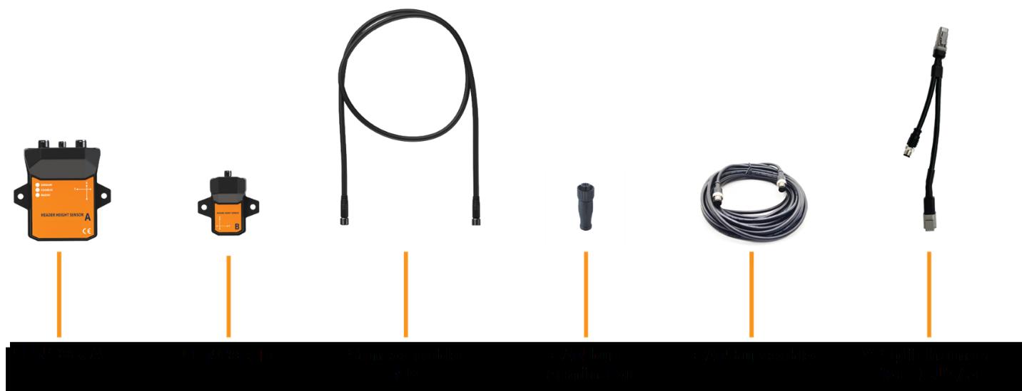
- Sensor A – master sensor body
- Sensor B – remote sensor body
- Sensor wire
- CANbus M12 wire
- CANbus M12 terminator
- Y-split (only for retrofit version)
- Alcohol swabs (not pictured)
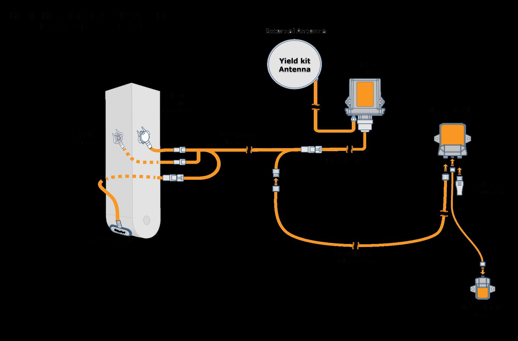
kit 2 or 3 Retrofit Installation
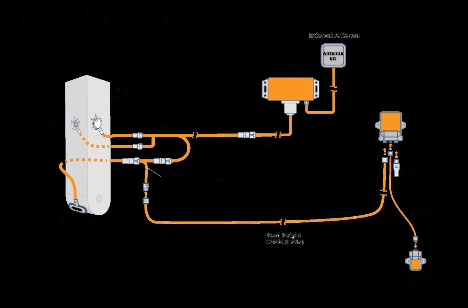
How it Works
Each sensor contains an inertial measurement unit (IMU) which can determine its orientation relative to the ground.
Sensor A is mounted to a fixed point on the combine frame, Sensor B to the feeder house. Once calibrated, the relative angle between Sensor B and Sensor A are used to determine the height of the header. By using the relative angle it can still function even when the combine is going up, down, or on sidehills.
Yield
Installation
When choosing an installation location, ensure you have enough free wire to accommodate completely lowering the feeder house. Sensor B typically will mount close to the hinge point of the feeder house to reduce amount of distance it will travel when the feeder house lowers.
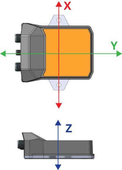
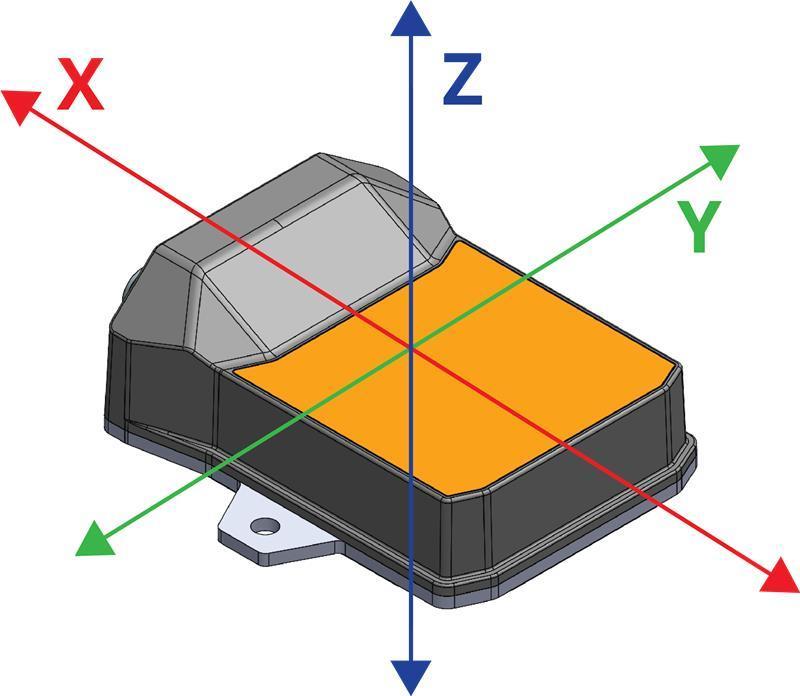
Both Sensor A and Sensor B can be mounted in any orientation, as long as one axis is parallel to the wheel axle
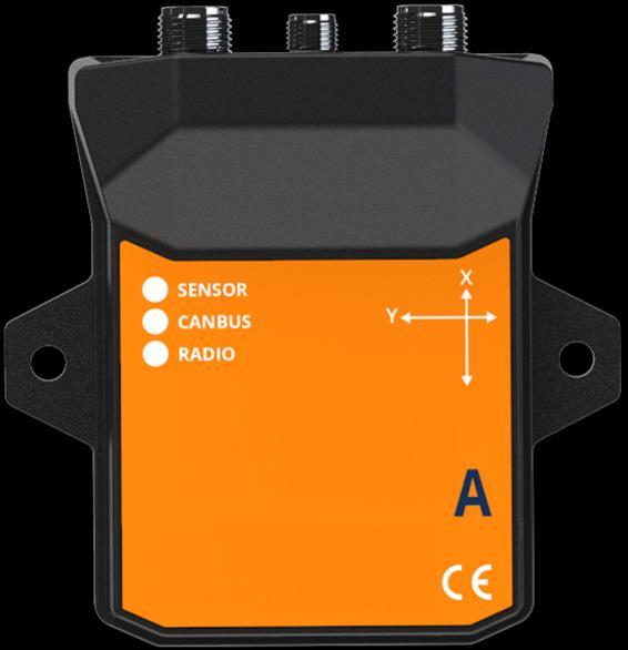
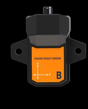
Note: On each label, the X and Y directions are clearly marked. The Z-Direction is pointing upwards
Determine Mount Location
Connect Sensor A to Sensor B using the M8 sensor wire. The wire is directional, connect the 6-pin end to the Sensor A and 4-pin end to Sensor B.
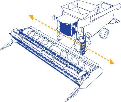
The Header Height Sensor must be mounted so that one of its axes is parallel with the axis running through the front axle of the combine (yellow line in image opposite). It does not matter which axis is parallel to the combine’s axle, either X, Y or Z will work.
1. Determine mounting location for Sensor A (parent sensor). Underneath the cab, there are many possible mounting locations that will allow the sensors X, Y or Z axis to run parallel to the combine’s front axle. The following images are some photographs of example installations:
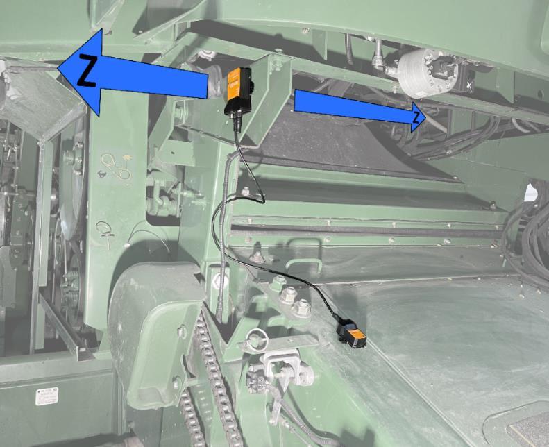
Z-Axis is parallel with the wheel axles – Connectors facing down
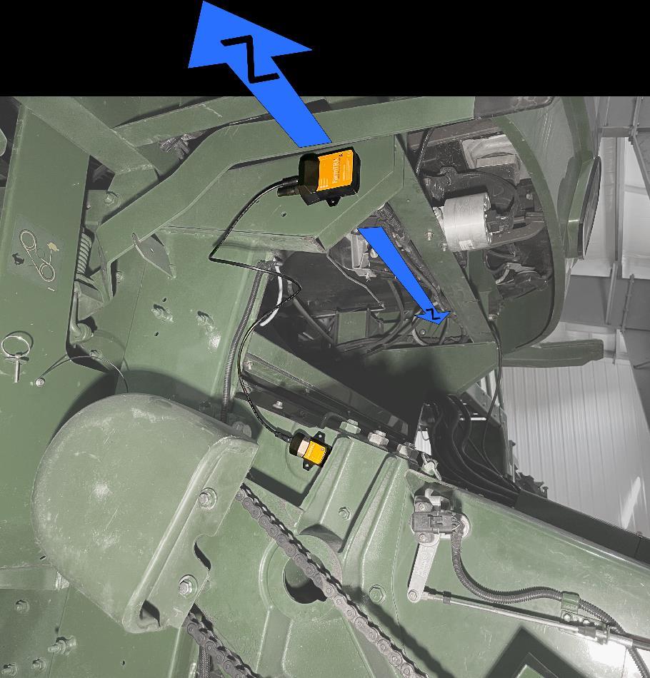
Z-Axis is parallel with the wheel axles – Connectors facing back of combine
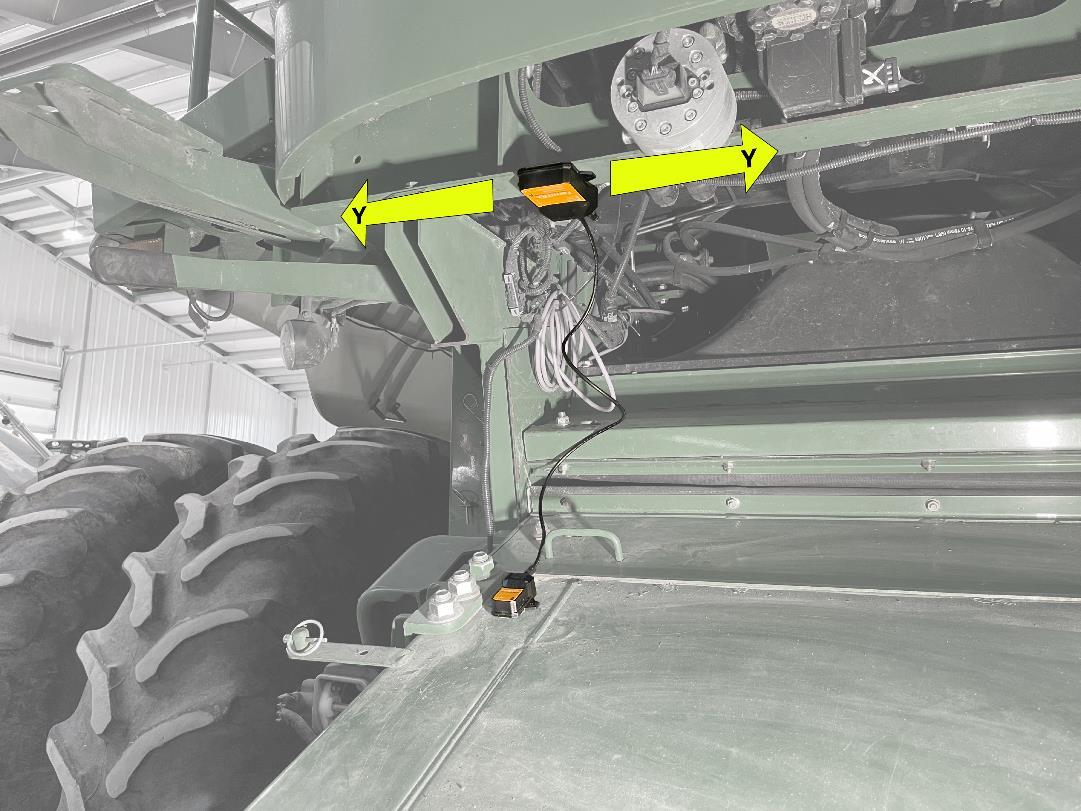
Y-Axis is parallel with the wheel axles – Connectors facing back of combine.
The same principles of mounting apply to Sensor B. It is usually simplest to mount the sensor with the label facing up and connectors backwards, like shown in the images above.
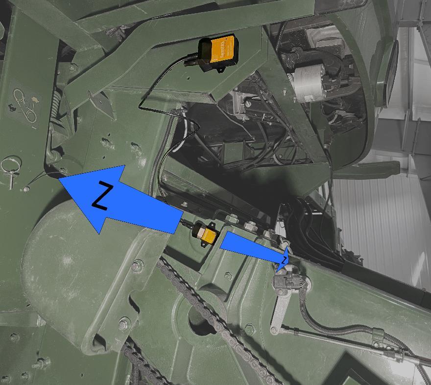
Z-Axis is parallel with the wheel axles – Connectors facing back of combine.
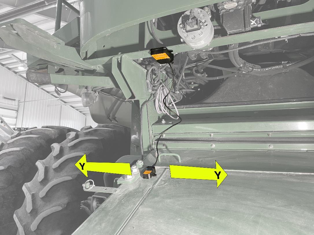
Y-Axis is parallel with the wheel axles – Connectors facing back of combine. Once the ideal mounting location has been determined for your combine, proceed to the next step.
Connecting to Wire Harness
If you are attaching a head height sensor to a Yield kit ECU 2.0 or ECU 3.0 (generation 2 or 3), skip to section below for “Retrofit Install”. The Yield Monitor Pro comes with an M12 connector branching off the head of the interconnect harness. There will be a CANbus terminator threaded on to this connector.
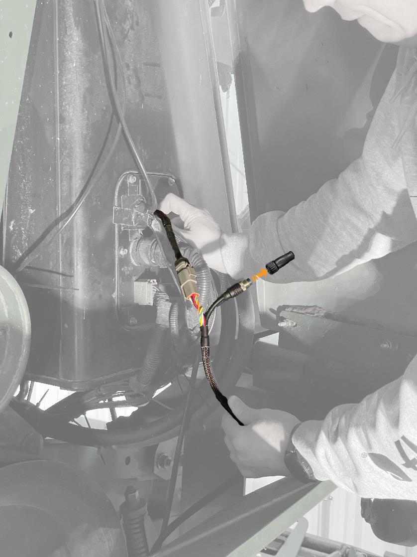
1. Remove the CAN terminator by unthreading and set aside somewhere safe.
2. Attach the M12 CAN wire, it is bi-directional and be installed either way.
3. Route the CAN wire under the cab towards Head Height Sensor A. Use zip ties to secure it to existing wires running underneath the cab. Make sure the wire is tightly secured and will not interfere with mechanical linkages.
4. Thread the CAN wire on to Head Height Sensor A.
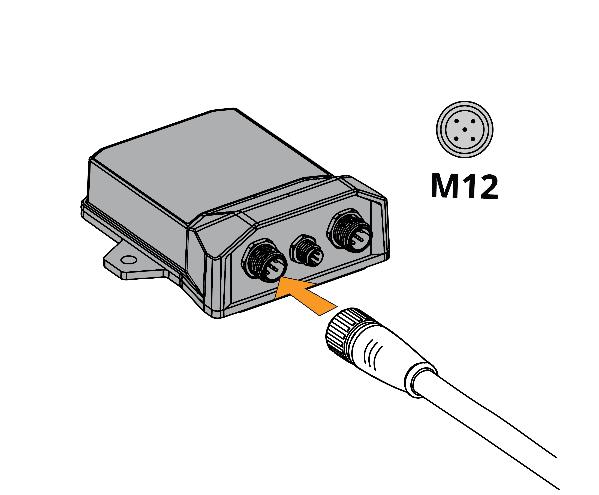
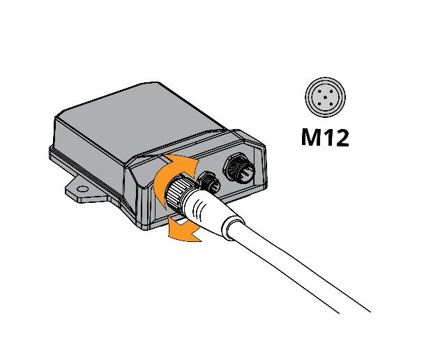
5. Thread the CAN terminator set aside in step 1 on to the second M12 connector on Head Height Sensor A.
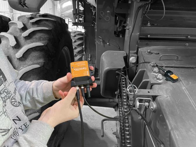
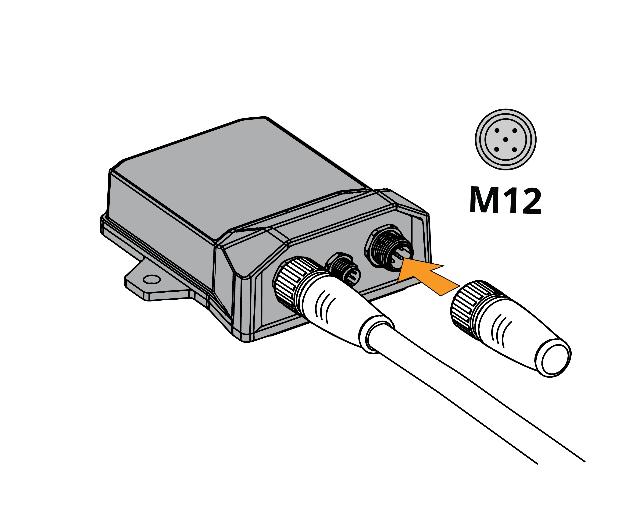
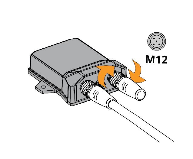
Sensor A connected with CAN wire and CAN terminator.
Retrofit to Yield kit ECU 2.0 or ECU 3.0 systems
For Yield kit ECU 2.0, or ECU 3.0 (generation 2, 3, respectively), the head height sensor must be installed at the end of the CANbus to conform to CANbus electrical requirements.
1. Disconnect the moisture sensor from the end of the interconnect harness
2. Connect the provided Y-split adapter to end of interconnect harness
3. Re-connect the moisture sensor to Y-splitter
4. Attach the M12 CAN wire, it is bi-directional and be installed either way.
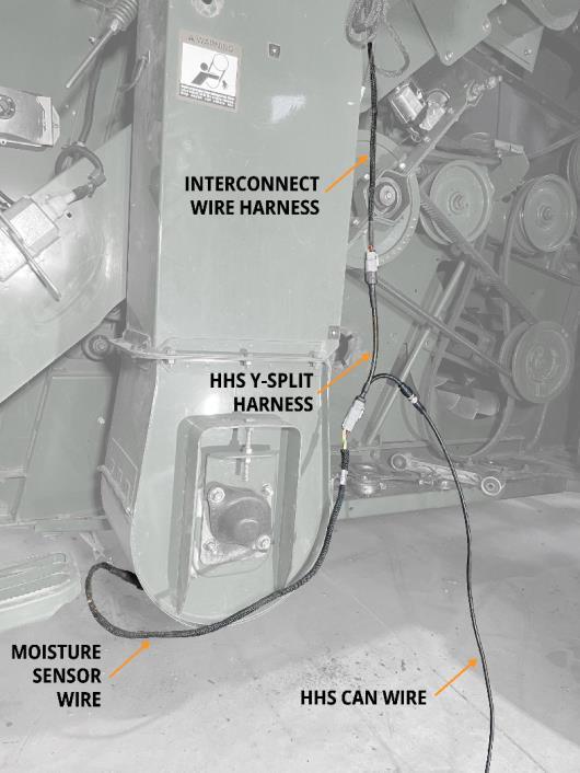
Wire placement for retrofit connection.
5. Route the CAN wire to the Head Height Sensor A under the cab. The best solution will be to re-trace the path of the yield monitor wire harness and zip tie the CAN wire to the existing harness. Make sure the wire is tightly secured and will not interfere with mechanical linkages.
6. Thread the CAN wire on to Head Height Sensor A.
7. Thread the provided CAN terminator on to the second M12 connector on Head Height Sensor A.
8. Carefully secure excess wire.
Mounting Sensors
1. Connect Sensor A to Sensor B using the M8 sensor wire.
a. The M8 sensor wire is directional, (Sensor A accepts 6-pin, sensor B accepts 4pin) ensure the labels on the wire are connected to the right sensor body.
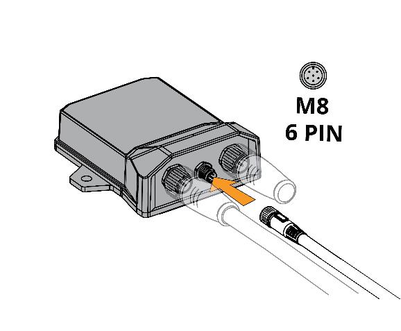
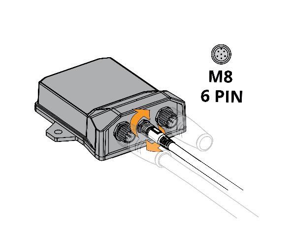
A - 6-pin connection
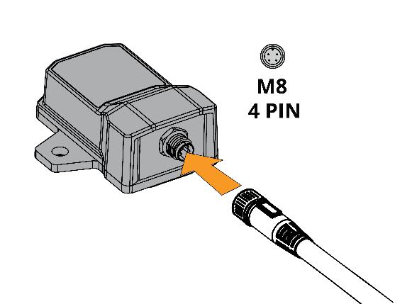
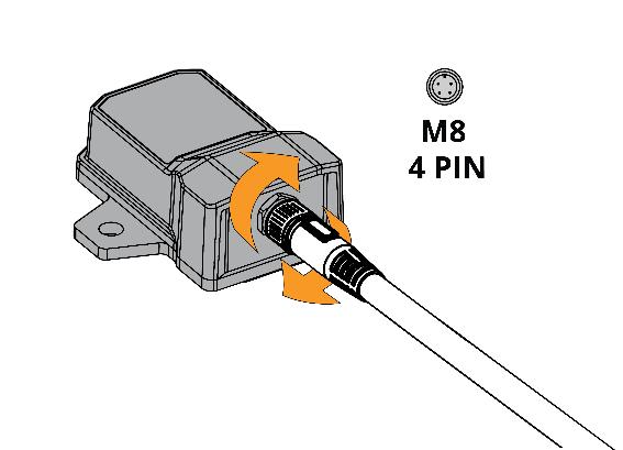
B - 4-pin connection
2. Hard Fastening (OPTIONAL)
This is optional, using the provided VHB will keep the sensors secured if properly applied. However, if preferred, and depending on mounting location, the sensors can be hard fastened using steps below. Skip to step 3 if only using VHB.
a. Use the provided drilling templates
b. use a centre punch and drill into your combine with a drill bit sized for metric M5 or #10 imperial fasteners
Sensor
Sensor
3. Prepare surface for VHB mount.
a. Wipe away dust and build-up.
b. Once clean of dust, wipe down surface with provided isopropyl alcohol swabs
c. Allow alcohol to evaporate
4. Once dry, remove red VHB backing and firmly press on the sensor
a. Bond strength is improved by good pressure and ideally applied at 21°C (70°F) or greater. Minimum temperature for application is 10°C (50°F).
5. If hard fastening, use self-tapping screws or standard screws + washers and lock nuts (not provided) to secure sensors.
Note: be aware of the fastener clearance on the opposing side of the mounting face.
In App Setup
Now that installation is complete, there are two steps left to calibrate the sensors for your combine. The first step is to orient the sensor bodies. The second step is to set the height range for the installed header and establish a maximum cutting height. Once a maximum cutting height is set, the yield monitor will not count area if the header is lifted above the set threshold.
Installation Calibration
Ensure that the combine is on level ground. Power up the system and connect to the Yield Monitor listed in the available devices section of the Harvest Mobile App. After connection is established, you will need to orient the device based off the direction the labels and connectors are facing.
1. Navigate to the app Main Menu by pressing the icon
2. Select “Device Calibration”

3. Under Header Height Sensor, select “Install Calibration”
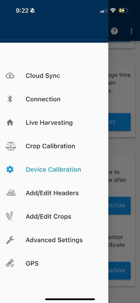
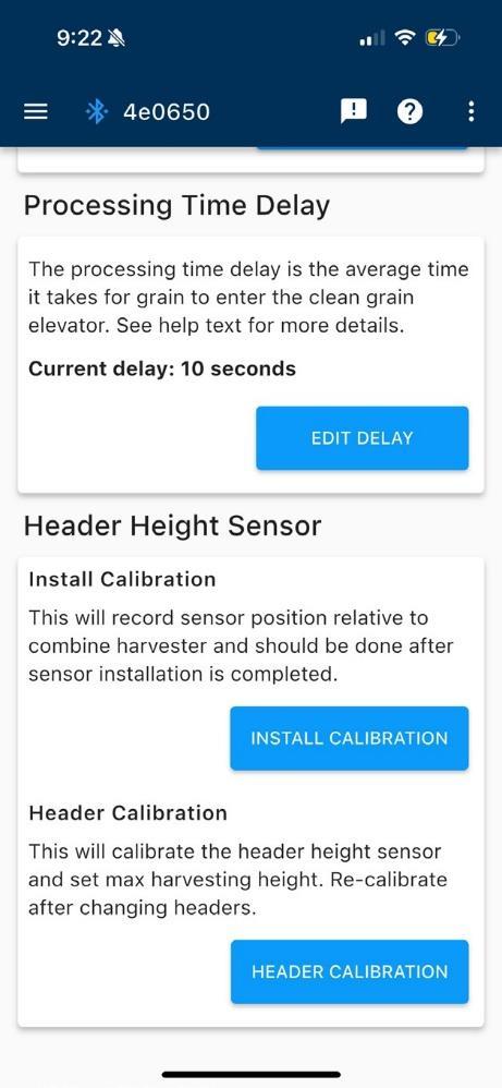
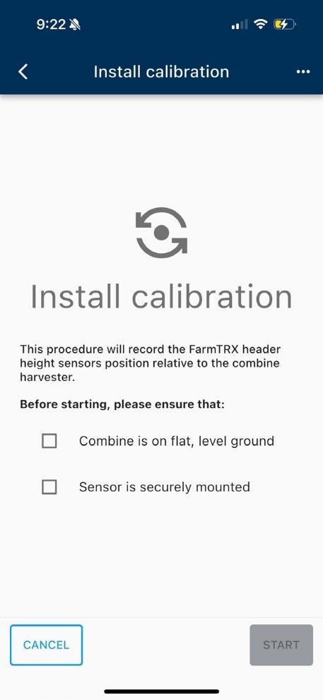
4. Confirm the combine is on flat, level ground and the sensor is securely mounted, then press “Start”
5. Using the direction the combine is facing as “forward,” follow the prompts to orient the sensors:
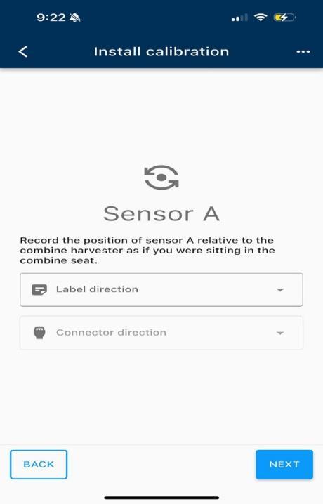
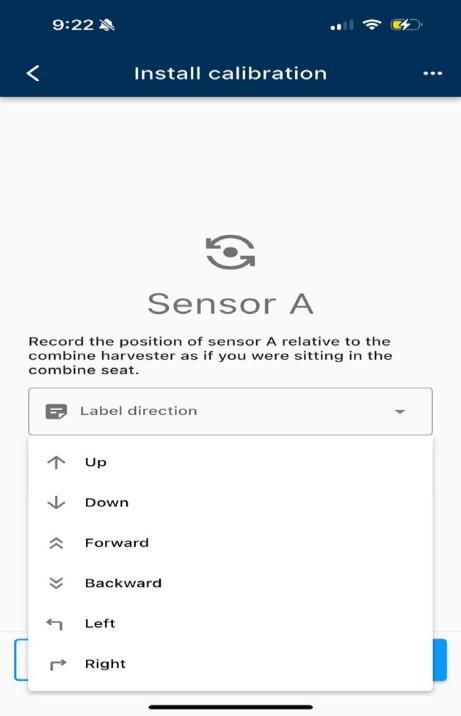
For example, in the image below, Sensor A is mounted with label facing Right, and connectors facing backward. Sensor B is mounted with label facing up, connectors backward.
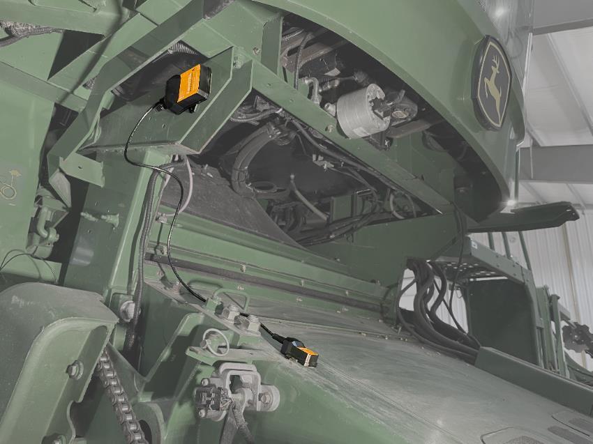
6. Follow the same steps for Sensor B, selecting the relevant label and connector directions using the same criteria as Sensor A.
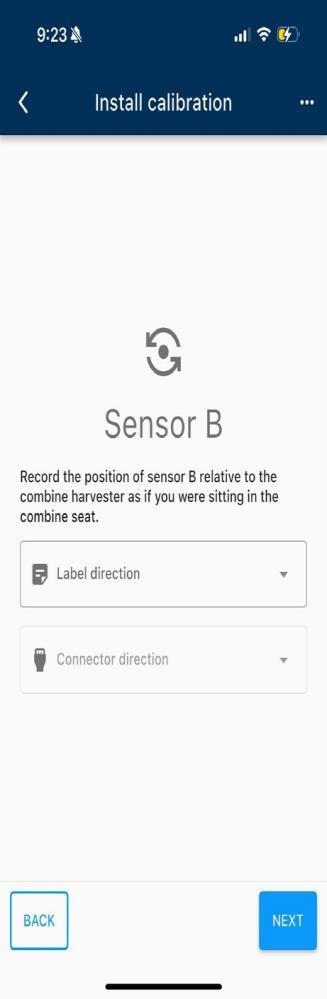
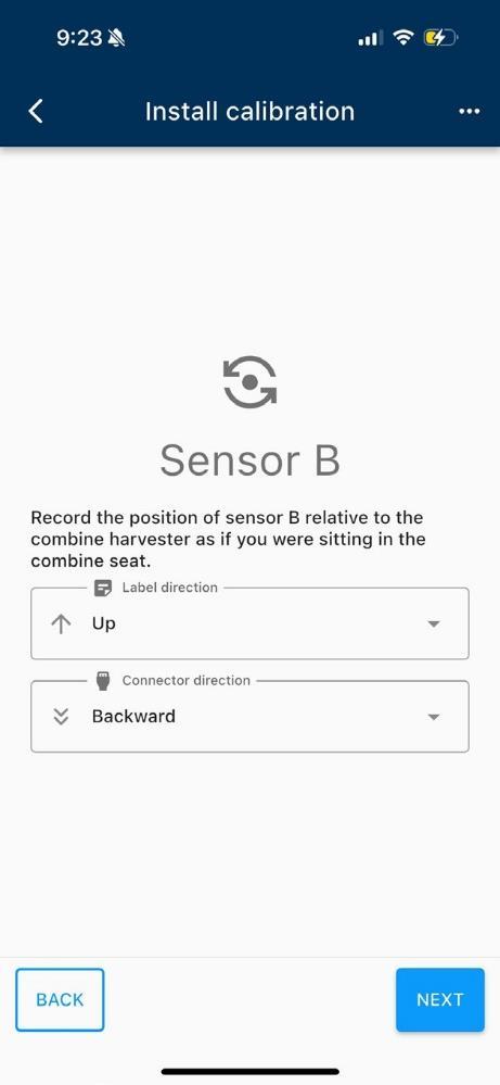
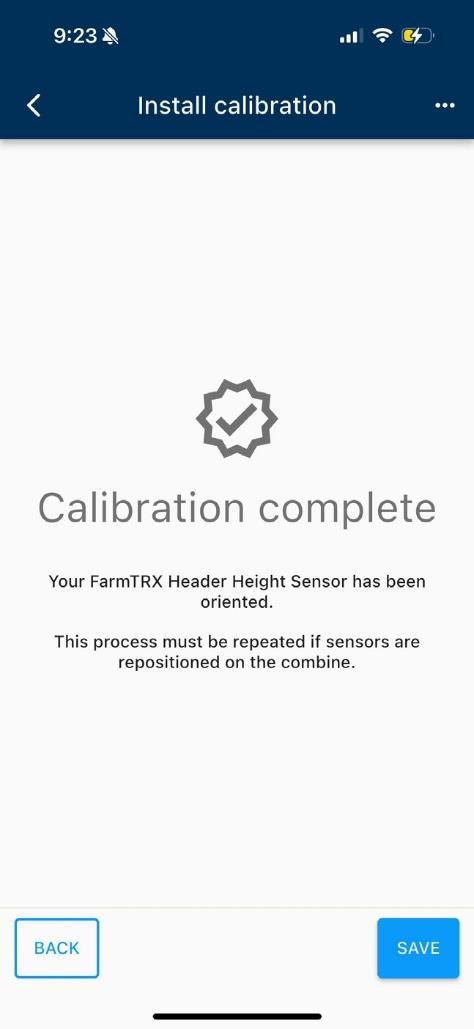
7. Sensor orientation is now complete, if successful you will see the following screen. Press “Save Calibration” to save and return to the main screen.
Header Calibration
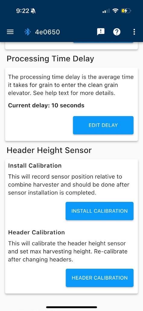
This stage will calibrate the Header Height Sensor and establish a max cutting height. You may need to repeat this step if you change headers. For example, switching from a platform header to a corn head, the max cut height will need to be re-calibrated. A tape measure is required for this step.
1. Select Header Calibration from the main menu.
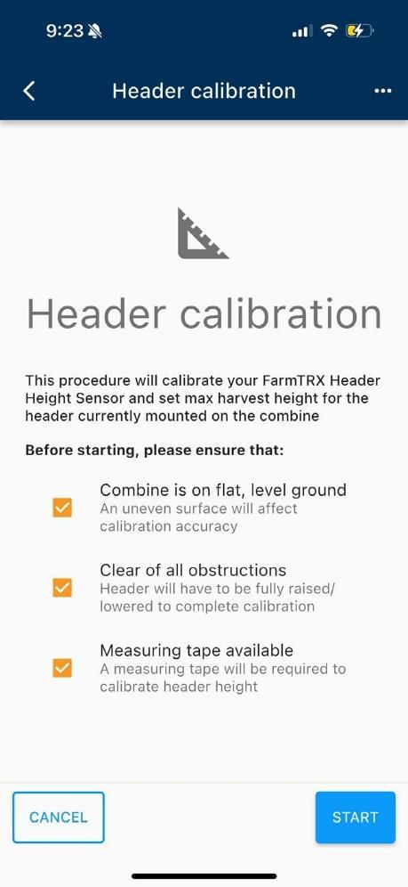
2. Follow the instructions in the app and lower the header until it just touches the ground. Do not push the header into the ground as this will affect the accuracy of readings.
3. Press “Next” once the header is just touching the ground.
4. Raise the header as high as possible
5. Measure the distance from the ground straight up to the cutter bar and enter the value into the app.
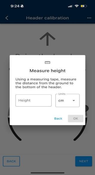
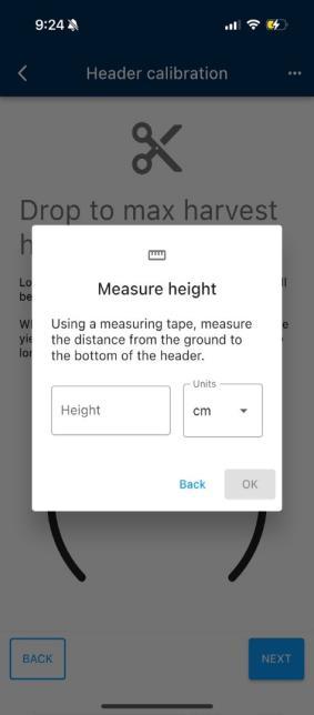
6. Lower the header to the maximum cutting height while harvesting. Any time the header is raised above this level, the areawill stop countingin the Yield kit App. Once at max cut height, measure the distance from the ground to the cutter bar and enter the value in the app.

7. Press “OK” and “Save”
Operation
While harvesting, you can change one of the tiles of the live harvesting screen to the “Header Height” tile. This will show the active cutting height of the header. A green border will be present when the header is below the max harvesting height threshold.
Setup in FieldView Cab App
Once the Head Height Sensor is oriented and calibrated in the Yield kit App you are ready to set max harvest height in the FieldView Cab App. To watch a YouTube video, scan the QR code:

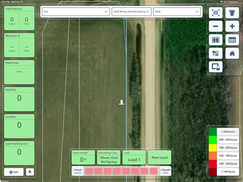
1. Click on Head Height tile to get started
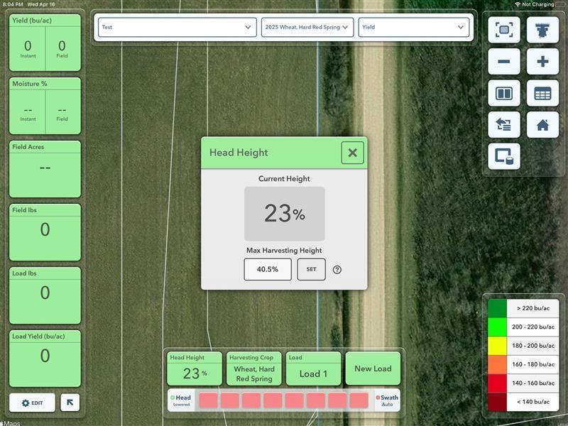
2. Then Click on “Set”
3.
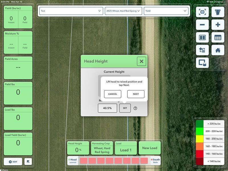
Lift head to fully raise position and click next.
4. Lower the head to just above the maximum height you will be actively harvesting then click done.
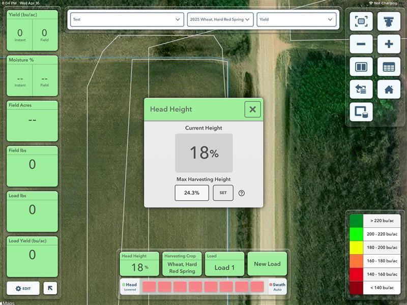
5. Your max harvest Height is now set in FieldView Cab App
Troubleshooting
- App won’t let the orientation process complete
o Incorrect label/connector direction has been selected in the app. Repeat process and ensure the direction of the sensor label and connectors are properly chosen
o Combine is on uneven surface and there is too much pitch/roll
o The sensor body does not have one axis parallel to the wheel axle
- Area not counting in the app while actively harvesting
o Max harvest height threshold was set too low. If the header is lifted above the max harvesting height threshold established during the header calibration process, area will not be counted. To fix, re-do header calibration and set a higher max harvest height
- No readings from head height sensor
o CANbus error. Check that all wires are properly connected and the colour of CANbus LED on Sensor A. If red there is a CAN fault. Disconnect wires and reconnect, ensuring properly CAN terminators are attached.
o Sensor wire connecting Sensor A to Sensor B is not making good connection. Power down system, disconnect sensor bodies from sensor wire, re-connect, then re-power system.
Interpreting LEDs
LABEL COLOUR STATUS
“SENSOR”
“CANBUS”
White Sensor not calibrated
Green Below max harvest height
Blue Above max harvest height
Orange Roll too high
Yellow Out of calibration range
Red Error
Green System normal / Green/Blue Transmitting data
Yellow Warning
Red CANBUS fault
“RADIO”
Off Not connected over bluetooth
Blue Connected over bluetooth
RECOMMENDED SOLUTION
Navigate to the device calibration page in Yield kit mobile app and perform Install Calibration and Header Calibration
Check that sensors are still properly installed, re-do calibrations.
Check that sensors are still properly installed, re-do calibrations.
Check that Sensor A is properly connected to Sensor B.
Check that CAN terminators are installed.
Check the harnesses and make sure wires aren’t chafed or shorted out.