H
2.0
H
H
H
H
L Faculty: Nick. Bruscia
2.0 4.0
Nida Ali L
L
2.0
H
H
L
H
L
12.0
L H
H
L
H
H
H
L
4.0 H
2.0
2.0
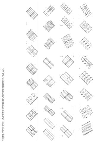
The System works with two conditions: H L curves Land I folds. FocusL on the edge and center sections of the continuous surface, H not only introduces strength and stiffness to the system, butL also adds flexibility to H H H L it.
H
L
H
L
4.0
H
2.0
2.0
2.0
L
4.0 2.0
L
H
H
H
H
L
L
L
H
L
D
4.0 2.0
H
H
2.0
L
L
2.0
2.0 2.0
4.0
H
H
L
L
H
L
2.0 4.0
H
D
L
L
4.0 H
LH
4.0 L
HH
H
H
4.0 H
H
L
L
L
H 4.0
2.0 H
H
4.0 L
2.0
L
4.0
L
H
4.0
L
L
L
H
L
2.0 4.0
H
L
C
H
4.0
1.0
H
4.0
L L
L
L
L
4.0
C 4.0
L
L
L
H
L
H
H
H
H
H
H
2.0
1.02.0
L
1.0
H
1.02.0
L
H
2.02.0
H
L
H
H
L
2.02.0
1.0
H
H
L
6.0
H
L H
L H
H
L
0.5
H G
L
L 2.0
L
H
H
B
L
12.0 1.0 12.0
D
Flexible Architecture -Situated Technologies Graduate Research Group 2017
C
L
H
H
1.0
2.0
L
H
2.0
4.0
2.0
1.02.0
1.0 2.0 1.0 2.0 1.0 2.0 1.0 1.0 1.01.0 1.0 1.0 1.0 1.0 1.0 1.0 1.0 1.01.0 1.0 1.01.0
6.0
12.0 12.0 L
4.0
H
H
H
H
C
H
L
2.0
H
1.0
2.0
H L
H
L
6.0
L
L
2.0
L
H
L H H
H
H
A
4.0
2.0
H L
H
2.0
H
L
H
L
L
L
L
C
L
12.0 10.0
2.0
L
G
2.0
H L
2.0
GH
4.0 2.0
H
L H
L
H
GL
L
L H
L
4.0
H
B
H
H
L
L H
H
L
H
L
L
L H
L
H
H
H
4.0
H
H
L
H
2.0
L
L H
H
L H
L
L
H
L H
H
L H
H
F
L
L
E
H
L H
B
L H
L
H
B 10.0
H
L H
2.0
L H
H
L
L H
L
L
2.0
H
L H
H
L H
L
L H
L
L H
A
L H
2.0
L
H
L
4.0
1.0 5.0
L
H
1.0
L
H
H
H
H
H
L
H
L
4.0
L
L
H
H
H
H
4.0
H
H
L
H
H
3.0
5.0
A 1.0
E
H
H
L H H L
L H
L
L H
H
H L
B
L
L H
F
F
A 1.0
H
H
10.0
L
2.0
H
2.0
H
L
L H L
L
L H
L
L H
H
L H
H H
5.0
L H
H
H H
L L
L
H
H
L L
H
L
L H
H
L H
L
L H
A
L
H
5.0
E
H
L
H
L
F
2.0 2.0
L
L
H H
2.0
L
2.0
H
2.0
L
L
10.0
L
H
10.0
L
H
LH
B
H
L H
L
L H
H
L H
H
L H
L
L H
L
L L H
H
H
L
1.0
L H
1.0
2.0 2.0
L
5.0
H
L
L H
H
L
L
L
1.0
L
H L
L 2.0
H L
2.0
HH H L
H
H H
L
L
H
H
L
H
E
L
L H
H
L
L
H
H
H H
L
H
H
H
L H
L H H
L L
L
L H
H
H
H L
1.0
L
1.0
10.0
5.0
0
H
L
L
10.0
H
L
A
H
L L
L
H
L
2.0
2.0
H
L
H
1.0
H
1.0 H 1.0 1.0 1.0 1.0 1.0 1.0 1.0 1.0 1.0 1.0 1.0 1.0 1.0 1.0 1.0 1.0 E 1.0 1.0 1.0
H
4.0
L
2.0 L
H
L
H
H
L
H H
H
F
L
F
H
4.0
L
L
H
L H
2.0
H
L
L
H
L
H
L
H
L
H
L
2.0 H
L
H
H H
2.0
H
L
H
H
H
H
2.0
H
4.0
L
2.0 L
H
L
L
1.0 1.0 1.0 1.0 1.0 1.0 1.0 1.0 1.0 2.0 1.0
2.0
L
L
H
L
L
2.0
L
L
H
H
L
F
H L
L H
H
H
HH
H L
L
H
4.0
H
L
1.0
L
L
1.0
H
4.0
L
L
H
L
L
L
H
H
H
L H
L
L
E
H
H
L
L
H
H
L
L
H
H
L
L
L
H
L H
1.0
H
1.0
L L
1.0
H
L
H
H
L
L
H
L H
L
L
H
H
H
1.0
H
L
H
H
L
LH
H
L
2.0
H
L H
L
L
H L
2.0
L H
H
H
H
H
L 2.0
H H
L
H
2.0
H
L H
L
L
H
2.0
LL
H L H
L
H
2.0
H
2.0
H
L H
H
L
L
H 2.0
H
L
1.0 1.0 1.0 L L 1.0 H 1.0 H 1.0 1.0 L L 1.0 H 1.0 H 1.0 1.0 L L 1.0 H 1.0 H 1.0 1.0 L L 1.0 H 1.0 H E 1.0 1.0 H
H
L
L
L
2.0
L
4.0
L
2.0
L H
H H
H
L H
L H
2.0
2.0
H
L
1.0 L 1.0 H 1.0 1.0 L 1.0 H 1.0 L 1.0 1.0 H 1.0 L H 2.0
H
10.0
2.0
2.0
L
2.0
H
2.0 2.0
H
L
H
HH
L
L
H
L
L
L
L
2.0
L
H
2.0
H
H
L
2.0
L H
L
H
L
H
2.0 L
H
L
2.0
L
0
L
2.0
L
H
2.0
L
H
LH
H
H
H
1.0
L
L H
L H
H
2.0 H
H
1.0
L
2.0
H
2.0
H
L
H
L
2.0
H
2.0
L H
L
H
H
L
H
L
L
2.0
2.0 L
LL
H
L
H
H
L
L
H
H
H
H L
H
G
H
2.0
H
2.0
H
H
2.0
L
L H
2.0
L
L
H
L H
H
1.0
10.0
H
12.0 10.0
2.0
L
L
1.0
5.0
L
12.0 L 10.0
H
H H
L
1.0
L
3.0 E
1.0
1.0
H
H
L
1.0H
1.0
L
L
L
1.0
H
L
H
1.0
L
L
H
LH
L
H
1.0
H
L
L
L
2.0
H
H L
L
L
H
4.0
H
L
2.0L
L
L
L
L
L
L
4.0
H
H
H
5.0
L H
H
L
L
L H
2.0
4.0
H
H
L H
H
H
2.0
L
L
F
L
4.0
H
L
H
L
1.0
2.0
H
L
L
L
1.0
H
L
H
6.0
1.0
2.0
H
L
L
L H
4.0
H
L L
L
2.0
L L
L H
L H
H
H
H
2.0
L
H
H
H
L
L
L
2.0
2.0
H H
2.0
H
2.0
L
H
L H
H
L
H
L
L
L
H
H
H
2.0
H
L
2.0
H
L
L
H
H
H
2.0
L H
L
H
L
2.0
L
2.0
HL
H
L
H
H
2.0
2.0
L
H
H
H H
L
L
2.0
H
L
2.0
L
L
H
H L
H
H
L
L L
F
L
H
L
L
L
1.0
2.0
H
L
H
2.0
H
H
L 12.0 10.0 H
H
H
L
L H
L
H
2.0
H
L
L
2.0
L
L
L
2.0
H
L
H
L
L
H
2.0
H
2.0
L
H
H
L
H
H
L
G
H
H
H
2.0
H
2.0
L H
2.0
H
HL
H
H
H
H
2.0
L
H
H
2.0
H
L
L
L
2.0
L
L
L
H
H
1.0
L
L
L
H
L
L
L
H
4.0
H
1.0
L
L
2.0
L
H
L
2.0
H
H
H
H
2.0
L
6.0
L
H
2.0
H
H
6.0
H
1.0
H
2.0 H
H
2.0
2.0
L
H
2.0
L L
L
G
L
H
L
H
L
2.0
H
L
L
L
L
2.0
HH
6.0
L
4.0
L L
H
L
2.0
L
H
H
1.0
CH
L
2.0
H L
H
H
L
L
2.0
L L
L
12.0 12.0
L
L
H
L
1.0
H
H
2.0
L
L
H
H L
H
H
2.0
H
H
2.0
H
L
H
4.0
H
L
H
L
0.5
H
L
L
H
L
H
L
L
2.0
L
L
L
H
L
H
L
H 4.0
H
H
12.0 12.0
L
L
H
4.0 H
L
2.0
H
H
L
2.0
H
L
L
H
H
L
G H
H
H
L
L
L
2.0
L
2.0
2.0
H
L
L
L
H
L
L
4.0 L
H H
H
L
G
L
2.0
H
L
H
4.0
H
H
L
L
L L
H
H
H
4.0 H
4.0
L
L
H
H
L
L L
H
1.0
L
2.0
H
L
L
H
L
2.0
2.0 H
L
H
H
L
H
H
4.0
H
L
1.0
4.0
H H
L
L
L H
H
H
2.0
H
H
H
H
H
L H
2.0
C
L
L
L
L
2.0 2.0
L
L
H
1.0
H
L
L
2.04.0
1.0
H
L
4.0
H
H
H
1.0
L
L
H 4.0 L
H H
L H
H
2.0
H
4.0
2.0
H
L
L
2.0
H
L
L
L L
H
L
L
H
4.0
L
H
L
H
H
A
L
L
H
L
2.0 4.0
2.0
H
L
2.0 2.0
2.0
L
H
4.0
H
H
6.0
H
H
4.0
2.0
H
1.0 2.0
1.0
L
C 1.0
H
1.01.0
H
2.0 L
L
HH
H
L
1.01.0
2.0 4.0
L
1.0
L
L
1.01.0 C 1.01.0
H
L
B 2.0
L
H
1.0
H
L
H
H
H H
L
H
H
4.0
H 4.0
LL
L
H
H
4.0
L
4.0
H H
L
L
L
H
L
L
H
H
L
4.0 2.0
L
2.0
H
L
L
L
H
H
L
L
H
2.0
H
L
L
1.0
H
H
L
2.02.0
4.0
L
L
L H
H L
H
L
2.0 L
H
1.0
4.0
H
L 4.0
2.0
L
H
H
L
L
2.0
2.0
H
H
H
H
H
L
4.0
L
L
H
4.0
H
H
H
L
H
L
2.0 H
4.0
H
H
2.0
H
L
L
L
H
L
2.0
4.0 L
L
H
L
L
H
H
H
L H
H
L 4.0
H
2.0
L
H H
H
L
H
H
L
2.0
L
L
H
H
L
L
H
H
H
L
H
2.0
H
L
2.0
L
L
L H
H
H
L
L
2.0
H
4.0
H
L
L
H
4.0
H
H
H
L
H
L
2.0
H
L
L
L
H
H
L
2.0 L
4.0
L
2.0
L
H
H
L
L
H
L
H
H
H
H
H
L
H
D
H
H
HH
H
4.0
H
H
H
L
H
2.0
H
L
L
H
L
H
L
L
H
L
L
4.0
H
H
L
H
L
L
L
L
L
L
L
L
4.0
H
H
L
H
L
H
H
L
L
H
H
H
L
L
H
4.0
H
2.0
L
L
L
H
H
H
H
L
L
L
L
H
L
L
H
L
H
H
L
L H
H
H
L
H
L
4.0
H
L
L
H
L
L
L
2.0
H
H
H
H
2.0
L
H
H
L
L
H
4.0
L
H
L
4.0 L
H
L
L
H
L
H
H
H
L
H
L
4.0
H
L
D
D
2.0
L
2.0
H
L
H
I 4.0
H
L
L
H
L
2.0 H
LH
L
H
H
H
H
H
L
L
H
4.0 H
L
H
L
L
H
2.0
D
H
H
L
H
2.0
H
H
H
L
L
4.0
L H
L
L
L
2.0
L
Section
L
L
2.0
L
L
H
4.0 L
L
2.0
L
H
H
H
H
H
H
H
L
H
L
H
L
H
L
H
H
4.0
H
L
H
H
H
L
H
2.0
H
2.0
L
L
The System reacts with external and internal loads. Voids are embedded within L the system to explore permeation of light, H potestion againstH windL and water withinL L the form. L
L
H
4.0
L
L
L
L
L
L
L
L
2.0
H
H
12.0
H
L
I 4.0
H H
H
H
H
H
L
H
H
L
4.0
L
4.0
I
H
2.0
Convex and Concave curves are oriented a H L L different axis inH relation to the folds,L transfrming the form of the continuous H surface.
H
L
L
L
H
L
H
4.0
H
2.0
4.0
L
H
L
L
2.0
12.0H
4.0
H
L
L
L
H
H
H
2.0
L
H
L
L
L
2.0
H
L
H
2.0
H
H
L
L
12.0Group 2.0 Situated Technologies4.0 Research Studio, Fall 2017 - Flexible Architecture
4.0
L
2.0 2.0
H
1.0
2.0
2.0
1.0 L
1.0
L
1.0
H
E
1.0
H
1.0
L
1.0
H
L H
1.0 1.0
H
H
H
L
L
H
H
L
H
L
H
L
H
H
H
L
H
1.0
H
H
L
L
H
H
L
H
H
H
L
L
H
H
L
L
L
H
L
L
L
1.0
1.0
Situated Technologies Research Group Studio, Fall 2017 - Flexible Architecture
2.0
4.0
Faculty: N. Bruscia
4.0
12.0
L
4.0
H
12.0
4.0
2.0
H
L
L
H
Nida Ali 4.0
The System works with two conditions: curves and folds. Focus on the edge and center sections of the continuous surface, not only introduces strength and stiffness to the system, but also adds flexibility to it.
4.0
I 4.0 H
L
L
H
H
L
L
H
H
L
4.0
Convex and Concave curves are oriented a different axis in relation to the folds, transfrming the form of the continuous surface.
4.0
The System reacts with external and internal loads. Voids are embedded within the system to explore permeation of light, potestion against wind and water within the form.
Section
I
4.0
4.0
D
D
4.0
4.0
H
L
4.0 H
H
4.0
4.0
4.0
L
2.0 2.0
4.0 D
4.0
H
2.0
I
4.0
L
4.0
H
L
2.0
4.0
L
H
4.0
H
2.0
L
2.0
4.0
L
C
C 4.0
1.0
H
4.0
4.0
H
2.0
L
4.0
L
2.0
H
H H
2.0
H 4.0
L
4.0
L
D
C
I
2.0
L
H
H
2.0
12.0 12.0
H
12.0 12.0
H
B
B
H
2.0
L
2.0
H
2.0
L
2.0
L H
2.0
H
L
1.0
H
1.0
2.0
H
L
H
4.0
2.0
2.0
L
2.0
H
2.0
L
2.0
H
2.0
L
H
B 4.0
L
G
H
L
12.0 10.0
2.0
12.0 10.0
H
2.0
H
L
2.0
H
2.0
L
2.0
H
L
L
2.0
H
2.0
L
2.0
H
H
2.0
L
L
2.0
H
H
2.0
H
H
2.0
L
L
H
H
H
F
H
10.0
10.0
B L
H H L
A
L
F
L
2.0
L H
E
H
4.0
1.0
H
4.0
H H
L L
2.0
1.0 1.0 1.0 1.0 1.0 1.0 1.0 1.0 1.0 2.0 2.0
L
2.0
L
2.0
H
2.0
1.0
L
L H H
4.0
2.0
4.0
L L
1.0 1.0 1.0 1.0 1.0 1.0 1.0 1.0 1.0 1.0
H H L L H H L L
E 3.0
1.0
H H
3.0 10.0
0
10.0
2.0 2.0
H
E
2.0
H H
2.0
A
2.0
H
2.0
2.0
F
2.0 L
4.0
2.0
H
L
4.0
2.0
L
H
4.0
2.0
2.0
L
4.0
2.0
L
H
G
G
H
L
4.0
2.0
H
H
A
2.0
L
L
A
2.0
H
L
C
2.0
L
2.0
4.0
2.0
H
H
F
2.0
L
1.0
G
2.0
H
1.0 H
2.0
L
L
1.0
2.0
L
L
2.0
4.0
H
1.0 1.0 1.0 1.0 1.0 1.0 1.0 1.0 1.0 1.0 1.0 1.0 1.0 1.0 1.0 1.0 1.0 E 1.0 1.0
H
2.0
Situated Technologies Research Group Studio, Fall 2017 - Flexible Architecture
1.0
2.0
2.0 H
H
2.0 L
L
2.0
H
H
H
L
L
L
H
H
H
L
L
L
H
H
H
L
L
H
H
L
L
H
H
L
L
H
H
4.0
H
H
L
H
2.0
L
Faculty: Nick. Bruscia
Nida Ali
The System works with two conditions: curves and folds. Focus on the edge and center sections of the continuous surface, not only introduces strength and stiffness to the system, but also adds flexibility to it. Convex and Concave curves are oriented a different axis in relation to the folds, transfrming the form of the continuous surface.
2.0
H
H
H
2.0
L
L
L
2.0
H
H
H
2.0
L
L
L
2.0
H
H
L
H
L
H
L
H
H
H
L
H
L
L
L
L
L
H
H
L
L
L
H
H
H
L
H
L
H
L
L
2.0
L
2.0
H
2.0
H
L
2.0
L
2.0
H
The System reacts with external and internal loads. Voids are embedded within the system to explore permeation of light, potestion against wind and water within the form.
2.0
2.0
2.0
L
L
L
H
H
H
L
L
L
H
H
L
H
L
H
L
H
L
H
H
L
L
H
H
D Section
D
2.0
4.0
L
L
H
H
L
L
H
H
L
L
H
H
H
L
H
H
2.0
L
H
H
L
L
2.0
L
H
H
2.0
H
L
L
2.0
L
H
H
2.0
D 2.0
H
H
H
2.0
L
L
L
H
H
H
2.0
H
H
H
L
H
H
L
H
L
L
L
L
H
H
L
L
L
L
H
H
L
2.0
2.0 L
L
H
L
H
L
4.0 H
H
H
H
L
L
4.0
H
H
L
L
L
L
2.0
L
L
H
L
2.0
H
H
H
L
H
L
L
H
L
H
L
H
H
H
H
H
H
H
L
L
H
L
L
L
H
L
H
L
H
H
H
L
H H
4.0 H
H
2.0
H G
H
L
2.0
1.0
L
L
L
1.0
H
H
H
1.0
L
H
L
1.0
H
H
L
2.0
H
H
C 1.0
H
L
2.0
H
H
L
2.0
H
H
L
L
L
1.0
H
H
L H
L
H
L
L
L
H
L
H
L
H
L
0.5
L
H
G C
H
6.0
L
2.0
H
L
1.0
L
H
6.0
L
1.0
C
C
1.0 1.0 2.0
H
L
L
L
L
L
L
6.0
2.0
4.0
L
H
4.0
L
H
6.0
1.0
L
H
L
H
L H
2.0
H
L
2.0 2.0 4.0
L H
L
L
H
L
L H
H
L H
L
L
H
L
H
L
F
H
L
L
F
H
H
B
H
H
H
L
L H H
L
5.0
H
L H
L H
1.0
L
5.0
H
L
L H
2.0 H
H
L
1.0
L
L
1.0
1.0
H
H
H
H
L
L
1.0 1.0
E
H
H
H
L
L
H
H
H
L
H
H
L
1.0
L
L
L
H
H
L
H
H
L
L
H
H
L
L
H
L
L
1.0
L
H
1.0
H
H
1.0
L
L
H
H
1.0
H
1.0
H
L
L
H
L
H
L
E
H
H
H
H
L
H H
L
L
H
L H
5.0
L
L
1.0
H
L
L
L
H
H
L
L
1.0
E
1.0
H
H
L
L
H
L
L
H
L
4.0
L
L
L
L
L
H
L H
L
H H
H
H
H
H
L
L
L
L
1.0
1.0
L
4.0
L H
L
H
L
A 1.0
L
L
H
H
L
H
1.0
1.0
A
H
L
H
H H
2.0
L
L
4.0
H H
L
H
L
2.0
H
H
H L H
H
H
L
H
L H
H
2.0
L
L
L
L H
L
L
L H
H
L
L H
H
4.0
H
L
L H
L
1.0
4.0
H
H
L
L H
L
L
H
L H
1.0
4.0
H
H
H
L
H
1.0
4.0
L
L
L H
L H
L
H
2.0
H
L
L H
H
A
2.0
L
L H
L
B
L
H
2.0
L
H
2.0
H
H
L
B
2.0
H
H
H
E
H
L
H
L H L
L
L
2.0
H
H
H
H
H
L
L
L L
2.0
L
L
L
H
L
L
H
L
H
H
H
F
L
H
L
H
2.0
H
H
L
H
H
L
L H
H
L
H
H
L
2.0
L
L
H
H
2.0
H
L
H
H
L
1.0
L
H
L
H
1.0
L
L
L
L
L
H
1.0
H
H
L
1.0
L
H
L
4.0
L
H
2.0
L
H
L
L
2.0
H
L
H
4.0
L
L
H
H
H
L
B
H
L
H
L
H
H
L L
L
4.0
L
L
H
H
F
H
L
L
L
C
2.0
H
H
H
H
H
4.0
L
H
H
L
H
G
2.0
L
H
H
H
H
2.0
L
H
L
H
H
H
L
L
H
2.0
H
L
L
G
H
L
H
H
H
1.0
2.0
H
L
H
H
L H
L
L
H
H
2.0
L
H
H
2.0
L
H
L
L
1.0
1.0
L
L
L
H
1.0
L
H
L
H
1.0
H
L
H
L H
2.0
H
H
2.0
H
L
L
L
H
L
L
H
H
D
2.0
H
H
L
2.0
2.0
2.0 H
4.0
H
L
L
L
L L
L
H
H
L
2.0
L
4.0
H
L
L
L
L
H
L
H
4.0
L
A
H
H
L
H
L
H
H
5.0
1.0
1.0
1.0
1.0 1.0
Situated Technologies Research Group Studio, Fall 2017 - Flexible Architecture Faculty: N. Bruscia
Nida Ali Exploration of modules and creating seamless connections between the modules to form continuous surfaces. To investigate material possibilities and limitations within the folded and corrugated system. Analyzing the shift or offset of the module in the X and Y axis of the system, to strengthen it or add felxbility to it, while considering the materials inherent property of strength and flexibility. Material and Form Exploration Fold an dcorrugatiion sudy Figure 1 Material: Wet Stonehenge Paper Analysis: Strength introduced by folds in the center, Flexibility and weakness along the corrugation lines. Figure 2 -
Figure 1.
Matrial: Matboard Analysis: Stiffness and strength along the corrugation lines. Folds are less prominent due to stiffness of the material. Figure 3 Matrial: Wet Mounting Board Analysis: Stiffness and strength along the corrugation lines. Folds are prominent and add to the strength of the system, flexbitility increases towards the outer edges. Figure 4 Material: Stonehenge Paper Analysis: Strength introduced by folds and pleats along the form. Flexibility and weakness inherent within the material and along the corrugation lines..
Figure 10.
Figure 5 Material: Plastic Mesh + Resin + Felt Fabric Analysis: Strength introduced by folds and pleats along the form. Plastic Mesh adds to the strength and flexibility of the system while the fabric and resin force the mesh to retain the form. Figure 5. Figure 6 Material: Wet Plywood Analysis: Strength introduced by folds and by the material itself. Wetting the plwood makes it flexible, allowing it to take the form when dry. Difficult to take form of the folds in the center, due to scale of the model and curvature of the form. Figure 7 Material: Aluminium sheet Analysis: Strength introduced by corrugation and by the material itself. Low Flexibility due to material strength and scale of the form.
Figure 2.
Figure 8 Material: NewPaper + Glue (Paper mache) Analysis: Strength added due to thickness of the material and glue. Center folds introduce the most amount of strength within the system whereas the corrugation towards the ends introduce some flexibility. Figure 9 Material: Moldable Plastic + Wire Mesh + Resin Analysis: Strength added due to Moldable plastic, whereas the resin adds strength and acts as a binding agent between the wire mesh and plastic. No flexibility in the form due to plastic. Figure 10 Material: Plastic Mesh + Resin Analysis: Flexibility added due to Plastic mesh, the resin forces the Plastic Mesh to retain the shape of the form, reducing its flexibiliy but adding to its strength. Figure 11 Figure 6.
Material: Fiberglass Screen + Felt + Resin Analysis: Fiberglass screen adds to the flexibility of the system, felt being relatively rigid compared to the screen adds to the strength while the resin acts as a binding agent. Wasnt able to hold form. Figure 12 -
Figure 11.
Material: Wire Mesh + Felt + Resin Analysis: Flexibility and Strength due to wire mesh, the resin forces the Mesh to retain the shape of the form, reducing its flexibiliy but adding to its strength. Felt binds the resin and Mesh together. Wire mesh is still flexible, resistence to taking the shape of the form.
Figure 7.
Figure 3.
Figure 8.
Figure 4.
Figure 9.
Figure 12.
Situated Technologies Research Group Studio, Fall 2017 - Flexible Architecture Faculty: N. Bruscia
Nida Ali Kevin Turner Material Production Process The material is cast, laid, or formed over a mold with the desired corrugation pattern. Multiple layers of Matrix material and Reinforcing Fibers are laid over one another to build up the material surface. Given the properly configured mold, this process can perform as a Slip Cast, allowing for surfaces of indefinite size to be made by moving the mold and aligning corrugations together and casting the next section.
Fig 6. Strand Alignment Reinforcement Fibers
Matrix Material
Fig 1. Mold Form A
Post Tensioning Wires
Fig 7. XXXXX
Fig 2. Mold Form A
Fig 8. XXXXXX
Fig 5. Mold Press Layering
Fig 3. Mold Form B
Fig 4. Mold Form B
Fig 9. Aggregate Slip Cast Process
Situated Technologies Research Group Studio, Fall 2017 - Flexible Architecture Faculty: N. Bruscia
Nida Ali Kevin Turner
Fig 1. Corrugation Type A - Simple Offset
Fig 2. Corrugation Type A - Simple Offset
Fig 7. Folding Progression in Standard Corrugation
Fig 3. Corrugation Type B - Scale Shift
High Folding/Deformation
Fig 4. Corrugation Type B - Scale Shift
Slight Deformation
Stable Corrugated Form
Fig 5. Corrugation Type C - Fold Point Scale
Fig 6. Corrugation Type C - Fold Point Scale
Fig 8. Folding Stress Diagram
Situated Technologies Research Group Studio, Fall 2017 - Flexible Architecture Faculty: N. Bruscia
Nida Ali Kevin Turner Exploded Section Oblique 5HLQIRUFHPHQW ÀEHUV DUH ODLG LQ D UDGLDO pattern about the bend points in the material. Strand orientation correlates with stiffness needs of material at various points along the surface. Bend points XVH FRQQHFWLQJ ÀEHUV DOLJQHG LQ WKH same direction suited to bending in one direction, while stiff corrugation areas us a GLDJULG RI RYHUODSSLQJ ÀEHUV IRU LQFUHDVHG stiffness and rigidity The corrugation varies its depth along its length. High-stress areas are thicker to provide resistance and maintain desired corrugation form in bending Deep corrugation areas require less material, as the form provides needed structural support.
Section 01
Section 02
Section 03
Fig 2. Reinforcement Fiber Pattern
Fig 3. Post Tension Cable Arrangement
Section 03
Fig 1. 0DWUL[ 0DWHULDO &RQÀJXUDWLRQ
Section 02
Section 01
Key Plan