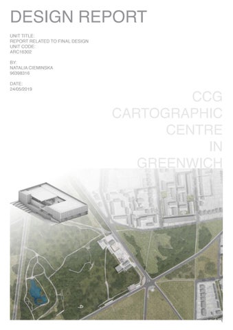
DESIGN REPORT UNIT TITLE: REPORT RELATED TO FINAL DESIGN UNIT CODE: ARC16302 BY: NATALIA CIEMINSKA 96398316 DATE: 24/05/2019
CCG CARTOGRAPHIC CENTRE IN GREENWICH
1
CONTENTS PAGE PART 1: Design Process (RIBA Stages 0, 1, 2 and 3)
1.5.4 Maggie’s Oldham ....................................................................................................
Selecting the Site, Preparation and Brief (RIBA Stage 0 and 1)
1.5.6 Physical Models of site and 3D zoning..........................................................................
1.5.5 Auditoriums...............................................................................................................
1.5.7 Excavating mindmap..............................................................................................
1.1 The site..................................................................................................................................
1.5.7.1 Danish Maritime Museum..................................................................................
1.1.1 Introduction to the site and project..............................................................................6-7 1.1.2 History of the site...........................................................................................................8-9 1.1.3 Local materiality and context.....................................................................................10 -11
Concept Design and Applying for Planning Permission (RIBA Stage 2) 2.1 Feasibility study ..................................................................................
1.1.4 Aerial views of the site...........................................................................................................12-15 1.1.5 Site area ....................................................................................................................16-17
2.2.1 Development sketch..................................................................................
1.1.6 Plans of the site..........................................................................................................18-21
2.2.2 Initial spaces arrangement..................................................................................
1.1.7 Sectional elevations.....................................................................................................
2.2.3 Connections between floors.................................................................................. 2.2.4 Building features development....................................
1.2 Site Analysis ........................................................................................................................ 1.2.1 Exsting site usage and access....................................................................................
2.2.5 Design Inspiration..................................................................................
1.2.2 Immediate context........................................................................................................
2.2.6 Application of Part M regulations..................................................................................
1.2.3 Site characteristics.......................................................................................................
2.2.7 Different iterations of design..................................................................................
1.2.3.1 Greenery/water and topography....................................................................
2.2.8 Physical model exploration..........................................................................................
1.2.3.2 Nolli and roads/paths....................................................................................
2.3 Final Concept Spatial Breakdown..................................................................................
1.2.3.3 Points of interest and landuse........................................................................
2.4 Professions, Role, and Legal Bodies Involved......................................................................
1.2.3.4 Transport links and main circulation...............................................................
2.4.1 Roles and responsibilities........................................................................................
1.2.3.5 Meteorological data........................................................................................
2.4.1.1 Architect and contractual relationship to client.........................................
1.2.3.6 Sun and wind diagram...................................................................................
2.4.1.2 Principal Constructor................................................................................
1.2.4 Demographics........................................................................ ...............................
2.4.1.3 Quantity Surveyor/Cost Consultant...........................................................
1.3 Client(s), user(s), and funding..................................................................................
2.4.1.4 Other consultants...............................................................................................
1.4 Initial proposed programme.....................................................................................
2.4.1.5 Building Control Officer.....................................................................................
1.5 Initial concept narrative and precedents..................................................................................
2.4.1.6 Contractor..................................................................................
1.5.1 Cartography research..................................................................................
2.4.1.7 Sub-contractors..................................................................................
1.5.2 The Hepworth Wakefield..................................................................................
2.4.2 Principal Constructor..................................................................................
1.5.3 Working with existing walls ..................................................................................
2.4.3 Structural Engineer ..................................................................................
1.5.3.1 Warwick Hall Community Centre ...................................................................
2
2.4.4 Environmental or Services and Sustainable Engineer.........................................
3
2.4.5 Planning Consultant..................................................................................
6.Appendix
2.4.6 Lanscape Architect..................................................................................
7. Conclusion
2.5 Legal Bodies ..................................................................................
8. Bibliography
2.5.1 Local Authority Planning Department........................................................................... 2.5.2 Planning Officer.................................................................................. 2.5.3 Conservation Officer.................................................................................. 2.5.4 Planning Committee.................................................................................. 2.5.5 Construction, Deisgn & Management........................................................................... 2.5.6 Health & Safety Executive.................................................................................. 2.5.7 Regulations....................................................................... 2.5.7.1 Part B means of escape in case of fire...................................... 2.5.7.1.1 Application to my design............................................................... 2.5.7.1 Part M Access to and use of building........................................................
3 Developed Design (RIBA Stage 3)............................................................................................ 3.1 Sustainability Strategy.................................................................................. 3.1.1 Opportunities and needs.................................................................................. 3.1.2 Sustainability diagram.................................................................................. 3.1.3 Materiality.................................................................................. 3.2 Structural strategy..................................................................................
PART 2: Final Design Scheme (RIBA Stage 4) 4. Technical Design.................................................................................. 4.1 Plans................................................................................................ 4.2 Sections............................................................................................. 4.3 Elevations ............................................................................................. 4.4 Facade detail..................................................................................... 5. Costing............................................................................. 4
5
CARTOGRAPHIC CENTRE IN GREENWICH INTRODUCTION LOCATION: Greenwich Park, SE10 8XH
London, England
Catering for locals and educationally driven Disseminating knowledge through events and exhibitions Knowledge display Workshops
Royal Borough of Greenwich
Using light and materiality to portray and express the theme and atmosphere of a specific The premise of this project is to create learning ground for the locals and also the professionals specialising in the field to use as a hosting platform. It is meant as a starting point for a much larger discourse surrounding the future of mapping and its integration with people. Greenwich West Ward
This project reinvigorates the Greenwich Prime Meridian by introducing an international Cartography Centre which will reinforce the engagement with local communities and provides new learning, training and work opportunities through the emphasis on the sites riches in terms of the history and future of navigating.
Greenwich Park
My site; Nursery Yard
6
7
HISTORY OF THE SITE Greenwich Park is a urban public park that occupies some 75 hectares (186 acres) located in the east of London and lies wholly within the Royal Borough of Greenwich, London, UK. Its strategic location on the only area of high ground directly overlooking a wide sweep of the river approach to the city and adjacent to the old Roman road from Dover means that the site has enjoyed Royal patronage for more than 1000 years. Greenwich Park is a Royal Park and is significant at the international level as a major component of Greenwich Maritime World Heritage Site. It provides a magnificent setting for the Baroque architectural set pieces of the Queen’s House and Royal Naval College and it represents an exceptional example of an historic landscape as reflected by its listing (Grade I on the Historic England Register of Historic Parks and Gardens). Its origins as a medieval hunting park are overlaid by formal restoration landscape illustrating the principles of seventeenth century French garden designer André Le Notre. Greenwich Park has important historic and scientific associations and has been a focus for Britain’s development as a maritime nation and on a world scale, being the site and origin of the Prime Meridian. The known archaeological sites within the Park provide an important resource in understanding the earlier human activity on the site. On a local scale the site provides an important public space with special qualities of peacefulness and tranquillity as well as providing habitats with importance recognised at the national level and a valuable recreation area serving the local community and the wider visiting public.
In summary, the essential character and very strong sense of place of Greenwich Park are created by its dramatic topography superimposed and juxtaposed with the grand formal landscape design, the magnificent views of sky and river, the modern docklands panorama, the City of London and the remarkable baroque architectural ensemble which surrounds the Park and its associations with time, space and the Meridian line.
National Maritime Museum
8
Queen’s House
Royal Naval College
Royal Observatory
Cutty Sark
Prime Meridian
9
LOCAL MATERIALITY Royal Naval College
National Maritime Museum
Queen’s House
Cutty Sark
First World War Memorial
Residential buildings
Brick wall next to site
Royal Observatory
10
Vanbrugh Castle
11
AERIAL VIEW OF THE SITE
12
13
AERIAL VIEW OF THE SITE
14
15
LOOKING INTO THE SITE
4,750M
2
16
17
1:1250 ON A2 PLAN
18
19
1:500 ON A2 PLAN
20
21
SECTIONAL ELEVATIONS OF THE SITE 1:500 ON A3 A B
B
A
A
B 22
23
SECTION 5
LEARNING CENTRE
EXISTING SITE USAGE AND ACCESS
2.
1. Public path adjacent to the deer enclosure
4. View towards the Nursery Yard from the public viewing point (2 of 2)
6. Gate between the Nursery Yard and park - to be retained
3. View towards the Nursery Yard from the public viewing point (1 of 2)
5. Woodland play discovery / play area adjacent to Vanbrugh Lodge
7. Yard building - could be repurposed or replaced Greenwich Park Learning Centre — 19
24
25
SECTION 5
SECTION 5
Site Photographs
Site Photographs
LEARNING CENTRE
LEARNING CENTRE
8. Machine shed
10. Inside the machine shed
12. Mulch processing area
14. Borehole tanks and equipment
9.
16.
Staff accommodation
Materials store (can be reused/relocated/taken down)
11.
17. Inside the materials store
18.
Circulation route adjacent to the boundary wall
Glass houses (can be relocated)
13.
20.
Access gate (to be retained)
Circulation route adjacent to the deer enclosure
15.
19.
21.
Nursery area for plants to be used within the park
Parking bays used for storage (can be moved)
Inside the glass houses Greenwich Park Learning Centre — 21
20 —— Greenwich Park Learning Centre
26
27
IMMEDIATE CONTEXT - THE WILDERNESS
The Wilderness The original Wilderness was laid out as coppiced bosquet – in formal manner - fenced off from the deer. It survived in this form until about 1840. The present Wilderness is predominantly the enclosed paddock with parkland trees maintained as a refuge for the small herd of deer (red and fallow). The area also includes enclosed bird sanctuary copses and the former nursery. The purpose of the Wilderness in the twenty first century is as the refuge for deer and other wildlife. There is a strong recognition that the presentation and management of the area can be further improved and enhanced. To the south-eastern section of the park is the nursery which is the Landscape Maintenance Contractor’s base and servicing yard. The area provides essential space for delivery and temporary storage of materials and bedding plants. Part of the area is now used for leaf storage and mulch recycling. Main Issues: 1. It is important to afford protection of, and containment for, the deer and to manage them in appropriate numbers related to the carrying capacity of the ground. 2. There is also an opportunity to take-in the redundant areas of the former nursery and reuse existing buildings for other purposes. 3. The Wilderness would benefit from improvements to accessibility, being better known about and working more pro-actively to improve visitor experience.
The Wilderness The original Wilderness was laid out as coppiced bosquet – in formal manner - fenced off from the deer. It survived in this form until about 1840. The present Wilderness is predominantly the enclosed paddock with parkland trees maintained as a refuge for the small herd of deer (red and fallow). The area also includes enclosed bird sanctuary copses and the former nursery. The purpose of the Wilderness in the twenty first century is as the refuge for deer and other wildlife. There is a strong recognition that the presentation and management of the area can be further improved and enhanced.
Pepys Plan c.1675-80
Woodlands Plan c.1704-20
Sayer 1850
Ordnance Survey Map 1897
Ordnance Survey Map 1968
Ordnance Survey Map 2018
To the south-eastern section of the park is the nursery which is the Landscape Maintenance Contractor’s base and servicing yard. The area provides essential space for delivery and temporary storage of materials and bedding plants. Part of the area is now used for leaf storage and mulch recycling. Main Issues: 1. It is important to afford protection of, and containment for, the deer and to manage them in appropriate numbers related to the carrying capacity of the ground. 2. There is also an opportunity to take-in the redundant areas of the former nursery and reuse existing buildings for other purposes. 3. The Wilderness would benefit from improvements to accessibility, being better known about and working more pro-actively to improve visitor experience.
Timeline of Greenwich Park (Wilderness circled)
28
29
SITE CHARACTERISTICS
GR
EE
NE
RY A
ND
NO
LL
WA TE
I
R
The area of Greenwich has plenty of green areas which is closely situated to the river Thames.
TO P
The clusters of residential buildings present a lot of solid matter which encase the park in the middle of the map,
OG
RO RA
AD
PH
Y
SA
ND
PA TH
S
There are good links for any type of transport as well as pedestrians in the form of paths wihin the park.
The area has a very rich topography with a high terrain in and around the park.
30
31
SITE CHARACTERISTICS
6
5
1 3 4
2
7 8
PO
IN
TS
OF
TR
AN
IN
TE
IN
ST The points of interest include the Royal Greenwich Museums which are introduced in the start of the report.
IN
-U
SE
Residential
Commercial
Food & drinks
Educational
Public
Entertainment & Leisure
KS
The transportation links to get to the site provide quick access in close proximity to the site.
MA
ND
OR TL
RE
1 - Royal Naval College 2 - Royal Observatory 3 - National Maritime Museum 4 - Queens House 5 - Cutty Sark 6 - Greenwich Market 7 - Roman Remains 8- The Wilderness
LA
SP
CI
RC
UL
AT IO
N
The density of the circulation of people focuses in the park and around the points of interest.
32
33
SITE CHARACTERISTICS N Average temperatures and precipitation
W
E
Cloudy, sunny and precipitation days
S
The site receives a lot of sun light daily as it is open and exposed and is only obstructed by tall trees.
34
35
DEMOGRAPHICS
HOUSING TENURE
SOCIAL GRADE
The AB social grade is the highest, and this suggests professional position. This figure corresponds with the housing tenure and economic actiivty.
Majority of people own their own properties which suggests affluent residents which corresponds with the economic and qualification activity.
HOUSING OCCUPANCY
RELATIONSHIP STATUS
The number of occupants in one house suggests that there are a lot of single working people as well as a lot of couples.
As mentioned in the housing occupancy, majority of people are either married or single.
36
37
DEMOGRAPHICS
ETHNIC GROUP
ECONOMIC ACTIVITY
The majority of people living in Greenwich are white as well as some of mixed ethnicity.
Most people are in full-time jobs provided by a degree or a similar high qualification level as mentioned below.
AGE GROUPS
QUALIFICATION LEVELS
As expected from the amount of people owning a property, they are mostly in the 30-44 as well as 45-59. However, there are also a lot of young age groups which is why there are plenty of shcools around.
The qualitfication levels are high with most people having earned a degree or similar.
38
39
INITIAL BRIEF
1.
Project overview (what is the big idea)
Designing an international destination project which revisits the history of the Greenwich Prime Meridian, producing a new cartography research centre/lab/hub involving co-working with the public in order to improve digital mapping directed towards the future of human needs. I took inspiration of this kind of genre of education from technological areas where rapid progress stemmed from very humble beginnings which reflect basic needs like way finding to GPS. 2.
Goals and objectives
Create an institute for the current cartography works. My objectives are to explore the ways in which I could emphasise the importance of coordination and way-finding through a place. I will do that through the arrangement of spaces which are easy to follow through a series of bridges and connections suited to lead the way. 3.
Target audience and funding
The target users are to be the locals which visit the park regularly whether it be for educational or recreational reasons. Deriving from my demographic research, there shows to be a big number of primary schools around the area, where they are regular visitors to the park’s Royal Observatory and museums. Cartography researchers who will take part in working in the centre are going to be more permanent users who visit regularly for educational purposes. Cartography interested individuals such as students and people working within the field will keep revisiting the centre as it’s an international destination. Funding is being sought through the 1. Parks for People Heritage Lottery Fund/ BIG Lottery, 2. The National Lottery Heritage Fund, 3.The National Lottery Community Fund. For extra help, bodies such as the Ordanance Survey, Google, cartography scholars and insitutes can contribute in the realisation of exhibition content. 4.
Design requirements (programme, list of functions)
Reception hall + admin office (1) Flexible conference rooms (5) Auditorium (1) Exhibition spaces (5) Restaurant (1) Accommodation (5) WC’s (2)
5.
Budget (rational for how much are you going to spend)
Taking the example of the Danish Maritime museum, approx. 20 million. 40
41
INITIAL PROPOSED PROGRAMME ibuted along two le Distr vel
Dining (1) WC (2) Accommodation (5) Flexible conference rooms (5) Education (5) Auditorium (1)
{
Main and secondary cores
Reception
Just like in the Danish Maritime Museum, the bridges will be connecting to the two levels of the building which some will turn into ramps.
s
Connections/ bridges
Sizes: 40m x 40m 30m x 30m 20m x 20m 10m x 10m 5m x 5m
42
43
CONCEPT NARRATIVE - PRIME MERIDIAN “People stand on it because people think it is a predestined place,”
At longitude 0° 0’ 00”, the arbitrary stroke on our maps that passes from pole to pole and bisects the UK, France, Spain, Algeria, Mali, Burkina Faso and Ghana divides the Earth into east and west, just as the Equator splits it into north and south. This imaginary line now known as the Greenwich Prime Meridian not only allows us to navigate the globe but also keeps the world ticking to the same symbolic 24-hour clock. Until the 19th Century, many countries and even individual towns kept their own local time based on the sun’s passage across the sky and there were no international rules governing when the day would start or finish. However, with the rapid expansion of the railways and communications networks during the 1850s and 1860s, setting a standard global time soon became essential.
With 72% of global shipping already using it as the Prime Meridian, Greenwich was always the frontrunner ahead of the 1884 conference.
http://news.bbc.co.uk/1/hi/8266883.stm
44
45
CARTOGRAPHY RESEARCH
WHY THE DEMAND? “Maps are one of the greatest illusions known to man and yet we instinctively put our faith in them”. (Barber and Board, 1993, p.8)
No map can be a literal transcription of reality. Indeed most people would be baffled and confused if map-makers did not select, clarify and even distort reality for the sake of their intended customers. A picture may say more than a thousand words, but a map can often say it more effectively.
Social demands have always created new fields of science and have stimulated the development of existing ones. The changes in the social demands behind the development stages of map-making can readily be traced, demand for maps having dramatically increased after World War II. The following factors in particular have accelerated developments in map making and map production.
A well-designed map conveys its selected message with greater impact. The reasons for this selection have been as varied as the people and institutions that have created maps and the resulting maps can actually tell the onlooker much about the map-maker’s values and the culture in which he or she operated.
1. The rapid growth of home and international tourism. 2. The disintegration of colonial systems, the creation of development programmes in the third world countries and the establishment of extensive trade relations. 3. The increase of interest in remote areas of the Earth, facilitated by the developments in communications which have created a ‘shrinking globe’. 4. The increasingly general use of methods in education involving practical work, varying in type with the age of pupils. 5. The general spread of regional planning and development policies, which are motivated both by the process of urbanisation and the aim of solving or avoiding the social problems associated with industrial districts. 6. The assessment of environmental pollution, the organisation of con servation measures, the continuous survey of changes in the environment and the development of environmental assessment procedures.
In the past, and also to a large degree to this day, maps have had as much to do with culture and civilization as with geography. Since the 18th centure, ancient Greece, China and Rome and the West, cartography and scientific measurement were inseparable. Map-makers of those areas claimed with justice that their work possessed scientific integrity. However, there have been other societies and ages when ‘pure science’ and measurement took second place to the artistic expression of cultural, political and religious values on maps. Some present extremely complex images, while others, serving as icons or symbols, have been extremely simple in design. This tradition has not ceased to appear in advertisements, holiday postcards and political cartoons. Indeed ‘scientific integrity’ is hard to quantify and some of the superficially most ‘scientific’ of maps can be found to be peddling propaganda or a pet theory or message.
These and other growing demands by society have resulted in the widespread use of map products and, as a consequence, led to a rapid increase in the number of mapping professionals and to the establishment of an institutional organisation of cartography. Social demands have always created new fields of science and have stimulated the development of existing ones. This well-known philo sophical statement is as true for cartography as for any other science. The changes in the social demands behind the development stages of map-making can readily be traced, demand for maps having dramatically increased after World War II. The following factors in particular have accelerated developments in map making and map production.
The World as reconstructed from clues contained in Homer’s Iliad and Scanned with CamScanner Odyssey. The known world is very small, and centred on the eastern Mediterranean.
46
47
PRECEDENTS - 01 THE HEPWORTH WAKEFIELD Wakefield, West Yorkshire, England David Chipperfield
‘This building is the result of a unique combination of two English spatial intellects. Barbara Hepworth’s work is characterised by an extreme refinement of form, sensibility of material and tenacity of purpose. The building that David Chipperfield has designed to house her work combines tough formal precision with a playful organicism that exactly complements her indomitable spirit as a pioneering woman sculptor.’ Antony Gormley
The building With 10 naturally-lit exhibition rooms, the gallery in Yorkshire is the largest purpose-built space for art in the UK and will display over 40 works by sculptor Barbara Hepworth (1903-1975), who lived locally. The building is composed of a grouping of trapezoidal blocks and also contains learning studios, an auditorium, an archive, and a café and shop. The gallery is accessed via a new pedestrian bridge across the River Calder, next to which the building is situated. With 5,000 square metres of gallery space, The Hepworth Wakefield is the largest purpose-built art gallery to open in Britain since the Hayward on London’s Southbank in 1968, and provides a permanent public legacy for the artist in her home city. It includes the restoration of former mill and warehouse buildings, the development of new residential, office and leisure facilities, and outdoor landscaping with a new pedestrian bridge. The gallery is funded by founding partners Wakefield Council and The Hepworth Estate; major funders Arts Council England and Heritage Lottery Fund with additional funding from European Regional Development Fund, Homes and Communities Agency and Yorkshire Forward.
48
49
PRECEDENTS - 01 THE HEPWORTH WAKEFIELD
Ground floor
At the tip of the headland, the site of the new building is exposed on all sides without being defined by either river or road. These particular conditions led to a building form without a dominant façade. The almost geological composition is a conglomerate of diverse irregular forms tightly fitting with each other. This form was driven by the internal programme and organisation of the gallery. Each single volume represents and coincides with a single space, each unique in size and shape. To the north, where the river level drops at the weir, the building steps into the water just as many of the old mills and warehouses do along the river. The monolithic appearance and composition is accentuated by the use of pigmented in-situ concrete. This gives the building a sculptural appearance, which echoes the shapes and forms in many of Barbara Hepworth’s sculptures. The programme is split horizontally between the ground and first floors, the latter exclusively used for exhibition space. The ground floor contains the reception, shop, cafeteria, auditorium and learning studios, as well as offices and back-of- house areas including the archive, storage and a loading bay. The cafeteria has a generous terrace space near the main reception area and all public areas enjoy views out of the building. At the core of the building is a central staircase leading to the galleries on the upper floor. This stair, naturally lit from above, draws the eye and the visitor upwards. Most of the rooms on the upper level house the gallery’s permanent collections, which range from large-scale sculptures and plasters by Barbara Hepworth and others, to highly light-sensitive works on paper from the City of Wakefield’s collection of British art. The remaining rooms host a programme of temporary exhibitions. All of the galleries use the same neutral language, allowing for future reinterpretation and representation of art works. Open doorways link the gallery spaces into fluid and varied sequences, offering inviting glimpses of other works and the outside world.
First floor
50
51
PRECEDENTS - 01 THE HEPWORTH WAKEFIELD
Symmetry & balance
Geometry
Structure
Light
Hierarchy
The envelope From inside the individual blocks, the outer morphology can be clearly seen in ceilings that slope parallel to the outer roofs, and rooms in which no two surfaces lie parallel to one another. Walls meet at diverse angles, and the variations in size and ceiling pitch give each room a unique atmosphere. Daylight enters the galleries through carefully placed incisions in the blocks. The main source in each gallery is a light slot running the full width of the ceiling at the highest end of the space. The varying angles of each block’s ceiling have been calculated to admit and diffuse light in the best possible way, complementing the artificial lighting system. Louvres allow the light to be regulated or even completely blocked out if necessary. In addition to this, several of the galleries feature a window, scaled according to the orientation and importance of the view, framing an aspect of the world surrounding the gallery and linking Hepworth’s sculptures to the landscape in which she grew up.
52
53
WORKING WITH EXISTING WALLS ON SITE
Walls
4
Freestanding external walls form an integral part of our hard landscaping features throughout public spaces, commercial, and residential developments. The difference in scale and form varies immensely from simple, low level boundary walls built to basic ‘rule of thumb’ tradition, to more elaborate walls of different plan forms requiring detailed structural calculation; in all cases, the selection of bricks should consider the durability of the product in relation to the exposure of the site, and protection provided by coping or capping features.
3 2 1
Zone 1
54
Wall thickness
Max. height
1½ Brick³
2400
55
PRECEDENTS - 02 WARWICK HALL COMMUNITY CENTRE St John the Baptist Church, Burford Acanthus Clews Architects
“In principle it developed from trying to maximise views and natural light on a narrow, sensitive site where we had very little opportunity for ground floor windows.”
The building Acanthus Clews Architects has renovated and extended a 15th-century building in the Cotswolds, England, to create a multifunctional space for the local community. Located beside the Church of St John the Baptist in the town of Burford, Warwick Hall was originally a medieval house, although was later converted into a school building and then a parish hall, but had since fallen into disrepair. Banbury-based Acanthus Clews Architects was tasked with providing a sustainable future for the Grade-I listed building. The studio removed the hall’s 20th-century extensions, and added a flexible new hall and other facilties. These were designed to compliment the original architecture, but to also introduce a contemporary aesthetic. “It is hoped that the hall will be able to provide an intimate space for concerts or prayer one day, and then a hub of community activity the next – with kids groups and a local day centre for the elderly” studio director David Finlay told Dezeen.
56
57
PRECEDENTS - 02 WARWICK HALL COMMUNITY CENTRE
“In order for the hall to be truly flexible, it has to have the ability to either be a private, intimate, black-box space or the very opposite – a visibly open hall filled with light and views,” Finlay explained.
The spaces The sculptural form of the two-storey extension was determined by how daylight and outward views could be introduced most efficiently. To reduce the impact of the new structure, the massing was split into a series of smaller volumes that are separate from the original building, connected by a glazed walkway. The new light-filled hall features generous windows overlooking the churchyard, providing a contrast to the original hall. But is also includes black-out blinds, making it suitable for a variety of uses. All the glazing in this space is located at a high level, and includes both skylights and clerestory windows. A full length clerestory faces out towards the churchyard, while a central roof light is hidden from view. The hall also boasts an asymmetric roof that helps reduce the building’s overall height. A glazed corridor connects the old and the new spaces, ensuring plenty of natural light. It provides visitors with a framed view of the church, while also helping them to orientate themselves in the building. The entrance is now relocated in the heart of the building, abolishing the need for unpleasant corridors and enabling each hall to be run independently.
58
59
PRECEDENTS - 02 WARWICK HALL COMMUNITY CENTRE
“The desire to use quality traditional materials and craftsmanship was fundamental but but to have it detailed in a contemporary manor,” added Finlay.
Materiality Materials were carefully selected to be sympathetic to the listed building. As well as traditional elements such as natural stone roof tiles and limestone blocks, the extension also includes structural glazing and zinc tiles. Other details include curved gables designed to match other nearby buildings, and an old stone churchyard wall, which is retained within the cafe. Sustainability was also paramount to the project – a ground-source heating and cooling system was added, by drilling 120-metre-deep boreholes in the garden.
60
61
PRECEDENTS - 03 MAGGIE’S OLDHAM Oldham, England London studio dRMM
“In wood there is hope, humanity, scale, warmth, and nature’s clever plan to absorb carbon. Wood is a non-toxic, versatile, benign, anti-carcinogenic material. People like wood, but steel and concrete are the industry default,” said studio director Alex de Rijke.
The studio used tulipwood to clad the structure, which at one side projects out over a stone wall. Selected for its positive connotations, the material is intended to create a natural and organic environment for future patients to experience within the centre. The rectilinear building is raised above a garden filled with trees, and accessed by a wood and steel staircase at the back. A balcony stretches across the entrance side of the centre to provide an outdoor seating area, while at the rear, where the building juts out over a stone wall, a long horizontal window wraps the facade.
62
63
PRECEDENTS - 03 MAGGIE’S OLDHAM
“Nature and daylight – the view of the ground below and sky above – has been brought into the interior in an unexpectedly powerful way; a large asymmetrical hole through which a tree grows marks the centre with an absence.”
Designed by Alex de Rijke of dRMM, the Oldham Centre is a one-storey building supported over its garden by steel legs. Clad in corrugated, thermally treated tulipwood, and with the same wood worked into cross laminated timber to create the main load-bearing structure, the building is as lovely to look at as it is to use; the door fixings are timber too and the kitchen fetaures an enormous plank of walnut as a worksurface. In this section and plan, it’s evident that the garden at Maggie’s Oldham flows below the building into a walled and secluded woodland sanctuary. Garden designer Rupert Muldoon drew inspiration for the surrounding Pennines to plant a textured, ephemeral wilderness, which is also ornamental and composed of highly scented flowers and shrubs. The greenhouse and potted herb garden offer a more social place with the opportunity of some hands-on gardening for Centre visitors.
Existing wall
64
65
AUDITORIUMS
Auditorium, the part of a public building where an audience sits, as distinct from the stage, the area on which the performance or other object of the audience’s attention is presented. In a large theatre an auditorium includes a number of floor levels frequently designed as stalls, private boxes, dress circle, balcony or upper circle, and gallery. A sloping floor allows the seats to be arranged to give a clear view of the stage. The walls and ceiling usually contain concealed light and sound equipment and air extracts or inlets and may be highly decorated.
Auditorium A / Eduardo Souto de Moura + Graça Correia
66
67
PHYSICAL MODELS OF SITE AND OF 3D ZONING
This has made me apply the idea of an underground feature in my building since I’m showing whats above, and whats below. 68
69
EXCAVATING CONCEPT MINDMAP
The idea is to submerge the building into the group like from an archeological site which appears embedded into it like a map of the park. 70
71
PRECEDENTS - 04 DANISH MARITIME MUSEUM Helsingør, Denmark BIG Size: 7200 sqm Budget: DKK 130,000,000 Milm = £14,889,626.32
Danish Maritime Museum in Helsingør designed by BIG next to the old dry dock between the Kronborg Castle,where William Shakespeare’s play Hamlet is set. It has to be able to fit into a unique historic and spatial context: between one of Denmark’s most important and famous buildings and a new, ambitious cultural centre. BIG has preserved the old dock as an historical, industrial monument, leaving it open for outdoor exhibitions and events. It will be a subterranean museum in a dry dock.
72
73
PRECEDENTS - 04 DANISH MARITIME MUSEUM
First floor The museum is accessed via bridges spanning the dock. The floors in the exhibition area slope gently downwards, so visitors can move around the building as they descend in a spiral. By placing the museum in this way, it appears as part of the cultural environment associated with the Kronborg castle and the neighboring Culture Yard, while at the same time manifesting itself as an independent institution.
Second floor
74
75
PRECEDENTS - 04 DANISH MARITIME MUSEUM
The dock creates a museum space as a cohesive floor plan which discreetly becomes lower and lower across the entire museum length. Simple accessibility ramps and bridges are added, cutting through the dock in a structural and sculptural way. “Prince Hamlet’s Castle, with its fortifications, masonry, and tower skyline is one of Denmark’s greatest tourist attractions. And due to preserving the views of the Castle’s towers we were not allowed to even stick out a meter above the ground level. We considered it architectural suicide to fill the dry dock with program and therefore decided to empty the dry dock and wrap it with the museum, making it the centerpiece of the exhibition. Instead of drowning the dry dock with galleries we would leave it open. A new kind of urban space – open for new ideas and life.” Bjarke Ingels
76
77
PRECEDENTS - 04 DANISH MARITIME MUSEUM
A list of functions arranged within connected spaces creating a continous flow of circulation in between the temporary and permanent areas.
78
79
PRECEDENTS - 04 DANISH MARITIME MUSEUM
These sections demonstrate the use of different gradients throughout the building which take on different functions, such as a ramp which stretches along the whole of ground floor, or the auditorium space which is incorporated into the slope, or the main ways of circulation which makes it accessible to anyone.
80
81
DEVELOPMENT SKETCHES AND INITIAL DESIGN Digging down and inserting a series of volumes which connect through varying bridges and walk ways
82
83
DEVELOPMENT SKETCHES AND INITIAL DESIGN List of accommodation: Reception hall + admin office (1) Flexible conference rooms (5) Auditorium (1) for at least 100 people Exhibition spaces (5) Restaurant (1) Accommodation (5) WC’s (2)
84
85
86
Scanned with CamScanner
DEVELOPMENT SKETCHES AND INITIAL DESIGN FOR SPACES
87
DEVELOPMENT SKETCHES AND INITIAL DESIGN FOR SPACES
88
89
Scanned with CamScanner
Here, I’m exploring the connections around the building and how the main circulation through stairs would connect each function of the floors.
Scanned with CamScanner
DEVELOPMENT SKETCHES AND INITIAL DESIGN FOR SPACES
90
91
DEVELOPING ON BUILDING FEATURES
92
93
STAIR DESIGN INSPIRATION - ANCIENT WATER TANKS
94
95
Scanned with CamScanner
APPLYING PART M REGULATIONS INTO AUDITORIUM DESIGN
In here, I’m exploring the different ways in which to achieve the desired design and making it work through the application of different ramp gradients as well as regulated stairs. This comes directly from the Danish Maritime Museum auditorium design. The different colours on the sketches represent different floor levels meeting.
Scanned with CamScanner
96
Scanned with CamScanner
97
FEASIBILITY STUDY
60,000mm
20,000mm
20,000mm
30,000mm
30,000mm
20,000mm
Scanned with CamScanner
50,000mm
ITERATION 2
ITERATION 1 In this plan diagram, the whole building is already scaled illustrating the layout of generic spaces of the exhibition, stairs and auditorium. I’m also starting to think of where the long ramp should go at the bottom of the building.
The idea of opening up the building in the middle to allow more light and ventilation in the middle has changed the layout of the building. The auditorium has been rotated by 90 degrees anti-clockwise to appear above the entrance to the building, leaving the exhibition area the same. However, the making stairs are present on the right side of the building. The auditorium, courtyard and rest side of the building on the right side all have equal area of 20,000mm in length 98
99
ITERATION 1 100
EXHIBITION SPACE
MAIN CIRCULATION STAIRS
ENTRANCE STAIRS
AUDITORIUM
LIFT
EXHIBITION SPACE
FEASIBILITY STUDY
AUDITORIUM
ENTRANCE
101
AUDITO R E R
102
Scanned with CamScanner
Scanned with CamScanner
M IU
D
Scanned with CamScanner
R A N CE U T N EN
FEASIBILITY STUDY - ITERATION 2 DEVELOPMENT
103
EXPLORATION OF THE BUILDING ELEMENTS THROUGH MODELS
104
105
FINAL CONCEPT SPATIAL BREAKDOWN FIRST FLOOR (+3600)
FIRST FLOOR (-3600)
-AUDITORIUM WITH 56 SEATS -TERRACE -LIBRARY WITH 14 TABLES ACCOMODATING FOR 44 CHAIRS -EXHIBITION AREA IN THE WALKWAYS -AN ORIEL WINDOW FOR VIEWING -2 DISABLED TOILETS -2 TOILETS WITH 3 COMPARTMENTS INSIDE -2 LIFTS -4 FIRE ESCAPE STAIRS
-CLASSROOM UNDER AUDITORIUM -PARTIOTIONED MEETING/LEARNING/FLEXIBLE SPACES -SECOND MAIN ENTRANCE FROM THE RAMP -2 DISABLED TOILETS -2 TOILETS WITH 3 COMPARTMENTS INSIDE -2 LIFTS -4 FIRE ESCAPE STAIRS
SECOND FLOOR (-7200)
GROUND FLOOR
-SECURITY ROOM -STORAGE ROOM -OFFICE -AN ARCHIVE -CAFE AREA WITH SEATS INSIDE AND OUTSIDE -2 DISABLED TOILETS -2 TOILETS WITH 3 COMPARTMENTS INSIDE -2 LIFTS
-RECEPTION -INFORMATION DESK -LOBBY -2 TERRACES -EXHIBITION AREAS -2 DISABLED TOILETS -2 TOILETS WITH 3 COMPARTMENTS INSIDE -2 LIFTS -4 FIRE ESCAPE STAIRS
-4 FIRE ESCAPE STAIRS
106
107
PROFESSIONS, ROLE AND LEGAL BODIES INVOLVED CLIENT 1. A client must make suitable arrangements for managing a project, including the allocation of sufficient time and other resources. 2. Arrangements are suitable if they ensure that: - the construction work can be carried out, so far as is reasonably practicable, without risks to the health or safety of any person affected by the project; - the facilities required by Schedule 2 are provided in respect of any person carrying out construction work. 3. A client must ensure that these arrangements are maintained and reviewed throughout the project. 4. A client must provide pre-construction information as soon as is practicable to every designer and contractor appointed, or being considered for appointment, to the project. 5. A client must ensure that: - before the construction phase begins, a construction phase plan is drawn up by the contractor if there is only one contractor, or by the principal contractor - the principal designer prepares a health and safety file for the project, which— (i) complies with the r requirements of regulation 12(5); (ii) is revised from time to time as appropriate to incorporate any relevant new information; and (iii) is kept available for inspection by any person who may need it to comply with any relevant legal requirements. 6. A client must take reasonable steps to ensure that: - the principal designer complies with any other principal designer duties in regulations 11 and 12 - the principal contractor complies with any other principal contractor duties in regulations 12 to 14. 7. If a client disposes of the client’s interest in the structure, the client complies with the duty in paragraph (5)(b)(iii) by providing the health and safety file to the person who acquires the client’s interest in the structure and ensuring that that person is aware of the nature and purpose of the file. 8. Where there is more than one client in relation to a project— - one or more of the clients may agree in writing to be treated for the purposes of these Regulations as the only client or clients - except for the duties specified in sub-paragraph - only the client or clients agreed in paragraph (a) are subject to the duties owed by a client under these Regulations; (c) the duties in the following provisions are owed by all clients— (i) regulation 8(4); and (ii) paragraph (4) and regulation 8(6) to the extent that those duties relate to information in the possession of the client.
ARCHITECTS CONTRACTUAL RELATIONSHIP TO THE CLIENT The relationship between the architect and the employer is primarily contractual and is governed by the terms of the contract between them. When the architect (the agent) acts as the employer’s representative, the contract invariably formalises a bond of AGENCY. It may be universal, where there is power of an attorney, or general, which is within a defined area of duty, such as a solicitor. The agents are expected to work with the level of skill associated with their profession, and be responsible and aware of not allowing a conflict to arise between their own interests and those of their primary. The agency authority for the architect is limited to the terms of the appointment, and no authority is given to change the contract between the contractor and the employer unless power is granted for such an action. The general rule holds an employer indirectly liable for acts of those employed under a contract of service.
108
RESPONSIBILITY TO CLIENT 1. Before accepting an assignment, members shall confirm in writing to the client the scope and nature of the project involved, the interior design services to be performed, and the method of remuneration for those services. 2.Members shall provide the client with written terms and conditions of employment prior to commencement of work. 3. Members shall not knowingly accept any position in which their personal interests conflict with their professional duty. 4. Members shall treat all knowledge and information relating to their clients’ intentions, production methods and/or business as confidential and shall not divulge such information without the consent of the client. Notwithstanding the above, however, members may reveal such information to the extent they reasonably believe is necessary (1) to stop any act which creates a significant risk to public health and safety and which the member is unable to prevent in any other manner, or (2) to prevent any violation of applicable law. 5. Members shall act with fiscal responsibility in the best interest of the client and shall maintain sound business relations with suppliers, industry and trades to ensure the best possible service. 6.Members shall not sub-contract the principal design work commissioned by a client without the client’s full knowledge and consent. 7. Members shall not accept payments or benefits which may impair their ability to remain impartial and transparent in all their dealings on behalf of clients 8. Members shall ensure that clients are advised of their own responsibilities.
ARCHITECT Architects must be honest and competent with a high level of responsibility for the services they provide. Business must be managed with a consideration for the wider impact of the work produced. Architects must be trustworthy with care for the clients’ money in addition to having effective insurance measures in case of issues. As an architect one is expected to: 1. Be honest and act with integrity 2. Be competent 3. Promote your services honestly and responsibly 4. Manage your business competently 5. Consider the wider impact of your work 6. Carry out your work faithfully and conscientiously 7. Be trustworthy and look after your clients’ money properly 8. Have appropriate insurance arrangements 9. Maintain the reputation of architects 10. Deal with disputes or complaints appropriately 11. Co-operate with regulatory requirements and investigations 12. Have respect for others
109
PROFESSIONS, ROLE AND LEGAL BODIES INVOLVED PRINCIPAL CONSTRUCTOR
PLANNING CONSULTANT
A principal contractor is appointed by the client to control the construction phase of any project involving more than one contractor.
A planning consultant has knowledge of the local area and an existing relationship with the local planning authority. His role is to reduce the risk of failing to obtain planning permission. Therefore, his services might include: the assessment of potential development sites, assistance in master planning development, advice on how to proceed with planning applications, undertaking specialist research, carrying out negotiations with the local planning authority and making representations to planning committees and public inquiries.
Principal contractors have an important role in managing health and safety risks during the construction phase so they must have the skills, knowledge, experience and, where relevant, organisational capability to carry out this work. The principal contractor must:
BUILDING CONTROL OFFICER
1. Plan, manage, monitor and coordinate the entire construction phase
CONTRACTOR
2. Take account of the health and safety risks to everyone affected by the work (including members of the public), in planning and managing the measures needed to control them
A contractor is anyone who directly employs or engages construction workers or manages construction work. Contractors include sub-contractors, any individual self-employed worker or business that carries out, manages or controls construction work. They must have the skills, knowledge, experience and, where relevant, the organisational capability to carry out the work safely and without risk to health.
3. Liaise with the client and principal designer for the duration of the project to ensure that all risks are effectively managed 4. Prepare a written construction phase plan PDF before the construction phase begins, implement, and then regularly review and revise it to make sure it remains fit for purpose
Contractors and the workers under their control are most at risk of injury and ill health from construction work. Contractors therefore have an important role in planning, managing and monitoring their work to ensure any risks are controlled.
5. Have ongoing arrangements in place for managing health and safety throughout the construction phase consult and engage with workers about their health, safety and welfare
RESPONSIBILITIES
6. Ensure suitable welfare facilities are provided from the start and maintained throughout the construction phase 7. Check that anyone they appoint has the skills, knowledge, experience and, where relevant, the organisational capability to carry out their work safely and without risk to health
1. Make sure the client is aware of the client duties under CDM 2015 before any work starts 2. Plan, manage and monitor all work carried out by themselves and their workers, taking into account the risks to anyone who might be affected by it (including members of the public) and the measures needed to protect them 3. Check that all workers they employ or appoint have the skills, knowledge, training and experience to carry out the work, or are in the process of obtaining them
8. Ensure all workers have site-specific inductions, and any further information and training they need take steps to prevent unauthorised access to the site
4. Make sure that all workers under their control have a suitable, site-specific induction, unless this has already been provided by the principal contractor
9. Liaise with the principal designer to share any information relevant to the planning, management, monitoring and coordination of the pre-construction phase
5. Provide appropriate supervision, information and instructions to workers under their control
QUANTITY SURVEYOR The quantity surveyor must provide expert advice on construction costs. The surveyor helps to maintain the cost of the project, offering a good value for money in addition to giving different options to the client and the designers to oversee. Quantity surveyors can specialise in different aspects of construction
6. Ensure they do not start work on site unless reasonable steps have been taken to prevent unauthorised access 7. Ensure suitable welfare facilities are provided from the start for workers under their control, and maintain them throughout the work
The quantity surveyor creates an initial cost appraisal (studies of options prepared during the feasibility study stage) and carries on with an elemental cost plan (from the end of detailed project brief stage until detailed design). Prior to planning permission, the quantity surveyor will define an overall outline cost for the project before detail it further once planning permission is granted.
110
111
PROFESSIONS, ROLE AND LEGAL BODIES INVOLVED SUB-CONTRACTORS Subcontractors perform work for general contractors, who give them part of an existing contract to complete. The general contractor has a written agreement with the employer to perform a job. The general contractor oversees the project and delegates work to the subcontractor. Subcontractors may also have direct contracts with other subcontractors to perform a portion of the work under contract. Rights Subcontractor rights are governed by the contract. The general contractor and employer are bound by the terms of the agreement they sign. The subcontractor takes responsibility for seeing that his portion of the contract is completed according to the agreement. If a subcontractor feels that the contractor or employer has violated the contract, he is entitled to sue for damages. The subcontractor can file a mechanic’s lien against the property for unpaid wages and expenses. He also has the right to work in a safe and healthy environment. Obligations and Duties Subcontractors have to comply with the terms of the contract as well. They are held accountable for their work by the contractor and the customer. Punctuality and minimal time off is essential. Frequent communication between the subcontractor, general contractor and the customer helps to avoid problems down the road. They should be flexible and willing to adjust to policy and procedure changes. They must complete projects by their due dates and stay within a predetermined budget. High quality work is important because it reflects on them as well as the general contractor.
PRINCIPAL CONSTRUCTION
• Retaining walls • Foundation design. • Structural design and detailing. • Special loads • Fire protection for the structure • Demolition • Building regulations submission • Risk assessment • Value management • Site inspection • Witnessing tests. • Developing remediation solutions. • Expert witness testimony for courts, and insurance purposes. • Aesthetics and beauty.
ENVIRONMENTAL AND SUSTAINABILITY ENGINEER Environmental engineers use the principles of engineering, soil science, biology, and chemistry to develop solutions to environmental problems. They are involved in efforts to improve recycling, waste disposal, public health, and water and air pollution control. A sustainability consultant is someone who gives advice to businesses on how to make their products as sustainable (usually in an ecological sense) as is required or requested
PLANNING CONSULTANT
A principal designer is a designer who is an organisation or individual (on smaller projects) appointed by the client to take control of the pre-construction phase of any project involving more than one contractor. Principal designers have an important role in influencing how risks to health and safety are managed throughout a project. Design decisions made during the pre-construction phase have a significant influence in ensuring the project is delivered in a way that secures the health and safety of everyone affected by the work.
STRUCTURAL ENGINEER
A planning consultant has knowledge of the local area and an existing relationship with the local planning authority. His role is to reduce the risk of failing to obtain planning permission. Therefore, his services might include: the assessment of potential development sites, assistance in master planning development, advice on how to proceed with planning applications, undertaking specialist research, carrying out negotiations with the local planning authority and making representations to planning committees and public inquiries
LANDSCAPE ARCHITECT Landscape architects plan, design and manage open spaces and aim to provide aesthetically pleasing urban and rural environments. They can work on a variety of projects from designing parks and green space, to gardens and sports sites or improving construction sites. Landscape architects may work for; design consultancies, contractors, public bodies, local authorities environmental consultancies and so on. The role of a landscape architect can be varied and wide-ranging and can include:
Structural engineers design, assess and inspect structures to ensure that they are efficient and stable. • Site appraisals - strength of subsoil/ ground • Geotechnical and geological investigations - loading and foundation design • Supervision of surveys • Flood analysis. • Contributing to the preparation of briefing documents, feasibility studies and options appraisals • Contributing to tender documentation and assessment of tenders • Assessment and integration of work by specialists • Environmental studies • Investigating materials • Ground improvement. • Drainage • Roads
1. Meeting with clients to discuss landscape requirements. 2. Undertaking site surveys to determine the potential of the site to meet the clients expectations. 3. Preparing and presenting design plans and working drawings using computer-aided design CAD packages or similar. 4. Completing the landscape and visual sections of planning applications or environmental impact assessments 5. Working closely with other professionals on projects. 112
6. Providing evidence in public inquiries.
113
PROFESSIONS, ROLE AND LEGAL BODIES INVOLVED LEGAL BODIES
PLANNING OFFICER
LOCAL AUTHORITY DEPARTMENT
The planning officer ensures that any development has permission and that planning requirements are followed. The planning officer conducts site visits, investigates and gathers evidence to find a solution to breaches of planning conditions. The officer will use knowledge of planning legislation to provide pre-application advice and clear guidance to applicants and agents with the submission of planning applications. They additionally provide information relating to land and property to members of the public and professionals such as solicitors, conveyancers and planning agents
My site falls within the Royal Borough of Greenwich. All planning applications, planning policy or building control and conservation information can be found from these sections: Planning and building control Planning policy and strategy Search planning records Building control and regulations Conservation areas and listed buildings
CONSERVATION OFFICER
Upon application retrieval the following steps are carried out by the Greenwich Planning department. It is a step-by-step guide to what happens when making a planning application.
The conservation officer’s role is to ensure the heritage assets of the local authority are preserved, managed, enhanced and promoted. Prior to the application, the conservation officer offers pre-application advice on the location, form and character of developments that may affect listed buildings, conservation areas, scheduled monuments or other heritage assets.
PLANNING COMMITTEE
1. Finding out if a planning permission is need establishment whether planning permission is required. 2. Duty Planner and pre-application advice Royal Borough of Greenwich encourages all applicants to discuss proposals before submitting a planning application. 3. Local information requirements list Finding out about whats needed to include with the planning application.
A planning committee is a committee of local authority councilors that take the position of the local planning authority to determine planning applications. Advice is usually given to the committee by planning officers who provide a recommendation for approval or refusal.
CONSTRUCTION, DESIGN AND MANAGEMENT A CDM (Construction Design and Management) Coordinator is a qualified Health and Safety whose role is to advise the Client on health and safety issues during the design and planning phases of construction work so that the risk of harm to those who have to build, use and maintain structures is reduced. and is someone who has and knowledge and experience of planning, management, construction, and communications.
4. Application Fee It needs to be worked out how much the fee is for different applications. 5. Submitting the application
Professional CDM Coordinators have the knowledge and experience of planning, management, construction, and communications who will advise on the competence of the duty holders, prepare the project Health and Safety paperwork and make the required notification to the HSE.
6. Validation of the application The council will validate and acknowledge the planning application 7. Consultation and notification When the application is received, the council usually needs to give members of the public an opportunity to comment on the development proposal.
CDM Coordinators bring together designers, construction teams and Health & Safety advisors prior to commencement of building and are responsible for reviewing design changes throughout construction.
8. Site visit and assessment For most applications, the case officer visits the site and makes a recommendation.
HEALTH AND SAFETY EXECUTIVE
9. Decision A decision is made under delegated powers or the application is referred to the Planning Board or one of the Area Planning Committees. There may be conditions attached to the decision. We aim to determine planning applications within eight weeks for minor applications and within 13 weeks for major applications.
The role of a Health and Safety Executive (HSE) role now includes shaping, reviewing and enforcing regulations and producing research and statistics. HSE is the national independent regulator for workrelated health, safety and illness, working in the public interest to reduce work-related death and serious injury in the workplace. It is a non-departmental public body (NDPB) reporting to the Department for Work and Pensions (DWP). It is governed by a Board and the Senior Management Team.
10. Appeals A planning appeal can be made if a planning application has been refused, a decision within the statutory time-frame hasnt been received, or the application was approved but the planning conditions are not satisfactory. 114
115
PROFESSIONS, ROLE AND LEGAL BODIES INVOLVED BUILDING REGULATIONS PART B: MEANS OF ESCAPE IN CASE OF FIRE ‘Structural means whereby [in the event of fire] a safe route or routes is or are provided for persons to travel from any point in a building to a place of safety.’ The approved document defines an escape route as ‘that part of the means of escape from any point in a building to a final exit’ where a final exit is ‘The termination of an escape route from a building giving direct access to a street, passageway, walkway or open space and sited to ensure the rapid dispersal of persons from the vicinity of a building so that they are no longer in danger from fire and/or smoke.’
APPLICATION TO MY DESIGN The existing site complied with Part B regulations, featuring five fire exits across the two building. Four of the exits are core stairwells to ensure access from all floors of the building. One, being in between the two of the buildings, provides direct escape route to the outside which links to the main assembly points.
PART M: ACCESS TO AND USE OF BUILDINGS The Part M regulatory document states that people, regardless of disability, age or gender, should be able to gain access to buildings and to gain access within buildings and use their facilities, both as visitors and as people who live or work in them. The building should not constitute a hazard to users, especially people with impaired sight, but rather assist in wayfinding for aids to communication.
APPLICATION TO MY DESIGN Access into the site is level with the pavement meaning disabled entry is permitted. All floors are level in height with a total of two lifts serving the building for vertical access. All corridors and passing spaces within the buildings surpass a minimum of 1500mm. All WC compartments provided are standard size following disabled WC regulations of 1500mm x 2200mm. The 1:13 gradient ramp on the outside of the building provides accessibility to all from the ground floor to -1 level where the second main entrance is. The entire building has stairs connecting all the levels at both ends. The merging of the two stair landings, which the stairs mirror to go opposite directions, create a flexible interchangability between the floors and the exits from the staircase. This is due to the concept of the design which embodies a maze experience when weaving around the wooden panels.
116
117
OPPORTUNITIES AND NEEDS SECTION 2
GREENWICH PARK In 2002 the Wildlife Centre was created from a derelict building with the support of the Friends of Greenwich Park for use as an education building. The Royal Parks is preparing proposals for a new learning centre as part of a wider submission to the Heritage Lottery Fund/BIG Lottery. Graham Dear - Park Manager, Greenwich Park
“There are 200 primary schools and 46 secondary schools in the three surrounding boroughs. An expanded education programme will increase the number of pupils visiting the park from 840 to 4500 per annum”
The Opportunity and funding Funding is being sought through the Parks for People Heritage Lottery Fund/ BIG Lottery and other sources. Main purpose
Difference it will make for heritage
Greenwich Park Greenwich Park is a Royal Park and is significant at the international level as a major component of Greenwich Maritime World Heritage Site. It provides a magnificent setting for the Baroque architectural set pieces of the Queen’s House and Royal Naval College and it represents an exceptional example of an historic landscape as reflected by its listing (Grade I on the Historic England Register of Historic Parks and Gardens). Its origins as a medieval hunting park are overlaid by formal restoration landscape illustrating the principles of seventeenth century French garden designer André Le Notre.
Greenwich Park has important historic and scientific Greenwich Park - still within its 1433 enclosure - is England’s oldest public associations and has been a focus for Britain’s as a maritime nation and on a world park, with recorded history spanning two thousand years and public development scale, being the site and origin of the Prime Meridian. The known archaeological sites within the Park access for three hundred years. The largest, verdant part provide an important resource in understanding the human activity on the site. On a local scale of Greenwich World Heritage site is packed with ancient trees, listed earlier the site provides an important public space with special qualities of peacefulness and tranquillity buildings, rare grasslands, water features, wildlife (including a venerable as well as providing habitats with importance recognised at the national level and a valuable deer herd), the Meridian Line dividing hemispheres and world-famous recreation area serving the local community and the visiting public. views across the metropolis. But the magnificent tree avenues laid out wider for In summary, the essential character and very strong sense of place of Greenwich Park are created Charles II to Andre Le Notre’s design are dying, the undulating landscape by its dramatic topography superimposed and juxtaposed with the grand formal landscape design, is eroding and the fabric is under stress from huge visitor numbers. This the magnificent views of sky and river, the modern project will enable the new Royal Parks charity to conserve and restoredocklands the panorama, the City of London and the remarkable baroque architectural ensemble which surrounds the Park and its associations with time, Grade 1 listed landscape, invest in facilities across the park for a growing space and the Meridian line. and increasingly diverse local audience, and greatly enhance learning, volunteering and understanding of this wondrous rural landscape in an urban setting.
Need
Historic image of The Royal Observatory
A comprehensive interpretation strategy will be developed to explain the park’s heritage significance, including the hidden underground story, hydrology, geology and cartography. The story of Greenwich Park will be communicated through the design strategy and a variety of digital platforms and an extensive programme of talks, lectures, walks and trails. The activity programme will include a wide range of opportunities to learn about the park including community archaeology, a programme of talks, formal lectures and opportunities to support habitat management and gather biodiversity data through the volunteering programme. The activity programme will have a strong partnership focus so that the heritage value of the site can be communicated to as wide an audience as possible by deploying a variety of media from conventional signage to performance and installation. By promoting heritage in inventive ways, we’ll develop wellinformed audiences with a profound understanding of the complex heritage of the site. The project will reveal new aspects of the parks extraordinary landscape story and we will strengthen the relationship with our World Heritage Site partners to ensure that newly emerging information about the park’s heritage is shared across all platforms. Difference it will make for people Greenwich Park and this project offer residents of all three boroughs access to the multiple benefits of good quality green space, physical activity and learning and opportunities to acquire new skills as key determinants of health, well-being and social cohesion. Through discussions with new and existing partners, we have identified a range of training, volunteering and work experience offers that we will deploy through the activity programme. These opportunities will increase skills and knowledge, improving access to employment.
Through this project, working with partners, we can reinforce our engagement with local communities and provide new learning, training and work opportunities as well as providing a park where people can stay healthy and relax. By engaging with local communities, we can address a future need in the Royal Parks for a highly skilled and committed workforce to maintain this precious asset. This project will reinforce learning and training opportunities with a more comprehensive approach to interpretation that will explain the sites riches in terms of the history, archaeology, geology and geodiversity, social history, ecology and biodiversity, using a variety of easy to access media. 12 —— Greenwich Park Learning Centre
TRP aspires to become a recognised centre for outdoor learning and obtain a ‘Learning Outside the Classroom Site Provider’ award. Greenwich Park already has a substantial cohort of volunteers with over 216 involved in regular activities in the park. Through the activity programme, we will increase our volunteer cohort to 500 and the number of volunteer hours contributed to the park to over 12,000.
Volunteering will make an increasingly important contribution to the management of the site we need to build the capacity of our existing cohort of volunteers and attract new recruits. The Learning Research Centre will provide us with the capacity that we need to deliver all of these objectives.
118
119
OPPORTUNITIES AND NEEDS Greenwich Park is a urban public park that occupies some 75 hectares (186 acres) located in the east of London and lies wholly within the Royal Borough of Greenwich, London, UK. Its strategic location on the only area of high ground directly overlooking a wide sweep of the river approach to the city and adjacent to the old Roman road from Dover means that the site has enjoyed Royal patronage for more than 1000 years.
Difference it will make for communities Greenwich Park has to cater for local, national and international visitors and through my work on the park’s infrastructure, it will ensure that the park will cope with increased popularity and that people enjoy a safe and varied visit. By making every part of the park and its heritage accessible (through better interpretation and through the mobility scheme) it can promulgate a deeper understanding the park’s heritage and enrich the visitor experience to complement the vital day-to-day function of the park as somewhere to learn and relax. Through a comprehensive activity plan and a varied programme of events, it will embed the park in this process of change and offer opportunities to use and enjoy the site to every echelon of the local community, generating positive outcomes in terms of learning, skills, and employment and supporting enhanced mental and physical well-being and community cohesion.
This project reinvigorates the Greenwich Prime Meridian by introducing an international Cartography Centre which will reinforce the engagement with local communities and provides new learning, training and work opportunities through the emphasis on the sites riches in terms of the history and future of navigating. Not only will the funding bring the building to reality, it will benefit the park in many different ways such as:
Global Greenwich Destination for Cartography Cartography embedded “Subterranean Greenwich”
1. Restore landscape features from Andre Le Notre’s original 17th century baroque design for the park 2. Bring the Flower Garden back to its original glory with wildlife-friendly planting in keeping with its formal, Edwardian design, improving the water quality of the lake and adding natural play for children 3. Enhance the Wilderness Park for wildlife providing better views of the deer and refuges for nesting birds, and replant diseased and dying sections of the park’s tree avenues 4. Improve sustainability with better waste recycling and reducing water use through an innovative system that will improve water quality in the boating lake 5. Create new interpretation to tell the story of London’s most historic park.
https://www.royalparks.org.uk/managing-the-parks/conservation-and-improvement-projects/greenwich-park-revealed-project
120
121
SUSTAINABILITY STRATEGY Air source heat pump strategically not tactically STALE DAMP COOL AIR
The governmnet has set up a renewable heating incentive which provides money for people that choose to heat and ventilate their buildings by using renewable resources such as wind.
FRESH COOL AIR
Heat exchanger
All the heat is recovered the air is passed over to coil which distributes the hot air around
STALE DAMP WARM AIR
FRESH WARM AIR
Mechical plant room with devices for ventilation, cool and healthy. It’s all done through ducts. Ground source heat pump and any other solar or pv panels will produce a sourc of electricity which has got to be inverted into ac current. And then that goes to AC breaker to go into the building or to go to national grid if surrpus. A heat exchanger is a system that is linked to every netilation equipment in the builidng where its a small fan on the toilet or a whole mechanical ventilaiton in the builidng which extracts the heat from the warm stale air which the energy can then be put back into the system.
On the south side of the building, I tried to maximise the most of natural light in the basement. Therefore, I pushed back the slabs and supported them off columns, which allowed me to infiltrate the building on one side by placing a window there which will be the tafanglass with solar coating on to avoid heating.
Inventors to store the energy and converters it, inverted into AC.
75% of Ground Source heat pumps
Ground source heat pumps are the most ideal method to heat my building since there is a direct acces to the underground.
25% from the National Grid
Because of the thermal mass of the basement’s exposed concrete, the environment will always be cooler down there, reducing the need to cool it mechanically.
122
123
SUSTAINABILITY STRATEGY - MATERIALITY
Spruce (European whitewood) - for structureand aesthetic
Raked stone cladding - representation
Concrete - for the base/retaining wall and the structural external wall
124
Glass for providing more light - for windows
125
STRUCTURAL STRATEGY 3
2
1
Light-weight loadbearing timber floors and walls
CLT roof with a pebble and grass finish on top
Installation of inner concrete walls
Concrete columns for expression and some secondary structure Glulam beams and columns
Inserted concrete piles
Glulam columns around the auditorium onwards, also acting as mullions
170mm CLT panels
Structural 300 mm CLT panels
300mm load bearing concrete wall cladded with stone tiles
300mm CLT slabs
Extra layer of support around the building basement
Auditorium beams
Pile system construction for foundations
This sketch represents the different types of structure within the building,
Whole building Big oriel window frame
As mentioned before, the building is seperated into 3 portions and all work together as one building but have different strategies. 126
127
PLAN 1:12500
g
atin
Se g
atin
Se
128
129
FIRST FLOOR (+3600) PLAN 1:200
Lobby Reception
Stage
Library
Terrace Information desk
Seating
Seating
N
130
131
GROUND FLOOR (0) PLAN 1:200
Lobby Reception
Information desk
Seating
Seating
N
132
133
-1 FLOOR (-3600) PLAN 1:200
Storage
Security room
Cafe Classroom
Archive
OfďŹ ce
Plant room
Seating Seating
Seating
N
134
135
-2 FLOOR (-7200) PLAN 1:200
Storage
Security room
Cafe
Archive
OfďŹ ce
Plant room
Seating
N
136
137
SECTIONS
LONG STATION CUTTING THROUGH THE RAMP
FURTHER INSIDE THE BUILDING ON THE SAME LONG SIDE
PERPENDICULAR SECTION THROUGH THE BUILDING VIEWING INTO COURTYARD
138
139
ELEVATIONS
LOOKING SOUTH - ENTRANCE TO THE BUILDING
LOOKING NORTH
LOOKING WEST ELEVATION WITH AN ORIEL WINDOW
LOOKING EAST, THE ELEVATION WHICH POINTS TOWARDS THE PARK AND HAS THE MOST INTERESTING FACADE WHICH INCLUDES A SECOND MAIN ENTRANCE DOWN THE RAMPS.
140
141
FACADE DETAIL ALPHATON® auf Alu-Unterkonstruktion L² ALPHATON® on L² aluminium substructure ALPHATON® sur ossature en aluminium (L²)
10
Isometrie Isometric representation Représentation 3D
Gesamtschnitt Overall section Vue en coupe (générale)
SECTION VIEW
Regelschnitt Typical sections Vue en coupe détaillée
ALPHATON® auf Alu-Unterkonstruktion L² ALPHATON® on L² aluminium substructure ALPHATON® sur ossature en aluminium (L²)
ALPHATON® auf Alu-Unterkonstruktion L² ALPHATON® on L² aluminium substructure ALPHATON® sur ossature en aluminium (L²)
PLAN VIEW 142 7
11
143
COSTING
SUMMARY OF COST
CLASSIFICATION - NATIONAL ART GALLERY
% cost 351 560
1.1
Substructure
2 812 480
8.8
Site preparation
£2600 PM2 x 1.3 INFLATION = £3400 PM2
£
1700m2
x
3400 = £5780000
Frame and upper floors
4 314 600
13.5
Ground Floor = 1700m2
x
3400 = £5780000
Roof finishes
2 492 880
7.8
383 520
1.2
External walls, windows and doors
4 634 200
14.5
+1 Floor =
Staircases
-1 Floor =
2000m x 1.25 = 2500
x
3400 = £8500000
-2 Floor =
2000m2 x 1.75 = 3500
x
3400 = £11900000
Internal walls & doors
2 556 800
8.0
TOTAL AREA
= 7400m2
SUM = £31,960,000
Floor finishes
1 566 040
4.9
Wall finishes
1 406 240
4.4
830 960
2.6
1 214 480
3.8
Sanitary fittings
415 480
1.3
Plumbing and water services
894 880
2.8
Mechanical services
2 556 800
8.0
Electrical services
3 100 120
9.7
Lift installation
607 240
1.9
External services
799 000
2.5
Drainage
511 360
1.6
External works
511 360
1.6
Building total
31,960,000
100
1 598 000
+ 5%
2
Ceiling finishes Fixtures and fittings
Preliminaries at 5% Sub total Contingency at 5% Total construction cost Professional Fees at 15%-20% 144
OVERALL TOTAL
33 558 000 1 766 900
+ 5%
35 324 900 6 005 233 41 330 133
+17%
145
146
Scanned with CamScanner
APPENDIX - PREVIOUS ITERATIONS
147
Scanned with CamScanner
148
149
Auditorium
Conference rooms, educational spaces, office
Dining, more educational spaces
Accommodation for visitors
Courtyards and outdoor space
150
151
GEOMETRY
152
153
REFINING IDEAS
154
155
156 157
Scanned with CamScanner
Scanned with CamScanner
EXCAVATION AND GEOMETRY EXPLORATION
158
159
Scanned with CamScanner
GEOMETRY THROUGH PLAN
160
161
APPENDIX - PREVIOUS ITERATION SECTIONS
Auditorium
162
163
Lift shaft Auditorium
Courtyard Entrance
Office space + reception
164
165
PERSPECTIVE VIEWS
166
167
CONCLUSION
My design has changed many times, from the small details when corresponding with regulations, or siuiting it better for the site. The biggest change that has occurred was when I completely shifted the auditorium by 90 degrees and elongating the building by 10 more metres. Since my site is rather long, I am mostly limited to changing the size of my building the opposite way. It was most certaintly the best decision as it finally made sense in terms of circulation and trying to create comfortable spaces. The reason why I have gone for the first iteration in the first place was to have the overhanging feature which would face the exterior brick wall. However, upon finishing my design, I decided to add a big version of an oriel window to the side of the building previously being taken by the auditorium. The architectural language that I was trying to achieve also worked out better with the new iteration of my spaces in relation to not only the functions but also the site itself. Another major change that has happened but left traces off of the design feature is the auditorium. The Danish Maritime museum was the main inspiration behind it, but once I started to model it and try to make it work, I realised that it wouldn’t work with my bulding since it’s too short to span such long ramps through it. However, I kept the geometry of it in the seperation of stairs and seats which still make sense by invisibly connecting the lines to the corner of the double-height space. Moreover, I have kept the same aesthetic from the beginning but just developing on it - especially the materiality and the narrow corridor effect through which visitors walk through experiencing the dim, submerged building. To add, the outside of the building appears to be quite solid and heavy upon arrival, which is why the courtyard unveils the inside of the building as more lighter and permeable.
168
169
BIBLIOGRAPHY
https://www.royalgreenwich.gov.uk/planning https://www.designingbuildings.co.uk/wiki/Health_and_Safety_Executive_HSE#Role https://www.architecture.com/knowledge-and-resources/resources-landing-page/riba-standard-professional-services-contract-2018 https://biid.org.uk/about/code-conduct http://www.hse.gov.uk/construction/cdm/2015/principal-contractors.htm http://www.hse.gov.uk/construction/cdm/2015/contractors.htm https://smallbusiness.chron.com/subcontractor-employee-rights-obligations-duties-15732.html costing book here
170
171