
15 minute read
Discipline Focus


Microthrusters as a Potential Solution for Accomplishing Pointing Stability for Large Space Telescopes
Advertisement
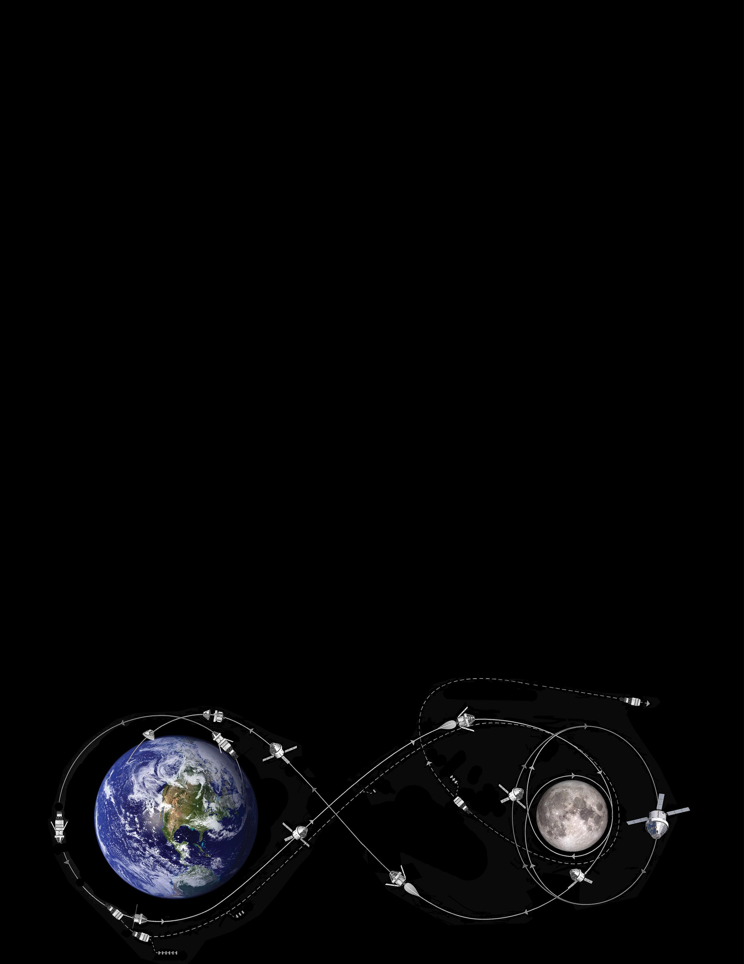
NASA ST7/ESA LISA Pathfinder
NASA is planning missions that will operate high-performance optical payloads with highly vibration-sensitive scientific instruments for science observations. Stringent pointing stability requirements to mitigate jitter and microvibration are key for such large space telescope missions of the future. Managing jitter is essential to obtain distortion-free images of planetary bodies on exo-planet coronagraph missions. Traditionally these space observatories have relied upon reaction wheels to provide the attitude-control torques needed for stabilization and pointing. For example, the Hubble Space Telescope (HST) uses four reaction wheels as part of its pointing control system. However, the reaction wheels themselves are typically the largest pointing disturbance source on the spacecraft, primarily due to static and dynamic mass imbalances in the flywheel as well as wheel-bearing mechanical noise. Therefore satisfying stringent jitter requirements for missions, in this class requires methods to limit or isolate vibrations generated by the wheels. On most high-performance observatory missions GNC engineers typically invest significant time and resources to conduct special reaction wheel disturbance characterization tests, exquisite wheel balancing, and the design and development of wheel-disturbance mechanical isolation devices.
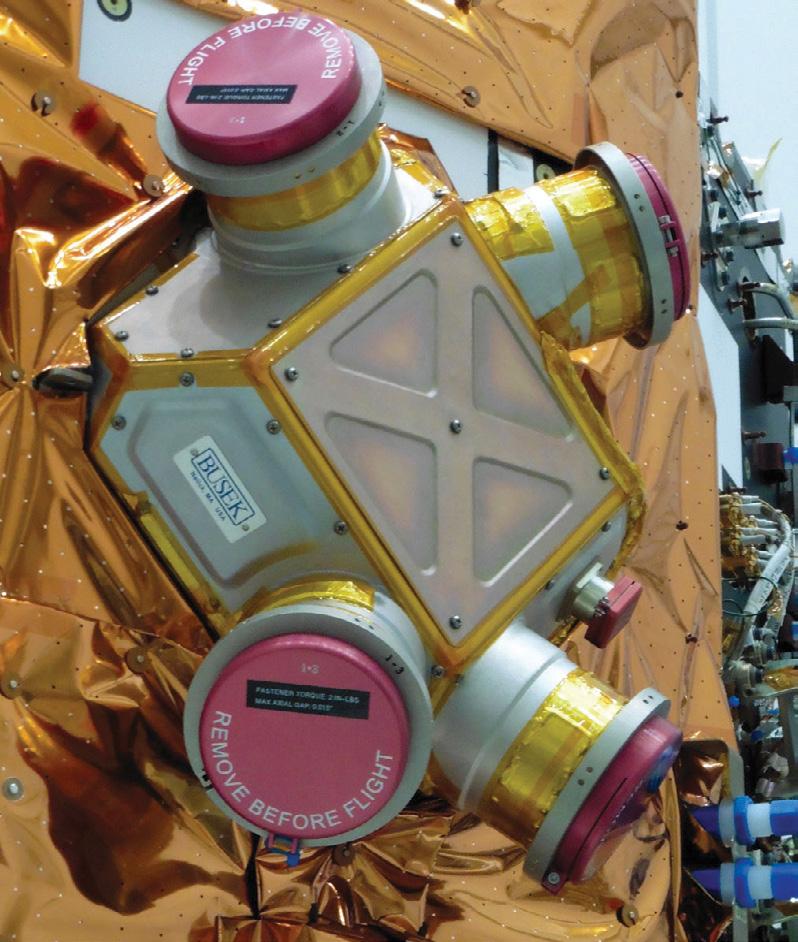
A recent NESC assessment investigated the feasibility of using microthrusters as an alternative or supplement to reaction wheels for providing attitude control during periods of scientific data collection requiring precision pointing. Microthrusters, or micronewton thrusters, are thrusters capable of producing forces in the micronewton range. Microthrusters have been developed by NASA as part of a drag-free control system for the Laser Interferometer Space Antenna (LISA) mission. Microthrusters come in different forms, using different types of propellant. The NESC assessment focused on cold-gas microthrusters that use gaseous nitrogen and on colloidal microthrusters, a type of electrospray thruster that applies a high electric potential difference to charged liquid at the end of a hollow needle in such a way that a stream of tiny, charged droplets is emitted generating thrust. Both cold-gas and colloidal microthrusters were flown on the NASA ST7/ESA LISA Pathfinder technology demonstration mission.
The assessment team recognized that the need for the observatory to perform large angle slew maneuvers would exceed the control authority of microthrusters, necessitating the use of either wheels or traditional reaction control system (RCS) thrusters (using hydrazine or bipropellants) for large slews. The need for different control actuators for large slews and fine-pointing leads to different mission operational scenarios studied by the team. One scenario used reaction wheels for performing large slews, which are then spun down to zero speed during science observations, with microthrusters used as the sole actuator for fine pointing. In this scenario, any need to mechanically isolate the reaction wheels is eliminated because the wheels are shut down during fine pointing. A second scenario employed RCS thrusters for large slews, with microthrusters used as the sole actuator for fine pointing. Both the cold gas and colloid microthrusters with their nanonewton resolution provide an appropriate level of attitude control torque to maintain the observatory’s fine pointing without introducing undesirable jitter. The assessment results indicated the microthrusters could provide an order of magnitude performance improvement relative to HST. The general conclusion is that microthrusters have potential for reducing the cost and technical risks of achieving demanding pointing stability performance on observatory-class missions. For more information, contact Cornelius J. Dennehy, cornelius.j.dennehy@nasa.gov or Aron Wolf, aron.a.wolf@jpl.nasa.gov.
One goal of the recent NESC assessment, Transient Combustion Modeling for Hypergolic Engines, was to identify and characterize the early reactions that occur between monomethylhydrazine (MMH) fuel and dinitrogen tetroxide (NTO) oxidizer in the liquid and gas phases to improve modeling for liquid-fueled space propulsion system hypergolic propellant engines. Drs. Tim Pourpoint and Hilkka Kenttämaa of Purdue University were asked to perform experiments to support the effort.
Identification of Reaction Products
Identifying the first products formed upon interactions of NTO and MMH requires an analytical technique capable of quickly and unambiguously providing elemental composition and structural information for the products. A combination of low- and high-resolution tandem mass spectrometry was chosen for this task. This technique requires the products to be converted into gas-phase ions before analysis. The initial products formed upon liquid- and gas-phase hypergolic reactions may react immediately with other liquids or gases that form in the mixture. Because the reactions cannot be halted to collect the first species generated, evaporation and ionization (if necessary) must occur at the moment the products form to ensure that the correct species are being analyzed. Based on this condition, the team selected laser desorption/ionization (LDI) as the most promising technique due to its speed. The current state of laser technology enables laser pulse lengths on the order of nanoseconds, much shorter than the expected time scale of the reactions of interest. LDI has been successfully used by researchers with a 355 nm laser to evaporate and ionize solid aromatic compounds1 , proteins2,3, and polymers4. Since MMH and NTO are relatively small molecules, have different structures compared to the types of samples discussed in the literature, and have largely unknown early reaction products, the energy of the photons and the laser power (density of photons) required for LDI of their products were unknown.
Purdue Test Facility
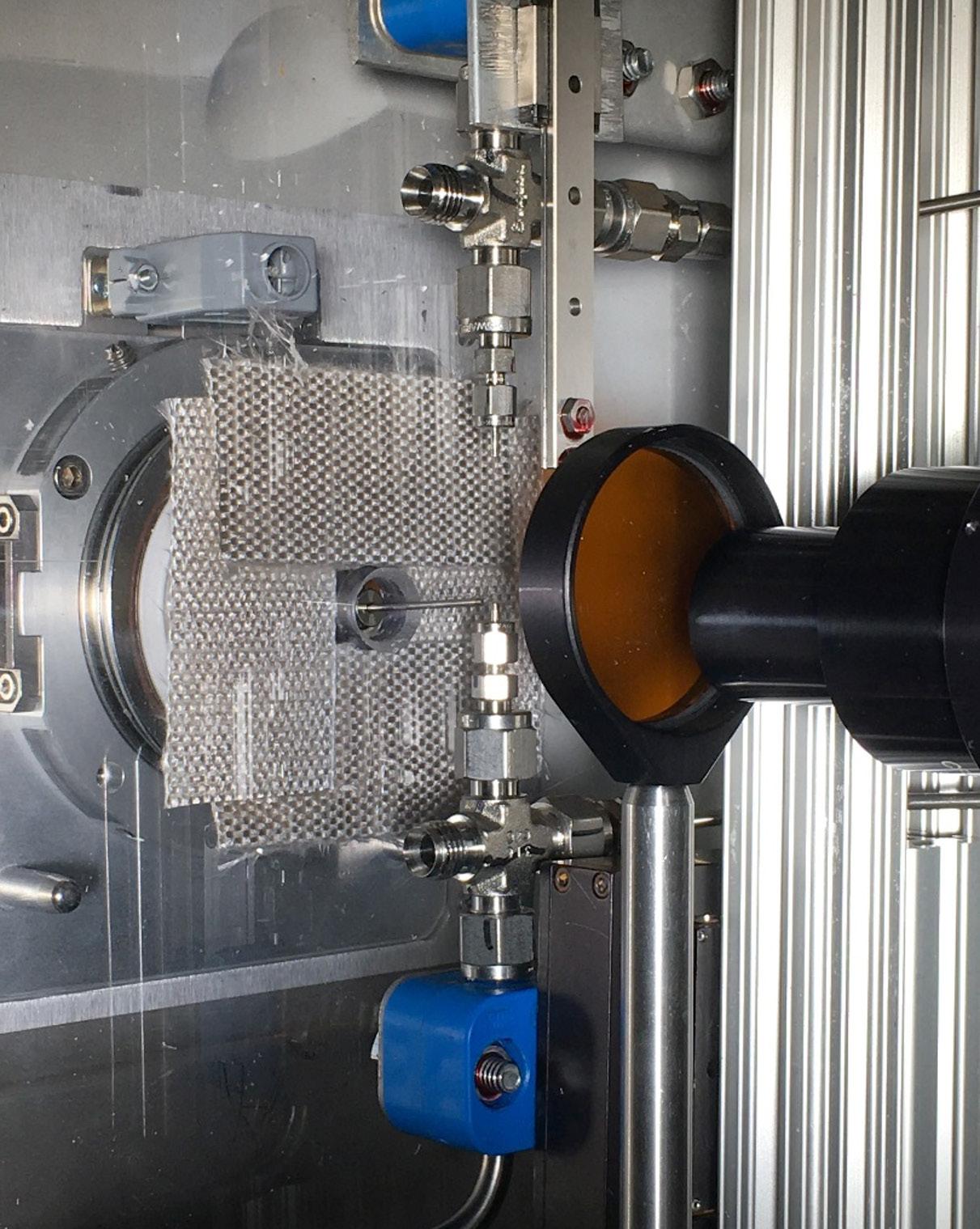
To conduct the investigation of the liquid phase and early gas phase reactions of MMH with NTO, the Purdue team designed an apparatus that brought approximately 3 μl drops of MMH and NTO into contact with each other in a highly repeatable manner, synchronized with the LDI technique, and under controlled conditions. The small liquid volumes made the experiment easier to control and improved safety. Figure 1 shows the final dropon-drop experimental apparatus installed in a mobile fume hood. The NTO drop was placed into the bottom tube as opposed to MMH due to its low surface tension. The MMH drop was then moved down to touch the NTO drop by using an actuator with a maximum actuation speed of 14 inch/second and spatial resolution of 1 μm. This high actuator speed was chosen to minimize interactions between NTO and MMH vapors before the drops contacted one another.
Dr. Daniel J. Dorney NASA Technical Fellow
for Propulsion
MMH/NTO Drop-on-Drop Testing
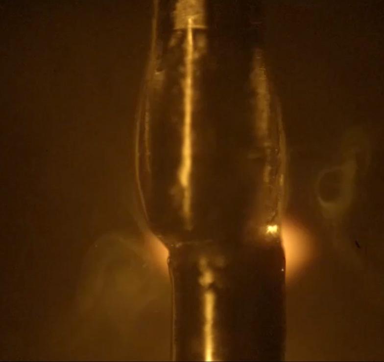
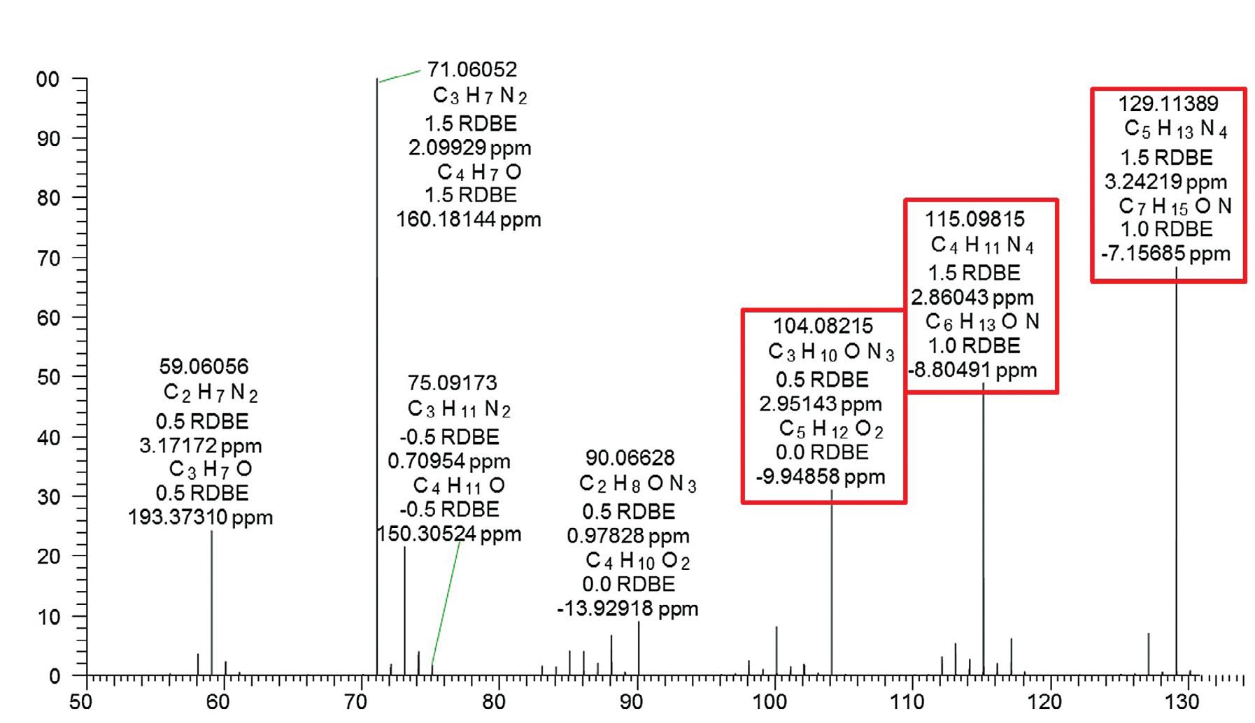
Prior to each experiment, the laser was allowed to warm up while the laser beam was blocked from entering the test area by a beam shutter. With the laser ready, the MMH drop was brought down and into contact with the NTO drop. Simultaneously, the data acquisition system sent a signal to the mass spectrometer to begin data acquisition. Shortly after triggering the mass spectrometer, the system sent a signal to open the beam shutter and allow a single laser pulse to pass next to the reaction just as the mass spectrometer began detecting ions. Figure 2 shows a still photo of the laser pulse hitting the area between the touching droplets and the mass spectrometer inlet during a test sequence. Evidence of the laser pulse is clearly visible because of the ionized gases created as the laser beam passes through the area. The orange coloration was caused by the laser filter used to protect the camera. Figure 3 shows a high-resolution mass spectrum measured for the MMH/NTO liquid reaction products showing the measured elemental compositions of the ions and proposed structures for some of the ions. Additional results demonstrated that the liquid-phase reactions of MMH and NTO readily produce large amounts of ions in the absence of any ionization method (i.e., LDI), which can be detected by the mass spectrometer. Aside from the ionic compounds produced, the neutral intermediates cannot be detected without LDI, which will be part of future experimentation.
Interestingly, while many positively charged ions were observed, only a few negatively charged ions, the most abundant corresponding to nitrate, were detected. These conclusions are in agreement with the nature of the highly energetic hypergolic reactions, as ions are much more reactive than neutral molecules in the gas phase. The results of the experiments conducted by the NESC assessment team will augment modeling capabilities with the objective of improving combustion instability predictions for existing and future hypergolic propellant engines. For more information, contact Dr. Daniel J. Dorney, daniel.j.dorney@nasa.gov.
References:
1.
2.
3.
4. Dotter, R. N.; Smith, C. H.; Young, M. K.; Kelly, P. B.; Jones, A. D.; McCauley, E. M.; Chang, D. P. Y. Laser Desorption/ Ionization Time-of-Flight Mass Spectrometry of Nitrated Polycyclic Aromatic Hydrocarbons. Anal. Chem. 1996, 68 (14), 2319–2324. https://doi.org/10.1021/ac951132r Kawasaki, H.; Akira, T.; Watanabe, T.; Nozaki, K.; Yonezawa, T.; Arakawa, R. Sulfonate Group-Modified FePtCu Nanoparticles as a Selective Probe for LDI-MS Analysis of Oligopeptides from a Peptide Mixture and Human Serum Proteins. Anal Bioanal Chem 2009, 395 (5), 1423. https://doi.org/10.1007/s00216-009-3122-0 Karas, M.; Ingendoh, A.; Bahr, U.; Hillenkamp, F. Ultraviolet–Laser Desorption/Ionization Mass Spectrometry of Femtomolar Amounts of Large Proteins. Biomedical & Environmental Mass Spectrometry 1989, 18 (9), 841–843. https://doi.org/10.1002/bms.1200180931 Gołda-Cępa, M.; Aminlashgari, N.; Hakkarainen, M.; Engvall, K.; Kotarba, A. LDI-MS Examination of Oxygen Plasma Modified Polymer for Designing Tailored Implant Biointerfaces. RSC Adv. 2014, 4 (50), 26240–26243. https://doi.org/10.1039/C4RA02656J
Ionization from laser pulse
Left: FIGURE 1 MMH/NTO drop-on-drop experimental configuration.
Above: FIGURE 2 Laser pulse hitting the MMH/NTO droplets.
Below: FIGURE 3 Example high-resolution mass spectrum collected during MMH/NTO drop-on-drop test. Ions boxed in red were subjected to Collision-Activated Dissociation in tandem mass spectrometry experiments to obtain structural information.
Jon B. Holladay
Systems Engineers Bring an NASA Technical Fellow for Systems Engineering Integrated Perspective to NASA Missions
Engineers from every technical discipline provide the critical subsystems necessary for NASA’s spaceflight missions. But ensuring these integrated subsystems will operate seamlessly at lift-off and successfully transport their payloads to their destinations requires the input of another technical discipline–systems engineering.
“The systems engineer is the jack-of-all-trades,” said Mr. Jon Holladay, NASA Technical Fellow for Systems Engineering (SE). He leads the 50-member SE Technical Discipline Team (TDT), which has found itself in high demand as NASA’s timeline for executing multiple, complex missions reaches an apex this decade. “To me, this is a revolutionary time at NASA,” Holladay said, ticking off a long list of anticipated near-term launches including the James Webb Space Telescope, Artemis I, the Habitation and Logistics Outpost, and Human Lander System.
“The ability to effectively integrate how we do what we do, in perhaps one of the most critical and complex arenas, is what systems engineering brings to the table,” he said. Increasing complexity and requirements for more autonomous operations and seamless data flow come with each new mission, all of which are maturing at speeds much faster than the decades-long development of earlier NASA programs like Apollo, Space Shuttle, and International Space Station (ISS). “We have to do more, move faster, and make decisions more quickly, and that requires understanding the integrated perspective of what those decisions mean.”
Mr. Holladay, his TDT Deputy Mr. Robert Beil, and TDT members have worked to establish the SE discipline as a vital Agency resource and communicate the importance of balancing technical issues with integration. The TDT’s statistics, data mining, systems analysis, and SE subject matter experts serve on standing review boards, mishap investigation teams, integrated hazard reviews, and technical standards evaluations. Pulling in subject matter experts from other technical disciplines, they also form assessment teams to help programs find the best strategies for integration and uncover the errors that, in complex systems, often trace back to where interfaces occur.
In 2020, the SE TDT led or participated in a range of activities that reveal the increasing importance of the integration aspect of systems engineering to NASA missions. They recently led a comprehensive review of SE, software, and systems integration lessons learned, the results from which are being leveraged for Artemis I and commercial flights to ISS. They are currently working with the thermal, power, and avionics disciplines on extravehicular activity power systems for ISS and lunar systems, opening the door to cross-program integration opportunities by exploring a common system architecture that could be used across multiple missions. And the TDT statistical team helped analyze whether a test program for a critical piece of propulsion hardware was robust enough to ensure reliability, which is growing in importance as NASA integrates with commercial partners striving for increased production rates and quick mission turn arounds.
The TDT also helped identify critical failure modes of ventilators for COVID-19 patients and consultation on verification and test methodology for non-NASA commercial vehicles.
In the coming decade, the SE TDT will continue integrating the pieces of the increasingly complex systems required to accomplish NASA’s future missions, leveraging what they learn from each assessment, conducting outreach through workshops and their community of practice, and taking advantage of digital platforms like model-based systems engineering.
“Often, if you are embedded in one project or program, you don’t always see that big picture,” Mr. Holladay said, noting the challenge for the SE TDT will be to bring those lessons learned and the big picture, integration perspective to every NASA mission. For more information, contact Jon B. Holladay, jon.holladay@nasa.gov.
Dr. Cynthia H. Null NASA Technical Fellow for Human Factors
Defining Human Error Analysis for Human Rating of Crewed Spacecraft
NASA’s Human-Rating Requirements for Space Systems (NPR 8705.2C) calls for Program Managers to conduct a human error analysis (HEA) during system development. The analysis should cover all mission phases, including ground processing, launch preparation, flight, and recovery/disposal operations. The purpose is to identify human errors that could lead to catastrophic outcomes and apply this information to identify areas for design changes. The requirement makes it clear that HEA is a qualitative analysis that complements probabilistic hazard assessments. The requirement for HEA applies to systems developed by NASA, but depending upon agreements, HEA may also be applied to other crewed space systems.
For as long as the NASA HEA requirement has been in force, there has been uncertainty about exactly what is a human error analysis, and how should one be done. In 2018, after the NESC received a request for guidance on this issue, Dr. John O’Hara (Brookhaven National Lab) and Dr. Alan Hobbs (San Jose State University) were tasked with answering these questions. The resulting position paper Guidance for Human Error Analysis was approved by the NESC Review Board in November 2019 and is available as NASA/ TM-2020-5001486.
Their resulting position paper presents methods that can be used to meet the intent of NPR 8705.2C, but does not rule out the use of alternative approaches. The document covers the essential elements of human error analysis including establishing the HEA team; screening-in tasks for analysis; identifying potential catastrophic errors for each analyzed task; error management strategies; and documenting the analysis.
Error analysis is about identifying and mitigating problems at a system level, and not about finding fault with individuals. In many cases, errors occur in the context of error-producing conditions in hardware, software, or procedures. If we can influence the design to eliminate these conditions, we can reduce the likelihood of human error, while retaining the positive contribution that humans make to system operations.
The position paper distinguishes error-producing conditions (EPC) from error traps. An EPC is a general condition (such as time pressure or fatigue) that can increase the likelihood of error across a range of tasks. An error trap is a particular set of circumstances that can provoke a specific error, e.g., adjacent items of hardware with compatible connectors that enable a cross-connection error. Many EPCs can never be eliminated entirely. However, in most cases, error traps can be designed out of the system. The elimination of error traps is one of the most valuable outcomes of HEA. For more information, contact Dr. Cynthia H. Null, cynthia.h.null@nasa. gov or Dr. Alan Hobbs, alan.hobbs@nasa.gov.
General HEA Principles
The goal of HEA is to enhance system reliability and safety.
HEA is an iterative process.
HEA is directed at the entire system, not people alone.
HEA cannot be applied in detail to every task.
HEA must consider tasks in context.
HEA must consider work as actually performed.
HEA should be integrated with other analyses.
HEA benefits from independent perspectives.
HEA should be performed by a multidisciplinary team.
HEA requires input from operational personnel.
HEA requires imagination.
There is no single correct approach to HEA. HEA enhances system reliability and safety by identifying where significant human errors could occur, the conditions that could provoke these errors (including error traps), and means to mitigate them.
Analysis of potential human errors should occur throughout all phases of the design process.
HEA identifies problems with the total system, including hardware, software, equipment, facilities, processes, and procedures. HEA is not about finding fault with people or attributing blame.