
5 minute read
February 2024 Hybrid & Electric Vehicle Corner


By Curt Ward, Professor at Joliet Junior College
Exploring the 5th Generation Toyota Hybrid Synergy Drive
As I write this article, snow is falling in Chicagoland, and the spring semester is off to a fast-paced start. Recently, I had the opportunity to tear down the hybrid transmission out of a 2023 Toyota Corolla Hybrid. The model I disassembled was a PA10, which is used behind the 1.8- and 2.0-liter 2ZR hybrid engines. In this article I will highlight some of the differences between this transmission and a second-generation transmission I shared with you at the summer conference in Northern Kentucky.
My objective in disassembling the transmission was to create a power flow demonstrator, which will become part of a hands-on lab activity in our hybrid and electric vehicle program. Students will be able to demonstrate power flow, calculate gear ratios, measure winding resistance, and test for a loss of isolation.
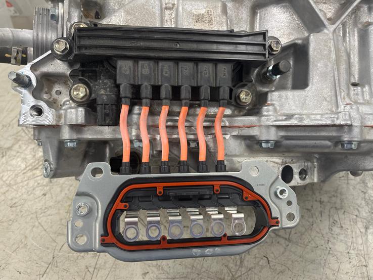
The first item I noticed was the size of the cables that are between the transmission motor windings and the inverter (See Figure 1). Compared to earlier designs, these cables are much smaller. This change occurred because the system voltage is lower, the motorgenerator power ratings are lower, and the inverter is located directly on top of the transmission.
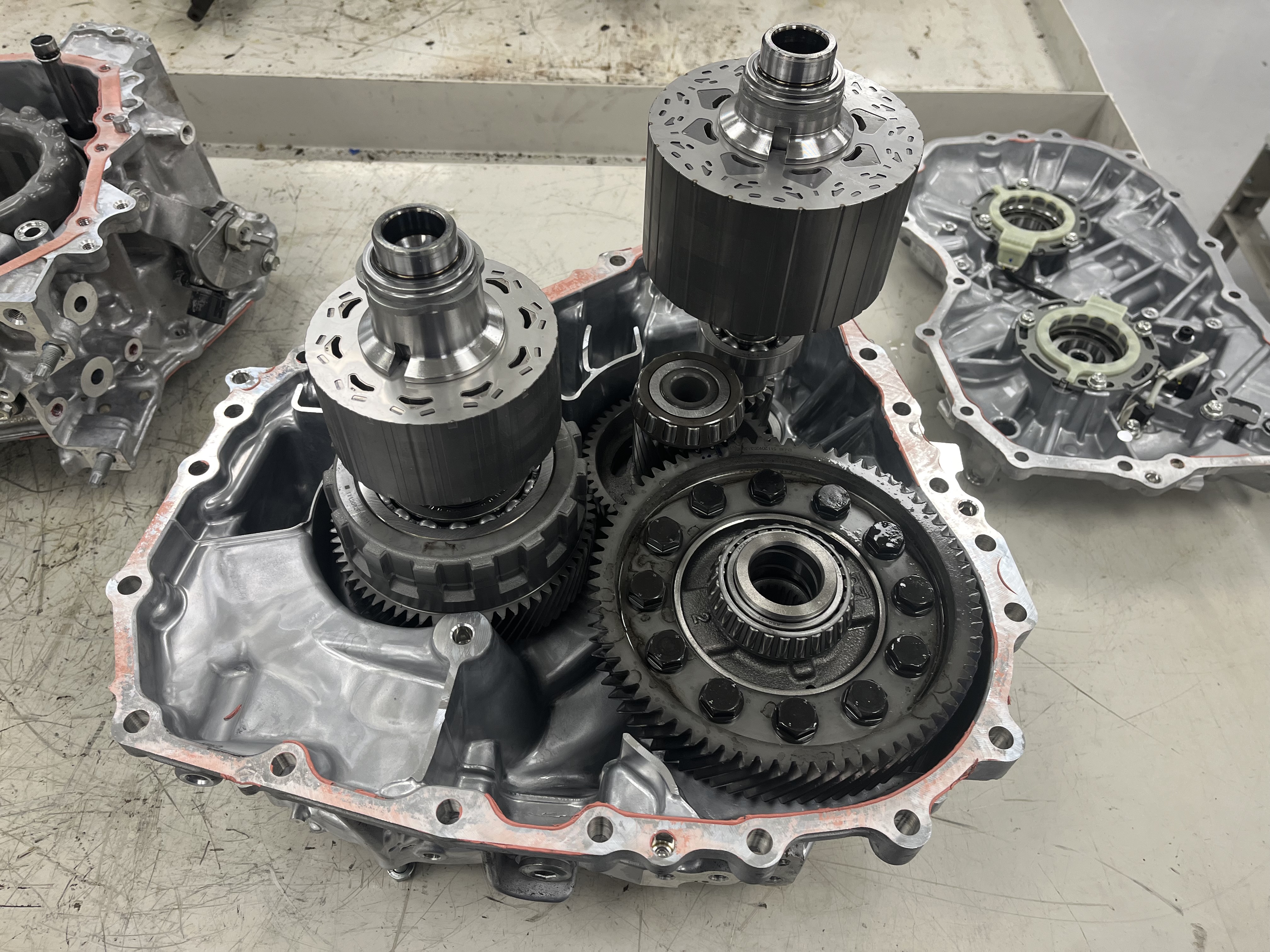
During the disassembly, an item that caught my attention was the similarities of this 5th generation transmission to the 4th generation P610 series transmission. The P610 (as well as the P710 and P810) were the first of the Toyota hybrid transmissions to use a parallel power flow design. The previous generations of the transmission used a series power flow design. The PA10 uses a parallel power flow design (See Figure 2). As in all previous generations, motor generator 1 (MG1) is still used to start the internal combustion engine and to charge the high-voltage battery. Motor-generator 2 (MG2) is used to propel the vehicle. In the parallel power flow design the internal combustion engine, in combination with MG1 through the power-split device, can provide additional torque to MG2 to help move the vehicle. Both motor-generators are smaller than earlier series power flow designs. MG1 is rated at 23Kw and MG2 is rated at 53Kw. The additional needed torque is created by changes in gear ratios in the final drive assembly.
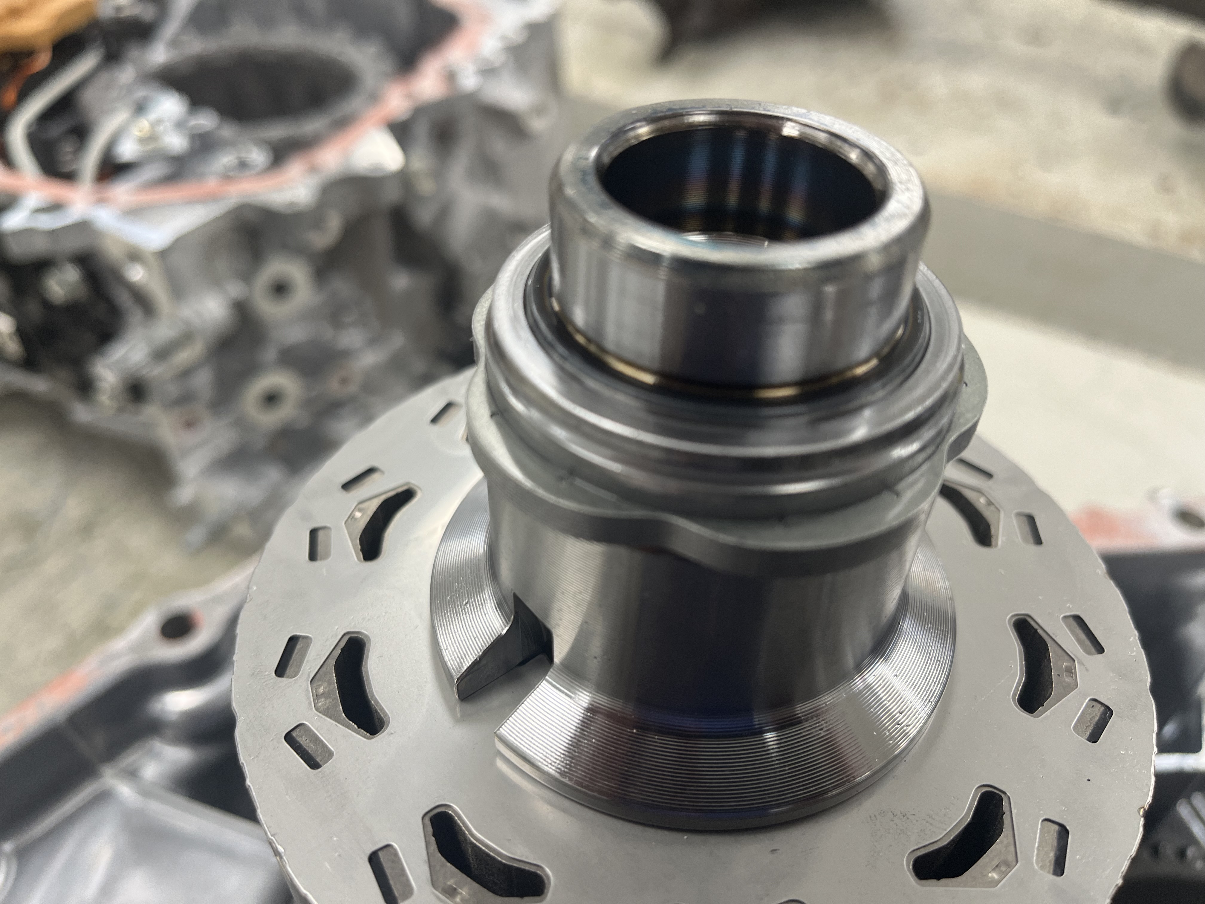
The MG1 and MG2 resolvers are different from previous models. Resolvers are used on systems with permanent magnet motors to determine motor position, speed, and direction of rotation. The resolvers for MG1 and MG2 appear to be electrically the same, however, they have different part numbers, and they are not interchangeable due to the way they are indexed. The trigger mechanism for the resolver for MG1 appears to be a higher definition version than MG2 (See Figure 3). It has more detents, and therefore would create a more frequent signal change.
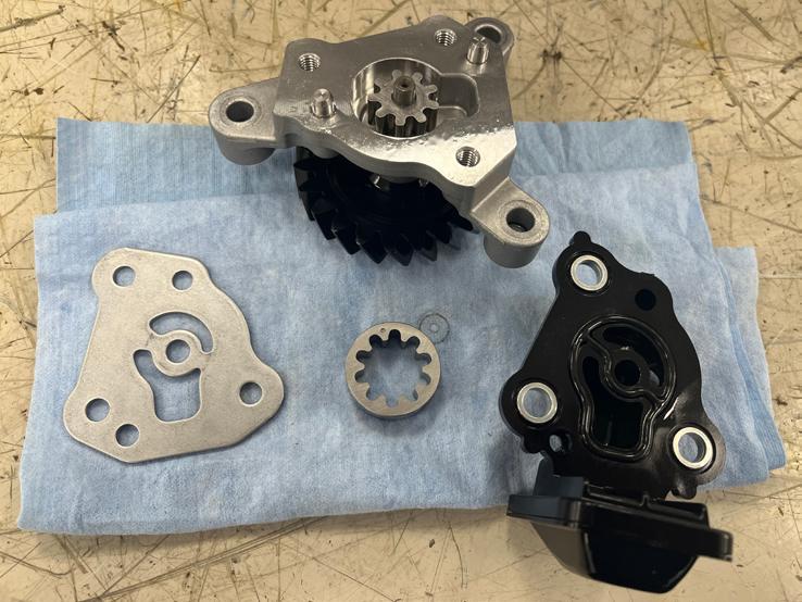
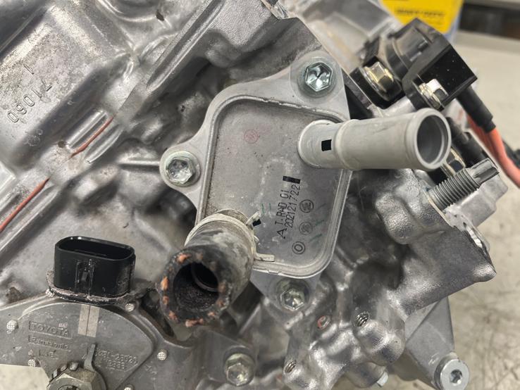
Another significant change in the parallel power flow design is the way the transmission is lubricated and cooled. The oil pump is now an internal component. In the series power flow design, the oil pump was external. The design of the oil pump is different from the 4th generation transmission, which was also an internal pump. Additionally, the displacement of the pump has been increased (See Figure 4). The increased volume of lubricant will result in better heat absorption. The oil pump is turned by the internal combustion engine via the planetary gear set. This means the oil pump only operates when the internal combustion engine is turning. The “Prime” version of the transmission has an external electric oil pump that operates anytime the vehicle is in electric mode. The oil cooler, that was internal on the series design transmission, is mounted externally on the parallel design (See Figure 5). It seals to the transmission case with two O-rings. Coolant is circulated through the transmission, the inverter, and the radiator by an electric coolant pump.
The items described in this article are just a few of the differences and highlights of this transmission when compared to previous models. For a complete overview of the 5th generation Toyota hybrid synergy drive, look for my presentation during the upcoming conference season.
I will finish this article with the same offer I make after each of my presentations. If you are interested in getting started in the process of adding hybrid and electric vehicles to your curricuulum or want more information, please feel free to reach out. I am more than willing to sit down in-person or online and share my experiences. Are you looking for a classroom textbook? Reach out to Pearson and ask for a review copy of the all-new Electric and Hybrid Electric Vehicle text that Jim Halderman and I co-authored. It is a comprehensive text covering all the latest information on the subject.