
5 minute read
February 2023 Hybrid & Electric Vehicle Corner


By Curt Ward, Professor at Joliet Junior College
What about Megohm Meters and Milliohm Meters?
As I share the possibilities of adding hybrid and electric vehicles to the curriculum with automotive instructors and administrators around the country, I get many questions on the subject of megohm meters and milliohm meters. These are not tools that are typically part of a standard automotive program inventory, however, as a program moves towards electrification, they will become as common as a 10mm socket. In this article I will highlight the use of these meters and specific vehicle or component testing. The goal of the testing is not to resolve a specific problem, but rather to demonstrate and better understand the operation of the meters.
I want to begin with the megohm meter. Its principal use is to measure resistance using a source voltage greater than the typical 9-volt battery found in a multimeter. On the hybrid and electric vehicle, it is used to identify problems related to a “loss of isolation” in the high-voltage circuits.
Caution: It is important that proper personal protective equipment be worn when using a megohm meter to test high-voltage circuits.
Most megohm meters are also able to perform the same functions of a typical multimeter. When making a megohm meter purchase decision, look for a meter that has a minimum CAT III 1000-volt rating. This will meet or exceed the requirements for every hybrid and electric vehicle currently in production. Do not modify the meter leads in any way, as this will nullify the minimum CAT III rating.
A “loss of isolation” fault typically sets when the control module detects a possible path to the chassis ground from either the positive or negative high-voltage circuit. As part of the diagnostic process, many manufacturers will have the technician place the megohm meter between the suspect circuit or component and chassis ground and check for continuity. Because a high-voltage circuit can jump to ground (arc-flash) through the air, the circuit is tested with a high source voltage. Most megohm meters have an internal capacitor that is charged to the specified voltage by the source battery and then discharged during the test. When performing the test, the one-hand method is recommended. (See Figure 1 – Megohm Meter)
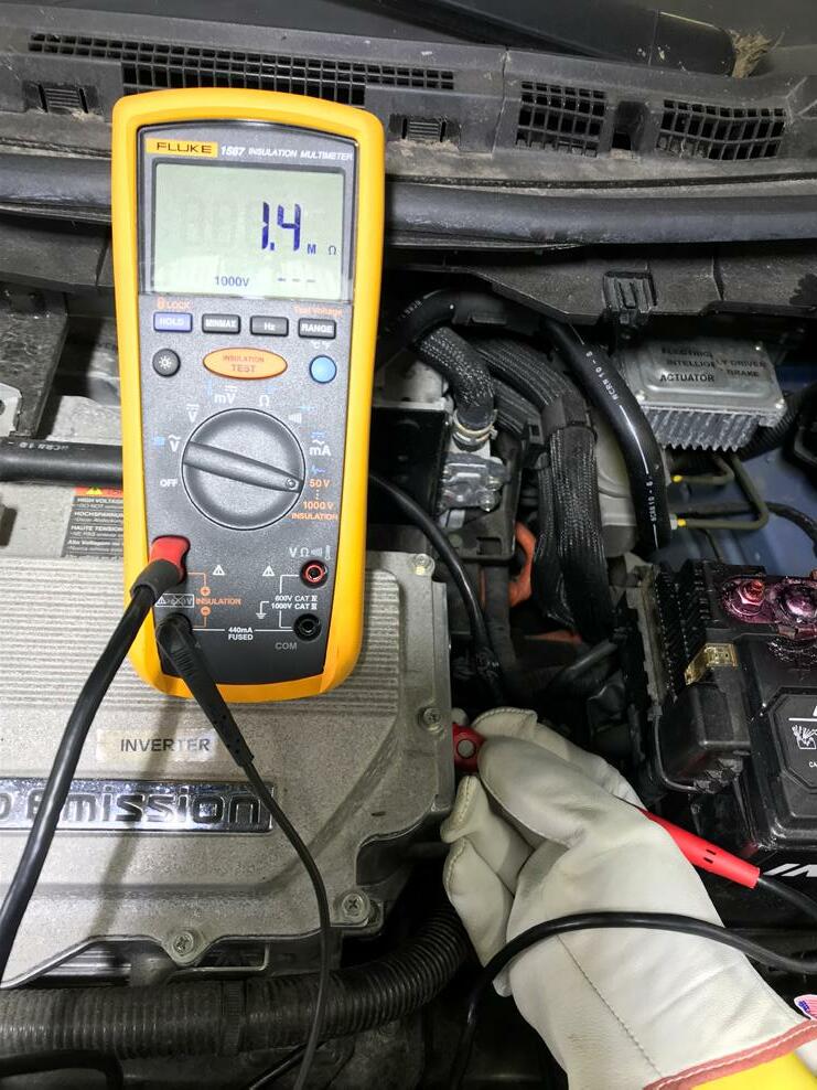
Figure 1: Megohm Meter
An easy way to safely demonstrate the meter use with a group of students is first connect the meter between the chassis ground and something that is insulated (plastic or other non-conductive material). When the test is performed, the meter will indicate an almost infinite resistance. For the second part of the demonstration, move the meter lead to a conductive part of the chassis and perform the test a second time. The results will indicate little to no resistance.
The milliohm meter is used to test circuits where the normal resistance is less than one ohm. Despite what is advertised, the typical multimeter is not accurate below one-ohm of resistance. When measuring most legacy vehicle circuits this is not a concern because the specifications for the circuit resistance is not less than one-ohm. However, if a measurement is being made on the stator windings of an electric motor in a hybrid or electric vehicle the specification will most likely be a very small range of milliohms. (See Figure 2 – Milliohm Meter)
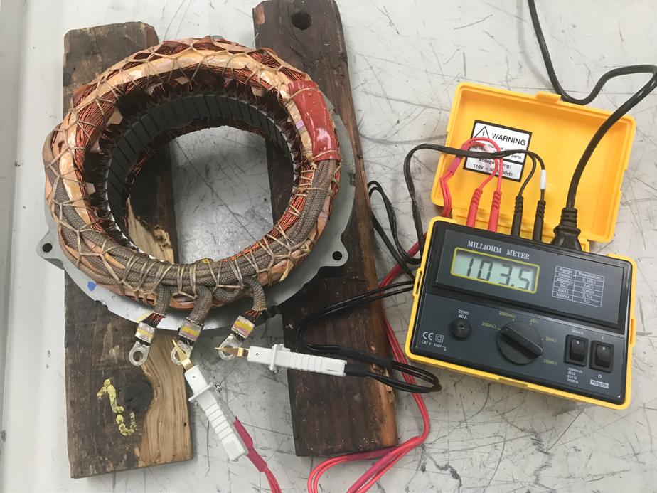
Figure 2: Milliohm Meter
A milliohm meter may be battery powered, or it may have a 120 Volt AC power cord. The milliohm meter uses test leads with Kelvin clips and requires a calibration each time before use. Some measurements are so precise the meter and the components must be verified to be at room temperature before the measurement is made.
A fun way to demonstrate a milliohm meter is to use three pieces of standard 14-gauge stranded automotive wire; one 20-inches long, one 10-inches long, and one 1-inch long. First, measure each wire with a standard multimeter. Each wire, despite the difference in length, will measure the same. Second, measure each wire with the milliohm meter. Each wire will have a different resistance. For the last part of the demonstration, use the 20-inch wire and fold about one-half of the strands at each end out of the way (where they are not touching) and remeasure. The reading will be different than the previous reading of the same wire. What a great demonstration of a poor or damaged harness or connector!
Neither of these tools is currently part of the standard workshop toolbox, and I only bring them out for the hybrid and electric class or to spice up the Electrical I class discussion on resistance. Even if you are not ready to add hybrid and electric vehicles to your curriculum, these tools are a great way to introduce the topic of high-voltage safety and to increase the learning on the topic of resistance.
I will finish this article with the same offer I make after each of my presentations. If you are interested in getting started and want more information, please feel free to reach out. I am more than willing to sit down in-person or online and share my experiences. Are you looking for a classroom textbook? Reach out to Pearson and ask for a review copy of the all-new Electric and Hybrid Electric Vehicle text that Jim Halderman and I co-authored. It is a comprehensive text covering all the latest information on the subject.

