FlexmasterJoints ConveyingProducts


This is part of our brand name library available at: www.HoseWarehouse.com/catalogs Warehouse HOSE Authorized Wholesale Distributor Bulk Pricing Trained Techs & Customer Supoort Quick Order Fulfillment Product Warranty Product Traceability Recall notification
Page 1
Flexmaster Joints in Standard and Self-restrained Configurations
Standard Features
1.Gasket provides compression seal when tightened against tube or pipe.
2. Hinged coupling provides for quick, easy assembly.
3.Bulged sleeve allows for ±4º angular misalignment. All gasket materials listed on page 4 are available in the st andard style, increasing the number of suitable applications.
Self-Restrained Features
1.Gasket provides compression seal when tightened against tube or pipe.
2. Hinged coupling provides for quick, easy assembly.

3.Bulged sleeve allows for ±4º angular misalignment.
4. Notched channel ring which grips pipe firmly to restrict movement along pipe or tubing. Gasket materials available include the C (Buna-N) and D (EPDM) compounds.
Flexmaster joints are available in both standard and selfrestrained styles. The self-restrained style has a stainless steel gripping ring inside each gasket. This feature allows the joint to maintain a firm grip on the pipe or tube, preventing movement along the pipe or tube.
The bulged, straight-through Flexmaster joints accommodate angular misalignment up to ±4º per end. Tees, elbows, and crosses accommodate angular misalignment up to ±2o per end. See pages 10 thru 17 for the angular misalignment allowed on each specific part. Flexmaster joints are designed for up to 300 psi (2.07 MPa) service, depending on application and size. Refer to pressure ratings on page 4.
Flexmaster joints absorb vibration and are ideal for making quick connections and disconnections when repairing or disassembling a system. They can be furnished with several types of gasket compounds and sleeve materials, including stainless steel for marine and corrosive applications.
Flexmaster joints are currently in use in thousands of applications throughout the world. For typical Flexmaster joint applications see photos on page 2.
EATON Hydraulics Flexmaster Joints Catalog E-MEFL-MR001-E2 January 2008 II
Features
Page 2
No threading, flanging, welding, grooving or other special end preparation of tube or pipe is required. Use pipe after it is cut to appropriate lengths. The Flexmaster joint will accommodate large tolerances in the length of the gap. See Table 1, page 9 for insertion depth tolerances.
Absorbs Vibration
Pipe vibration and noise can be drastically reduced with Flexmaster joints. The resilient, thick rubber of the Flexmaster joint gasket absorbs vibration and noise. Use of the self-restrained style restricts movement along vibrating pipes and tubes.
Even Misaligned Piping is No Problem
The Flexmaster joint design eliminates flanged bolt holes and pipe threads that require careful alignment. The Flexmaster bulged joint permits up to a total of ±4º angular installation misalignment at each end while maintaining a leakproof seal. Installation time can be slashed by using Flexmaster joints. Basic assembly tools are all that’s needed. After extensive use, the gaskets can be replaced easily and quickly. See page 8 for complete assembly instructions.

EATON Hydraulics Flexmaster Joints Catalog E-MEFL-MR001-E2 January 2008 � Used on Plain End Tube or Pipe Features Save TimeMake Pipe And Tube Connection Easier
Easy to Install
Page 3


EATON Hydraulics Flexmaster Joints Catalog E-MEFL-MR001-E2 January 2008 � Applications
Flexmaster joint elbows on a large hydraulic power system, which connect pipe from pumps to hydraulic fluid reservoirs.
Flexmaster joints join water lines on a huge diesel engine.
A number of Flexmaster joints are installed on this compressor to connect water and oil lines, providing quick, easy connection and protection against vibration.
A large dry-cleaning plant uses Flexmaster joints to connect piping at elbow junctures.
Page 4
Flexmaster joints are used to join piping on air compressors.
Specials Made to Order
Special
Configurations and Seal Materials Can Be Ordered
Flexmaster joints can be produced with various configurations and terminal end designs. A few of the special Flexmaster joint configurations which have been manufactured by Eaton are displayed above. Please consult Eaton when ordering specials.

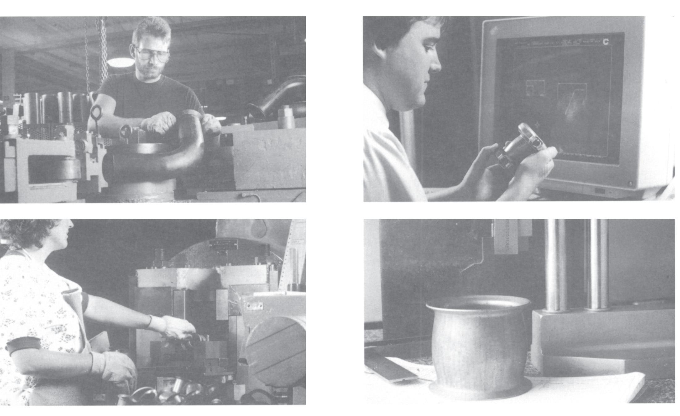
Manufacturing Engineering
EATON Hydraulics Flexmaster Joints Catalog E-MEFL-MR001-E2 January 2008 �
Flexmaster joints are manufactured by highly experienced and trained individuals who are dedicated solely to the production and packaging of Flexmaster joints.
The Flexmaster joints manufacturing team is backed by the strong technical support from Eaton’s engineering staff.
Page 5
º
GASkET TEMPErATUrE rATINGS††
C BUNA-N water -25º F. to +180º F. (Standard) (-32º C. to +82º C.)
oils -25º F. to +212º F. (-32º C. to +100º C.)
V -25º F. to +450º F. Fluorocarbon (-32º C. to +232º C.)
S -65º F. to +350º F. Silicone (-54º C. to +177º C.)
D water and +20º F. to +275º F.
EPDM water/glycol (+29º C. to +137º C.) mixture
N BUNA-N water and -25º F. to +225º F. (High temp.) steam (-32º C. to +107º C.)
oils -25º F. to +250º F. (-32º C. to +121º C.)
†† Maximum temperature ratings are meant as a guide only. For extreme temperature conditions, consult factory. VAcUUM rATINGS
† Warning: The Flexmaster joint is designed to seal pipe and tube connections. The Flexmaster joint is not intended to hold piping systems together. Normal hangers, guides, anchors and other external piping restraints must be used to restrain the piping or tubing system from movement.
PIPE ANd TUbE MATErIAlS whIch cAN bE cONNEcTEd by FlExMASTEr jOINTS*
EATON GASkET INdENTIFIEr chArT
Gasket Gasket Gasket Identifying Designation Compound Color Color Patch
C Buna N (std) Black Yellow or White
N Buna N (high temp) Black Rust Orange
D EPDM Black Dark Blue
V Fluorocarbon Black Light Green
S Silicone Rust Orange None
* All piping and tubing connected by Flexmaster joints must meet the nominal O.D. dimensions presented on pages 10 - 17.
** Piping and Tubing, which use self-restrained gaskets, must have a hardness between 45-85 on a Rockwell “B” scale (45 - 85 Rb).
EATON Hydraulics Flexmaster Joints Catalog E-MEFL-MR001-E2 January 2008 �
Size Range Standard Self-Restrained Pipe Tube Gasket Gasket All sizes All sizes �5 in. Hg. �5 in. Hg. 1.79 bar 1.79 bar
†
NOTE:
F., inches, in. Hg., psi in bold
C., mm, bar, MPa in light
º
Size Range Standard Self-Restrained Pipe Tube Gasket Gasket 3/8 - 3/4 1/2 - 1 3/8 300 psi 300 psi 12.7 - 35.1 (2.07 MPa) (2.07 MPa) 1-2 1 1/2 - 2 1/2 200 psi 200 psi 38.1 - 63.5 (1.38 MPa) (1.38 MPa) 2 1/2 - 6 3 - 6 150 psi 150 psi 76.2 - 152.4 (1.03 MPa) (1.03 MPa)
PrESSUrE rATINGS †
Pipe or Tube Standard Self-Restrained Material Gasket Gasket** Carbon Steel X X Stainless Steel X X Aluminum X Not Recommended P.V.C. (Plastic) X Not Recommended Copper X Not Recommended
Technical data
Page 6
Technical data
Gasket Selector Chart
Gasket Material: C – BUNA-N (standard)
D – EPDM
N – BUNA-N (high temperature)
V – Fluorocarbon S
Key: G – GOOD
F – FAIR
– Not Recommended
An important consideration in the selection of a gasket material is to avoid undesirable chemical reaction between the agent carried and the gasket material. The gasket selector chart indicates the compound most serviceable in specific agents.
EATON Hydraulics Flexmaster Joints Catalog E-MEFL-MR001-E2 January 2008 5 FlUId GASkET MATErIAl D C/N V S Acetic Acid (concentrated) RT F F G F Acetic Acid (dilute) RT (to 10%) F F G G Acetic Acid Vapors F F F F Acedit Anhydride - F - F Acetone G - - F Acetylene G G G F Air G G G G Air (Hot) 215º G F G G Alcohols, Aliphatic G F G G Alcohols, Aromatic F - F F Alkaline Solutions (Hydroxides) F G F G Aluminum Salt solutions G G G G Ammonia Gas (Cold) G G -Ammonia, Liquid (Anhydrous) G G - F Ammonia Aqueous G F - G Ammonium Salt Solutions G G F F Aniline Dyes F - G F Aniline Oils F - F F Asphalt - - GBenzine (Gasoline) - G GBromine - - GButylene - F GCalcium Hypochlorite G - G F (no free Chlorine) Calcium Salt solutions G G G F Carbolic Acid (Phenol) RT or Hot F - GCarbon Dioxide (Dry) G G F F Carbonic Acid G F G G Carbon Disulphide RT - - GCarbon Tetrachloride RT - - GChlorinated Solvents - - G G Chlorine (Dry) - - GChlorine (wet or solutions) F - GCottonseed Oil G G G G Creosote (wood or coal tar) - G GChromic Acid 50% - F GCitric Acid G G G G Copper Salt Solutions G F G G Diesel Fuel - G GEthers RT F F GEthylene Glycol G G G G Ethylene Dichloride - - G G Ferric Salt Solutions G G G G Ferrous Salt Solutions G G G G Formaldehyde RT F - - G Fuel Oil - G FFurfural G - -Freon 12 (Refrigerant) G G GFreon 13 (Refrigerant) F G GGasoline (Sour or refined) - G GGlycerin (Glycerol) G G G G Heptane - G GHexane - G GFlUId GASkET MATErIAl D C/N V S Hydraulic Oils - G GStraight Petroleum Base Water Petroleum Emulsion - G G F Water Glycol G G G F Straight Phosphate Ester G - F F Phosphate Ester/Petroleum Blend - - FEster Blend G G F F Silicone Oils G G GHydrochloric Acid RT G F GHydrofluoric Acid (48% sol) RT - - GHydrolube G G G F Hydrogen Peroxide (dilute) F F G G Hydrogen Peroxide (concentrated) - - F F Hydrogen Sulfide (dry) RT F F -Hydrogen Sulfide (wet) RT F - GHypochlorite Solutions G F G F (no free Chlorine) Kerosene RT - G GLinseed Oil - G GLube Oil (Mineral) - G GLubricating Oils (Diester Base) - F GMagnesium Salt Solutions G G G G Mercuric Chloride G G GMercury G G G F Mineral Oil - G G G Naphtha - F GNapthalene - - GNitric Acid (less than 20%) F - GOleic Acid - G FOxalic Acid G F G F Oxygen, Gaseous G F G G Paraffin - G G F Petroleum Oils (Sour or Refined) - G GPhosphoric Acid (Commercial) G - GPotassium Salt Solutions G G G G Pydraul C Series, F F - G F Pydraul F Series G - -Sodium Salt solutions G G G F Steam F - -Sulfur G - -Sulfur Dioxide (wet or dry) G - - F Sulfuric Acid (10-75%) F - GSulfuric Acid (75-95%) - - GSulfuric Acid (95%)
- - GSulfurous Acid - F GTannic Acid F G F F Trichlorethylene - - GTurpentine - F GVegetable Oils G G G G Water (fresh or salt) cold G G G G Water (fresh or salt) hot G !! G+215º F. max. Xylene - - GZinc Salt Solutions G G G G !! C maximum +180º F., N maximum +225º F.
RT
– Silicone
Page 7
Standard (Un-restrained) Style
Self-restrained Style
Basic Part Number (from pages 10 - 17)
Example: NH��00
Gasket Material:
C = BUNA-N (standard)
D = EPDM
*N = BUNA-N (high temperature)
*S = Silicone
*V = Fluorocarbon
NH��XX ( ) 000 ( ) 000
Joint Length (in thousands of inch).
Example: 2.5” = 0250
Style is available in lengths shown. Other lengths are available in multiples of 1-inch on special requests. Contact Eaton for availability.
Sleeve Material:
B = Plated Steel (Standard)
S = Stainless Steel (Sleeve onlyconsult Eaton for availability)
* Available in Standard (Un-Restrained) Model Only.
Example Part Number: NH��00C075B0�50
Complete assemblies may be ordered by the procedure shown above. Standard components may be ordered as shown on page 7.
Size of Pipe or Tube to be connected (in hundredths of inch) Example: .75” = 075

EATON Hydraulics Flexmaster Joints Catalog E-MEFL-MR001-E2 January 2008 � how To Order
Page 8
Technical data
Parts List
EATON Hydraulics Flexmaster Joints Catalog E-MEFL-MR001-E2 January 2008 7 STrAIGhT GASkET cOUPlING SlEEVES rETAINEr GASkETS Tube Tube Includes Material Available Material Available size O.D. Nut & Bolt from Stock Self Restrained from Stock (inches) (inches) Standard Standard Standard Standard Gasket C D N S V Gasket C D* 1.00 1.00 NH100085-075YF NK1237-075B0250 NK1000023-075 NK1000064X100 X X X X X NK1000062X100 X X 1.25 1.25 NH100085-100YF NK1237-100B0288 NK1000023-100 NK1000064X125 X X X X X NK1000062X125 X X 1.38 1.38 NH100086-150YF NK1237-138B0300 NK1000056-138 NK1000064X138 X X X X1.50 1.50 NH100086-150YF NK1238-150B0300 NK1000056-150 NK1000064X150 X X X X X NK1000062X150 X X 1.75 1.75 NH100085-150YF NK1238-175B0350 NK1000056-175 NK1000064X175 X X X - - NK1000062X175 X X 2.00 2.00 NH100086-200YF NK1238-200B0350 NK1000056-200 NK1000064X200 X X X X X NK1000062X200 X X 2.25 2.25 NH100085-200YF NK1238-225B0400 NK1000056-225 NK1000064X225 X X X -2.50 2.50 NH100086-250YF NK1238-250B0400 NK1000056-250 NK1000064X250 X X X X X NK1000062X250 X X 2.88 2.88 NH100085-250YF NK1237-250B0650 NK1000023-250 NK1000063X250 X X X X X NK1000061X250 X X 3.00 3.00 NH100086-300YF NK1238-300B0500 NK1000056-300 NK1000064X300 X X X X X NK1000062X300 X X 3.25 3.25 NH100086-325YF NK1238-325B0650 NK1000056-325 NK1000064X325 X X X -3.50 3.50 NH100085-300YF NK1237-300B0650 NK1000023-300 NK1000063X300 X X X X X NK1000061X300 X X 4.00 4.00 NH100085-350YF NK1237-350B0650 NK1000023-350 NK1000063X350 X X X X X NK1000061X350 X X 4.50 4.50 NH100085-400YF NK1237-400B0650 NK1000023-400 NK1000063X400 X X X X X NK1000061X400 X X 5.00 5.00 NH100086-500YF NK1238-500B0650 NK1000056-500 NK1000064X500 X X X - - NK1000062X500 X X Pipe Pipe Size O.D. (inches) (inches) .38 .675 NH100085-038YF NK1237-038B0200 NK1000023-038 NK1000063X038 X X X -.50 .840 NH100085-050YF NK1237-050B0225 NK1000023-050 NK1000063X050 X X X X X NK1000061X050 X X .75 1.050 NH100085-075YF NK1237-075B0250 NK1000023-075 NK1000063X075 X X X X X NK1000061X075 X X 1.00 1.315 NH100085-100YF NK1237-100B0288 NK1000023-100 NK1000063X100 X X X X X NK1000061X100 X X 1.25 1.660 NH100085-125YF NK1237-125B0325 NK1000023-125 NK1000063X125 X X X X X NK1000061X125 X X 1.50 1.900 NH100085-150YF NK1237-150B0350 NK1000023-150 NK1000063X150 X X X X X NK1000061X150 X X 2.00 2.375 NH100085-200YF NK1237-200B0400 NK1000023-200 NK1000063X200 X X X X X NK1000061X200 X X 2.50 2.875 NH100085-250YF NK1237-250B0650 NK1000023-250 NK1000063X250 X X X X X NK1000061X250 X X 3.00 3.500 NH100085-300YF NK1237-300B0650 NK1000023-300 NK1000063X300 X X X X X NK1000061X300 X X 3.50 4.000 NH100085-350YF NK1237-B3500650 NK1000023-350 NK1000063X350 X X X X X NK1000061X350 X X 4.00 4.500 NH100085-400YF NK1237-400B0650 NK1000023-400 NK1000063X400 X X X X X NK1000061X400 X X 5.00 5.563 NH100085-500YF NK1237-500B0650 NK1000023-500 NK1000063X500 X X X - X NK1000061X500 X X 6.00 6.625 NH100085-600YF NK1237-600B0650 NK1000023-600 NK1000063X600 X X X X X NK1000061X600 X X
Gasket Material: C – BUNA-N (standard) D – EPDM N – BUNA-N (high temperature) V – Fluorocarbon S – Silicone (Other materials available. Consult Eaton.) bOlT PArT NUMbErS JOINT SIZE BOLT NUT (inches) PART NUMBER PART NUMBER Tube Pipe Carbon Steel Carbon Steel .50 to 1.12 .38 to .75 56519A4-7 56535A4C-C 1.25 to 2.50 1 to 2 56519A5-8 56535A5C-C 2.75 to 5 2.50 to 4 56519A6-12 56535A6C-C 6 5 to 6 56519A8-16 56535A8C-C Page 9
Assembly Instructions
Pipe and Tubing Preparation and Flexmaster joint Installation Instructions
�. Pipe (Tube) End Preparation
• Deburr and clean pipe (tube) ends.
• Surface should be free of deep scratches, gouges, dents, dirt, etc.
�. Joint Installation
• Install retainer (1), gasket* (2) and sleeve (3) on one side of pipe in sequence shown in Figure 1.
• Install remaining retainer (4) and gasket (5) on other pipe end.
• Position retainer (4) and gasket (5) to proper pipe insertion depth (“D”) as shown in Table 1.
• Slide sleeve (3) to gasket (5) and move gasket (2) and retainer (1) into position as shown in Figure 2. Pipe must be inserted to proper depth (“D”) into both gaskets as shown in Table 1.
*�. Special Notes
• Assembly of gaskets can be made easier by dipping gaskets in water or the fluid to be sealed. The use of other rubber lubricants can be detrimental to the life of the gaskets. Never lubricate the metal parts.
• Self-restrained gasket installation. To simplify inst allation of a selfrestrained gasket, install lower gasket halfway onto the pipe first, leaving the split area in the steel retaining ring free at the top. See Figure 3. Then, stretch the gasket and split area of the retaining ring until they slip over the tube or pipe and into position. Refer to Figure 3.

�. Coupler Installation
Install both V-couplings, encompassing the retainer, gasket and sleeve as shown in Figure 4. Do not tighten either coupling until the entire joint is assembled (See Figure 2). Tighten nuts to the torque specified in Table 2. Do NOT lubricate the nut or bolt before assembly. The gap method outline in Table 3 may be used for standard gaskets only.

WARNING Maximum temperature ratings are meant as a guide only. For extreme temperature conditions, consult factory. Improper installation, use or selection of the Flexmaster joints can result in personal injury, property damage or death.

EATON Hydraulics Flexmaster Joints Catalog E-MEFL-MR001-E2 January 2008 �
Figure 1
Figure 2
Figure 3
Page 10
Figure 4
*Dimensions shown are for standard, straight, bulged sleeves only. Elbow, tees and specials must meet the minimum insertion depths. NOTE: inches and inch-lbs in bold, mm and N•m in light.
TAblE 2. FlExMASTEr jOINT ASSEMbly TIGhTENING GUIdE TOrqUE METhOd OF INSTAllATION**
3.50”
**Note: the torque values specified are for an un-lubricated (dry) nut and bolt.
TAblE 3. OPTIONAl clEArANcE METhOd FOr INSTAllATION OF STANdArd GASkETS (Self-restrained gaskets must be installed by Torque Method.)

EATON Hydraulics Flexmaster Joints Catalog E-MEFL-MR001-E2 January 2008 � Technical data
Pipe Tube Pipe “D” “D” Tube “D” “D” Size min. max. Size min. max. .38 .71 1.00 .75 .74 1.10 18 25.4 19.1 18.8 27.9 .50 .71 1.09 .88 .65 1.00 18 27.7 22.3 16.5 25.4 .75 1.00 1.21 1.00 .72 1.21 25.4 30.7 25.4 18.3 30.7 1.00 1.14 1.39 1.12 .93 1.21 29 35.3 28.4 23.6 30.7 1.25 1.15 1.56 1.25 1.16 1.40 29.2 39.6 31.8 29.5 35.6 1.50 1.16 1.62 1.38 1.20 1.46 29.5 41.1 35.1 30.5 37.1 2.00 1.18 1.84 1.50 1.18 1.45 30 46.7 38.1 30 36.8 2.50 1.68 2.38 1.75 1.22 1.69 42.7 60.5 44.5 31 42.9 3.0 1.70 2.40 2.00 1.15 1.68 43.2 61 50.8 29.2 42.7 3.50 1.72 2.42 2.25 1.24 1.84 33.7 61.5 57.2 31.5 46.7 4.00 1.74 2.44 2.38 1.18 1.84 44.2 62 60.3 30 46.7 5.00 2.08 2.24 2.50 1.17 1.83 52.8 56.9 63.5 29.7 46.5 6.00 1.86 2.33 2.75 1.74 1.90 47.2 59.2 69.9 44.2 48.3 2.88 1.68 2.38 73.0 42.7 60.5 3.00 1.67 2.30 76.2 42.4 58.4 3.25 1.67 2.48 82.6 42.4 63 3.50 1.70 2.40 88.9 43.2 61 4.00 1.72 2.42 101.6 33.7 61.5 4.50 1.74 2.44 114.3 44.2 62 5.00 1.75 2.07 127 44.5 52.6
TAblE 1. rEqUIrEd INSErTION dEPTh* OF PIPE ANd TUbE
Dimension X ±.06 Tube Size Pipe Size 1.5 .50, .63, .75 3/8, 1/2 .62 12.7, 16.0, 19.1 15.8 1.00, 1.13 3/4 .69 25.4, 28.7 17.5 1.25, 1.38 � .94 31.8, 35.1 23.9 1.50, 1.75 1 1/4 .94 38.1, 44.5 23.9 1 1/2 .94 23.9 2.25 2 .88 57.2 22.4 2.50, 2.75 2 1/2 1.50 63.5, 69.9 38.1 3.00, 3.25 3 1.56 76.2, 82.6 39.6 3 1/2 1.56 39.6 4 1.56 39.6 5.00, 6.00 5, 6 Use Torque 127, 152.4 Method
Size Standard Self-Restrained .75” to 1.12” Tube 40-60 inch-lbs. 40-60 inch-lbs. (19.1 to 28.4 mm) (4.55-6.88 N•m) (4.55-6.88 N•m) .38” to .75” Pipe 1.25” to 2.75” Tube 90-100 inch-lbs. 140-160 inch-lbs. (31.8 to 69.9 mm) (10.14-12.39 N•m) (15.78-18.13 N•m)
to 2” Pipe
to 3.50” Tube 180-200 inch-lbs. 220-240 inch-lbs. (73 to 88.9 mm) (20.27-22.52 N•m) (24.79-27.14 N•m)
to 3” Pipe
to 5” Tube 240-260 inch-lbs. 280-300 inch-lbs. (101.6 to 127 mm) (27.14-29.28 N•m) (31.53-33.8 N•m)
1”
2.88”
2.50”
4”
to 4” Pipe
Tube 300-360 inch-lbs. 480-500 inch-lbs. (152.4 mm) (33.8-36.15 N•m) (54.05-56.42 N•m)
6”
6” Pipe
5” to
Page 11
joints for rigid Pipe
Note: Letter X in part numbers shown indicates a code letter to be filled in. See Page 6 for explanation of part numbers and how to order.
* Gray part numbers are standard type Black part numbers are self-restrained type.
** Sleeve in this size is cylindrical (no-bulge). Allowable misalignment is ±2º per end for this size.
inches in bold, mm in light

EATON Hydraulics Flexmaster Joints Catalog E-MEFL-MR001-E2 January 2008 �0 PIPE PIPE STrAIGhT SIzE O.d b c PArT NUMbEr* A .38 .675 1.48 2.34 **NH1600X038X0200 2.00 17.1 37.6 59.4 - 50.8 .50 .840 1.65 2.53 NH1600X050X0225 2.25 21.3 41.9 64.3 NH1650X050X0225 57.2 .75 1.050 1.86 2.75 NH1600X075X0250 2.50 26.7 47.2 69.9 NH1650X075X0250 63.5 1.00 1.315 2.37 3.48 NH1600X100X0288 2.88 33.4 60.2 88.4 NH1650X100X0288 73.2 1.25 1.660 2.71 3.85 NH1600X125X0325 3.25 42.2 68.8 97.8 NH1650X125X0325 82.6 1.50 1.900 2.96 4.11 NH1600X150X0350 3.50 48.3 75.2 104.4 NH1650X150X0350 88.9 2.00 2.375 3.43 4.60 NH1600X200X0400 4.00 60.3 87.1 116.8 NH1650X200X0400 101.6 2.50 2.875 4.73 6.23 NH1600X250X0650 6.50 73.0 120.1 158.2 NH1650X250X0650 165.1 3.00 3.500 5.36 6.87 NH1600X300X0650 6.50 88.9 136.1 174.5 NH1650X300X0650 165.1 3.50 4.000 5.86 7.38 NH1600X350X0650 6.50 101.6 148.8 187.5 NH1650X350X0650 165.1 4.00 4.500 6.36 7.89 NH1600X400X0650 6.50 114.3 161.5 200.5 NH1650X400X0650 165.1 5.00 5.563 8.22 10.62 **NH1600X500X0650 6.50 141.4 208.8 269.7 NH1650X500X0650 165.1 6.00 6.625 8.86 11.24 **NH1600X600X0650 6.50 168.3 225.0 285.5 NH1650X600X0650 165.1
Dimensions:
Basic Part Number: NH��00 NH��50 Allowable misalignment: ±� per end Page 12
joints for rigid Pipe
Basic Part Number: NH��00 (Long)

(Long)
Allowable misalignment: ±�º per end
Basic Part Number: NH��0�
Allowable misalignment: ±�º per end
Note: Letter X in part numbers shown indicates a code letter to be filled in. See Page 6 for explanation of part numbers and how to order.
*Gray part numbers are standard type Black part numbers are self-restrained type.
** Sleeve in this size is cylindical (no-bulge). Allowable misalignment is ± 2 per end for this size.
† Straight, Double-Bulged joints are available in longer lengths than “E” shown in increments of 1 inch. Consult Eaton. “E” dimension is minimum length for longer joints
Dimensions: inches in bold, mm in light.
EATON Hydraulics Flexmaster Joints Catalog E-MEFL-MR001-E2 January 2008 �� STrAIGhT PIPE PIPE dOUblE-bUlGEd 45º lONG ElbOw SIzE O.d PArT NUMbEr* E† PArT NUMbEr* l r .38 .675 **NH1600X038X0200 2.00 NH1601X038X 4.16 .88 17.1 - 50.8 - 105.7 22.3 .50 .840 NH1600X050X0350 3.50 NH1601X050X 4.37 1.06 21.3 NH1650X050X0350 88.9 NH1651X050X 111.0 26.9 .75 1.050 NH1600X075X0400 4.00 NH1601X075X 5.33 1.31 26.7 NH1650X075X0400 101.6 NH1651X075X 135.4 34.3 1.00 1.315 NH1600X100X0450 4.50 NH1601X100X 5.77 1.62 33.4 NH1650X100X0450 114.3 NH1651X100X 146.6 41.1 1.25 1.66 NH1600X125X0550 5.50 NH1601X125X 5.97 1.88 42.2 NH1650X125X0550 139.7 NH1651X125X 151.6 47.8 1.50 1.900 NH1600X150X0575 5.75 NH1601X150X 6.18 2.12 48.3 NH1650X150X0575 146.1 NH1651X150X 157.0 53.8 2.00 2.375 NH1600X200X0675 6.75 NH1601X200X 6.40 2.62 60.3 NH1650X200X0675 171.5 NH1651X200X 162.6 66.5 2.50 2.875 NH1600X250X1125 11.25 NH1601X250X 7.26 3.25 73.0 NH1650X250X1125 285.8 NH1651X250X 184.3 82.6 3.00 3.500 NH1600X300X1125 11.25 NH1601X300X 8.54 5.00 88.9 NH1650X300X1125 285.8 NH1651X300X 216.9 127.0 3.50 4.000 NH1600X350X1125 11.25 NH1601X350X 9.18 6.00 101.6 NH1650X350X1125 285.8 NH1651X350X 233.1 152.4 4.00 4.500 NH1600X400X1125 11.25 NH1601X400X 9.82 7.00 114.3 NH1650X400X1125 285.8 NH1651X400X 249.4 177.8 5.00 5.563 NH1600X500X0650 6.50 141.4 NH1650X500X0650 165.1 6.00 6.625 NH1600X600X0650 6.50 168.3 NH1650X500X0650 165.1
NH��5�
NH��50
Page 13
joints for rigid Pipe
Note: Letter X in part numbers shown indicates a code letter to be filled in. See Page 6 for explanation of part numbers and how to order. *Gray part numbers are standard type Black part numbers are self-restrained type. Dimensions: inches in bold mm in light

EATON Hydraulics Flexmaster Joints Catalog E-MEFL-MR001-E2 January 2008 �� PIPE 45º ShOrT ElbOw 90º lONG ElbOw 90 ShOrT ElbOw SIzE PArT NUMbEr* l PArT NUMbEr* l r PArT NUMbEr* l d .38 NH1617X038X 2.56 NH1602X038X 2.44 .88 NH1618X038X 1.88 .38 - 65.0 - 62.0 22.3 - 47.8 9.7 .50 NH1617X050X 2.99 NH1602X050X 2.56 1.06 NH1618X050X 2.03 .46 NH1667X050X 75.9 NH1652X050X 65.0 26.9 NH1668X050X 51.6 10.7 .75 NH1617X075X 3.41 NH1602X075X 3.88 1.31 NH1618X075X 2.31 .56 NH1667X075X 86.6 NH1652X075X 98.6 34.3 NH1668X075X 58.7 14.2 1.00 NH1617X100X 3.89 NH1602X100X 4.25 1.62 NH1618X100X 2.69 .72 NH1667X100X 98.8 NH1652X100X 108.0 41.1 NH1668X100X 68.3 18.3 1.25 NH1617X125X 4.42 NH1602X125X 4.50 1.88 NH1618X125X 3.09 .88 NH1667X125X 112.3 NH1652X125X 114.3 47.8 NH1668X125X 78.5 22.3 1.50 NH1617X150X 4.85 NH1602X150X 4.88 2.12 NH1618X150X 3.41 1.00 NH1667X150X 123.2 NH1652X150X 124.0 53.8 NH1668X150X 86.6 25.4 2.00 NH1617X200X 5.55 NH1602X200X 5.38 2.62 NH1618X200X 3.97 1.25 NH1667X200X 141.0 NH1652X200X 136.7 66.5 NH1668X200X 100.8 31.8 2.50 NH1617X250X 5.97 NH1602X250X 6.12 3.25 NH1618X250X 4.62 1.56 NH1667X250X 151.6 NH1652X250X 155.4 82.6 NH1668X250X 117.3 39.6 3.00 NH1617X300X 6.40 NH1602X300X 8.06 5.00 NH1618X300X 5.00 1.88 NH1667X300X 162.6 NH1652X300X 204.7 127.0 NH1668X300X 127.0 47.8 3.50 NH1617X350X 6.83 NH1602X350X 9.06 6.00 NH1618X350X 52.5 2.19 NH1667X350X 173.5 NH1652X350X 230.1 152.4 NH1668X350X 133.4 55.6 4.00 NH1617X400X 7.26 NH1602X400X 10.06 7.00 NH1618X400X 5.50 2.44 NH1667X400X 184.4 NH1652X400X 255.5 177.8 NH1668X400X 139.7 62.0
Basic part number: NH���7 Basic Part Number: NH��0� Basic Part Number: NH���� NH���7 NH��5� NH���� Allowable misalignment: ±� per end Allowable misalignment: ±� per end Allowable misalignment: ±�º per end Page 14
joints for rigid Pipe

Note: Letter X in part numbers shown indicates a code letter to be filled in. See Page 6 for explanation of part numbers and how to order.
*Gray part numbers are standard type Black part numbers are self-restrained type. Dimensions: inches in bold, mm in light
EATON Hydraulics Flexmaster Joints Catalog E-MEFL-MR001-E2 January 2008 �� PIPE TEE bUlkhEAd jOINT MIN. SIzE PArT NUMbEr* l E PArT NUMbEr* l .38 NH1604X038X 2.25 4.50 NH1606X038X 1.75 - 57.2 114.3 - 45.1 .50 NH1604X050X 2.50 5.00 NH1606X050X 1.75 NH1654X050X 63.5 127.0 NH1656X050X 45.1 .75 NH1604X075X 2.88 5.76 NH1606X075X 2.25 NH1654X075X 73.5 146.3 NH1656X075X 57.2 1.00 NH1604X100X 3.50 7.00 NH1606X100X 2.50 NH1654X100X 88.9 177.8 NH1656X100X 63.5 1.25 NH1604X125X 4.12 8.24 NH1606X125X 2.62 NH1654X125X 104.6 209.3 NH1656X125X 66.5 1.50 NH1604X150X 4.50 9.00 NH1606X150X 2.88 NH1654X150X 114.3 228.6 NH1656X150X 73.2 2.00 NH1604X200X 5.25 10.50 NH1606X200X 3.38 NH1654X200X 133.4 266.7 NH1656X200X 85.9 2.50 NH1604X250X 6.94 13.88 NH1606X250X 4.00 NH1654X250X 176.3 352.6 NH1656X250X 101.6 3.00 NH1604X300X 7.94 15.88 NH1606X300X 4.00 NH1654X300X 201.7 403.4 NH1656X300X 101.6 3.50 NH1604X350X 8.69 17.38 NH1606X350X 4.00 NH1654X350X 220.7 441.5 NH1656X350X 101.6 4.00 NH1604X400X 9.44 18.88 NH1606X400X 4.00 NH1654X400X 239.8 479.6 NH1656X400X 101.6
Basic Part Number: NH��0� Basic Part Number NH��0� NH��5� NH��5� Allowable misalignment: ±�º per end Allowable misalignment: ±�º per end Page 15
joints for Inch-Size Tube
Note: Letter X in part numbers shown indicates a code letter to be filled in.
See Page 6 for explanation of part numbers and how to order.
*Gray part numbers are standard type. Black part numbers are self-restrained type. Dimensions: inches in bold, mm in light
**Sleeve in this size is cylindrical (unbulged). Allowable misalignment for this size is ±2º per end.
† Straight, Double-Bulged joints are available in longer lengths than “E“ shown in increments of 1 inch. “E“ dimension is minimum length for longer joints.

EATON Hydraulics Flexmaster Joints Catalog E-MEFL-MR001-E2 January 2008 �� STrAIGhT TUbE STrAIGhT dOUblE-bUlGEd SIzE b c PArT NUMbEr* A PArT NUMbEr* E† .75 1.65 2.53 NH1625X075X0225 2.25 NH1625X075X0350 3.50 19.1 41.9 64.3 - 57.2 - 88.9 .88 1.65 2.53 NH1625X088X0225 2.25 NH1625X088X0350 3.50 22.2 41.9 64.3 - 57.2 - 88.9 1.00 1.86 2.75 NH1625X100X0250 2.50 NH1625X100X0400 4.00 25.4 47.2 69.9 NH1675X100X0250 63.5 NH1675X100X0400 101.6 1.12 1.86 2.75 NH1625X112X0250 2.50 NH1625X112X0450 4.50 28.6 47.2 69.9 - 63.5 - 114.3 1.25 2.37 3.48 NH1625X125X0288 2.88 NH1625X125X0450 4.50 31.8 60.2 88.4 NH1675X125X0288 73.2 NH1675X125X0450 114.3 1.38 2.55 3.68 NH1625X138X0300 3.00 NH1625X138X0475 4.75 34.9 64.8 93.5 NH1675X138X0300 76.2 NH1675X138X0475 120.7 1.50 2.55 3.68 NH1625X150X0300 3.00 NH1625X150X0475 4.75 38.1 64.8 93.5 NH1675X150X0300 76.2 NH1675X150X0475 120.7 1.75 2.96 4.11 NH1625X175X0350 3.50 NH1625X175X0575 5.75 44.5 75.2 104.4 NH1675X175X0350 88.9 NH1675X175X0575 146.1 2.00 3.06 4.20 NH1625X200X0350 3.50 NH1625X200X0575 5.75 50.8 77.7 106.7 NH1675X200X0350 88.9 NH1675X200X0575 146.1 2.25 3.43 4.60 NH1625X225X0400 4.00 NH1625X225X0675 6.75 54.9 87.1 116.8 - 101.6 - 171.5 2.38 3.43 4.60 NH1600X200X0400 4.00 NH1600X200X0675 6.75 60.3 87.1 116.8 NH1650X200X0400 101.6 NH1650X200X0675 171.5 2.50 3.55 4.72 NH1625X250X0400 4.00 NH1625X250X0675 6.75 63.5 90.2 133.9 NH1675X250X0400 101.6 NH1675X250X0675 171.5 2.75 4.73 6.23 NH1625X275X0400 4.00 NH1625X275X0675 6.75 69.9 120.1 158.2 - 101.6 - 171.5 2.88 4.73 6.23 NH1600X250X0650 6.50 NH1600X250X1125 11.25 73.0 120.1 158.2 NH1650X250X0650 165.1 NH1650X250X1125 285.8 3.00 4.86 6.34 NH1625X300X0500 5.00 NH1625X300X1125 11.25 76.2 123.4 161.0 NH1675X300X0500 127.0 NH1675X300X1125 285.8 3.25 5.11 6.60 NH1625X325X0650 6.50 NH1625X325X1125 11.25 86.6 129.8 167.7 - 165.1 - 285.8 3.50 5.36 6.87 NH1600X300X0650 6.50 NH1600X300X1125 11.25 88.9 136.1 174.5 NH1650X300X0650 165.1 NH1650X300X1125 285.8 4.00 5.86 7.38 NH1600X350X0650 6.50 NH1600X350X1125 11.25 101.6 148.8 187.5 NH1650X350X0650 165.1 NH1650X350X1125 285.8 4.50 6.36 7.89 NH1600X400X0650 6.50 NH1600X400X1125 11.25 114.3 161.5 200.5 NH1650X400X0650 165.1 NH1650X400X1125 285.8 5.00 6.86 8.76 **NH1625X500X0650 6.50 **NH1625X500X0650 6.50 127.0 174.2 222.5 NH1675X500X0450 165.1 NH1675X500X0450 165.1
Basic part number: NH���5 Basic Part Number NH���5 (Long) NH��75 NH��75 (Long
misalignment: ±�º per end Allowable misalignment: ±�º per end
Allowable
Page 16
joints for Inch-Size Tube
Dimensions: inches in bold, mm in light
Note: Letter X in part numbers shown indicates a code letter to be filled in.

See Page 6 for explanation of part numbers and how to order.
*Gray part numbers are standard type. Black part numbers are self-restrained type.
EATON Hydraulics Flexmaster Joints Catalog E-MEFL-MR001-E2 January 2008 �5 TUbE bUlkhEAd jOINT MIN 45º ElbOw SIzE PArT NUMbEr* l PArT NUMbEr* l r .75 - - - -19.1 - - - -.88 - - - -22.2 - - - -1.00 NH1631X100X 2.25 NH1626X100X 5.33 1.31 25.4 NH1681X100X 57.2 NH1676X100X 140.5 34.3 1.12 - - - -28.6 - - - -1.25 NH1631X125X 2.50 NH1626X125X 5.77 1.62 31.8 NH1681X125X 6.35 NH1676X125X 146.6 41.1 1.38 NH1631X138X 2.62 NH1626X138X 5.97 1.75 34.9 NH1681X138X 6.65 NH1676X138X 151.6 44.5 1.50 NH1631X150X 2.62 NH1626X150X 5.97 1.75 38.1 NH1681X150X 6.65 NH1676X150X 151.6 44.5 1.75 - - - -44.5 - - - -2.00 NH1631X200X 2.88 NH1626X200X 6.30 2.25 50.8 NH1681X200X 73.2 NH1676X200X 160.0 57.2 2.25 - - -54.9 - - - -2.38 - - - -60.3 - - - -2.50 NH1631X250X 3.38 NH1626X250X 6.62 2.75 63.5 NH1681X250X 85.9 NH1676X250X 168.1 69.9 2.75 - - - -69.9 - - - -2.88 - - - -73.0 - - - -3.00 NH1631X300X 4.00 NH1626X300X 7.68 3.38 76.2 NH1681X300X 101.6 NH1676X300X 195.1 85.9 3.25 - - - -86.6 - - - -3.50 NH1606X300X 4.00 NH1601X300X 8.54 5.00 88.9 NH1656X300X 101.6 NH1651X300X 216.9 127.0 4.00 NH1606X350X 4.00 NH1601X350X 9.18 6.00 101.6 NH1656X350X 101.6 NH1651X350X 233.1 152.4 4.50 NH1606X400X 4.00 NH1601X400X 9.82 7.00 114.3 NH1656X400X 101.6 NH1651X400X 249.4 177.8 5.00 NH1631X500X 4.00 - -127.0 NH1681X500X 101.6 - - -
Basic part number: NH���� Basic Part Number NH���� (Long) NH���� NH��7� (Long Allowable misalignment: ±�º per end Allowable misalignment: ±� per end Page 17
joints for Inch-Size Tube

Dimensions: inches in bold, mm in light
Note: Letter X in part numbers shown indicates a code letter to be filled in. See Page 6 for explanation of part numbers and how to order.
*Gray part numbers are standard type. Black part numbers are self-restrained type.
Flexmaster flanged and threaded styles shown on this page are not normally stock items and are not available in stainless steel. Consult Eaton for delivery.
EATON Hydraulics Flexmaster Joints Catalog E-MEFL-MR001-E2 January 2008 �� SAE TUbE 90 ElbOw FlANGE STrAIGhT SIzE PArT NUMbEr* l r hEAd SIzE PArT NUMbEr* l .75 NH1627X075X 2.62 1.06 - -19.1 - 66.5 26.9 - -1.00 NH1627X100X 3.88 1.31 1.00 NH1635X100 3.56 25.4 NH1677X100X 98.6 34.3 25.4 NH1685X100 90.4 - - - - 1.25 NH1635X100-125 3.56 - - - - 31.8 NH1685X100-125 90.4 1.25 NH1627X125X 4.25 - 1.25 NH1635X125 3.69 31.8 NH1677X125X 108.0 - 31.8 NH1685X125 93.7 - - - - 1.50 NH1635X125-150 3.75 - - - - 38.1 NH1685X125-150 95.3 1.38 NH1627X138X 4.50 1.75 1.25 NH1635X138-125 3.69 34.9 NH1677X138X 114.3 44.5 31.8 NH1685X138-125 93.7 1.50 NH1627X150X 4.50 1.75 1.50 NH1635X150 3.75 38.1 NH1677X150X 114.3 44.5 38.1 NH1685X150 95.3 - - - - 2.00 NH1635X150-200 3.75 - - - - 50.8 NH1685X150-200 95.3 1.75 NH1627X175X 5.00 2.25 - -44.5 NH1677X175X 127.0 54.9 - -2.00 NH1627X200X 5.00 2.25 2.00 NH1635X200 4.25 50.8 NH1677X200X 127.0 54.9 50.8 NH1685X200 108.0 - - - - 2.50 NH1635X200-250 4.31 - - - - 63.5 NH1685X200-250 109.5 2.50 NH1627X250X 5.62 2.75 2.50 NH1635X250 4.31 63.5 NH1677X250X 142.7 69.9 63.5 NH1685X250 109.5 - - - - - NH1635X250-300 4.38 - - - - - NH1685X250-300 111.3 3.00 NH1627X300X 6.44 3.38 3.00 NH1635X300 4.75 76.2 NH1677X300X 164.6 85.9 76.2 NH1685X300 120.7 3.50 NH1627X350X 8.06 5.00 - -88.9 NH1677X350X 104.7 127.0 - -4.00 NH1627X400X 9.06 6.00 4.00 NH1635X400 5.87 101.6 NH1677X400X 130.1 152.4 101.6 NH1685X400 149.1 4.50 NH1627X450X 10.6 7.00 - -114.3 NH1677X450X 155.5 177.8 - - -
Basic part number: NH���7 Basic Part Number NH���5 NH��77 NH���5 Allowable misalignment: ±� per end Allowable misalignment: ±� per end Page 18
joints for Inch-Size Tube
Dimensions: inches in bold, mm in light
Note: Letter X in part numbers shown indicates a code letter to be filled in. See Page 6 for explanation of part numbers and how to order.
*Gray part numbers are standard type. Black part numbers are self-restrained type. Flexmaster flanged and threaded styles shown on this page are not normally stock items and are not available in stainless steel. Consult Eaton for delivery.

EATON Hydraulics Flexmaster Joints Catalog E-MEFL-MR001-E2 January 2008 �7 TUbE 90 ElbOw ThrEAd STrAIGhT SIzE PArT NUMbEr* l j r NPTF PArT NUMbEr* l 1.00 NH1637X100 3.88 2.38 1.31 1-11 1/2 NH1641X100 3.28 25.4 NH1687X100 98.6 60.5 33.3 - NH1691X100 83.3 - NH1637X100-125 3.88 2.38 1.31 - -- NH1687X100-125 98.6 60.5 33.3 - -1.25 NH1637X125 4.25 2.50 1.62 1 1/4 - 11 1/2 NH1641X125 3.62 31.8 NH1687X125 108.0 63.5 41.1 - NH1691X125 91.9 - NH1637X125-150 4.25 2.56 16.2 -- NH1687X125-150 108.0 65.0 41.1 - -1.38 - - - - - -34.9 - - - - - -1.50 NH1637X150 4.50 2.75 1.75 1 1/2 - 11 1/2 NH1641X150 3.78 38.1 NH1687X150 113.9 69.9 44.5 - NH1691X150 96.0 - NH1637X150-200 4.50 2.75 1.75 - -- NH1687X150-200 113.9 69.9 44.5 - -2.00 NH1637X200 5.12 3.25 2.25 - NH1641X200 4.06 50.8 NH1687X200 130.0 82.6 57.2 - NH1691X200 103.1 - NH1637X200-250 5.12 3.31 2.25 - -- NH1687X200-250 130.0 85.1 57.2 - -2.50 NH1637X250 5.62 3.75 2.75 2 1/2 - 8 NH1641X250 4.30 63.5 NH1687X250 142.7 95.3 69.9 - NH1691X250 109.2 - NH1637X250-300 5.62 3.81 2.75 - -- NH1687X250-300 142.7 96.8 69.9 - -3.00 NH1637X300 6.50 4.25 3.38 - -76.2 NH1687X300 165.1 108.0 85.9 - -3.50 - - - - - -88.9 - - - - - -4.00 NH1637X400 9.06 7.50 6.00 - -101.6 NH1687X400 130.1 190.5 152.4 - -4.50 - - - - - -114.3 - - - - - - -
Basic part number: NH���7 Basic Part Number NH���� NH���7 NH���� Allowable misalignment: ±�º per end Allowable misalignment: ±�º per end Page 19
Eaton 14615LoneOakRoad
EdenPrairie,MN55344
USA
Tel:952937-9800
Fax:952974-7722
www.hydraulics.eaton.com
Eaton 20RosamondRoad
Footscray
Victoria3011
Australia
Tel:(61)393198222
Fax:(61)393185714
Eaton Dr.-Reckeweg-Str.1
D-76532Baden-Baden
Germany
Tel:(49)7221682-0
Fax:(49)7221682-788
©2006EatonCorporation
AllRightsReserved
PrintedinUSA
DocumentNo.E-MEFL-MR001-E2
SupersedesE-MEFL-MR001-E1
January2008
Page 20
