
7 minute read
BOOMER BUS TAKES FLIGHT


Tim Hooper completes his bent wing bird and then turns his attention to a recalcitrant sparkie engine words & photos » Tim
At last, we’re at the end of this journey to build the somewhat unusual Boomer Bus, which hails from the pen of Henry Struck, way back in 1941. We’re up to the final assembly.
Advertisement
Those 2 1/2” wheels are treasure from a swap meet. They are genuine Keil Kraft rubber streamliners and heft in at over 3oz for the pair. Obviously, relics from the short-nose days of aeromodelling when heavy wheels could double up as usable ballast.

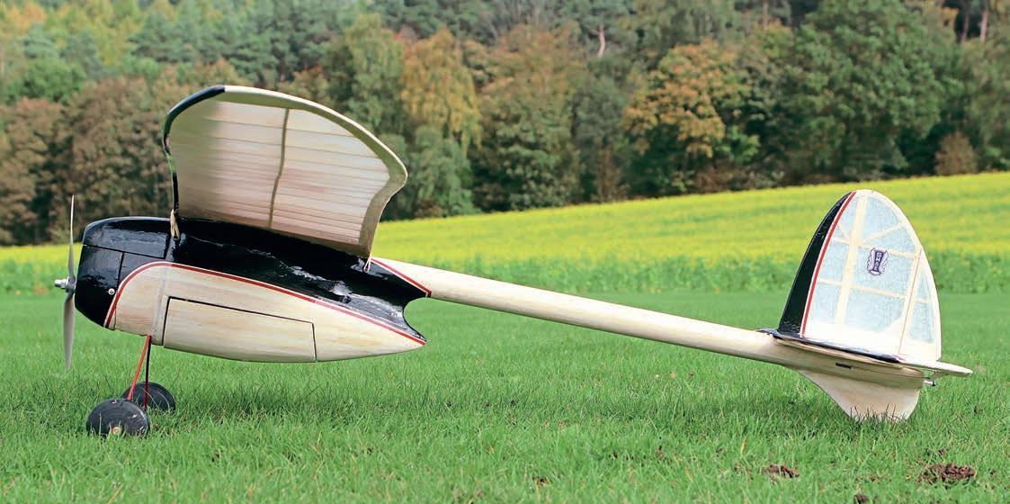
Henry Struck’s 1941 Boomer Bus was designed for IC power but makes an ideal vehicle for a modern electric conversion. A ‘proper’ builder’s model that won’t be hurried - either on the board or in the air.
Hooper
The plan shows some rather swoopy, streamlining fillets of 1/32” balsa sheet to cover the fuselage joins and these were next on the agenda. I opted to complicate things by using 1/64” ply for these fillets as they’ll help to reinforce the joint betwixt pod and boom. Given that the fillet pieces would have to adopt a compound curve as they rounded over the fuselage, I dunked them in water overnight to try and soften them up a bit.
The next morning, I was able to persuade the first fillet to conform to the desired, concave shape. Using a combination of glue, pins, scraps of balsa dowel and elastic bands, I secured the fillet in place whilst the glue dried. The opposing fillet, on the other side of the fuselage, followed suit a day later. After all, we’re not in a rush, are we?
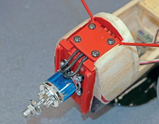
The ply motor box has 3° of downthrust built into it and I eyeballed in a little bit of side thrust too using packing washers under the motor’s lugs. Using the prop adapter as a foundation, I cut a tear-drop shaped piece of 1/16” ply to act as a front former and bolted this to the front of the motor. Installed, and with the front former vertical, I wrapped the motor with masking tape, not only to stop it rotating but also to keep the inevitable sawdust out of its innards.
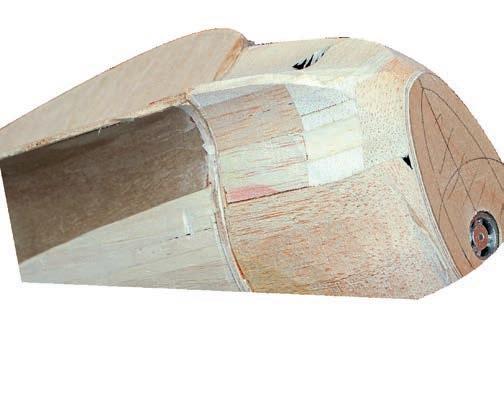
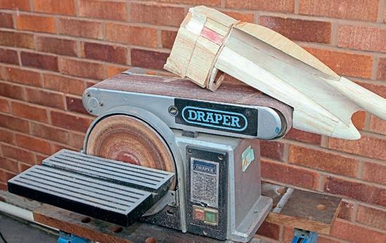
OVAL COWL
That unusual cowl was formed from scrap balsa block and I used the old trick of applying Sellotape to the motor box where I didn’t want the cowl to be installed permanently, prior to building the cowl in situ. The most joyous part of the project so far was breaking out the belt sander, then roughing out the shape of the cowl. It’s quite intricate, with three areas that are concave, so I carefully used the very end of the belt where it passes over the end roller to give a tighter internal radius.
As space was tight in the nose, I spent some time pondering the fitment of the ESC and its attachment to the motor’s wires. After trying out various ideas for routing the wiring, I hit on the idea of passing the three cables under the cowl, and then between the undercarriage and its mounting plate, and then into the front of the pod. The only snag with this scheme was that the wires would interfere with the front face of the large belly hatch, so I fabricated an internal, open-fronted box in the hatch to accommodate the ESC cables.
Tail Mount
Whilst I pondered the cowl and hatch, part of me was also wondering what to do at the tail end of the boom about mounting the tail surfaces. Should the tail set be fixed in place or removable. Where to run the control linkages? The original design calls for a banded-on tail set in the interests of free flight flexibility. But that can inevitably lead to unwanted movement and loss of trim settings.
Whilst I deliberated all these esoteric issues, I ploughed ahead and fitted a curved mounting plate, which was inset into the top of the boom. The plate matches the curvature of the underside of the tailplane pretty exactly. This was achieved by using the tailplane itself to hold the mounting plate in place as the glue dries.
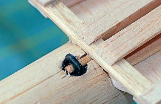
Very nice, but it still didn’t help my dilemma very much. Eventually, I hit upon what seems to be a reasonable compromise - a dowel at the leading edge and a piano wire clip at the rear.
Given that there’s a gap between the tailplane’s central ribs to create a slot for the fin to sit in, I glued a length of bamboo skewer chord-wise on the lower surface, with front and rear ends protruding. A quick rummage in the gubbins drawer yielded a short wing bolt with a flattened finger grip, which I was able to drill to accept the dowel. I then drilled into the top of the boom, and into the central keel, and let the wing bolt self-tap itself downwards. With the drilled finger grip set at 90°to the boom I can slip the tailplane’s front dowel in place, leaving just the trailing edge to accept the swinging clip.


Cover Up
With all the airframe’s components pretty much sorted, I had a think about the covering material. Thinking back, our last foray on the Ghost Rider project led me, once again, to go the Doculam/tissue route on the open-framed areas of the flying surfaces.
The underside of the wing came first. Given that its gull-wing format gave it a large undercamber when viewed from the front, I applied the Doculam working from the centre outwards, tacking it to each rib in turn, before zapping the whole panel, one rib bay at a time with the heat gun. The wing’s top surface was treated similarly, although I only covered the open areas rear of the top spar.
Carnival Papers tissue was next on the agenda. Previously I’ve applied this budget paper pre-damped and doped it in place. This method works well but can leave the tissue with a mottled, bloomed finish.
This time I applied the tissue dry and attached it to the edges of the framework with a glue stick. Only then was it sprayed with water. The underside of the wing panels was no problem but I was expecting to struggle with the cambered top surfaces. I covered each top surfaces in three separate pieces of tissue to minimise the amount of shrinkage required.
The end result does have a few wrinkles, it’s true, even after a couple of coats of thinned, shrinking dope. More surprising was that even though the wing panels were pinned back in station on that bent building board as the dope dried there’s a significant, but equal, amount of washout on both panels.
The leading edge of the wing was covered in span-wise strips of black Profilm, followed by a thin trim line of red Solartrim. An appropriate logo was comped up on the Cricut vinyl cutter and the end result looks pretty swish, I think.

The fuselage and access hatches were covered by simply doping on panels of tissue paper. This took longer than expected, I’ll confess. The interior of the cowl was given a coat of fearsome red enamel, as was the undercarriage.
What did show through the tissue finish on the pod, though, were those streamlining fillets of dark brown ply. So, I masked some swoopy curves with low tack masking tape and filled them in with water-based black enamel. There was a little bit of bleeding under the tape afterwards but a gentle scrape with a knife point got rid of most of this. Red Solartrim pin stripes followed the outline of the black areas and I used a coolish iron to coax the tape around the curves, sticking it in position as I went along.
Final Assembly
The next stage was final assembly. Experience tells me that even though I’ve assembled the airframe and all its fittings several times already, and so this should be the work of a single evening, the final fit-out always seems to take ages.
First up came those skinny pushrods and the question of just how to fit them inside that long boom now that both ends were sealed. The penny dropped that all I needed to do was to drill two holes in the front bulkhead so I could feed the rods in from the front and then guide their rear ends out through slots in the tailplane area.
The elevator pushrod is dead conventional and exits beneath the tailplane. But the rudder rod is a little less aesthetically pleasing in that it runs over the top of the tailplane. No matteras long as it works as it should.

Suddenly, I had a completed aeroplane on the bench! I eyeballed the CG position and added a lump of lead within the cowl to drag it forwards to around 35% of the chord, which seemed about right. Completed weight (including the 3S 1800mAh LiPo) turned out at 29oz and with 170 watts on tap I had no worries about the power loading.
Just to be on the safe side I screwed a chunk of lead to bring the CG forwards a little.
SUNNY MAIDEN
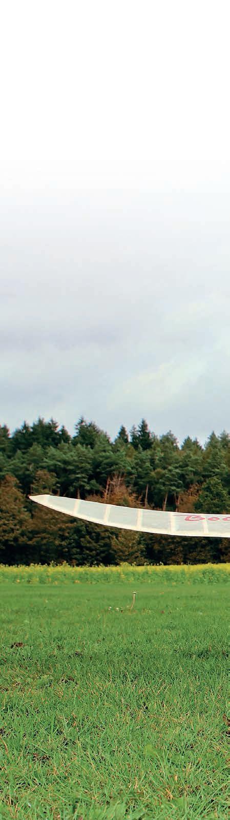
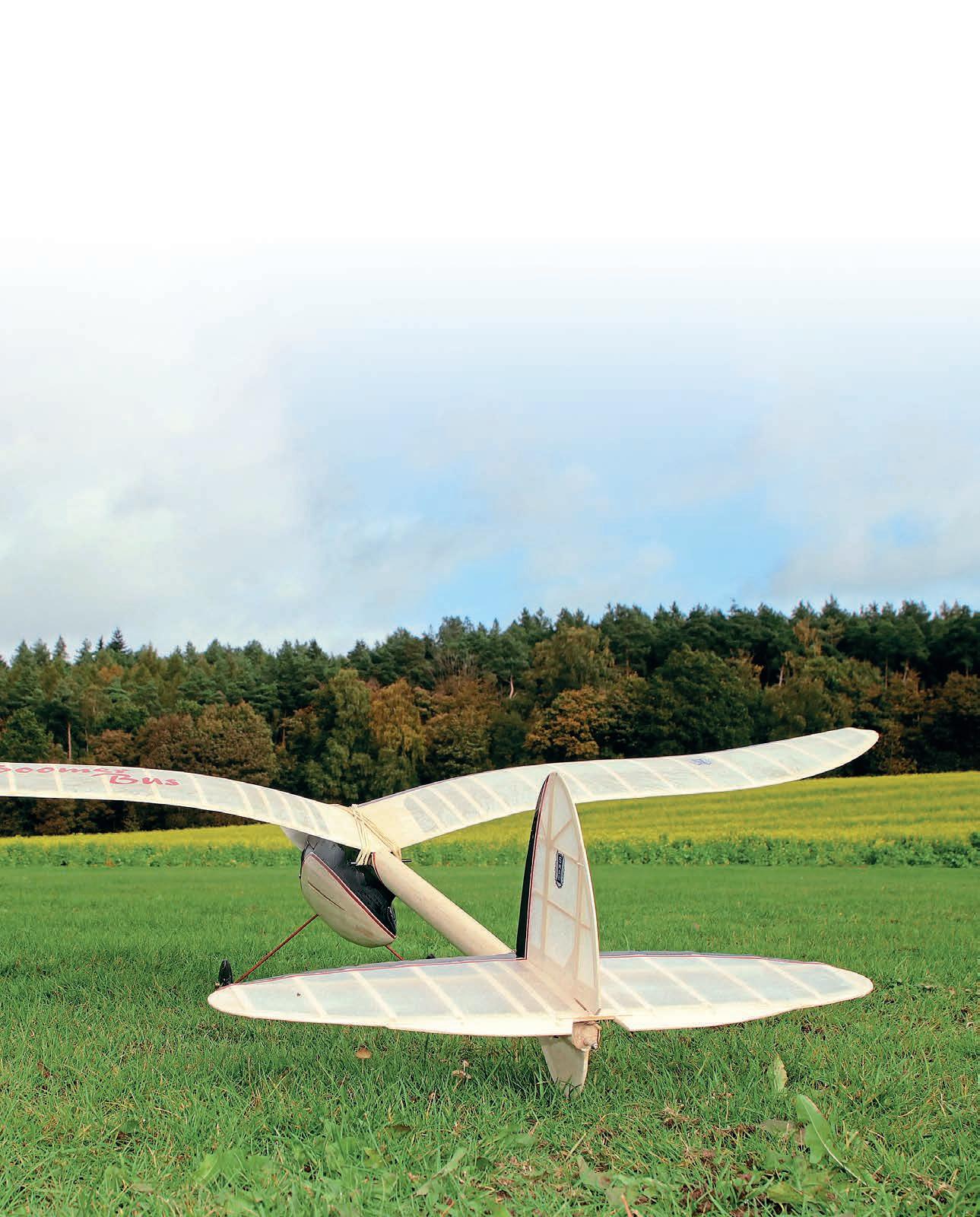
The very next day happened to be a sunny Saturday and so the Boomer Bus was taken to the field for its debut. I was a bit hesitant, given the gusty crosswind, but having taken the static shots I braced myself appropriately and took the Bus out to the flight line.
I opted for a pukka take off, as opposed to the relative safety of a hand launch and pointed the model into the wind. As the throttle was eased forwards the Bus tracked dead straight for a few yards and then lifted cleanly, heading skywards in a perfectly straight line.
The remainder of the maiden saw quite a few circuits at a reasonable height. I didn’t risk any low camera passes in the crosswind. The landing was simple and gentle, with no drama. Subsequent flights were with my clubmate, Trevor, on the sticks whilst I took a few snaps. Trev remarked that the Bus was remarkably smooth and relaxing to fly, which is very affirming, because he’s not an easy bloke to please. Should I have done anything different? Well, even on full rates, the rudder is very soft - more advisory than authoritative. So, yes, if I’d been a bit smarter, I’d have made the rudder about
50% larger, which would help at low airspeeds, such as when making that final turn into wind when on the landing approach. Never mind, she’ll stay as she is!

So, there’s another keeper for my everincreasing fleet of oddball vintage models.
O&R SPARKIE
Ever start a job that should be oh-so-simple, but which turns out to be a lengthy saga instead?
Some while ago my old mucker, Ian Easton, sent me a rather splendid Ohlsson & Rice .23


