8 minute read
SYSTEMS


Poor pipeline design or improper application of a pump bring about many of the problems experienced by pump users. Taking care when designing the layout of the total system and adhering to good pumping practice will result in a comparative improvement of performance. Pumping systems, irrespective of the type of pump used, can be split into two fundamentally different sections: the suction and the discharge.
The suction is the part of the system between the source of the liquid to be pumped and the pump itself. When the pump is located above the liquid source, it is said to operate with a suction lift. When the pump is located below the liquid level, it operates with a suction head.
Advertisement
The rest of the system constitutes the discharge.
Suction pipework

There are a number of key points to keep in mind when designing the system:
• It is good practice to keep the suction pipe as short and straight has possible
• The pump should operate with a suction head where possible
• Eliminate all possibility of air pockets being trapped in the suction pipework
• When bends in the suction pipe are unavoidable, priming valves, and nonreturn or foot valves must be fitted to the line in the correct position, otherwise the pump may not prime
• The suction pipe should be accessible
• When selecting foot vales, strainers, bends, etc., select ones that will provide minimal restriction to flow
• Some care must be taken in the design of the solution inlet
Furthermore, the diameter of the section pipe should be sized according to the flow and allowable head loss; in any case, it should be equal in diameter to the pump inlet connection.
If the pipe is larger than the pump inlet, it is good practice to fit an eccentric reducer to avoid the possibility of air pockets.
Discharge pipework
Discharge pipeline should be designed to minimise losses. All bends, valves, strainers, reducers and other fittings in the line contribute to friction losses.
Accurate calculation of friction losses is essential, and it follows that the characteristics of the liquid to be pumped must also be considered.
The PIA’s Pipe Friction Handbook, available to purchase from pumps.org.au/publications, presents a comprehensive tabulation of head losses that can be expected for given flow rates in commonly used pipes and fittings.
Selecting the pipe
Several factors need to be considered when selecting the pipe:
• Fluid: viscosity, temperature, chemical properties, flow rate, pressure
• Pipe: length, roughness, strength, cost
Of these factors, temperature and chemical properties of the fluid will probably determine the material the pipe is made of, or at least exclude the use of certain materials. For example, plastic pipes would not be suitable for applications pumping oil at 300°C. The pumping of high viscosity fluids increases the friction head, and may require a larger diameter pipeline and long radius bends to be used.
While high friction loss can be tolerated in short lengths of pipe – such as can be found in processing plants –on longer pipelines, like those for water supply, friction is a major part of the total head and should be kept to an economic minimum. An average velocity in the pipe of 2m/s is usually acceptable when pumping over long distances.
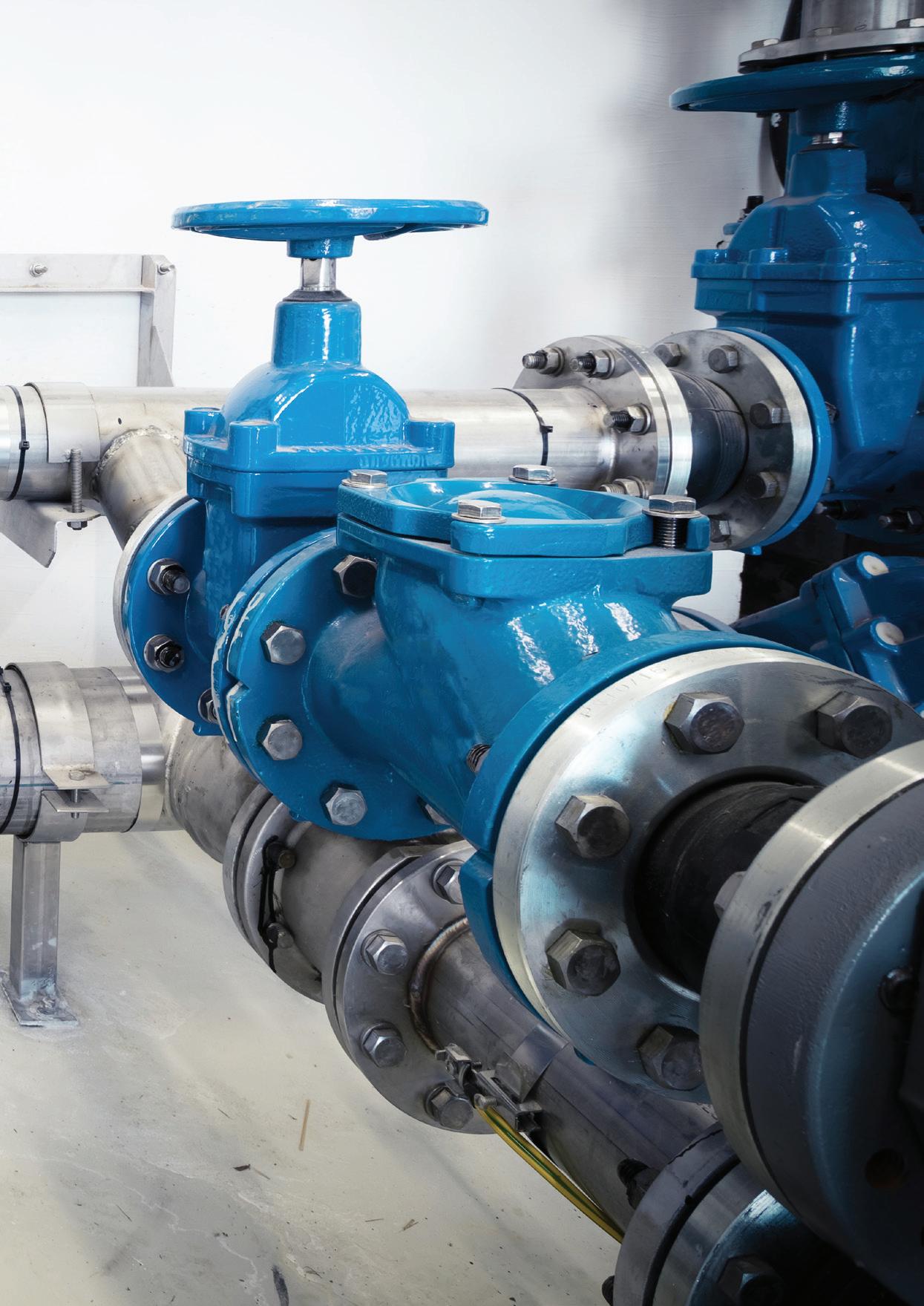
Valves
It is recommended that a centrifugal pump is fitted with a non-return valve at discharge. When the pump is shut down, the valve prevents reverse rotation of the pumpset and possible damage to the pump and/or driver depending on the mechanical arrangement.
Valves should be installed in a way that the pump can be isolated for maintenance and inspection.
Air vent valves
Pipelines that have crests and troughs should be fitted with an air vent valve at the highest points to allow accumulated air or other gases to escape from the pipe. These valves should be fully automatic and close when liquid enters the valve.
Branch connections
If it is necessary to pipe liquid to more than one discharge point, a ‘Y’ type connection should be used to reduce losses at the branch.
Reduction of pipe diameter
If a number of branches are taken off the main pipeline, it may be possible to reduce the diameter of the main pipe as it can be sized to suit the reduced flow.
However, sudden changes in diameter need to be avoided as these produce friction losses. Therefore the change in diameter should be effected gradually by a taper piece. In order to get the best results, the included angle of the taper piece should be 10-13°.
Thrust blocks
Regardless of whether the pipes are laid above or below ground, adequate support and anchorage for the pipes must be provided. Detailed requirements should be sought from the pipe manufacturer to ensure that no mechanical or hydraulic loads are imposed on the pump.
Particular attention should be given to pipework design where anti-vibration devices are incorporated.
If flexible piping is used, particularly on the discharge of a pump, it must be adequately supported and restrained. For example, the coupling alignment may be correct when the pump is shut down, but becomes badly misaligned when flexible hoses are allowed to impose forces on the pump during operation.
Special considerations
There are certain aspects of pump and pipeline design that require special consideration, and these are usually related to the liquid being pumped. In these instances, the pump manufacturer should be consulted.
Pressure surges and waterhammer
Any system in which a fluid is in motion or capable of being set in motion is susceptible to pressure surge or waterhammer. Surges occur whenever the velocity in a conduit changes from one steady state to another. The most severe conditions will most likely correspond to the pump starting or stopping or the ‘instantaneous’ opening or closure of a valve in the pipeline.
The effects of pressure surges in a system can be compared with the forces on a moving vehicle during periods of acceleration or retardation. For example, when a vehicle is brought to rest by the brakes being applied suddenly and violently, severe stresses are imposed on parts of the vehicle. In the context of a pumping system, the system may be subject to quite dangerous pressures during acceleration and retardation of liquid in pipes.
Accordingly, if a valve is slammed shut at the end of a delivery line, a transient surge or wave resulting from the sudden gate closure moves towards the pump. If the pipe walls are rigid and inextensible, the speed of the pressure wave would approach the velocity of sound in the liquid – about 1,400m/s for water – and since the magnitude of the pressure rise in the pipe due to instantaneous gate closure is proportional to the speed of the wave and change in water velocity, then extremely high pressures can be propagated. Consequently, if those pressures are not properly controlled they may cause noise and vibration in the system, piping to burst, or pump casing to crack.
Waterhammer calculations are complex so it is recommended that specialised engineering services are employed in cases where it may be a problem.
It should be noted that waterhammer effects are always possible and may determine the design loads for a system. The pipeline longitudinal profile is also important and route selection could be influenced by the waterhammer implications.
Discharge of syphon lines
Syphon lines are often used in groundwater pumping stations to feed the discharge from industrial wells or boreholes into a collecting well from which the water is then pumped into a reservoir.
Equations are available to find the maximum static suction lift allowable for satisfactory operation without damage to the pump. These equations and examples can be accessed in the Pump Technical Handbook.
Further information and detailed diagrams, equations and schematics can be found in the Australian Pump Technical Handbook, available at pumps.org.au/publications/. The Handbook has recently undergone an update, with the new sixth edition available now. In the next edition of Pump Industry, we take a deep dive into intake design.
The pump industry relies on expertise from a large and varied range of specialists, from experts in particular pump types to those with an intimate understanding of pump reliability; and from researchers who delve into the particulars of pump curves to experts in pump efficiency. To draw upon the wealth of expert knowledge the Australian pump industry has to offer, Pump Industry has established a panel of experts to answer all your pumping questions.
In this edition of Ask an Expert, we will look at custom-built progressive cavity (PC) pumps for oil and gas applications. The oil and gas industry uses PC pumps to convey sludge or oily water and in specific circumstances such as when light hydrocarbons raise the vapour pressure to a level where other pump types would cavitate.
Q: What credentials, product experience and services should a customer look for in a pump manufacturer?

A: Since oil and gas applications are complex with a high level of documentation, I recommend finding a reliable partner with many years of experience and high-quality products that excel in harsh conditions. A manufacturer with a dedicated sales and project management team, or better still, a dedicated engineering and document handling team can provide first-class order processing capabilities for complex projects along with specification compliance and quality requirements typical of the industry. Local offices and partnerships in your region for quicker response times and more personalised service are key additions.
Q: What are the main reasons for using PC pumps in the petrochemical industry?
A: Manufacturers offer PC pumps, skids and systems for upstream, midstream and downstream applications. PC pumps are used in the oil and gas industry for the following main reasons:
• They provide stable performance regardless of viscosity or solids content (sand, slops, sludge, coke, catalyst, fibre) and are ideal for drain applications with polluted oily fluids of unpredictable composition and for crude oil transfer over a wide temperature range
• As they have the lowest shear rate of all pump types, they are often used to feed separators, since they do not cause emulsification of oil and water, which enables efficient separation
• They can handle the lowest NPSH and avoid/resist cavitation better than other pumps, which is useful with high vapour pressure hydrocarbon fluids
• They are the only positive displacement pumps that can be easily installed in a vertical, semi-submersed position in sumps or vessels
• They can handle very high and variable gas contents (up to 99.5 per cent gas) in multi-phase boosting systems, where they can even be used as a wet gas compressor
• They have a linear performance curve with capacity proportional to speed, which is excellent for dosing systems, in particular for the dosing of catalyst slurry
Q: Oil production presents many challenges to the producer. How are PC manufacturers helping them?
A: The focus must be on the best product quality. Premium manufacturers have pumps in their portfolio known for their reliability and good lifecycle costs, which customers appreciate. Long-term experience with the key applications allows them not only to meet the pumping challenges of the producers, but also to guide them towards the best overall solution. Some manufacturers, such as SEEPEX with its BNA pump range –tailored to the oil and gas industry – offer as standard the best API compliance. They are also able and willing to customise their designs to the customer's specifications.
Peter Vila, Managing Director of SEEPEX Australia, is a progressive cavity pump expert. He has been involved with pumps for over 40 years. Peter spent the first five years repairing pumps and the following 35 years in technical sales, 20 of which have been with SEEPEX progressive cavity pumps. For more information on progressive cavity pumps, please contact SEEPEX Australia on (02) 4355 4500 or at info.au@seepex.com


