Solutions Manual for Physical Metallurgy Principles 5th Edition by Abbaschian, Abbaschian
ISBN: 9798214001661
Solution and Answer Guide: Abbaschian, Physical Metallurgy Principles, 5e, 2025, 9798214001661; Chapter 1: The Structure of Metals
ISBN: 9798214001661
Solution and Answer Guide: Abbaschian, Physical Metallurgy Principles, 5e, 2025, 9798214001661; Chapter 1: The Structure of Metals
A BBASCHIAN , P HYSICAL M ETALLURGY P RINCIPLES , 5 E , 2025 , 9798214001661 ;
C HAPTER 1: T HE S TRUCTURE OF M ETALS
1.1
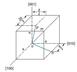
Determine the direction indices for (a) line om, (b) line on, and (c) line op in the accompanying drawing of a cubic unit cell.
Solution:
(a) The direction indices for line om are [111].
(b) The vector components of line on, in units of, a=1, are 1 , 2 1 and 0 along the x, y and z axes respectively. The corresponding direction indices are accordingly [120].
(c) The components of line op are , 21 , 32 and 1 1 Thus the indices are [436].

Solution and Answer Guide: Abbaschian, Physical Metallurgy Principles, 5e, 2025, 9798214001661; Chapter 1: The Structure of Metals
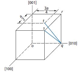
Determine direction indices for lines (a) qr, (b) qs, and (c) qt.
Solution:
1.3
Solution and Answer Guide: Abbaschian, Physical Metallurgy Principles, 5e, 2025, 9798214001661; Chapter 1: The Structure of Metals
(a) The direction indices of line qr are [001].
(b) The direction indices of line qs are [101].
(c) The direction indices of line qt along the x, y and z axes are , 11 , 24 and 1 , 1 yielding the indices 214
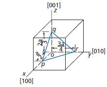
In this figure, plane pqr intercepts the x,y, and z axes as indicated. What are the Miller indices of this plane?
Solution:
The intercepts of plane pqr with the three axes are 13 24,, and , 2 3 with the reciprocals , 11 , 1/23/4 so that the Miller indices of the plane are (12 8 9).
1.4
1.5
Solution and Answer Guide: Abbaschian, Physical Metallurgy Principles, 5e, 2025, 9798214001661; Chapter 1: The Structure of Metals
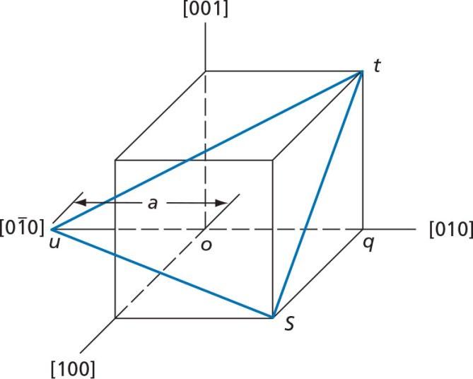
What are the Miller indices of plane stu?
Solution:
This plane has intercepts , 1 2 –1 and , 1 2 so that the Miller indices are 212
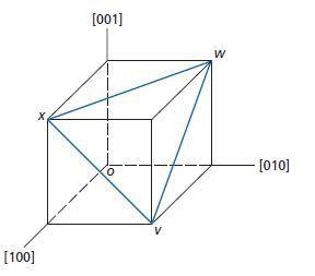
Write the Miller indices for plane vwx.
Solution:
On the assumption that parallel planes can be described by the same set of Miller indices, this plane should have the same indices as plane (C) of Fig. 1.16, which are (111).
Solution and Answer Guide: Abbaschian, Physical Metallurgy Principles, 5e, 2025, 9798214001661; Chapter 1: The Structure of Metals
1.6 Linear density in a given crystallographic direction represents the fraction of a line length that is occupied by atoms whereas linear mass density is mass per unit length. Similarly, planar density is the fraction of a crystallographic plane occupied by atoms. The fraction of the volume occupied in a unit cell, on the other hand, is called the atomic packing factor. The latter should not be confused with bulk density, which represents weight per unit volume.
(a) Calculate the linear density in the [100], [110], and [111] directions in bodycentered cubic (BCC) and face-centered cubic (FCC) structures.
(b) Calculate planar densities in (100) and (110) planes in bcc and fcc structures.
(c) Show that atomic packing factors for BCC, FCC, and hexagonal close-packed (HCP) structures are 0.68, 0.74, and 0.74, respectively.
Solution:
(a) Referring to the hard ball model of BCC structure shown in Fig 1.1c, it can be seen that the atoms touch each other along the diagonal, [111] direction, of the unit cell. Taking R as radius of the atom, its length is equal to 4R. The lattice parameter, is therefore 4R a=. 3 The edge of the unit cell, [100], is occupied by two half atoms. The linear density in [100] direction is:
For the [110] direction, the length of the diagonal of the cube face is 2, a which is again occupied by two half atoms.
The linear density along [111] direction of BCC is obviously 1. For FCC unit cell, the atoms touch each other along [110] direction, as can be seen in Fig 1.2B. The lattice parameter is therefore 42,aR = and the unit cell diagonal is
3=. 2 R a Therefore:
(b) The (100) face of the BCC unit cell, with an area of 2 , a is occupied by 4 quarter circle areas. Therefore:
Solution and Answer Guide: Abbaschian, Physical Metallurgy Principles, 5e, 2025, 9798214001661; Chapter 1: The Structure of Metals
The [110] plane of BCC has an area of 2 2. a This plane is occupied by two circles (4 quarter circles + 1). Therefore:
For FCC structure, the [100] face is occupied by 2 circles (4 quarter circles + 1).
The [110] plane of FCC again has 2 circles (4 quarter circles + 2 half circles). It’s planar density is therefore:
(c) The volume of a BCC unit cell is
The unit cell contains 2 atoms (1 center atom + 8 quarter corner atoms). The packing factor is therefore:
The unit cell of FCC structure contains 4 atoms (8 quarter atoms in corners + 6 half atoms at the center of the faces).
Since HCP has the same packaging as FCC, its packaging factor is also 0.74. this can also be calculated following Problem 1.7, by calculating the volume of the unit cell and considering that each unit cell contains 6 atoms (3 central atoms + 2 half atoms at the center of each base + 12 one sixth atoms on the corners).
1.7 Show that the c/a ratio (see Fig. 1.16) in an ideal hexagonal close-packed (HCP) structure is 1.63. (Hint: Consider an equilateral tetrahedron of four atoms which touch each other along the edges.)
Solution:
Atom A depicts the one shown in the center of the top plane in Fig. 1.16, whereas the other three atoms are the central ones within the unit cell.
Solution and Answer Guide: Abbaschian, Physical Metallurgy Principles, 5e, 2025, 9798214001661; Chapter 1: The Structure of Metals
1.8 Iron has a BCC structure at room temperature. When heated, it transforms from BCC to FCC at 1185 K. The atomic radii of iron atoms at this temperature are 0.126 and 0.129 nm for bcc and fcc, respectively. What is the percentage volume change upon transformation from BCC to FCC?
Solution:
Each unit cell of BCC iron contains 2 atoms. The volume of the unit cell is
The volume occupied by each atom is therefore
Substituting 0.126 nm for R results in:
Volume occupied per atom in BCC = 0.01232 3nm
In FCC, the lattice parameter is equal to 42, R and each unit cell contains four atoms. Therefore:
Volume occupied per atom is FCC = = 3 0.01214nm3 4 a % volume change ( ) 0.01210.0123100 =1.4% 0.0123 =
Iron shrinks by 1.4% as it transforms from BCC to FCC at 1185k.
1.9
1.10
Solution and Answer Guide: Abbaschian, Physical Metallurgy Principles, 5e, 2025, 9798214001661; Chapter 1: The Structure of Metals
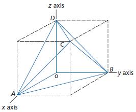
This diagram shows the Thompson Tetrahedron, which is a geometrical figure formed by the four cubic {111} planes. It has special significance with regard to plastic deformation in face-centered cubic metals. The corners of the tetrahedron are marked with the letters A,B,C, and D. The four surfaces of the tetrahedron are defined by the triangles ABC,ABD,ACD, and BCD. Assume that the cube in the above figure corresponds to a face-centered cubic unit cell and identify, with their proper Miller indices, the four surfaces of the tetrahedron.
Solution:
(a) The indices of plane ABD are (111).
(b) The indices of plane ABC are ()111.
(c) The indices of plane ADC are ()111.
(d) The indices of plane BCD are ()111.
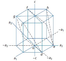
The figure accompanying this problem is normally used to represent the unit cell of a close-packed hexagonal metal. Determine Miller indices for the two planes, defg and dehj, that are outlined in this drawing.
Solution and Answer Guide: Abbaschian, Physical Metallurgy Principles, 5e, 2025, 9798214001661; Chapter 1: The Structure of Metals
Solution:
(a) Plane dehj is parallel to the 1a axis and may be assumed to intercept it at infinity. It intercepts the 2a axis at + 1, the 3a at – 1 and the c axis at + 1. This conforms to the Miller indices . 0111
(b) Plane defg makes identical intercepts with 1 , a 2 , a and 3 . a However, it intercepts the c axis at 1 . 2 + The Miller indices for this latter plane are accordingly 0112
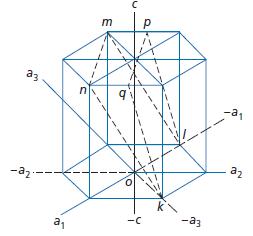
Two other hexagonal closed-packed planes, klmn and klpq, are indicated in this sketch. What are their Miller indices?
Solution:
Both plane klmn and klpq have basal plane intercepts; 1a at – 1, 2a at 1 , 2 and 3a at – 1, while their c axis intercepts are + 1 for klpq and 1 2 + for klmn. Thus, the indices are 2 111 and 2211 respectively.
Solution and Answer Guide: Abbaschian, Physical Metallurgy Principles, 5e, 2025, 9798214001661; Chapter 1: The Structure of Metals
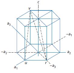
Determine the hexagonal close-packed lattice directions of the lines rt,ut, and uv in the figure for this problem. To do this, first determine the vector projection of a line in the basal plane and then add it to the c axis projection of the line. Note that the direction indices of the c axis are [0001], and that if [0001] is considered a vector its magnitude will equal the height of the unit cell. A unit distance along a diagonal axis of Type I, such as the distance or, equals one-third of the length of 2110 in Fig. 1.18. The magnitude of this unit distance is thus equal to 1 2110. 3
Combine these two quantities to obtain the direction indices of each of the lines.
The following problems involve the plotting of stereographic projections and require the use of the Wulff net, shown in Fig. 1.26, and a sheet of tracing paper. In each case, first place the tracing paper over the Wulff net and then pass a pin through the tracing paper and the center of the net so that the tracing paper may be rotated about the center of the net. Next, trace the outline of the basic circle on the tracing paper and place a small vertical mark at the top of this traced circle to serve as an index.
Solution:
(a) Consider line rt. The basal plane projection of this line equals 1 1120 3 while its c axis projection is [0001]. Adding these two components yields:
11 112000011123. 33
(b) In the case of line ut we have:
11 211000012113. 33
(c) Finally for line uv, the basal plane projection for this line equals [1010] the addition of this vector to the c axis projection is:
Solution and Answer Guide: Abbaschian, Physical Metallurgy Principles, 5e, 2025, 9798214001661; Chapter 1: The Structure of Metals
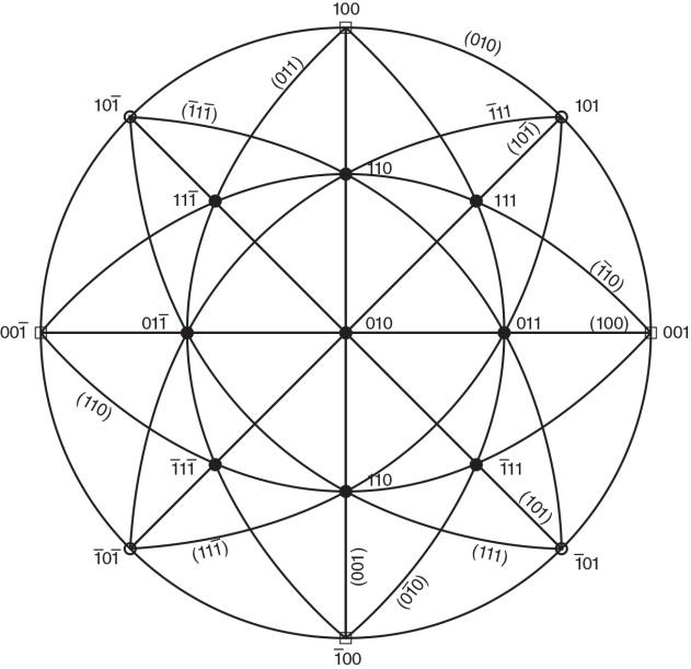
1.13 The following problems involve the plotting of stereographic projections and require the use of the Wulff net, shown in Fig. 1.26, and a sheet of tracing paper. In each case, first place the tracing paper over the Wulff net and then pass a pin through the tracing paper and the center of the net so that the tracing paper may be rotated about the center of the net. Next, trace the outline of the basic circle on the tracing paper and place a small vertical mark at the top of this traced circle to serve as an index. Place a piece of tracing paper over the Wulff net as described above, and draw an index mark on the tracing paper over the north pole of the Wulff net. Then draw on the tracing paper the proper symbols that identify the three 100 cube poles, the six 110 poles, and the four 111 octahedral poles as in Fig. 1.33. On the assumption that the basic circle is the (010) plane and that the north pole is [100], mark on tracing paper the correct Miller indices of all of the 100, 110, and 111 poles. Draw in the great circles corresponding to the planes of the plotted poles (see Fig. 1.33). Finally, identify these planes with their Miller Indices.
Solution and Answer Guide: Abbaschian, Physical Metallurgy Principles, 5e, 2025, 9798214001661; Chapter 1: The Structure of Metals
Solution:
To solve this problem, use of the Wulff net, shown in Fig. 1.26, and a sheet of tracing paper. First place the tracing paper over the Wulff net and then pass a pin through the tracing paper and the center of the net so that the tracing paper may be rotated about the center of the net. Next, trace the outline of the basic circle on the tracing paper and place a small vertical mark at the top of this traced circle to serve as an index.
1.14 Place a piece of tracing paper over the Wulff net and draw on it the index mark at the north pole of the net as well as the basic circle. Mark on this tracing paper all of the poles shown in Fig. 1.30 in order to obtain a 100 standard projection. Now rotate this standard projection about the north–south polar axis by 45° so that the (110) pole moves to the center of the stereographic projection. In this rotation all of the other poles should also be moved through 45° along the small circles of the Wulff net on which they lie. This type of rotation is facilitated by placing a second sheet of tracing paper over the first and by plotting the rotated data on this sheet. This exercise shows one of the basic rotations that can be made with a stereographic projection. The other primary rotation involves a simple rotation of the tracing paper around the pin passing through the centers of both the tracing paper and the Wulff net.
Solution:
Solution and Answer Guide: Abbaschian, Physical Metallurgy Principles, 5e, 2025, 9798214001661; Chapter 1: The Structure of Metals
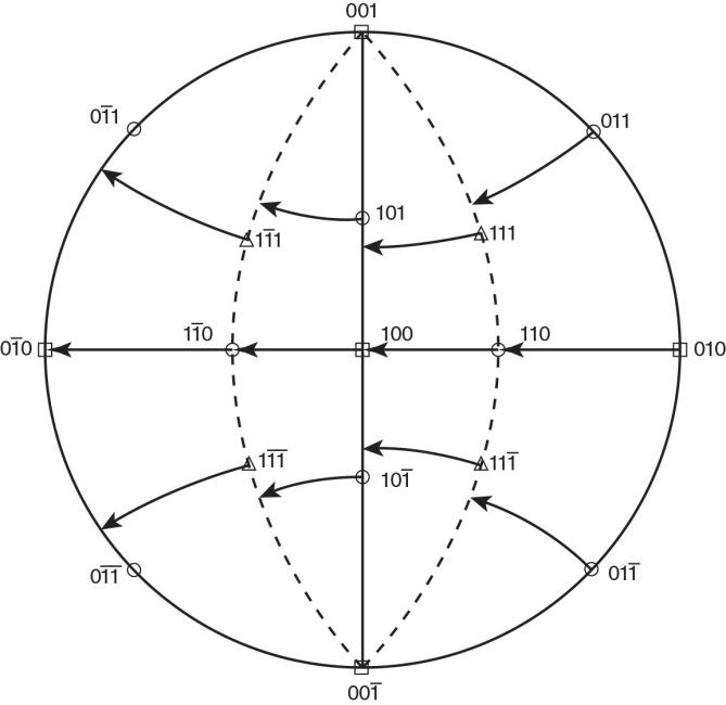
In the above figure, the 45° rotation of the poles along the small circles of the Wulff net are shown.
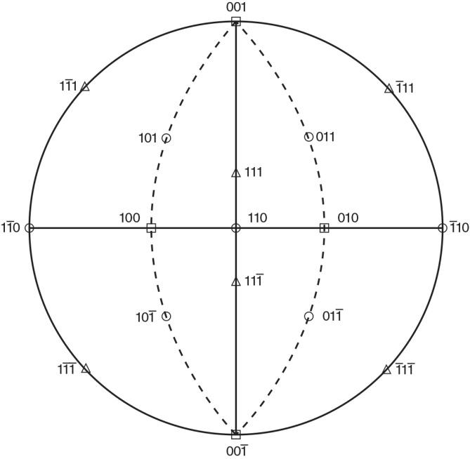
The resulting orientations of the poles, after the 45° rotation, are plotted in this stereographic projection.