Solutions Manual for Fundamentals of Mechatronics 2nd Edition by Jouaneh
ISBN: 9780357684870
ISBN: 9780357684870
By M. Jouaneh
© 2025 Cengage Learning. All Rights Reserved. May not be scanned, copied or duplicated, or posted to a publicly accessible website, in whole or in part.
1.1 Resistance Measurement
Output Voltage: 5.02 V
1 kΩ resistance: 0.997 kΩ 1 kΩ resistance: 9.967 kΩ
Nominal resistance (show calculations):
R1: ab x 10c (+/- tol%) = 10 x 102 (+/- 5%) = 1 kΩ (+/- 5%)
R2: ab x 10c (+/- tol%) = 10 x 103 (+/- 5%) = 10 kΩ (+/- 5%)
Are the measured resistance values reasonable? Explain
Yes. They are within the 5% tolerance.
1.2 Voltage Dividing Circuit
Measured value: 0.466 V
Estimated value (show work): 5.02 x 0.997/(0.997+9.967) = 0.456 V
Measured current: 0.454 mA
Computed current (show work): 5.02/(997+9967) = 0.458 mA
© 2025 Cengage Learning. All Rights Reserved. May not be scanned, copied or duplicated, or posted to a publicly accessible website, in whole or in part.
Measure the current through the 1 kΩ resistor and record below. Also write down an estimate for this current below.
Measured value: 5.01 mA
Estimated value (show work): 5.02/997 = 5.04 mA
1.4
Adjust the trigger level knob until the displayed signal appears stationary. Read the maximum and minimum voltage levels and the signal period and record below.
Maximum voltage level: 2 V
Minimum voltage level: -2 V
Signal period: 10 ms
Maximum voltage level using + operation: 4 V
1.5 Measuring AC Signals
Record the peak-to-peak voltage of the displayed signal and write it below.
Answer: 10 mV
What do you think causes the variation or noise in the displayed signal?
Answer: Noise in a DC power supply signal is mainly caused by electromagnetic interference, switching components in power supplies, or poor filtering. Load variation and transformer hum can also contribute to noise issues.
1.6* Light Bulb Activated Using Two SPDT Switches
The circuit is shown below.
© 2025 Cengage Learning. All Rights Reserved. May not be scanned, copied or duplicated, or posted to a publicly accessible website, in whole or in part.
1.1 How should you connect two resistors so that the overall resistance is larger than the resistance of either resistor?
Connect them in series since RT = R1+ R2
1.2 How is current measurement different from voltage measurement?
When measuring current, the measuring device and the circuit components are connected in a series configuration, while for measuring voltages, the voltmeter and the circuit components are connected in a parallel fashion.
1.3 What is the main difference between an oscilloscope and a multimeter?
An oscilloscope measures only voltages, while a multimeter can measure voltage, current, or resistance, depending on the selected setting. Also, an oscilloscope measures the time characteristics of a signal, while a multimeter is not designed for that purpose.
1.4 Provide an example where one needs to use the ‘+’ Math operation on an oscilloscope.
The ‘+’ Math operation can be used when one needs to see the effect of adding two signals (i.e., performing a math operation) or to check if two signals are identical by adding the inverse of one signal to the other The latter mode (using ‘+’ and ‘Invert’ together) can be used to synchronize two signals of the same frequency (adjusting the
© 2025 Cengage Learning. All Rights Reserved. May not be scanned, copied or duplicated, or posted to a publicly accessible website, in whole or in part.
magnitude of one signal until the sum is zero) or as a differential amplifier (displaying the difference at two points in the circuit.
1.5 How many circuits can an SPDT switch connect to or control in a typical electrical circuit?
An SPDT can control up to two circuits since the double throw means connection to two circuits.
© 2025 Cengage Learning. All Rights Reserved. May not be scanned, copied or duplicated, or posted to a publicly accessible website, in whole or in part.
a. Using the provided Omron relay, an SPST switch, and a small 5 V DC motor, construct a circuit that allows the motor to be turned on or off by applying a voltage to the coil leads of the relay when the switch is activated. Draw a schematic diagram of the circuit below.
The circuit is shown below.
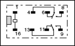
Did you hear a click when the relay was turned on? Answer: Yes
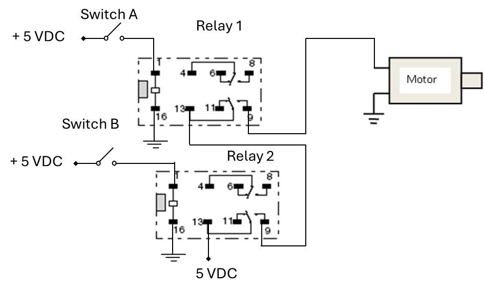
b. Construct a circuit using two Omron relays, two SPST switches (labeled A and B), and a 5 VDC motor. The circuit should be designed such that the motor turns on only when both Switch A and Switch B are simultaneously closed (on). The motor should turn off when either Switch A or Switch B is open (off). Draw a schematic diagram of your completed circuit below.
© 2025 Cengage Learning. All Rights Reserved. May not be scanned, copied or duplicated, or posted to a publicly accessible website, in whole or in part.
The circuit is shown below.
2.2 Voltage Follower
a. Construct the op-amp voltage follower circuit shown in Figure E2.2(a).
Apply the input voltages shown in the table below and record the output voltages.
b.
Measure the voltage at point A using both the multimeter and the oscilloscope. Record the values below.
Voltage as read by oscilloscope: 1.72 V
Voltage as read by multimeter: 2.40 V
© 2025 Cengage Learning. All Rights Reserved. May not be scanned, copied or duplicated, or posted to a publicly accessible website, in whole or in part.
Est. voltage from theory: 0.988 MΩ/(0.981 MΩ + 0.988 MΩ) x 4.92 V = 2.47 V
Note that the supply voltage is 4.92 V.
Are the measured voltages the same as the estimated voltage? If not, why are they different?
Answer: No, and they are different because of the loading effects caused by the circuit's high resistance.
Connect a wire between point A and the input to the voltage follower circuit that you built in Exercise 2.2a. Measure the voltage output of the voltage follower using both the multimeter and the oscilloscope. Record the values below.
Voltage as read by oscilloscope: 2.48 V
Voltage as read by multimeter: 2.46 V
Are the measured voltages now the same as the estimated voltage? What causes the improvement?
Answer: Yes, and the improvement is due to the use of the voltage follower, which significantly reduces the circuit's resistance, as seen by either measuring instrument.
2.3 Inverting Op-amp
Voltage at node A: 0.0 V
Voltage at node B: -2.0 V
Replace the 1 kΩ resistor R2 with a 5.1 kΩ resistor. What is the voltage now at point B? Is there any relationship between the resistor values R1 and R2 and the output voltage?
Voltage is -10.5 V. The output is a negative multiple of the ratio of R2/R1.
Rather than using a fixed DC voltage as the input, use a signal generator to apply the input voltage, and an oscilloscope to monitor the output voltage. Try square and triangular signals of different amplitudes and frequencies and comment on the observed output.
The output is an inverted image of the input signal.
© 2025 Cengage Learning. All Rights Reserved. May not be scanned, copied or duplicated, or posted to a publicly accessible website, in whole or in part.
Let V1 and V2 be 5 VDC each. Measure the output voltage Vout here: -10.3 V
Now make R3 = 2 R1, repeat the , and write the value here: -7.7 V
Explain the data you obtained:
The output of this circuit is VO = -Vin (R2/R1+R2/R3). For R1 = R2 = R2, VO = -2 Vin. For the second case, VO = -1.5 Vin
2.5* Differential Op-Amp
a. Record the data in the table below.
Do the values of the measured voltage agree with theoretical predictions? Yes, the output should be R2/R1(V2-V1) = (V2-V1).
b.
Now use two 1 kΩ resistors in series to make R2 = R4 = 2 kΩ. Repeat the measurements for the output voltage Vout and record the data in the table below.
Write an expression for the expected Vout as a function of V1 and V2. Do the values of the measured voltage agree with theoretical predictions? Explain.
In this case, the output should be R2/R1(V2-V1) = 2 (V2-V1), which matches the data.
© 2025 Cengage Learning. All Rights Reserved. May not be scanned, copied or duplicated, or posted to a publicly accessible website, in whole or in part.
2.1 What factors influence the current through a relay coil when actuated by a DC voltage?
When powered by a DC voltage, the current through a relay coil depends on the coil's resistance and the applied voltage. Any additional resistors or components in the circuit will also affect the current. The coil's inductance can influence how quickly the current reaches its steady state when the relay is activated.
2.2 For what purpose can an inverting op-amp circuit be used?
An inverting op-amp circuit is typically used for amplification purposes or inverting a signal
2.3 Can the output of an op-amp circuit exceed the supply voltage?
No, the output saturates slightly lower than the supply voltage.
2.4 For what purpose can a voltage follower op-amp circuit be used?
It can be used as an interface to reduce loading effects. The output of a voltage source can be connected to the follower input to isolate the source from the rest of the circuit, or the follower output can be connected to a high-impedance circuit.
2.5 How can you modify an inverting op-amp circuit to obtain a positive output voltage when a positive input voltage is applied to the circuit?
Add another inverting op-amp circuit with a unity gain in a cascade fashion.
2025 Cengage Learning. All Rights Reserved. May not be scanned, copied or duplicated, or posted to a publicly accessible website, in whole or in part.
3.1 Diode Output Current Characteristics
a.
What did you notice? Explain: The diode allows current flow in only one direction. The current did not flow for voltages <= 0.2 V and only began to flow at 0.4 V. At 0.6 V, the current flow began to get large. This diode only allows current flow due to positive voltages greater than its “forward voltage.”
What is the forward voltage (VF) for this diode? Around 0.6 V
For the case of 10-volt input, compare the measured current against the calculated current (show your work).
Calculated current = (10 – VF)/1000 = (10-0.6)/1000 = 9.4 mA, which is very close to the measured value of 9.37 mA.
b.
The input-output plot should look as shown below.
© 2025 Cengage Learning. All Rights Reserved. May not be scanned, copied or duplicated, or posted to a publicly accessible website, in whole or in part.
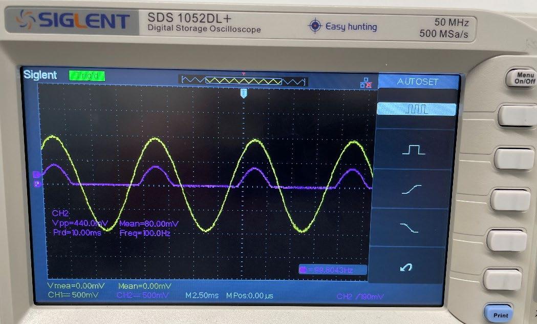
Explain the differences between the output and input signals:
The negative portion of the sinusoidal input voltage is eliminated. The amplitude of the positive portion of the output signal is smaller than that of the input signal (0.4 V vs. 1 V) because rectification occurs only if the amplitude of the sinusoidal input signal exceeds the forward voltage (VF) value for the diode.
3.2 Different Diode-Resistor Circuits
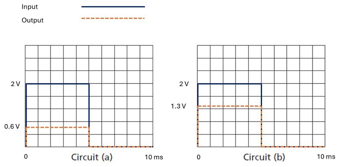
Plot both the input and the output voltage over one complete cycle.
© 2025 Cengage Learning. All Rights Reserved. May not be scanned, copied or duplicated, or posted to a publicly accessible website, in whole or in part.