2 minute read
Overallstrategy

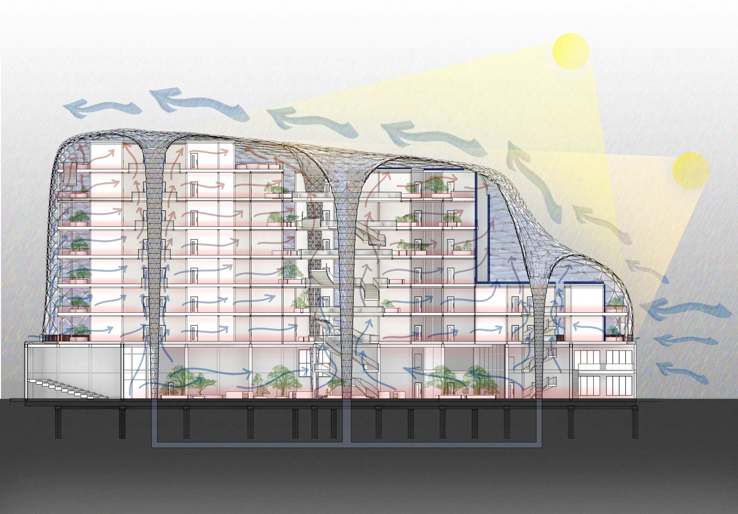
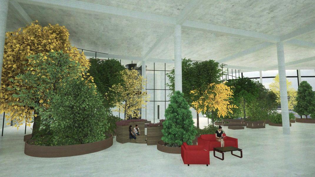
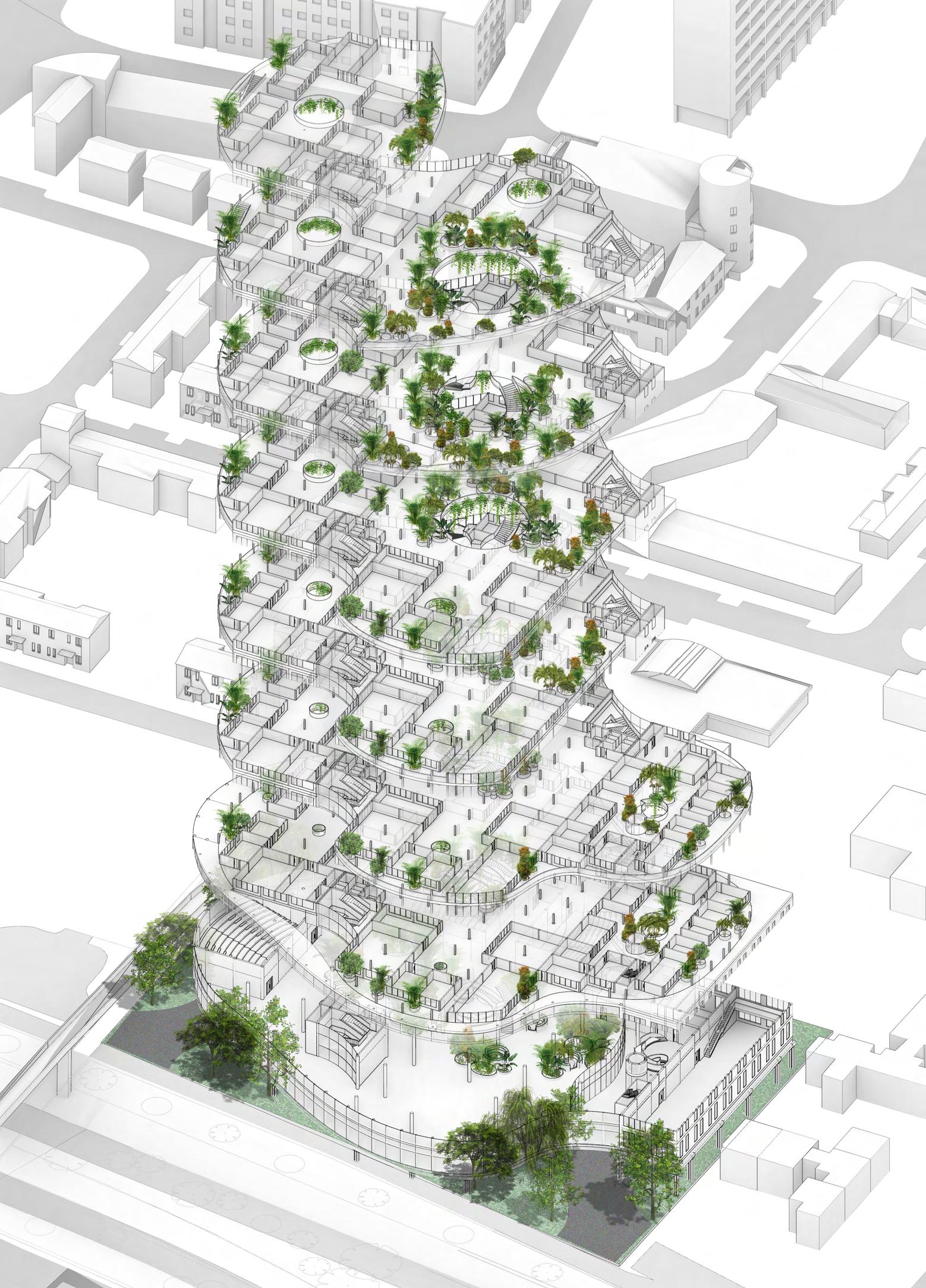
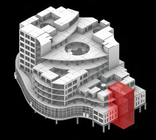
The exploded axonometric drawing displays the general landscaping strategy of the entire building. There will be replanted trees from the site around the entrances. Most of the landscaping is placed inside the building to make the vegetation feel more accessible for the users and create a natural and green interior atmosphere. The ground floor will accommodate taller trees and conversation pits that sink into the ground; it will produce a level hierarchy that adds a more interesting spatial perception.
Advertisement
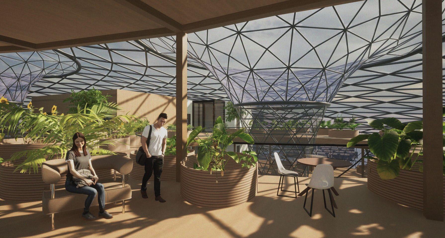
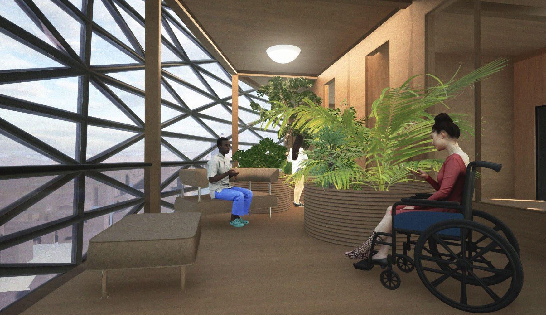
On the upper floors, there are large pots of tropical plants strategically placed around the atrium and the balconies to benefit from the sunlight. As the floors rise, the concentration of the vegetation will increase. I chose to use tropical plants after a consultation with a landscape architect, considering the interior temperature, humidity, and light exposure. Additionally, a visit to the Winter Garden in Sheffield impacted my interior landscaping design.
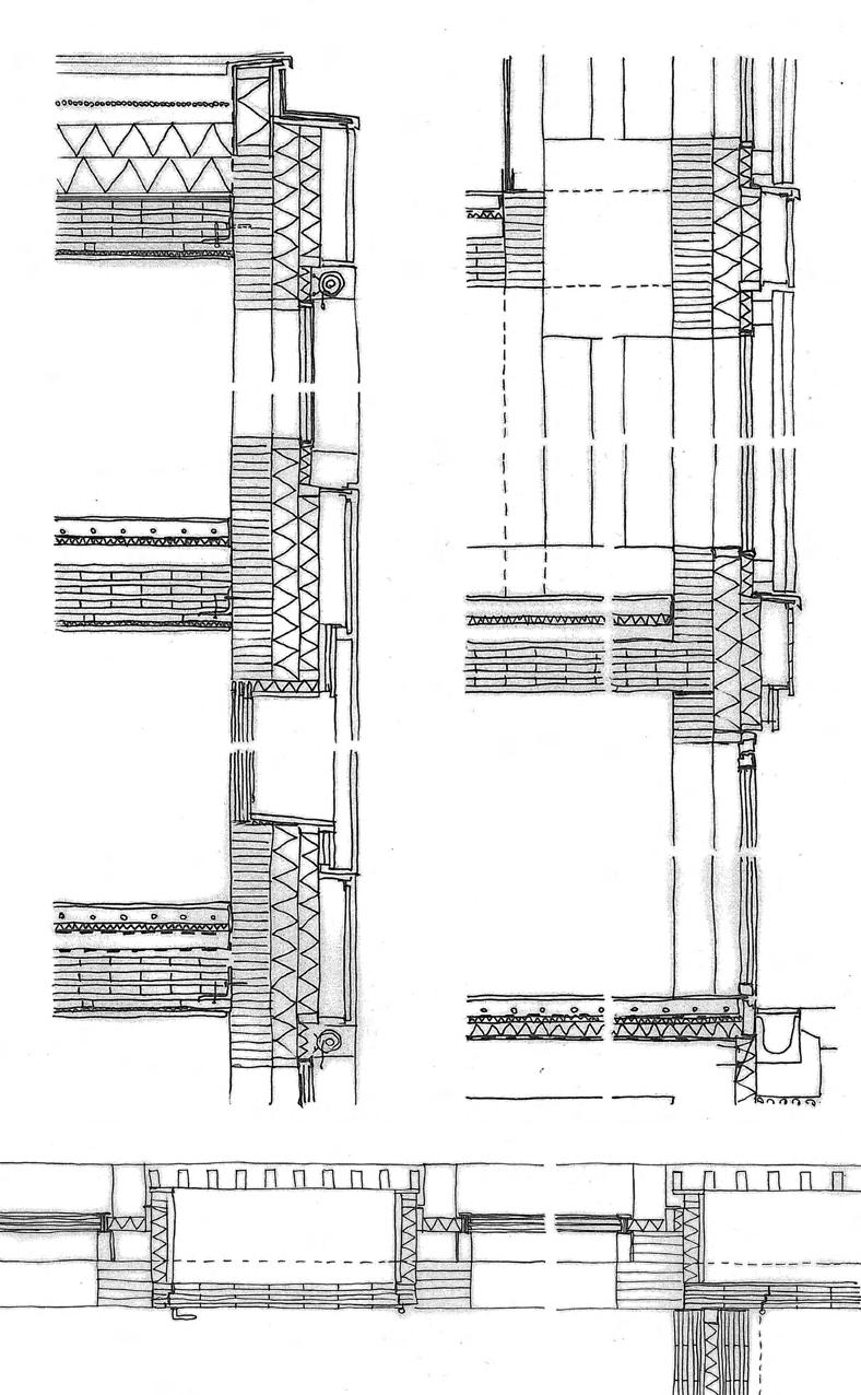
As a precedent study, I have looked at the construction details of the Holztechnikum Kuchl (HTL, technical school, boarding school, master craftsman school) in Salzburg, Austria by LP Architektur to investigate the details of timber construction.
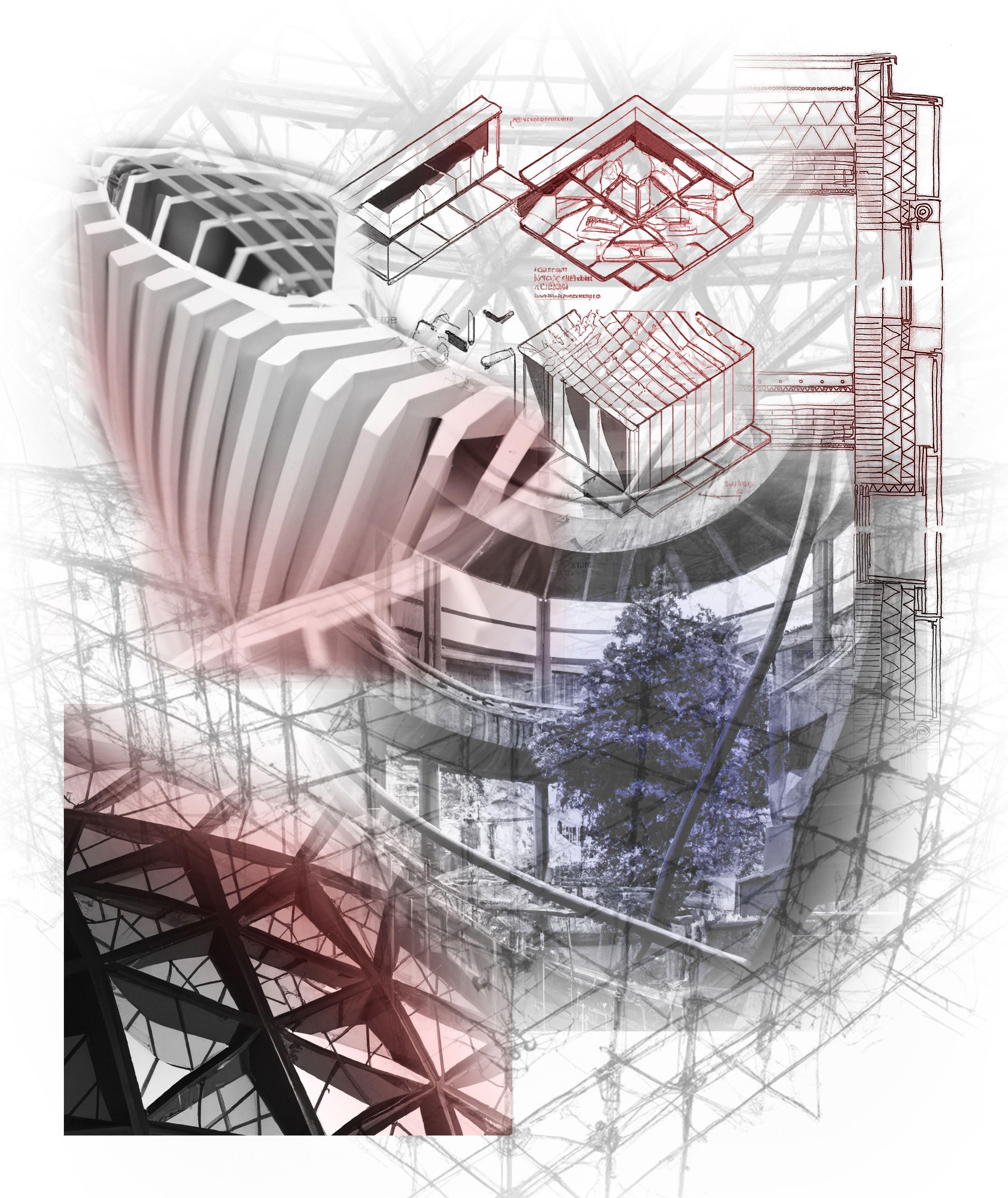
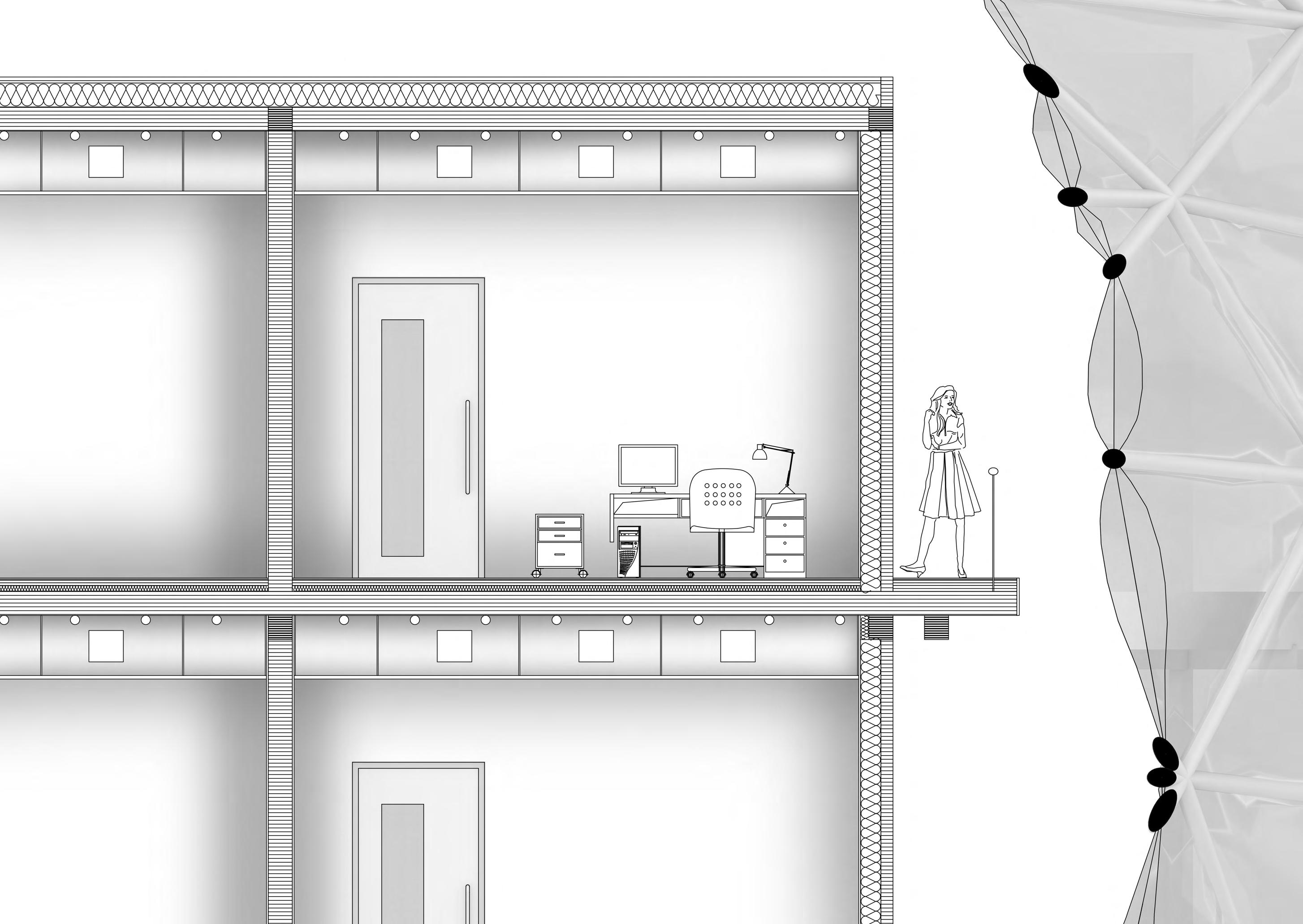
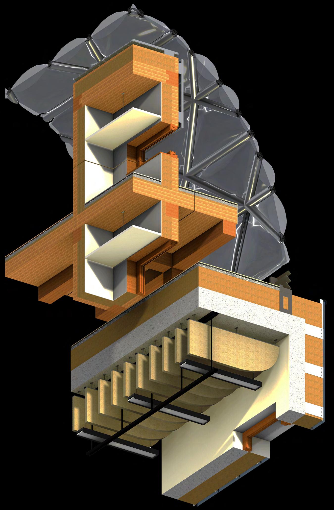
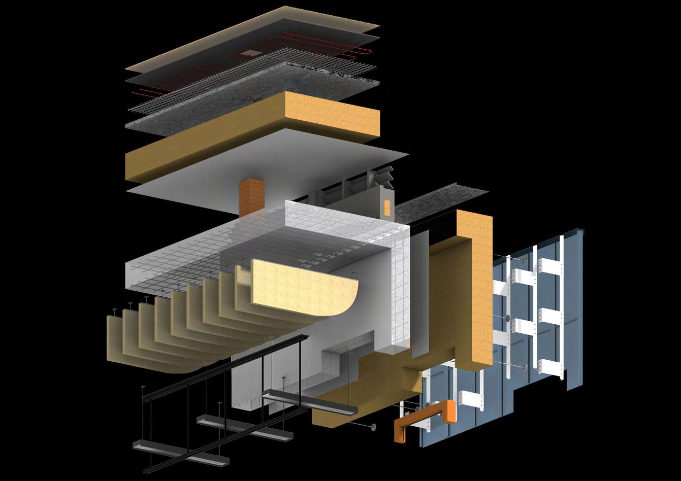
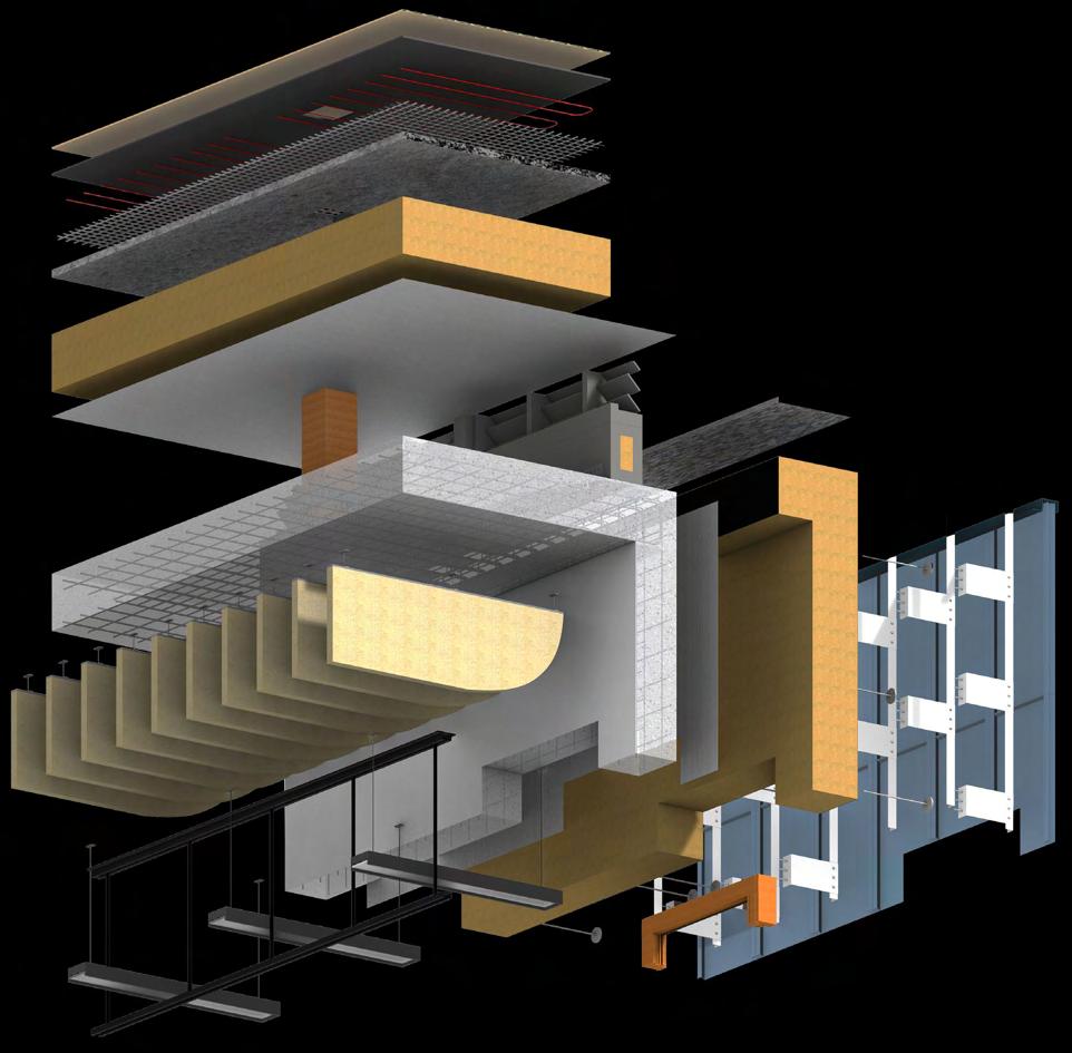
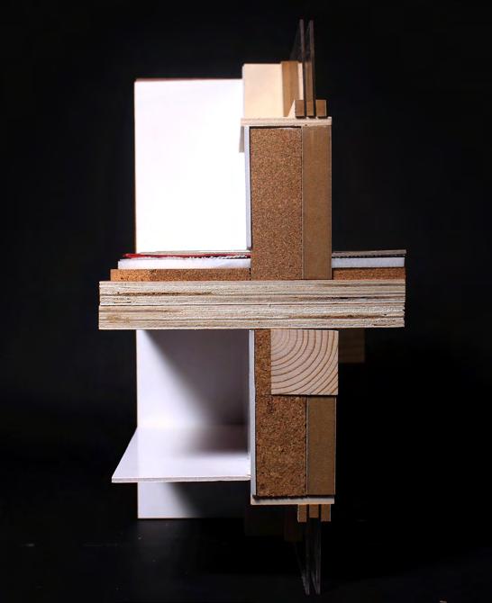
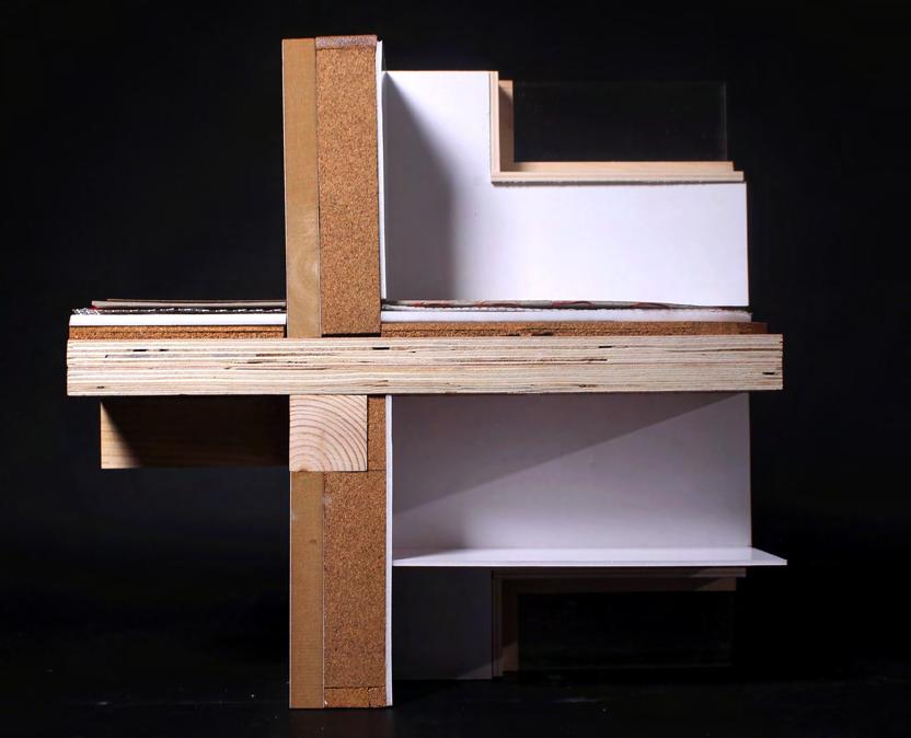
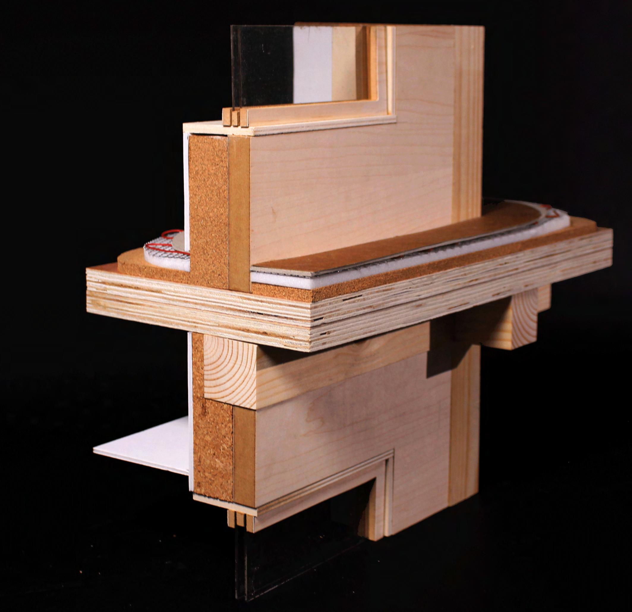
The 1:20 section shows the material build-up and services of the clinic consultation rooms. As the internal structure is weatherproofed by the ETFE facade, there was a possibility to use a minimal amount of materials internally. To retain the natural finish of the CLT and glulam, I decided to leave the components exposed in the public areas. The professional rooms on the other hand have various finishes depending on the specific requirements. The rooms are wellinsulated to reach Passivhaus standard U value to stay thermally efficient and reduce energy needs as well as avoid cold bridging. The material choices, thicknesses, and purposes will be discussed more in-depth on the 1:5 tactile detail page.
30 mm timber roofing
The roofing protects the insulation and creates hard and level surface for the roof services.
Detail location key
100 mm CLT wall
Section
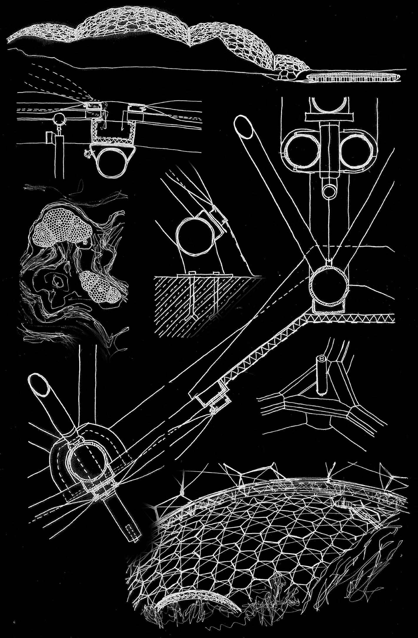
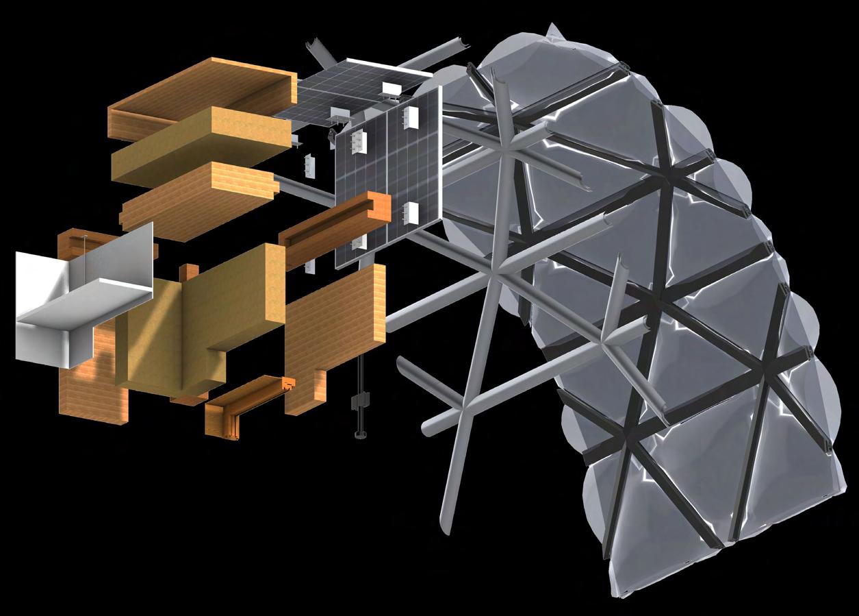
The next precedent I studied was the Leicester Space Center. I primarily explored the technical detail of the ETFE cushion clipping system and its connection to the primary structure.

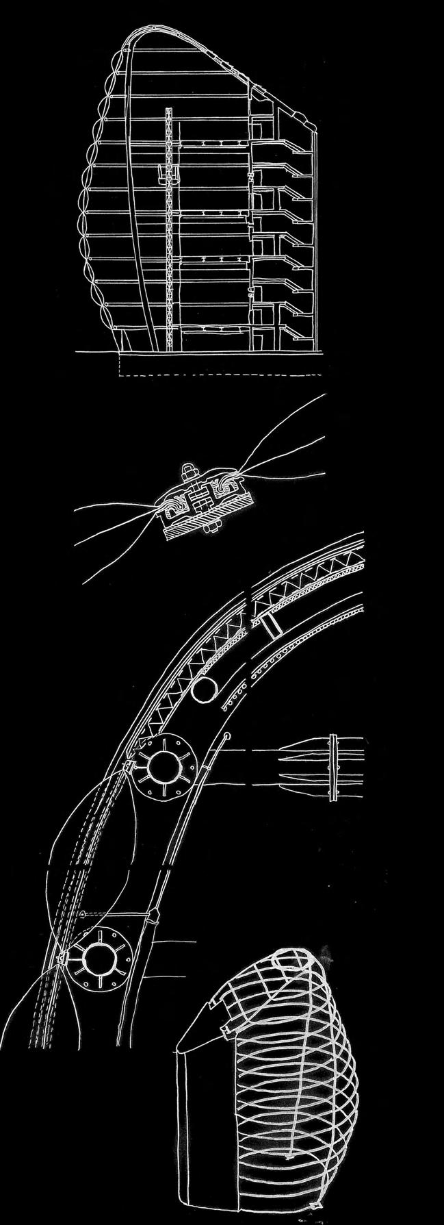
Clipping detail
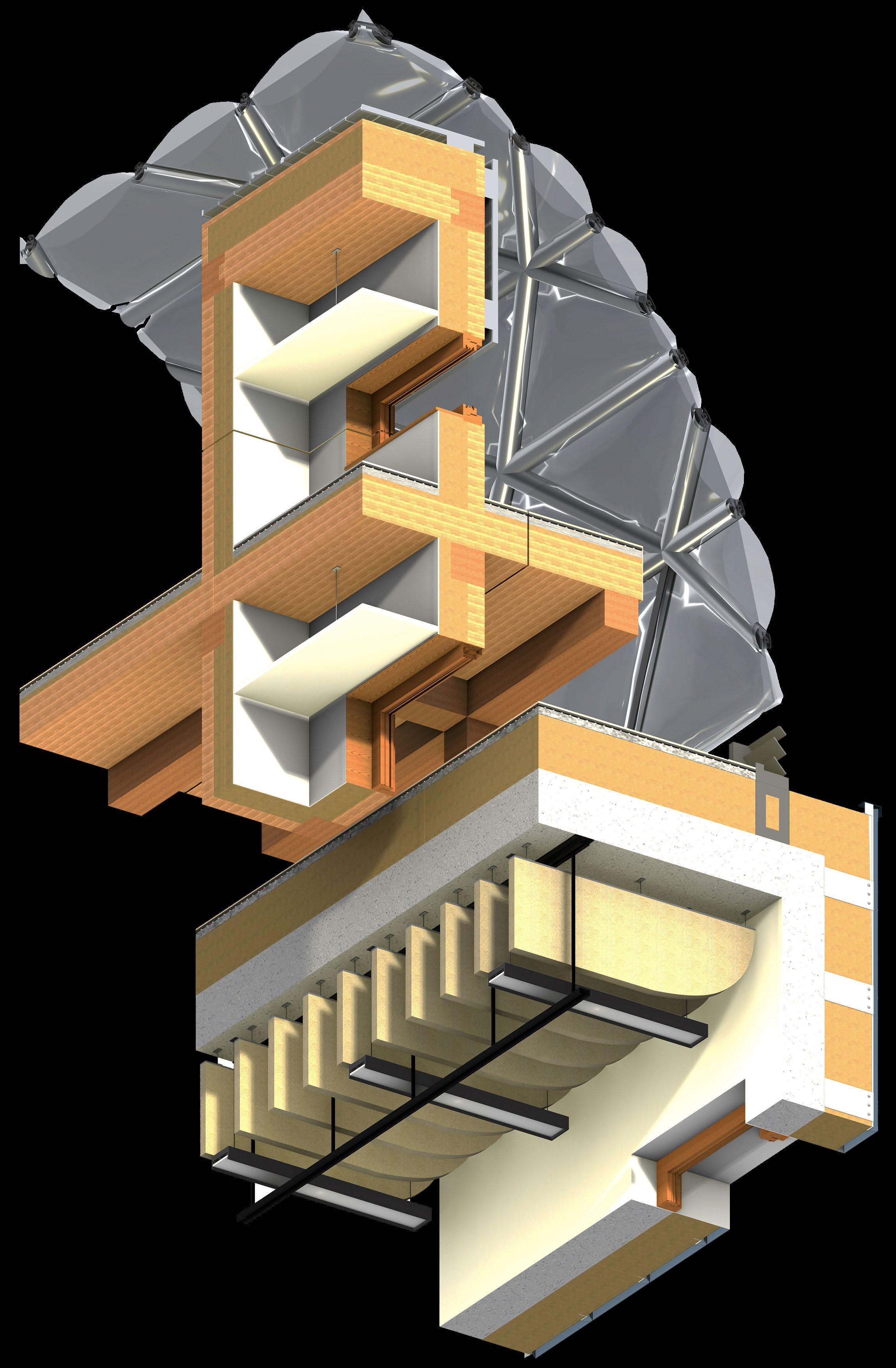
Solar panels
The solar panels take advantage of the abundant natural light in the building by generating electrical power, which is then used by operational appliances.
Three layer inflated ETFE membrane cushion
The ETFE cushions provide moderate insulation, weather proof the internal mass timber structure and the translucent nature of the membrane provides more controlled natural
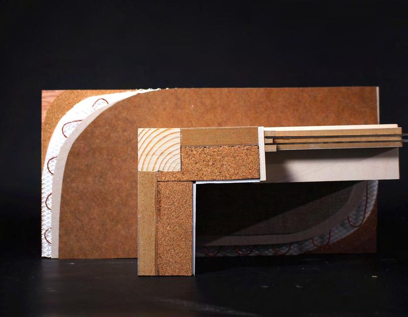
170 mm wood fibre insulation
100 mm CLT wall
The timber wall provides vertical support for the insulation and is responsible for the bracing against the lateral load. As the timber wall has a beautifully natural finish to it, it doesn’t need extra lining.
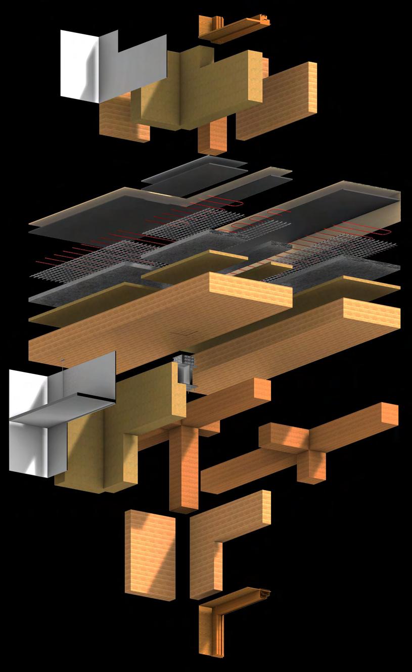
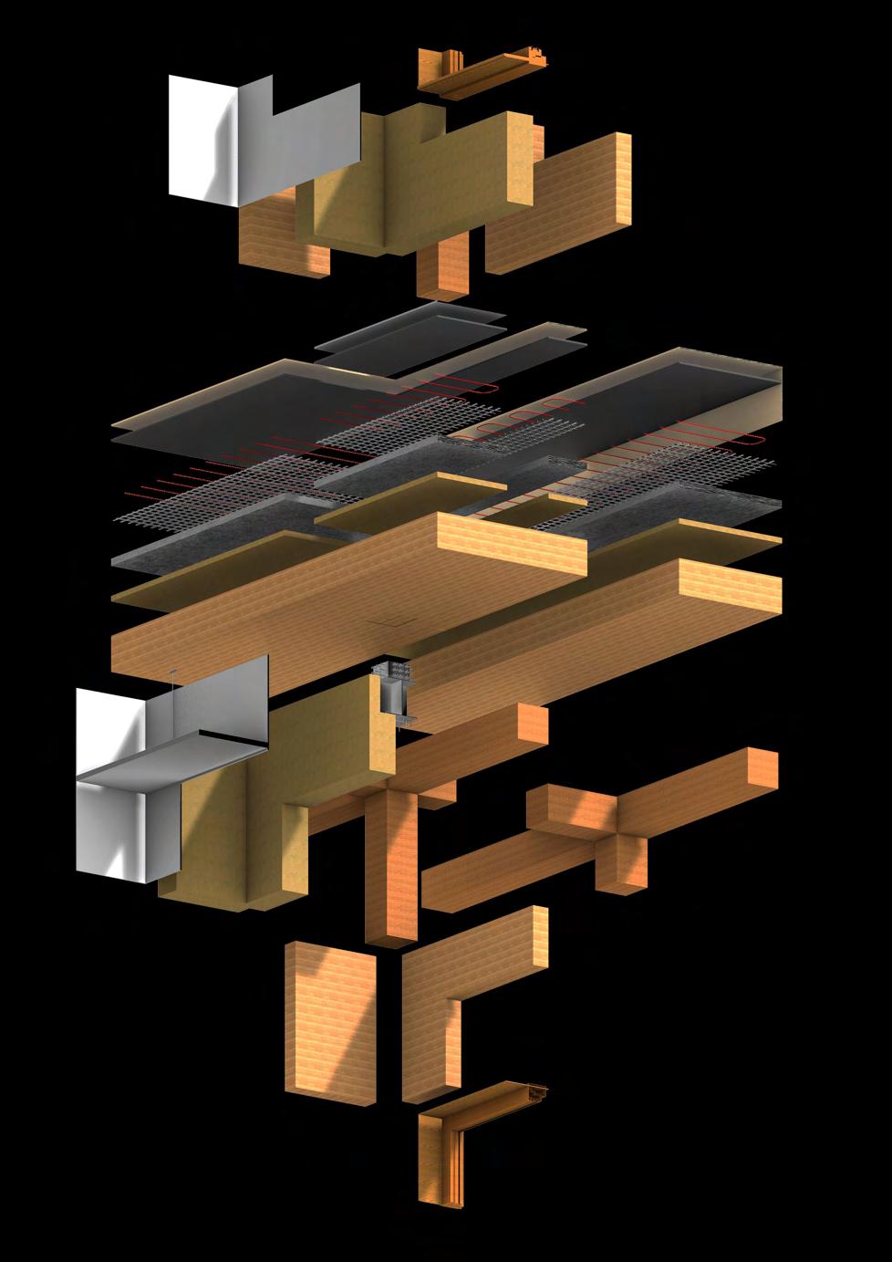
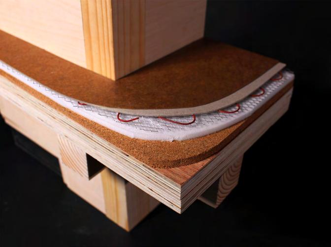
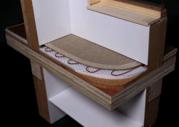
10 mm carpet floor finish
The medical rooms have a soft carpet floor finish for the patient’s comfort.
10 mm wood parquet floor finish
12 mm self leveling floor compound
Provides a level and even finish for the floor tiles or carpet.
Underfloor heating wire
As the floor-to-ceiling height of the building is quite high, the underfloor heating works in harmony with the HVAC system to provide a comfortable internal temperature.
Underfloor heating mat
40 mm acoustic fleece flooring Absorbs the sound impact from steps.
30 mm floor insulation Protects the CLT slabs from heat
300 mm wood fibre insulation
The thick insulation ensures the concrete part is well insulated and reaches Passivhaus standards.
Air barrier Provides air leakage control to prevent energy loss, drafts, and reduced thermal comfort.
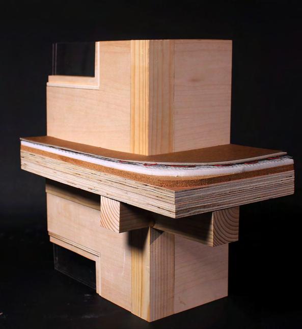
Connection detail
Primary structure
1:5 worm’s eye isometric drawing on A0
170 mm wood fibre insulation
Precedent study
1:5 tactile model
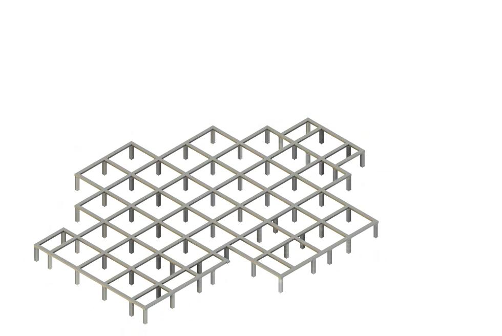
Prior to the on-site construction, the current building on the site needs to be demolished. I plan to recycle the former building’s concrete in the new building’s foundation to reduce construction waste and greenhouse gas emissions. The process involves collecting the debris from the demolition site, sorting them based on size and quality, and transporting it to the manufacturer. Then the concrete is crushed using various crushers, screened and reused for future use.