11 minute read

Best Practices & Design Improvement Items (Part II

Next Article
Safety First

Safety First

Technical Best Practices & Design Improvement Items – Part II

Following “Best Practices & Design Improvement Items – Part I”, published in the previous issue of Wavelength, the following additional measures have been adopted on board Company vessels with the aim of enhancing Ship and Crew safety and security:

Advertisement

• Fire Prevention • Protection against flooding • Safety for Crew • Security

Fire Prevention

Fires and explosions are the third largest cause of accidents, after collision and grounding. Fires on board ships are a complex problem and there are many potential consequences of a fire breaking out, including extensive damage, a collapse of infrastructure, explosions, loss of life, or even a total loss. In most cases, a fire starts as a small smouldering fire and then, after an incipient phase, it starts to spread very quickly. The spread of a fire is heavily dependent on ventilation and available fuel. Many studies and fire investigations have concluded that a quick response to a fire is the most important safety precaution. Hence, the implementation of fire safety systems based on Maritime Rules and Industry Standards on board Company vessels is crucial for preventing and overcoming the fire hazard. a. Fire detectors in public spaces and cabins Industry Standards require vessels to have an automatic system of fire detection in the accommodation, wheelhouse, Cargo Control Room (CCR), laundry, drying room, fire control station, pantry and galley areas. Furthermore, a fire detection system covering all cabins in addition to public rooms is strongly preferred. Figure 1: Fire detector in cabin To further enhance fire safety, some vessels of the fleet are also equipped with fire detectors installed inside the accommodation cabins and the same will be applied in the Company’s newbuilding projects. 
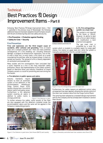
b. CO2 Fire extinguishing system i.w.o mast riser This system is not required by the Rules or SOLAS. However, its ability to deal with a fire on deck renders this modification a best practice to be applied. By Natassa Sakellariou and Christina Toki The gas mast riser is protected by a local CO2 system which is located in a suitable space (i.e cargo gear station, fire station on upper deck etc), while the system is manually operated from the CO2 cylinder location.

Figure 3: CO2 Fire extinguishing system for mast riser Furthermore, for safety reasons an additional control valve arrangement has been applied, allowing the remote control of the mast riser isolation valve from the Cargo Control Room. The same has been adopted as a standard design improvement item by the Company and has already been installed in several fleet vessels.

c. Fire Prevention in Engine Room Oil leakage hitting hot spots on engines is the most common cause of engine room fires on board ships. According to DNV casualty statistics, more than 60% of all engine room fires have been initiated by a hot spot. In order to eliminate the risk of fire in machinery spaces originating from flammable oil leaks coming into contact with hot surfaces, machinery parts are properly insulated. • Insulation and anti-splashing tapes

Insulation of engine room high surface temperature parts is a critical factor in avoiding the danger of fire ignition.

Hot surfaces in the Engine Room include all surfaces that can develop a temperature over 220oC.

Suitable insulation materials are provided for covering hot surfaces on board and must be replaced when deteriorated or soaked by oil.

Installation of anti-splashing tapes in flammable oil pressure pipes (in high and low-pressure oil systems) is also very important as it ensures that no oil spray or dripping from possible leaks hits any potentially hot surfaces, either by direct spray or by deflection.

A sufficient quantity of insulation material and antisplashing tapes must be always available on board for the immediate replacement of materials and tapes when deemed necessary.

Figure 5: Insulation and anti-splashing tapes in various locations

• Regular maintenance and testing of firefighting equipment (CO2 or High Expansion Foam System, Emergency fire pump, Fire & G.S. pumps, E/R local firefighting system, portable firefighting equipment) shall be carried out.

Figure 6: CO2 system for E/R and P/R Figure 7: High expansion foam system for E/R and P/R. • E/R Local Fire Fighting System: a suction line is provided from both F.W. Tanks for redundancy purposes.

Figure 8: E/R Local Fire Fighting system unit and sensors

• There shall be regular testing of the remote operation of quick closing valves and fire dampers.

Figure 9: Quick closing valves remote control station and valves

• M/E F.O. supply & circulating pumps and F.O. transfer pumps with magnetic couplings

Figure 10: Concept of the magnetic coupling

Approximately 20 years ago, magnetic couplings were introduced as a reliable solution for the elimination of oil leakages of fuel-related pumps inside the Engine Room. For pumps equipped with magnetic couplings, power is transmitted from the motor to the pump’s rotor set via permanent magnets. Instead of the traditional seal and coupling, the rotor shaft is equipped with permanent magnets. The rotor shaft is then sealed inside a non-magnetic can, through which no oil can leak. On the outer atmospheric side of the can, an outer rotor with permanent magnets is coupled to the driver. Based on this arrangement, there are no sliding contact seals and hence, no way for oil to escape, contributing significantly to fire or ignition control in the Engine Room.

Several fleet vessels are fitted with magnetic coupling pumps while in new building projects, this is a standard specification for M/E Fuel Oil supply and circulating pumps, and F.O transfer pumps.

Figure 11: M/E Fuel Supply pump & Circulating pump

Protection against flooding

Flooding accidents in the vessel’s machinery spaces attributed to pipe leakages, defective equipment or human error are still very common and their timely identification is crucial in order to protect the vessel’s integrity and stability.

a. Bilge high level alarms • Bilge levels must be continuously monitored and verified not only in the Engine Room but also in various other locations as per

Industry Standards. The additional spaces monitored for high bilge levels include the Pump Room,

Steering Gear Room, Emergency

Fire Pump Room and Bosun Store.

Figure 12: Bilge Alarm in Steering Gear Room • Proper operation of the Bilge level switches must be guaranteed and ensured through regular testing on a weekly basis. b. Proper maintenance & inspection of relevant equipment All equipment related to sea water suction and discharge (piping, valves, pumps, sea chests etc.) must be properly monitored, maintained and replaced when necessary, especially during the vessel’s drydocking/repair period. For this reason, the following practices have been adopted and are strongly recommended: • New overboard valves or replacement overboard valves must always be of the correct specification and material.

The material shall be cast steel and the pressure rating shall be as per specification. The valves must also be accompanied by a Class certificate in line with the vessel’s

Classification Society. • Polyethylene lined sea water pipes must be inspected during the vessel’s drydocking period to ensure that the lining condition is intact, as even a small defect can lead to lining deterioration and accelerated corrosion of the pipe. • An ultrasonic thickness measurement is recommended during the drydocking/repair period, especially on the overboard and suction pipes, as well as on the sea chest’s boundary areas. • The E/R emergency bilge suction valve and all other bilge suction valves shall be thoroughly inspected and maintenance must be scheduled to ensure their proper operation.

Figure 13: Emergency Bilge Suction valve

• Bilge, Fire and General service pumps must be overhauled at frequent intervals, including parts replacement and balancing during the vessel’s repair periods. • Spare overboard storm valves shall be also kept onboard for immediate action, if required.

c. Remote operation of the Pump Room direct bilge suction valve In order to minimize the impact of human error during the vessel’s operation, the remote operation of the Pump Room direct bilge suction valve has been integrated on several vessels of the fleet. The remote operation safeguards the integrity of the Pump Room against flooding in case the bilge suction valves have been left closed by mistake. In this case, the valves will be operated from the remote position, which in most cases is on the Pump Room entrance on the Upper Deck.

Figure 14: Remote operation of the Pump Room direct bilge suction valve in case of emergency (from Upper Deck).

Safety for Crew

In all vessels it is possible for the crew to be exposed to toxic vapours and gases such as hydrocarbons and H2S, which can cause various health problems and even death if concentrations are high. The only reliable method of determining vapour concentration is by testing with proper instruments. In this aspect, apart from a P/R Gas Detection System, the Company has applied some onboard design improvements, including a gas detection system in the Accommodation A/C inlets and in the Accommodation entrance.

Figure 15: Hydrocarbon, H2S & O2 sensors in pump room

Figure 16: Gas detection system in Accommodation A/C inlet and Accommodation entrance

In addition, a retrofit installation of leak free type P/V valves, which has already been performed in HSHI Suezmax tankers, ensures satisfactory leak tightness of pressure relief valves and maintenance of leakage-free operation. Following confirmation of their reliable operation, the leak free type P/V valves will also be retrofitted on additional tankers of the fleet during their upcoming drydocking/repair period.

Figure 17: Leak free P/V valves

Security

Maritime Security threats often appear and can lead to very high risks which can affect the crew and operation of the ship. Ship Security management and the implementation of procedures / measures are crucial to mitigate against maritime security threats and avoid security breaches. The Company has adopted some best practices such as the installation of a VSS (Vessel Security System), the fitting of additional steel doors and a Citadel in newbuildings in order to strengthen and improve the integrity of vessel security. a. VSS

Figure 18: VSS Main Alarm Panel and sensor

The Vessel Security System is an innovative security system which helps to avoid any unknown security breach. It consists of the main alarm panel and the inductive proximity switches (sensors), which provide the necessary information for the main control unit concerning the position of the doors. b. Steel doors Secondary doors are fitted to outside or inside access points to the accommodation block and the engine room. These obstruct intruders with a barrier that cannot easily be penetrated. Doors present a smooth surface without handles or locks and the crew is able to secure them from the inside, thereby gaining time to retreat to a safe muster point and secure the doors.

Figure 19: Steel doors

c. Citadel With the increasing incidence of piracy attacks, there has been a corresponding increase in defensive measures applied by vessels. One of the measures is the retreat to a ‘Citadel’. A Citadel is designed and constructed in order to provide effective protection against determined intrusion. In the Company’s Newbuilding tankers, the steering gear room will be used as a citadel with the following provisions: • 1 Steel door from the steering gear room to the engine room • 1 Steel door in the steering gear room entrance from the upper deck • 1 Hinged Hatch on the upper deck with an anti-pirate lock device • 1 Manual Damper below the ventilators handled by chain • 2 redundancy natural ventilations outside the E/C wall Apart from basic survival items, a portable toilet and proper ventilation, a Citadel must have an independent means of communication with the vessel operator's Security Officer. In this aspect, Newbuilding vessels will be fitted with the following communications systems: • 1 set of Iridium telephones with a concealed antenna in the

W/H top • 1 UPS for the Iridium telephone • 1 VHF Radio Telephone, a transceiver control unit and a handset • 1 remote Inmarsat FB500 telephone It should also be noted that existing vessels are equipped with a voice telephone connected with Inmarsat in the steering gear room as a means of communication with the vessel operator's Security Officer.

This article is from: