
11 minute read
Main Engine Failures and Blackouts
Technical Main Engine Failures and Blackouts
a. Introduction
Advertisement
In the recent past the shipping industry has noted an increasing number of blackouts and main engine failures, which can result in a total loss of propulsion and steering capability. The risks to the vessel and crew become critical and may result in a major casualty when they occur while maneuvering in restricted areas (traffic lanes, channels), entering or leaving port or navigating close to a coast during heavy weather.
b. Consequences of Propulsion Loss
The most serious consequences of a blackout or propulsion loss are contact, collision and/or grounding.
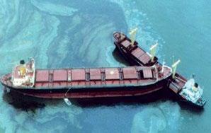
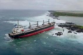
Fig. 1: Collision Fig. 2: Grounding
Furthermore, a significant number of claims for third party property damage, many of which were enormously expensive, could be attributed directly or indirectly to main engine failures or electrical blackouts.
c. Possible Causes of Propulsion Loss
According to a detailed analysis of claims related to propulsion loss by UK P&I Club for a period of five (5) years, the main causes of propulsion loss are as follows:
Insufficient or ineffective maintenance
Equipment failure
Human error
Fire

Other
It is worth mentioning that blackouts and main engine failures tend to occur when the vessel begins maneuvering in confined waters or enters and leaves port. Under these operating conditions, the stable electric load during the sea passage is replaced by variable electric power requirements i.e. additional electric load of steering motors, deck machinery etc. c1. Possible Causes of Main Engine Failure The main possible causes of main engine failure are as follows: • Starting failures • Fuel supply issues • Improper fuel changeover procedure when entering or exiting ECA areas • Mechanical failure • Control equipment failure • Blackout • Human error • Other causes
By Yiannis Pantos, Director/Technical
c1.1. Starting Failures
Difficulty Possible Cause Remedy
The pressure in the starting air receiver is too low. Start the main air compressors. Check that they are working properly.
The valves on the starting air receiver or the starting air distributor are closed. Open the valves.
There is no pressure in the control air system. Check the pressure (normally 7 bar). If it is too low, change over to the other reducing valve and clean the filter.
The main engine fails to turn on the starting air after the START order has been given.
The main starting valve is locked in the closed condition.
The main starting valve does not function due to the activated turning gear locking device.
The pistons in the starting air distributor are sticking.
The starting air distributor is wrongly adjusted.
The control valve for the starting air distributor is sticking. Lift the locking plate to the working position.
Release the turning gear locking device.
The starting air distributor is to be overhauled.
Check the timing marks. Re-adjust the starting air distributor.
Overhaul the control valve slide.
The starting air valves in the cylinder covers are defective. Pressure – test the valves. Replace or overhaul the defective valves.
It should be noted that an excessive number of main engine starts / stops while maneuvering will deplete the pressure in the main air bottles. This may lead to main engine starting failure. It is, therefore, very important to monitor the main starting air pressure while maneuvering and for the pilot and bridge team to be aware of the maximum number of consecutive engine starts they can demand.
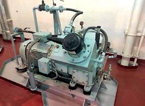

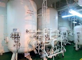
Fig. 3: Main air compressor Fig. 4: Main air receivers
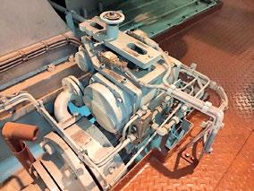
Fig. 5: M/E - Main air starting valve Fig. 6: M/E – Main air distributor
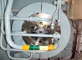
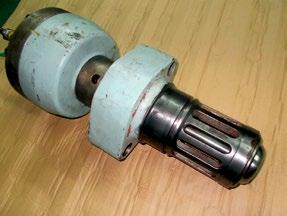

Fig. 7: M/E – Starting air valve
c1.2. Fuel Supply Issues
Difficulty Possible Cause Remedy
The fuel filter is blocked. Clean the filter.
The main engine turns on the fuel, but runs unevenly and will not pick up rpm.
The fuel pressure is too low.
One or more cylinders are not firing.
There is water in the fuel. Increase the pressure.
Check the suction valve and puncture valve in the fuel pump. Check the individual index. If there is no index, check the rod connections and the safety shutdown system. If no fault is found, change the fuel valves.
Drain the settling and service tanks. Improve the efficiency of the fuel oil separators.
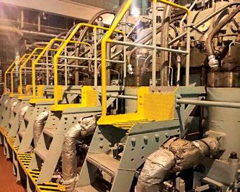
Fig. 8: M/E Fuel pumps & puncture valves assemblies c1.3. Control Equipment Failure
Difficulty Possible Cause Remedy
The puncture valves of the fuel pumps are not deaerated. Find the cause of the stop – order and correct the fault.
The main engine turns on the starting air but stops after receiving the order to run on fuel.
The main engine does not reverse when order is given.
There has been an engine shutdown.
There is a faulty adjustment of the maneuvering gear. Check the pressures and temperatures. Check whether the trips for high cooling temperature or low lub oil pressure are functioning properly.
Check the rod connections. Check that the fuel pump index corresponds to the shop test results.
There is a fault in the governor. Locate and rectify the fault.
The solenoid valve coil does not receive voltage for the desired direction of rotation.
The control air signal for the desired direction of rotation does not reach the engine. Locate and rectify the fault.
Find the defective valve or pipe which stops the signal. Repair or replace the valve or pipe.

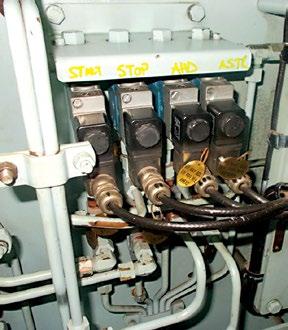
Fig.9: M/E fuel p/p puncture v/v Fig. 10: Solenoid v/v for ahead/ astern
Fig. 11: M/E pneumatic control system Fig. 12: M/E governor

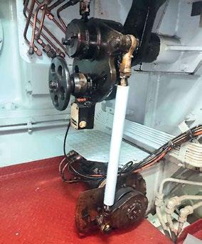
c1.4. Mechanical failure The following mechanical problems can lead to main engine failure: • Lack of compression • Scavenge fire • Crankcase oil mist • Loss of lubrication • Intermediate shaft bearing failure • Stern tube bearing failure


Fig. 13: M/E Oil mist detector Fig. 14: Intermediate shaft bearing
c1.5. Propulsion loss when entering or exiting ECA There have been several reported propulsion loss incidents which have been associated with improper fuel changeover procedures when entering or exiting an Emission Control Area. (ECA). Furthermore, the use of ultra low sulphur distillate fuels may cause fuel leakages from fuel pumps, fuel pump and fuel valve wear, and the sticking of fuel pumps barrels/plungers.
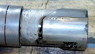
Fig. 15: Damaged fuel pump plunger Fig. 16: Fuel pump leakage
c1.6. Blackout – Loss of electrical power A significant percentage of engine maneuvering failures is attributed to a loss of electrical power i.e. blackout.
c2. Blackouts
c2.1. Definitions Blackout: A “blackout situation” means that the main and auxiliary machinery installations, including the main power supply, are out of operation but the services for bringing them into operation (e.g. compressed air, starting current from batteries etc.) are available. Dead Ship Condition: Dead Ship Condition is the condition under which the main propulsion plant, boilers and auxiliary machinery are not in operation due to the absence of power. In addition, no stored energy for starting and operating the propulsion plant, the main source of electrical power and other essential auxiliaries is available.
c2.2. Possible Causes of Blackouts According to UK P&I Club data, the main causes of blackouts are as follows: A detailed list of the possible causes of blackouts can be found below: a. Human error The highest number of blackouts was attributable to human error e.g. stopping or tripping an on-load generator, pressing the wrong button etc. b. Control equipment failure • Governor failure • Defective trips for high cooling temperature or low lub oil pressure c. Automation failure • Automatic Voltage Regulator (AVR) defect • Load control / sharing failure • Loss of exciter voltage due to diode failure d. Electrical failure • Overload • Reverse power trip failure • Preferential trip failure A significant number of blackouts is caused by electrical failures when starting large electric motors (e.g. for mooring winches, cranes etc.) and the available electrical power is not sufficient. Starting large motors may trip breakers and lead to blackouts. e. Fuel issues • Blocked filters • Improper changeover procedures • Poor fuel quality i.e. water in fuel • Fuel supply piping and pump failure f. Mechanical failure • Lack of compression • Engine seizure • Loss of lubrication • Overheating g. Other causes - Fire in electrical panel/main switchboard

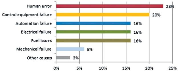
Fig. 17: Diesel generators & alternators Fig. 18: Main switchboard Fig. 19: Automatic voltage regulator (AVR)
- Emergency Generator In the case of a blackout, it is of paramount importance to ensure the proper operation of the emergency generator. The emergency generator shall be started automatically upon failure of the electrical supply from the main source of electrical power and shall be automatically connected to the emergency switchboard. The automatic starting system and the characteristic of the prime mover shall permit the emergency generator to carry its full rated load quickly as long as it is safe and practicable, up to a maximum of 45 seconds. As per the SOLAS regulations, the capacity of the emergency generator shall be sufficient to restore propulsion to the ship in conjunction with other machinery as appropriate, from a dead ship condition within 30 minutes after blackout. All engineers should be fully aware of the following possible causes of emergency generator failures: • Batteries in poor condition • Switchboard selector switch not in “auto” start position • Failure of starting system • Poor quality or contaminated fuel oil • Fuel oil starvation

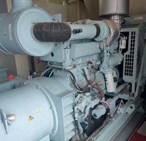
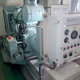
Fig. 20: Emergency generator
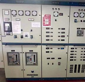
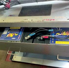
Fig. 21 Emergency switchboard Fig. 22 Emergency generator starting batteries
- Operational guidance for preventing main engine failures and blackouts There are a number of recommendations for preventing main engine failures and blackouts, thereby reducing the risk of propulsion loss.

Preventive Actions 1. The maintenance of all equipment should be carried out as per the Company’s “Planned Maintenance System” (PMS). 2. Main engine and diesel generator safety devices (alarms & trips) should be operational and regularly tested as per the PMS. 3. The main engine pneumatic control system is to be kept well maintained as per the Maker’s recommendations and the PMS. The control air to be kept clean and dry.
Therefore, it is of paramount importance that the air dryer is in good working condition and properly maintained. 4. The changeover procedures from one grade of fuel to another should be in accordance with the Maker’s recommendations. All engineers should be fully familiar with all engine room systems and their pipelines, including the changeover procedures. 5. During maneuvering operations, the starting air pressure is to be carefully monitored. 6. During maneuvering operations or when on standby, run two (2) generators in parallel whilst ensuring there is sufficient electrical power availability should one generator either stop or trip. Monitor and balance the switchboard power loads equally. 7. Test the astern operation of the main engine prior to arriving at the pilot station and, if practicable, before approaching the berth. 8. All engineers should be fully familiar with the operation & control of the main engine from the engine control room and locally from the emergency control stand. 9. Ensure that no maintenance is carried out on filters or fuel systems when on standby or approaching restricted navigational areas. 10. Ensure water is regularly drained from the fuel oil tanks in order to avoid water build-up and carryover in the fuel. 11. Test & Operation of the Emergency Generator • Ensure that weekly tests of the emergency generator are carried out with the battery charger disconnected from the mains. • Ensure that the batteries are checked as part of the weekly routine. • Ensure that all means of starting the emergency generator are tested and that all crew members are familiar with them. • Ensure that the emergency generator is operated on load as close to the maximum capacity as possible, for at least one hour, every three (3) months. 12. Over-current tests for main generator breakers have to be carried out to the satisfaction of the Class Surveyors during periodic surveys. 13. A regular thermographic survey of the switchboard should be carried out to check for loose connections or overheating equipment. 14. Establish procedures to ensure that there is adequate electrical power available before starting up mooring equipment or other heavy equipment, bearing in mind that the simultaneous starting of large electric motors will lead to a large power surge and possible overload. 15. All crew members are to be familiar with the recovery procedure after a blackout or “dead ship condition”. 16. Ensure that any blackout and/or propulsion incident is investigated and a root cause is determined. 17. Ensure that the corrective actions of a possible previous blackout/loss of propulsion have been duly implemented in order to prevent a reoccurance.

